LD-W-1 - Tams
LD-W-1 - Tams
LD-W-1 - Tams

You also want an ePaper? Increase the reach of your titles
YUMPU automatically turns print PDFs into web optimized ePapers that Google loves.
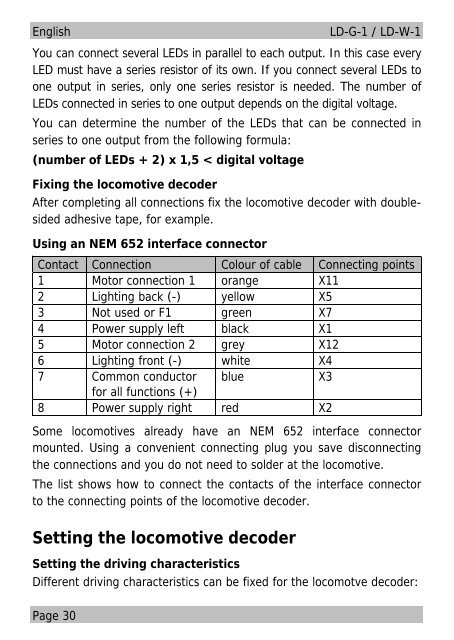
EnglishPage 30<strong>LD</strong>-G-1 / <strong>LD</strong>-W-1You can connect several LEDs in parallel to each output. In this case everyLED must have a series resistor of its own. If you connect several LEDs toone output in series, only one series resistor is needed. The number ofLEDs connected in series to one output depends on the digital voltage.You can determine the number of the LEDs that can be connected inseries to one output from the following formula:(number of LEDs + 2) x 1,5 < digital voltageFixing the locomotive decoderAfter completing all connections fix the locomotive decoder with doublesidedadhesive tape, for example.Using an NEM 652 interface connectorContact Connection Colour of cable Connecting points1 Motor connection 1 orange X112 Lighting back (-) yellow X53 Not used or F1 green X74 Power supply left black X15 Motor connection 2 grey X126 Lighting front (-) white X47 Common conductor blue X3for all functions (+)8 Power supply right red X2Some locomotives already have an NEM 652 interface connectormounted. Using a convenient connecting plug you save disconnectingthe connections and you do not need to solder at the locomotive.The list shows how to connect the contacts of the interface connectorto the connecting points of the locomotive decoder.Setting the locomotive decoderSetting the driving characteristicsDifferent driving characteristics can be fixed for the locomotve decoder: