SCTF loop for noise reduction in Autozero amplifiers
SCTF loop for noise reduction in Autozero amplifiers
SCTF loop for noise reduction in Autozero amplifiers

Create successful ePaper yourself
Turn your PDF publications into a flip-book with our unique Google optimized e-Paper software.
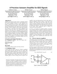
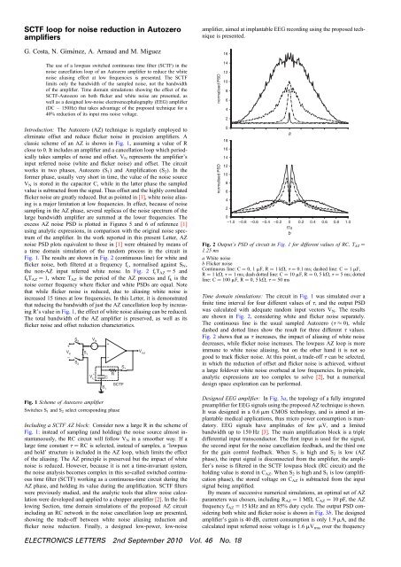
<strong>SCTF</strong> <strong>loop</strong> <strong>for</strong> <strong>noise</strong> <strong>reduction</strong> <strong>in</strong> <strong>Autozero</strong><strong>amplifiers</strong>G. Costa, N. Giménez, A. Arnaud and M. MiguezThe use of a lowpass switched cont<strong>in</strong>uous time filter (<strong>SCTF</strong>) <strong>in</strong> the<strong>noise</strong> cancellation <strong>loop</strong> of an <strong>Autozero</strong> amplifier to reduce the white<strong>noise</strong> alias<strong>in</strong>g effect at low frequencies is presented. The <strong>SCTF</strong>limits only the bandwidth of the sampled <strong>noise</strong>, not the bandwidthof the amplifier. Time doma<strong>in</strong> simulations show<strong>in</strong>g the effect of the<strong>SCTF</strong>-<strong>Autozero</strong> on both flicker and white <strong>noise</strong> are presented, aswell as a designed low-<strong>noise</strong> electroencephalography (EEG) amplifier(DC – 150Hz) that takes advantage of the proposed technique <strong>for</strong> a40% <strong>reduction</strong> of its <strong>in</strong>put rms <strong>noise</strong> voltage.Introduction: The <strong>Autozero</strong> (AZ) technique is regularly employed toelim<strong>in</strong>ate offset and reduce flicker <strong>noise</strong> <strong>in</strong> precision <strong>amplifiers</strong>. Aclassic scheme of an AZ is shown <strong>in</strong> Fig. 1, assum<strong>in</strong>g a value of Rclose to 0. It <strong>in</strong>cludes an amplifier and a cancellation <strong>loop</strong> which periodicallytakes samples of <strong>noise</strong> and offset. V N represents the amplifier’s<strong>in</strong>put referred <strong>noise</strong> (white and flicker <strong>noise</strong>) and offset. The circuitworks <strong>in</strong> two phases, <strong>Autozero</strong> (S 1 ) and Amplification (S 2 ). In the<strong>for</strong>mer phase, usually very short <strong>in</strong> time, the value of the <strong>noise</strong> sourceV N is stored <strong>in</strong> the capacitor C, while <strong>in</strong> the latter phase the sampledvalue is subtracted from the signal. Thus offset and the highly correlatedflicker <strong>noise</strong> are greatly reduced. But as po<strong>in</strong>ted <strong>in</strong> [1], white <strong>noise</strong> alias<strong>in</strong>gis a major limitation at low frequencies. In effect, because of <strong>noise</strong>sampl<strong>in</strong>g <strong>in</strong> the AZ phase, several replicas of the <strong>noise</strong> spectrum of thelarge bandwidth amplifier are summed at the lower frequencies. Theexcess AZ <strong>noise</strong> PSD is plotted <strong>in</strong> Figures 5 and 6 of reference [1]us<strong>in</strong>g analytic expressions, <strong>in</strong> comparison with the orig<strong>in</strong>al <strong>noise</strong> spectrumof the amplifier. In the work reported <strong>in</strong> this present Letter, AZ<strong>noise</strong> PSD plots equivalent to those <strong>in</strong> [1] were obta<strong>in</strong>ed by means ofa time doma<strong>in</strong> simulation of the random process <strong>in</strong> the circuit <strong>in</strong>Fig. 1. The results are shown <strong>in</strong> Fig. 2 (cont<strong>in</strong>uous l<strong>in</strong>e) <strong>for</strong> white andflicker <strong>noise</strong>, both filtered at a frequency f c , normalised aga<strong>in</strong>st S N ,the non-AZ <strong>in</strong>put referred white <strong>noise</strong>. In Fig. 2 f c T AZ ¼ 5 andf k T AZ ¼ 1, where T AZ is the period of the AZ process and f k is the<strong>noise</strong> corner frequency where flicker and white PSDs are equal. Notethat while flicker <strong>noise</strong> is reduced, due to alias<strong>in</strong>g white <strong>noise</strong> is<strong>in</strong>creased 15 times at low frequencies. In this Letter, it is demonstratedthat reduc<strong>in</strong>g the bandwidth of just the AZ cancellation <strong>loop</strong> by <strong>in</strong>creas<strong>in</strong>gR’s value <strong>in</strong> Fig. 1, the effect of white <strong>noise</strong> alias<strong>in</strong>g can be reduced.The total bandwidth of the AZ amplifier is preserved, as well as itsflicker <strong>noise</strong> and offset <strong>reduction</strong> characteristics.S 2 V N+++ –V <strong>in</strong> S 1– –S 2S 1+V c C R –<strong>SCTF</strong>S 1Fig. 1 Scheme of <strong>Autozero</strong> amplifierSwitches S 1 and S 2 select correspond<strong>in</strong>g phaseInclud<strong>in</strong>g a <strong>SCTF</strong> AZ block: Consider now a large R <strong>in</strong> the scheme ofFig. 1: <strong>in</strong>stead of sampl<strong>in</strong>g (and hold<strong>in</strong>g) the <strong>noise</strong> source almost <strong>in</strong>stantaneously,the RC circuit will follow V N <strong>in</strong> a smoother way. If alarge time constant t ¼ RC is selected, <strong>in</strong>stead of samples, a ‘lowpassand hold’ structure is <strong>in</strong>cluded <strong>in</strong> the AZ <strong>loop</strong>, which limits the effectof the alias<strong>in</strong>g. The AZ pr<strong>in</strong>ciple is preserved but the impact of white<strong>noise</strong> is reduced. However, because it is not a time-<strong>in</strong>variant system,the <strong>noise</strong> analysis becomes complex <strong>in</strong> this so-called switched cont<strong>in</strong>uoustime filter (<strong>SCTF</strong>) work<strong>in</strong>g as a cont<strong>in</strong>uous-time circuit dur<strong>in</strong>g theAZ phase, and hold<strong>in</strong>g its value dur<strong>in</strong>g the amplification. <strong>SCTF</strong> filterswere previously studied, and the analytic tools that allow <strong>noise</strong> calculationwere developed and applied to a chopper amplifier [2]. In the follow<strong>in</strong>gSection, time doma<strong>in</strong> simulations of the proposed AZ circuit<strong>in</strong>clud<strong>in</strong>g an RC network <strong>in</strong> the <strong>noise</strong> cancellation <strong>loop</strong> are presented,show<strong>in</strong>g the trade-off between white <strong>noise</strong> alias<strong>in</strong>g <strong>reduction</strong> andflicker <strong>noise</strong> <strong>reduction</strong>. F<strong>in</strong>ally, a designed low-power, low-<strong>noise</strong>V outamplifier, aimed at implantable EEG record<strong>in</strong>g us<strong>in</strong>g the proposed techniqueis presented.normalised PSDnormalised PSD1614121086420181614121086420–1.0 –0.8 –0.6 –0.4 –0.2 0fTsba0.2 0.4 0.6 0.8 1.0Fig. 2 Output’s PSD of circuit <strong>in</strong> Fig. 1 <strong>for</strong> different values of RC, T AZ ¼1.25 msa White <strong>noise</strong>b Flicker <strong>noise</strong>Cont<strong>in</strong>uous l<strong>in</strong>e: C ¼ 0, 1 mF, R ¼ 1kV, t ¼ 0.1 ms; dashed l<strong>in</strong>e: C ¼ 1 mF,R ¼ 1kV, t ¼ 1 ms; dash dotted l<strong>in</strong>e: C ¼ 10 mF, R ¼ 0, 5 kV, t ¼ 5 ms; dottedl<strong>in</strong>e: C ¼ 100 mF, R ¼ 0, 5 kV, t ¼ 50 msTime doma<strong>in</strong> simulations: The circuit <strong>in</strong> Fig. 1 was simulated over af<strong>in</strong>ite time <strong>in</strong>terval <strong>for</strong> four different values of t, and the output PSDwas calculated with adequate random <strong>in</strong>put vectors V N . The resultsare shown <strong>in</strong> Fig. 2, consider<strong>in</strong>g white and flicker <strong>noise</strong> separately.The cont<strong>in</strong>uous l<strong>in</strong>e is the usual sampled <strong>Autozero</strong> (t ≈ 0), whiledashed and dotted l<strong>in</strong>es show the result <strong>for</strong> three different t values.Fig. 2 shows that as t <strong>in</strong>creases, the impact of alias<strong>in</strong>g of white <strong>noise</strong>decreases, while flicker <strong>noise</strong> <strong>in</strong>creases. The lowpass AZ <strong>loop</strong> is moreimmune to white <strong>noise</strong> alias<strong>in</strong>g, but on the other hand it is not sogood to track flicker <strong>noise</strong>. At this po<strong>in</strong>t, a trade-off t can be selected,<strong>in</strong> which the <strong>reduction</strong> of offset and flicker <strong>noise</strong> is achieved, withouta large foldover white <strong>noise</strong> overhead at low frequencies. In pr<strong>in</strong>ciple,analytic expressions are too complex to solve [2], but a numericaldesign space exploration can be per<strong>for</strong>med.Designed EEG amplifier: In Fig. 3a, the topology of a fully <strong>in</strong>tegratedpreamplifier <strong>for</strong> EEG signals us<strong>in</strong>g the proposed AZ technique is shown.It was designed <strong>in</strong> a 0.6 mm CMOS technology, and is aimed at implantablemedical applications, thus micro power consumption is mandatory.EEG signals have amplitudes of few mV, and a limitedbandwidth up to 150 Hz [3]. The ma<strong>in</strong> amplification block is a tripledifferential <strong>in</strong>put transconductor. The first <strong>in</strong>put is used <strong>for</strong> the signal,the second <strong>in</strong>put <strong>for</strong> the <strong>noise</strong> cancellation feedback, and the third one<strong>for</strong> the ga<strong>in</strong> control feedback. When S 1 is high and S 2 is low (AZphase), the <strong>in</strong>put signal is disconnected from the amplifier, the amplifier’s<strong>noise</strong> is filtered <strong>in</strong> the <strong>SCTF</strong> lowpass block (RC circuit) and thehold<strong>in</strong>g value is stored <strong>in</strong> C AZ . When S 2 is high and S 1 is low (amplificationphase), the stored voltage on C AZ is subtracted from the <strong>in</strong>putsignal be<strong>in</strong>g amplified.By means of successive numerical simulations, an optimal set of AZparameters was chosen, <strong>in</strong>clud<strong>in</strong>g R AZ ¼ 1MV, C AZ ¼ 10 pF, the AZfrequency f AZ ¼ 15 kHz and an 85% duty cycle. The output PSD consider<strong>in</strong>gboth white and flicker <strong>noise</strong> is shown <strong>in</strong> Fig. 3b. The designedamplifier’s ga<strong>in</strong> is 40 dB, current consumption is only 1.9 mA, and thecalculated <strong>in</strong>put referred <strong>noise</strong> voltage is 1.6 mV rms over the frequencyELECTRONICS LETTERS 2nd September 2010 Vol. 46 No. 18
ange 0.5–150 Hz. It should be noted that the <strong>in</strong>put rms <strong>noise</strong> is 40%lower <strong>in</strong> comparison to an estimated 2.3 mV rms value, if a traditionalsampl<strong>in</strong>g AZ (t ¼ 0) is applied to the same amplifier.S 2 V N– +S+V i 2 S 1– V 1+V– 2+V– 3S 2S 2V oC LConclusion: It has been demonstrated that by reduc<strong>in</strong>g the bandwidth ofthe <strong>noise</strong> cancellation <strong>loop</strong> <strong>in</strong> a switched way (<strong>SCTF</strong>), the effect of white<strong>noise</strong> alias<strong>in</strong>g can be attenuated <strong>in</strong> AZ <strong>amplifiers</strong>. Although the result<strong>in</strong>gflicker <strong>noise</strong> PSD <strong>in</strong>creases, the total <strong>in</strong>put rms <strong>noise</strong> can be reduced <strong>in</strong>comparison to a classical AZ amplifier if the adequate AZ parametersand circuit elements are selected. The result was applied to the designof a precision amplifier <strong>for</strong> EEG signals.Acknowledgment: The authors thank ANII (Agencia Nacional deInvestigación e Innovación, Uruguay) <strong>for</strong> f<strong>in</strong>ancial support throughproject FCE2007_592.S 1S 2S 1SVn, V 2 /Hz × 10 –14<strong>SCTF</strong>C AZR AZR+G m–V CMa3.02.52.01.51.00.50–1.0 –0.8 –0.6 –0.4 –0.2 0fTsb0.2 0.4 0.6 0.8 1.0Fig. 3 Designed amplifier <strong>for</strong> EEG signals, and output PSD consider<strong>in</strong>gboth white and flicker <strong>noise</strong>a Designed amplifier <strong>for</strong> EEG signalsb Output PSD consider<strong>in</strong>g both white and flicker <strong>noise</strong># The Institution of Eng<strong>in</strong>eer<strong>in</strong>g and Technology 201027 May 2010doi: 10.1049/el.2010.1456G. Costa, N. Giménez, A. Arnaud and M. Miguez (Department ofElectrical Eng<strong>in</strong>eer<strong>in</strong>g, Catholic University of Uruguay, MontevideoCP 11700, Uruguay)E-mail: gcosta@ieee.orgReferences1 Enz, C.C., and Temes, G.C.: ‘Circuit techniques <strong>for</strong> reduc<strong>in</strong>g the effectsof op-amp imperfections: autozero<strong>in</strong>g, correlated double sampl<strong>in</strong>g, andchopper stabilization’, Proc. IEEE, 1996, 84, (11), pp. 1584–16142 Arnaud, A., and Miguez, M.R.: ‘On the evaluation of the exact output ofa switched cont<strong>in</strong>uous-time filter and applications’, IEEE Trans. CircuitsSyst. I, Reg. Pprs, 2008, 55, (6), pp. 1421–14293 Denison, T., Consoer, K., Kelly, A., Hachenburg, A., and Santa, W.: ‘A2.2 mW 94nV/ p Hz, chopper-stabilized <strong>in</strong>strumentation amplifier <strong>for</strong>EEG detection <strong>in</strong> chronic implants’. IEEE Int. Solid-State CircuitsConf., (ISSCC 2007), Dig. Tech. Pprs, San Francisco, CA, USA,February 2007, pp. 162–594ELECTRONICS LETTERS 2nd September 2010 Vol. 46 No. 18