recent advances in haptic rendering and applications - Computer ...
recent advances in haptic rendering and applications - Computer ...
recent advances in haptic rendering and applications - Computer ...

You also want an ePaper? Increase the reach of your titles
YUMPU automatically turns print PDFs into web optimized ePapers that Google loves.
RECENT ADVANCES INHAPTIC RENDERING ANDAPPLICATIONSEdited by M<strong>in</strong>g C. L<strong>in</strong> <strong>and</strong> Miguel A. OtaduyCopyright © 20051
ORGANIZERSM<strong>in</strong>g C. L<strong>in</strong>Department of <strong>Computer</strong> ScienceUniversity of North Carol<strong>in</strong>aChapel Hill, NC 27599-3175l<strong>in</strong>@cs.unc.eduPHO: 919-962-1974FAX: 919-962-1799Miguel OtaduyDepartment of <strong>Computer</strong> ScienceInstitute of Scientific Comput<strong>in</strong>gETH ZentrumCH - 8092 Zürichotaduy@<strong>in</strong>f.ethz.ch3
LECTURERS• Ela<strong>in</strong>e Cohen, University of Utahcohen@cs.utah.edu• David Johnson, University of Utahdejohnso@cs.utah.edu• Roberta Klatzky, Carnegie Mellon Universityklatzky@cmu.edu• M<strong>in</strong>g L<strong>in</strong>, University of North Carol<strong>in</strong>a at Chapel Hilll<strong>in</strong>@cs.unc.edu• Bill McNeely, Boe<strong>in</strong>g Researchbill.mcneely@boe<strong>in</strong>g.com• Miguel Otaduy, ETH Zurichotaduy@<strong>in</strong>f.ethz.ch• D<strong>in</strong>esh Pai, Rutgers Universitydpai@cs.rutgers.edu• Ken Salisbury, Stanford University & Intuitive Surgery, Incjks@robotics.stanford.edu• Hong Tan, Purdue Universityhongtan@purdue.edu• Russell Taylor, University of North Carol<strong>in</strong>a at Chapel Hilltaylorr@cs.unc.edu4
BIOGRAPHICAL SKETCHES OF LECTURERSEla<strong>in</strong>e Cohen is a professor of computer science at the University of Utah. Sheis co-head of the Geometric Design <strong>and</strong> Computation Project <strong>and</strong> co-author ofGeometric Model<strong>in</strong>g with Spl<strong>in</strong>es: An Introduction (A. K. Peters, 2001). Dr.Cohen has focused her research <strong>in</strong> computer graphics, geometric model<strong>in</strong>g, <strong>and</strong>manufactur<strong>in</strong>g, with emphasis on complex sculptured models represented us<strong>in</strong>gNURBS (Non-Uniform Rational B-spl<strong>in</strong>es) <strong>and</strong> NURBS-features. Results <strong>in</strong>manufactur<strong>in</strong>g research have been focused on automat<strong>in</strong>g process plann<strong>in</strong>g,automatic toolpath generation for models hav<strong>in</strong>g many surfaces, optimiz<strong>in</strong>g bothwith<strong>in</strong> <strong>and</strong> across manufactur<strong>in</strong>g stages <strong>and</strong> fixture automation. She has alsobeen work<strong>in</strong>g on issues related to telepresence <strong>and</strong> design collaborations <strong>in</strong>virtual environments. Recent research has produced algorithms for determ<strong>in</strong><strong>in</strong>gboth visibility <strong>and</strong> accessibility of one object by another. Computation of such<strong>in</strong>formation is necessary for manufactur<strong>in</strong>g, assembly plann<strong>in</strong>g, graphics, <strong>and</strong>virtual environments. Research <strong>in</strong> <strong>haptic</strong>s has been focused on develop<strong>in</strong>g newapproaches to solv<strong>in</strong>g geometric computations such as fast <strong>and</strong> accurate contact<strong>and</strong> track<strong>in</strong>g algorithms for sculptured models <strong>and</strong> while research <strong>in</strong> <strong>haptic</strong>ssystems has focused on realistic force feedback <strong>in</strong> distributed <strong>haptic</strong> systems forcomplex mechanical models. Dr. Cohen was the 2001 recipient of the Universityof Utah Dist<strong>in</strong>guished Research Award <strong>and</strong> is a member of the <strong>Computer</strong>Science <strong>and</strong> Telecommunications Board of the National Academies.Website: http://www.cs.utah.edu/~cohen/David Johnson is a research scientist at the University of Utah, School ofComput<strong>in</strong>g, where he also received his PhD. His primary research <strong>in</strong>terest is <strong>in</strong>distance algorithms for <strong>haptic</strong> render<strong>in</strong>g, motivated by the needs of virtualprototyp<strong>in</strong>g <strong>applications</strong>. He has given <strong>in</strong>vited talks at Ford Motor Company, IntelResearch, <strong>and</strong> Institute for Mathematics <strong>and</strong> its Applications on these topics. Inaddition, he was a speaker at a Solid Model<strong>in</strong>g 2001 tutorial on <strong>haptic</strong> render<strong>in</strong>g.Website: http://www.cs.utah.edu/~dejohnso/Roberta Klatzky is a Professor of Psychology at Carnegie Mellon University,where she also holds faculty appo<strong>in</strong>tments <strong>in</strong> the Center for the Neural Basis ofCognition <strong>and</strong> the Human-<strong>Computer</strong> Interaction Institute. She served as Head ofPsychology from 1993 - 2003. She received a B.S. <strong>in</strong> mathematics from theUniversity of Michigan <strong>and</strong> a Ph.D. <strong>in</strong> experimental psychology from StanfordUniversity. Klatzky's research <strong>in</strong>terests are <strong>in</strong> human perception <strong>and</strong> cognition,with special emphasis on <strong>haptic</strong> perception <strong>and</strong> spatial cognition. She has doneextensive research on <strong>haptic</strong> <strong>and</strong> visual object recognition, human navigation5
Bill McNeely obta<strong>in</strong>ed a Ph.D. <strong>in</strong> physics from Caltech <strong>in</strong> 1971 <strong>and</strong> for the next 6years pursued physics research <strong>in</strong> Hamburg, Germany. In 1977 he beganwork<strong>in</strong>g for Boe<strong>in</strong>g <strong>Computer</strong> Services <strong>in</strong> Seattle, Wash<strong>in</strong>gton, develop<strong>in</strong>gadvanced computer graphics for eng<strong>in</strong>eer<strong>in</strong>g <strong>applications</strong>. From 1981 to 1988 heserved as chief eng<strong>in</strong>eer at startup company TriVector Inc., creat<strong>in</strong>g softwareproducts for technical illustration. In 1988 he founded the software consult<strong>in</strong>gcompany McNeely & Associates. In 1989 he returned to Boe<strong>in</strong>g, where he nowholds the position of Technical Fellow. At Boe<strong>in</strong>g he has pursued research <strong>in</strong>high-performance computer graphics, <strong>haptic</strong> simulation, <strong>and</strong> <strong>in</strong>formationassurance.Website: http://www.boe<strong>in</strong>g.com/phantom/Miguel Otaduy received his PhD <strong>in</strong> <strong>Computer</strong> Science <strong>in</strong> 2004 from theUniversity of North Carol<strong>in</strong>a, Chapel Hill, supported by fellowships from theGovernment of the Basque Country <strong>and</strong> UNC <strong>Computer</strong> Science Alumni. Hereceived a bachelor’s degree <strong>in</strong> electrical eng<strong>in</strong>eer<strong>in</strong>g from University ofMondragon (Spa<strong>in</strong>) <strong>in</strong> 2000. Between 1995 <strong>and</strong> 2000, he was a researchassistant at the research lab Ikerlan. In the summer of 2003 he worked atImmersion Medical. His research areas <strong>in</strong>clude <strong>haptic</strong> render<strong>in</strong>g, physicallybasedsimulation, collision detection, <strong>and</strong> geometric model<strong>in</strong>g. He <strong>and</strong> L<strong>in</strong><strong>in</strong>troduced the novel concept of sensation preserv<strong>in</strong>g simplification for <strong>haptic</strong>render<strong>in</strong>g <strong>in</strong> their SIGGRAPH 2003 paper <strong>and</strong> proposed the first 6-DOF <strong>haptic</strong>texture render<strong>in</strong>g algorithm. He is currently a research associate at ETH Zurich.Website: http://graphics.ethz.ch/~otmiguel/D<strong>in</strong>esh Pai is a Professor <strong>in</strong> the Department of <strong>Computer</strong> Science at RutgersUniversity. Previously, he was a Professor at the University of British Columbia<strong>and</strong> a fellow of the BC Advanced Systems Institute. He received his Ph.D. fromCornell University. His research spans the areas of graphics, robotics, <strong>and</strong>human-computer <strong>in</strong>teraction. His current work is <strong>in</strong> Human Simulation <strong>and</strong>Multisensory Computation; the latter <strong>in</strong>cludes multisensory simulation (<strong>in</strong>tegrat<strong>in</strong>ggraphics, <strong>haptic</strong>s, <strong>and</strong> auditory displays) <strong>and</strong> multisensory model<strong>in</strong>g (based onmeasurement of shape, motion, reflectance, sounds, <strong>and</strong> contact forces). He isthe author of over 85 refereed publications, <strong>in</strong>clud<strong>in</strong>g 25 journal papers <strong>and</strong> 4SIGGRAPH papers. He has served on 6 editorial boards <strong>and</strong> on the programcommittees of all major conferences <strong>in</strong> Robotics <strong>and</strong> Graphics, <strong>and</strong> is a programchair for the 2004 Symposium on <strong>Computer</strong> Animation. He organized theSIGGRAPH2001 Panel “Newton's Nightmare: Reality meets Faux Physics,” <strong>and</strong>co-taught the SIGGRAPH 2003 course on “Physics-Based Sound Synthesis forGraphics <strong>and</strong> Interactive Systems.”Website: http://www.cs.rutgers.edu/~dpai/7
Russell Taylor is a Research Associate Professor of <strong>Computer</strong> Science,Physics & Astronomy, <strong>and</strong> Materials Science at the University of North Carol<strong>in</strong>aat Chapel Hill. He has spent his 10-year career build<strong>in</strong>g scientific visualizations<strong>and</strong> <strong>in</strong>teractive computer-graphics <strong>applications</strong> to help scientists betterunderst<strong>and</strong> their <strong>in</strong>strumentation <strong>and</strong> data. He was the Pr<strong>in</strong>cipal Investigator onUNC's NIH National Research Resource on <strong>Computer</strong> Graphics for MolecularStudies <strong>and</strong> Microscopy <strong>and</strong> is now Co-director of UNC's NanoScale ScienceResearch Group (www.cs.unc.edu/Research/nano). For the past two years,Russ has taught a "Visualization <strong>in</strong> the Sciences" course to computer science,physics, chemistry, statistics, <strong>and</strong> materials science graduate students. Thecourse is based <strong>in</strong> large part on the textbook “Information Visualization:Perception for Design” (www.cs.unc.edu/Courses/comp290-069). Dr. Taylor hasbeen a contributor to several past SIGGRAPH courses.Website: http://www.cs.unc.edu/~taylorr/9
COURSE SYLLABUSThis course is designed to cover the psychophysics, design guidel<strong>in</strong>e, <strong>and</strong>fundamental <strong>haptic</strong> render<strong>in</strong>g algorithms, e.g. 3 degree-of-freedom (DOF)force-only display, 6-DOF force-<strong>and</strong>-torque display, or vibrotactile displayfor wearable <strong>haptic</strong>s, <strong>and</strong> their <strong>applications</strong> <strong>in</strong> virtual prototyp<strong>in</strong>g, medicalprocedures, scientific visualization, 3D model<strong>in</strong>g & CAD/CAM, digitalsculpt<strong>in</strong>g <strong>and</strong> other creative processes. We have assembled an excellentteam of researchers <strong>and</strong> developers from both academia <strong>and</strong> <strong>in</strong>dustry tocover topics on fundamental algorithm design <strong>and</strong> novel <strong>applications</strong>.FUNDAMENTALS IN HAPTIC RENDERING• Haptic Perception & Design Guidel<strong>in</strong>es (Roberta Klatzky)• Haptic Display of Sculptured Surfaces <strong>and</strong> Models(Ela<strong>in</strong>e Cohen & David Johnson)• 6-DOF Haptics (Voxel-sampl<strong>in</strong>g: Bill McNeely,Multiresolution: Miguel Otaduy,Spatialized Normal Cone: David Johnson)• Texture Render<strong>in</strong>g (Perceptual parameters: Hong Tan <strong>and</strong>Force model: Miguel Otaduy)• Model<strong>in</strong>g of Deformable Objects (D<strong>in</strong>esh Pai)• Wearable Haptics (Hong Tan)APPLICATIONS• Virtual Prototyp<strong>in</strong>g (Bill McNeely)• Medical Applications (Kenneth Salisbury)• Scientific Visualization (Russell Taylor)• CAD/CAM & Model Design (Ela<strong>in</strong>e Cohen)• Haptic Pa<strong>in</strong>t<strong>in</strong>g & Digital Sculpt<strong>in</strong>g (M<strong>in</strong>g L<strong>in</strong>)• Reality-Based Model<strong>in</strong>g for Multimodal Display (D<strong>in</strong>esh Pai)11
PRE-REQUISITESThis course is for programmers <strong>and</strong> researchers who have done some implementation of3D graphics <strong>and</strong> want to learn more about how to <strong>in</strong>corporate <strong>recent</strong> <strong>advances</strong> <strong>in</strong> <strong>haptic</strong>render<strong>in</strong>g with their 3D graphics <strong>applications</strong> or virtual environments. Familiarity withbasic 3D graphics, geometric operation <strong>and</strong> elementary physics is highly recommended.INTENDED AUDIENCEResearchers who have background <strong>in</strong> computer graphics <strong>and</strong> want to learn how to add<strong>haptic</strong> <strong>in</strong>teraction to simulated environments <strong>and</strong> those who are work<strong>in</strong>g <strong>in</strong> VR <strong>and</strong>various <strong>applications</strong> rang<strong>in</strong>g from digital sculpt<strong>in</strong>g, medical tra<strong>in</strong><strong>in</strong>g, scientificvisualization, CAD/CAM, rapid prototyp<strong>in</strong>g, eng<strong>in</strong>eer<strong>in</strong>g design, education <strong>and</strong> tra<strong>in</strong><strong>in</strong>g,pa<strong>in</strong>t<strong>in</strong>g, digital sculpt<strong>in</strong>g, etc.12
COURSE SCHEDULE8:30amIntroduction <strong>and</strong> Overview (M<strong>in</strong>g L<strong>in</strong> & Miguel Otaduy)1. Def<strong>in</strong>ition of some very basic term<strong>in</strong>ology2. Brief overview of a graphics+<strong>haptic</strong>s system (HW/SW/control)3. Roadmap for the course4. Introduction of the speakersSESSION I: DESIGN GUIDELINES AND BASIC POINT-BASEDTECHNIQUES8:45am9:30amHaptic Perception & Design Guidel<strong>in</strong>es (Roberta Klatzky)1. Sensory aspects of <strong>haptic</strong>s1.1 mechanoreceptor function1.2 other receptors: thermal, pa<strong>in</strong>1.3 cutaneous vs. k<strong>in</strong>esthetic components of <strong>haptic</strong> sense2. Psychophysical aspects of <strong>haptic</strong>s2.1 <strong>haptic</strong> features2.2 l<strong>in</strong>k between exploration <strong>and</strong> <strong>haptic</strong> properties3. Complementary functions of <strong>haptic</strong>s <strong>and</strong> vision3.1 material vs. geometric properties3.2 differential accessibility of these properties3.3 <strong>haptic</strong>/visual <strong>in</strong>tegration4. Issues for design4.1 force feedback vs. array feedback4.2 need for psychophysical <strong>in</strong>put <strong>in</strong> develop<strong>in</strong>g & evaluat<strong>in</strong>g<strong>haptic</strong> feedback devices4.3 challenges for technologyBasics of 3-DOF Haptic Display (Ken Salisbury & M<strong>in</strong>g L<strong>in</strong>)1. Geometric representations: po<strong>in</strong>t-based, polygonal, NURBS, etc.2. Force models: penalty-based, god-objects, virtual proxy, <strong>and</strong> so on3. Fast proximity queries <strong>and</strong> collision response, e.g. H-Collide4. Friction, texture render<strong>in</strong>g, force shad<strong>in</strong>g, etc.5. Multi-thread<strong>in</strong>g for <strong>haptic</strong> displaySESSION II: 6-DOF HAPTIC RENDERING FOR OBJECT-OBJECTINTERACTION13
10:00am10:15amIntroduction to 6-DOF Haptic Display (Bill McNeely)Brief <strong>in</strong>troduction to 6-DOF <strong>haptic</strong> render<strong>in</strong>g & issuesBREAK10:30am10:55am11:20am6-DOF Haptic Display us<strong>in</strong>g Voxel Sampl<strong>in</strong>g (Bill McNeely)& Applications to Virtual Prototyp<strong>in</strong>g1. The Voxmap Po<strong>in</strong>tShell (VPS) approaches1.1 overview1.2 comparison with other approaches1.3 enhancements: distance fields, geometric awareness,temporal coherence2. Considerations <strong>in</strong> large-scale <strong>haptic</strong> simulation2.1 importance of m<strong>in</strong>imum 10Hz graphics frame rate2.2 dynamic pre-fetch<strong>in</strong>g of voxel data3. Applications to virtual prototyp<strong>in</strong>g3.1 <strong>haptic</strong>-enabled FlyThru3.2 Spaceball quasi-<strong>haptic</strong> <strong>in</strong>terfaceSensation Preserv<strong>in</strong>g Simplification for 6-DOF Haptic Display(Miguel Otaduy)1. Needs for multiresolution approaches <strong>in</strong> 6-DOF <strong>haptic</strong> render<strong>in</strong>gof complex <strong>in</strong>teractions2. Contact Levels of Detail (C-LOD)2.1 def<strong>in</strong>ition of C-LOD2.2 creation of simplification hierarchy3. Collision detection <strong>and</strong> C-LOD selection3.1 def<strong>in</strong>ition of error metrics3.2 on-the-fly LOD selection3.3 accelerated collision queries6-DOF Haptic Display of Sculptured Surfaces (David Johnson)1. Need for multiple po<strong>in</strong>t track<strong>in</strong>g2. Normal cones to solve coll<strong>in</strong>earity condition, pt-surface, surface-surface3. Hybrid systems with local updatesSESSION III: HAPTIC RENDERING OF HIGHER-ORDER PRIMITIVES11:45am3-DOF Haptic Display of Sculptured Surfaces (Ela<strong>in</strong>e Cohen)1. Introduce sculptured models, NURBS background, trimmedmodels2. Equations of distance, extremal distance, coll<strong>in</strong>earity condition14
3. Local track<strong>in</strong>g, wall models, etc for sculptured models4. Track<strong>in</strong>g on trimmed NURBs models, <strong>in</strong> particular CAD/CAMmodels12:15pm12:15amQ & A (All Morn<strong>in</strong>g Speakers)LUNCHSESSION IV: RENDERING OF TEXTURES AND DEFORMABLESURFACES1:45pm2:00pm2:20pm2:45pmWearable Vibrotactile Haptic Displays (Hong Tan)Brief <strong>in</strong>troduction of wearable <strong>haptic</strong> displays orig<strong>in</strong>ally developedfor sensory substitution; discussion on the types of <strong>in</strong>formation thatcan be successfully conveyed by array-based wearable vibrotactiledisplays.Toward Realistic Haptic Render<strong>in</strong>g of Textures (Hong Tan)Recent work on assess<strong>in</strong>g the perceptual quality of <strong>haptic</strong>allyrendered surface textures. Emphasis will be placed on a quantitativeparameter space for realistic <strong>haptic</strong> texture render<strong>in</strong>g, <strong>and</strong> on thetypes of perceptual <strong>in</strong>stabilities commonly encountered <strong>and</strong> theirsources.Haptic Render<strong>in</strong>g of Textured Surfaces (Miguel Otaduy)1. Overview of 3-DoF <strong>haptic</strong> texture render<strong>in</strong>g methods.2. A force model for 6-DoF <strong>haptic</strong> texture render<strong>in</strong>g3. GPU-based penetration depth computationModel<strong>in</strong>g of Deformable Objects (D<strong>in</strong>esh Pai)Force render<strong>in</strong>g of deformations – Basics of Elasticity; Numericalmethods for BVPs (FEM,BEM); Precomputed Green's functions;Capacitance Matrix Algorithms; Cosserat models.SESSION V: NOVEL APPLICATIONS3:10pmReality-based Model<strong>in</strong>g for Multimodal Display (D<strong>in</strong>esh Pai)1. Estimation theory; Contact force measurements; Visualmeasurements of deformation; Sound measurements;2. Case Study A: automated measurement with ACME;3. Case Study B: <strong>in</strong>teractive measurement with HAVEN.15
3:30pm3:45pm4:20pm4:50pm5:15pmBREAKHaptics <strong>and</strong> Medic<strong>in</strong>e (Kenneth Salisbury)1. Tissue Model<strong>in</strong>g2. Topological changes on deformable models: cutt<strong>in</strong>g, sutur<strong>in</strong>g, etc.3. Haptic <strong>in</strong>teraction methods4. Simulation-based tra<strong>in</strong><strong>in</strong>g, skills assessment <strong>and</strong> plann<strong>in</strong>g, etc.Applications <strong>in</strong> Scientific Visualization (Russell Taylor)1. Benefits of <strong>haptic</strong>s for scientific visualization2. Haptic display of force fields2.1 for tra<strong>in</strong><strong>in</strong>g Physics students2.2 for molecular dock<strong>in</strong>g2.3 for comprehend<strong>in</strong>g flows3. Haptic display of simulated models3.1 for molecular dynamics3.2 for electronics diagnosis tra<strong>in</strong><strong>in</strong>g3.3 for medical tra<strong>in</strong><strong>in</strong>g4. Haptic display of data:4.1 remote micromach<strong>in</strong>g.4.2 display multiple data sets?5. Haptic control of <strong>in</strong>strumentation, e.g. scanned-probe microscopesPhysically-based Haptic Pa<strong>in</strong>t<strong>in</strong>g & Interaction with FluidMedia (M<strong>in</strong>g L<strong>in</strong>)1. Model<strong>in</strong>g of 3D deformable virtual brushes & viscous pa<strong>in</strong>tmedia2. Haptic render<strong>in</strong>g of brush-canvas <strong>in</strong>teraction3. Haptic display of <strong>in</strong>teraction with fluid media (e.g. oil pa<strong>in</strong>t)Q & A <strong>and</strong> Conclusion (All Speakers)16
TABLE OF CONTENTSPREFACEPART I – Tutorial/Survey Chapters1. Introduction to Haptic Render<strong>in</strong>g ………………………………….A3by Miguel A. Otaduy <strong>and</strong> M<strong>in</strong>g C. L<strong>in</strong>2. A Framework for Fast <strong>and</strong> Accurate CollisionDetection for Haptic Interaction ...……………………………...…A34by Arthur Gregory, M<strong>in</strong>g C. L<strong>in</strong>, Stefan Gottschalk, <strong>and</strong> Russell Taylor3. Six Degree-of-Freedom Haptic Render<strong>in</strong>gUs<strong>in</strong>g Voxel Sampl<strong>in</strong>g ……………………………………………...A42by William A. McNeely, Kev<strong>in</strong> D. Puterbaugh, <strong>and</strong> James J. Troy4. Advances <strong>in</strong> Voxel-Based 6-DOF Haptic Render<strong>in</strong>g …………………A50by William A. McNeely, Kev<strong>in</strong> D. Puterbaugh, <strong>and</strong> James J. Troy5. Sensation Preserv<strong>in</strong>g Simplification for Haptic Render<strong>in</strong>g ...…...A72by Miguel A. Otaduy <strong>and</strong> M<strong>in</strong>g C. L<strong>in</strong>6. A Haptic System for Virtual Prototyp<strong>in</strong>gof Polygonal Models ..........................................................................A84by David E. Johnson, Peter Willemsen, <strong>and</strong> Ela<strong>in</strong>e Cohen7. Direct Haptic Render<strong>in</strong>g of ComplexTrimmed NURBS Models ……………………………………………...A89by Thomas V. Thompson II <strong>and</strong> Ela<strong>in</strong>e Cohen8. Haptic Render<strong>in</strong>g of Surface-to-SurfaceSculpted Model Interaction ………………………………………..A97by Donald D. Nelson, David E. Johnson, <strong>and</strong> Ela<strong>in</strong>e Cohen9. Tactual Displays for Sensory Substitution<strong>and</strong> Wearable <strong>Computer</strong>s ………………………………………….A105by Hong Z. Tan <strong>and</strong> Alex Pentl<strong>and</strong>10. Toward Realistic Haptic Render<strong>in</strong>g of Surface Textures ...…….A125by Seungmoon Choi <strong>and</strong> Hong Z. Tan17
11. Haptic Display of Interaction between Textured Models ………A133by Miguel A. Otaduy, Nit<strong>in</strong> Ja<strong>in</strong>, Avneesh Sud, <strong>and</strong> M<strong>in</strong>g C. L<strong>in</strong>12. A Unified Treatment of Elastostatic ContactSimulation for Real Time Haptics ……………………………….A141by Doug L. James <strong>and</strong> D<strong>in</strong>esh K. Pai13. Scann<strong>in</strong>g Physical Interaction Behavior of 3D Objects ………...A154by D<strong>in</strong>esh K. Pai, Kees van cen Doel, Doug L. James, Jochen Lang, JohnE. Lloyd, Joshua L. Richmond, Som H. Yau14. The AHI: An Audio <strong>and</strong> Haptic Interfacefor Contact Interactions …………………………………………..A164by Derek DiFilippo <strong>and</strong> D<strong>in</strong>esh K. Pai15. Haptics for Scientific Visualization ……………………………...A174by Russell M. Taylor II16. DAB: Interactive Haptic Pa<strong>in</strong>t<strong>in</strong>gwith 3D Virtual Brushes ….............................................................A180by Bill Baxter, V<strong>in</strong>cent Scheib, M<strong>in</strong>g C. L<strong>in</strong>, <strong>and</strong> D<strong>in</strong>esh Manocha17. ArtNova: Touch-Enabled 3D Model Design ……………………..A188by Mark Foskey, Miguel A. Otaduy, <strong>and</strong> M<strong>in</strong>g C. L<strong>in</strong>18
PART II – Presentation Slides1. Haptics: Introduction <strong>and</strong> Overview ……………………………….B3by M<strong>in</strong>g C. L<strong>in</strong> <strong>and</strong> Miguel A. Otaduy2. Haptic Perception <strong>and</strong> Implications for Design ……………………B5by Roberta Klatzky3. Introduction to 3-DoF Haptic Render<strong>in</strong>g …………………………B12by M<strong>in</strong>g C. L<strong>in</strong>4. Introduction to 6-DoF Haptic Display …………………………….B18by Bill McNeely5. Voxel Sampl<strong>in</strong>g for Six-DoF Haptic Render<strong>in</strong>g ………………….B19by Bill McNeely6. Sensation Preserv<strong>in</strong>g Simplificationfor 6-DoF Haptic Display …………………………………………..B24by Miguel A. Otaduy7. Haptic Render<strong>in</strong>g of Polygonal ModelsUs<strong>in</strong>g Local M<strong>in</strong>imum Distances ………………………………….B37by David E. Johnson (Jo<strong>in</strong>t work with Ela<strong>in</strong>e Cohen<strong>and</strong> Pete Willemsen)8. Haptic Render<strong>in</strong>g of Sculptured Models ………………………….B45by Ela<strong>in</strong>e Cohen (Jo<strong>in</strong>t work with Tom Thompson,Don Nelson <strong>and</strong> David Johnson)9. Wearable Vibrotactile Displays ……………………………………B49by Hong Z. Tan10. Towards Realistic Haptic Render<strong>in</strong>g of Surface Texture ………..B52by Seungmoon Choi <strong>and</strong> Hong Z. Tan11. Haptic Render<strong>in</strong>g of Textured Surfaces …………………………..B56by Miguel A. Otaduy12. Model<strong>in</strong>g Deformable Objects for Haptics ……………………….B68by D<strong>in</strong>esh K. Pai (Mostly jo<strong>in</strong>t work with Doug James)19
13. Reality-based Model<strong>in</strong>g for Haptics<strong>and</strong> Multimodal Displays …………………………………………..B73by D<strong>in</strong>esh K. Pai14. Applications <strong>in</strong> Scientific Visualization …………………………...B80by Russell M. Taylor II15. Haptic Interaction with Fluid Media ……………………………...B87by William Baxter <strong>and</strong> M<strong>in</strong>g C. L<strong>in</strong>20
PREFACETo date, most human–computer <strong>in</strong>teractive systems have focused primarily on thegraphical render<strong>in</strong>g of visual <strong>in</strong>formation <strong>and</strong>, to a lesser extent, on the display ofauditory <strong>in</strong>formation. Among all senses, the human <strong>haptic</strong> system provides unique <strong>and</strong>bidirectional communication between humans <strong>and</strong> their physical environment. Extend<strong>in</strong>gthe frontier of visual comput<strong>in</strong>g, <strong>haptic</strong> <strong>in</strong>terfaces, or force feedback devices, have thepotential to <strong>in</strong>crease the quality of human-computer <strong>in</strong>teraction by accommodat<strong>in</strong>g thesense of touch. They provide an attractive augmentation to visual display <strong>and</strong> enhancethe level of underst<strong>and</strong><strong>in</strong>g of complex data sets. They have been effectively used for anumber of <strong>applications</strong> <strong>in</strong>clud<strong>in</strong>g molecular dock<strong>in</strong>g, manipulation of nano-materials,surgical tra<strong>in</strong><strong>in</strong>g, virtual prototyp<strong>in</strong>g <strong>and</strong> digital sculpt<strong>in</strong>g.Compared with visual <strong>and</strong> auditory display, <strong>haptic</strong> render<strong>in</strong>g has extremely dem<strong>and</strong><strong>in</strong>gcomputational requirements. In order to ma<strong>in</strong>ta<strong>in</strong> a stable system while display<strong>in</strong>gsmooth <strong>and</strong> realistic forces <strong>and</strong> torques, <strong>haptic</strong> update rates of 1 KHz or more aretypically used. Haptics presents many new challenges to researchers <strong>and</strong> developers <strong>in</strong>computer graphics <strong>and</strong> <strong>in</strong>teractive techniques. Some of the critical issues <strong>in</strong>clude thedevelopment of novel data structures to encode shape <strong>and</strong> material properties, as well asnew techniques for data process<strong>in</strong>g, <strong>in</strong>formation analysis, physical model<strong>in</strong>g, <strong>and</strong> <strong>haptic</strong>visualization.This course will exam<strong>in</strong>e some of the latest developments on <strong>haptic</strong> render<strong>in</strong>g <strong>and</strong><strong>applications</strong>, while look<strong>in</strong>g forward to excit<strong>in</strong>g future research <strong>in</strong> this area. We willpresent novel <strong>haptic</strong> render<strong>in</strong>g algorithms <strong>and</strong> <strong>in</strong>novative <strong>applications</strong> that take advantageof <strong>haptic</strong> <strong>in</strong>teraction sensory modality. Specifically we will discuss different render<strong>in</strong>gtechniques for various geometric representations (e.g. po<strong>in</strong>t-based, volumetric, polygonal,multiresolution, NURBS, distance fields, etc) <strong>and</strong> physical properties (rigid bodies,deformable models, fluid medium, etc), as well as textured surfaces <strong>and</strong> full-body<strong>in</strong>teraction (e.g. wearable <strong>haptic</strong>s). We will also show how psychophysics of touch canprovide the foundational design guidel<strong>in</strong>es for develop<strong>in</strong>g perceptually driven forcemodels <strong>and</strong> discuss issues to consider <strong>in</strong> validat<strong>in</strong>g new render<strong>in</strong>g techniques <strong>and</strong>evaluat<strong>in</strong>g <strong>haptic</strong> <strong>in</strong>terfaces.In addition, we will also look at different approaches to design touch-enabled <strong>in</strong>terfacesfor various <strong>applications</strong>, rang<strong>in</strong>g from medical tra<strong>in</strong><strong>in</strong>g, model design <strong>and</strong> ma<strong>in</strong>ta<strong>in</strong>abilityanalysis for virtual prototyp<strong>in</strong>g, scientific visualization, 3D pa<strong>in</strong>t<strong>in</strong>g <strong>and</strong> mesh edit<strong>in</strong>g, todata acquisition for multi-modal display. These <strong>recent</strong> <strong>advances</strong> <strong>in</strong>dicate promis<strong>in</strong>gpotentials that <strong>haptic</strong> <strong>in</strong>terfaces together with <strong>in</strong>teractive 3D graphics can offer a faster<strong>and</strong> more natural way of <strong>in</strong>teract<strong>in</strong>g with virtual environments <strong>and</strong> complex datasets <strong>in</strong>diverse <strong>applications</strong>.M<strong>in</strong>g C. L<strong>in</strong> <strong>and</strong> Miguel A. Otaduy21
RECENT ADVANCES IN HAPTIC RENDERINGAND APPLICATIONSSupplementary Course NotesPART I – Tutorial <strong>and</strong> Survey ChaptersM<strong>in</strong>g C. L<strong>in</strong>University of North Carol<strong>in</strong>a at Chapel HillMiguel A. OtaduyETH ZurichA1
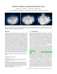
Introduction to Haptic Render<strong>in</strong>gMiguel A. OtaduyM<strong>in</strong>g C. L<strong>in</strong>Department of <strong>Computer</strong> ScienceUniversity of North Carol<strong>in</strong>a at Chapel Hill1 Why Haptic Render<strong>in</strong>g?For a long time, human be<strong>in</strong>gs have dreamed of a virtual world where it is possible to <strong>in</strong>teract with syntheticentities as if they were real. To date, the <strong>advances</strong> <strong>in</strong> computer graphics allow us to see virtual objects<strong>and</strong> avatars, to hear them, to move them, <strong>and</strong> to touch them. It has been shown that the ability to touchvirtual objects <strong>in</strong>creases the sense of presence <strong>in</strong> virtual environments [Insko 2001].Haptic render<strong>in</strong>g offers important applicability <strong>in</strong> eng<strong>in</strong>eer<strong>in</strong>g <strong>and</strong> medical tra<strong>in</strong><strong>in</strong>g tasks. In this chapterwe <strong>in</strong>troduce the concept of <strong>haptic</strong> render<strong>in</strong>g, <strong>and</strong> we briefly describe some of the basic techniques <strong>and</strong><strong>applications</strong>. In the first section we def<strong>in</strong>e some term<strong>in</strong>ology, discuss the evolution of the research <strong>in</strong> <strong>haptic</strong>render<strong>in</strong>g, <strong>and</strong> <strong>in</strong>troduce practical <strong>applications</strong>.1.1 Def<strong>in</strong>itionsThe term <strong>haptic</strong> (from the Greek haptesthai, mean<strong>in</strong>g “to touch”) is the adjective used to describe someth<strong>in</strong>grelat<strong>in</strong>g to or based on the sense of touch. Haptic is to touch<strong>in</strong>g as visual is to see<strong>in</strong>g <strong>and</strong> as auditory isto hear<strong>in</strong>g [Fisher et al. 2004].As described by Klatzky <strong>and</strong> Lederman [Klatzky <strong>and</strong> Lederman 2003], touch is one of the ma<strong>in</strong> avenues ofsensation, <strong>and</strong> it can be divided <strong>in</strong>to cutaneous, k<strong>in</strong>esthetic, <strong>and</strong> <strong>haptic</strong> systems, based on the underly<strong>in</strong>gneural <strong>in</strong>puts. The cutaneous system employs receptors embedded <strong>in</strong> the sk<strong>in</strong>, while the k<strong>in</strong>estheticsystem employs receptors located <strong>in</strong> muscles, tendons, <strong>and</strong> jo<strong>in</strong>ts. The <strong>haptic</strong> sensory system employsboth cutaneous <strong>and</strong> k<strong>in</strong>esthetic receptors, but it differs <strong>in</strong> the sense that it is associated with an activeprocedure. Touch becomes active when the sensory <strong>in</strong>puts are comb<strong>in</strong>ed with controlled body motion. Forexample, cutaneous touch becomes active when we explore a surface or grasp an object, while k<strong>in</strong>esthetictouch becomes active when we manipulate an object <strong>and</strong> touch other objects with it.Haptic render<strong>in</strong>g is def<strong>in</strong>ed as the process of comput<strong>in</strong>g <strong>and</strong> generat<strong>in</strong>g forces <strong>in</strong> response to user <strong>in</strong>teractionswith virtual objects [Salisbury et al. 1995]. Several <strong>haptic</strong> render<strong>in</strong>g algorithms consider the paradigmof touch<strong>in</strong>g virtual objects with a s<strong>in</strong>gle contact po<strong>in</strong>t. Render<strong>in</strong>g algorithms that follow this descriptionare called 3-DoF <strong>haptic</strong> render<strong>in</strong>g algorithms, because a po<strong>in</strong>t <strong>in</strong> 3D has only three DoFs. Other <strong>haptic</strong>render<strong>in</strong>g algorithms deal with the problem of render<strong>in</strong>g the forces <strong>and</strong> torques aris<strong>in</strong>g from the <strong>in</strong>teractionof two virtual objects. This problem is called 6-DoF <strong>haptic</strong> render<strong>in</strong>g, because the grasped object has sixDoFs (position <strong>and</strong> orientation <strong>in</strong> 3D), <strong>and</strong> the <strong>haptic</strong> feedback comprises 3D force <strong>and</strong> torque. When weeat with a fork, write with a pen, or open a lock with a key, we are mov<strong>in</strong>g an object <strong>in</strong> 3D, <strong>and</strong> we feelthe <strong>in</strong>teraction with other objects. This is, <strong>in</strong> essence, 6-DoF object manipulation with force-<strong>and</strong>-torquefeedback. Fig. 1 shows an example of a user experienc<strong>in</strong>g <strong>haptic</strong> render<strong>in</strong>g. When we manipulate an object<strong>and</strong> touch other objects with it, we perceive cutaneous feedback as the result of grasp<strong>in</strong>g, <strong>and</strong> k<strong>in</strong>estheticfeedback as the result of contact between objects.A3
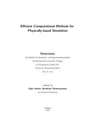
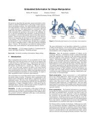
1 WHY HAPTIC RENDERING? 2Figure 1: Example of Haptic Render<strong>in</strong>g. A person manipulates a virtual jaw us<strong>in</strong>g a <strong>haptic</strong> device(shown on the right of the image), <strong>and</strong> the <strong>in</strong>teraction between jaws is displayed both visually <strong>and</strong> <strong>haptic</strong>ally.1.2 From Telerobotics to Haptic Render<strong>in</strong>gIn 1965, Ivan Sutherl<strong>and</strong> [Sutherl<strong>and</strong> 1965] proposed a multimodal display that would <strong>in</strong>corporate <strong>haptic</strong>feedback <strong>in</strong>to the <strong>in</strong>teraction with virtual worlds. Before that, <strong>haptic</strong> feedback had already been used ma<strong>in</strong>ly<strong>in</strong> two <strong>applications</strong>: flight simulators <strong>and</strong> master-slave robotic teleoperation. The early teleoperator systemshad mechanical l<strong>in</strong>kages between the master <strong>and</strong> the slave. But, <strong>in</strong> 1954, Goertz <strong>and</strong> Thompson [Goertz<strong>and</strong> Thompson 1954] developed an electrical servomechanism that received feedback signals from sensorsmounted on the slave <strong>and</strong> applied forces to the master, thus produc<strong>in</strong>g <strong>haptic</strong> feedback.From there, <strong>haptic</strong> <strong>in</strong>terfaces evolved <strong>in</strong> multiple directions, but there were two major breakthroughs.The first breakthrough was the idea of substitut<strong>in</strong>g the slave robot by a simulated system, <strong>in</strong> whichforces were computed us<strong>in</strong>g physically based simulations. The GROPE project at the University of NorthCarol<strong>in</strong>a at Chapel Hill [Brooks, Jr. et al. 1990], last<strong>in</strong>g from 1967 to 1990, was the first one to addressthe synthesis of force feedback from simulated <strong>in</strong>teractions. In particular, the aim of the project was toperform real-time simulation of 3D molecular-dock<strong>in</strong>g forces. The second breakthrough was the adventof computer-based Cartesian control for teleoperator systems [Bejczy <strong>and</strong> Salisbury 1980], enabl<strong>in</strong>g aseparation of the k<strong>in</strong>ematic configurations of the master <strong>and</strong> the slave. Later, Cartesian control wasapplied to the manipulation of simulated slave robots [Kim <strong>and</strong> Bejczy 1991].Those first <strong>haptic</strong> systems were able to simulate the <strong>in</strong>teraction of simple virtual objects only. Perhaps thefirst project to target computation of forces <strong>in</strong> the <strong>in</strong>teraction with objects with rich geometric <strong>in</strong>formationwas M<strong>in</strong>sky’s S<strong>and</strong>paper [M<strong>in</strong>sky et al. 1990]. M<strong>in</strong>sky et al. developed a planar force feedback system thatallowed the exploration of textures. A few years after M<strong>in</strong>sky’s work, Zilles <strong>and</strong> Salisbury presented analgorithm for 3-DoF <strong>haptic</strong> render<strong>in</strong>g of polygonal models [Zilles <strong>and</strong> Salisbury 1995]. Almost <strong>in</strong> parallelwith Zilles <strong>and</strong> Salisbury’s work, Massie <strong>and</strong> Salisbury [Massie <strong>and</strong> Salisbury 1994] designed the PHANToM,a stylus-based <strong>haptic</strong> <strong>in</strong>terface that was later commercialized <strong>and</strong> has become one of the most commonlyused force-feedback devices. But <strong>in</strong> the late ’90s, research <strong>in</strong> <strong>haptic</strong> render<strong>in</strong>g revived one of the problemsthat first <strong>in</strong>spired virtual force feedback: 6-DoF <strong>haptic</strong> render<strong>in</strong>g or, <strong>in</strong> other words, grasp<strong>in</strong>g of a virtualobject <strong>and</strong> synthesis of k<strong>in</strong>esthetic feedback of the <strong>in</strong>teraction between this object <strong>and</strong> its environment.A4
1 WHY HAPTIC RENDERING? 3Research <strong>in</strong> the field of <strong>haptic</strong>s <strong>in</strong> the last 35 years has covered many more areas than what we havesummarized here. [Burdea 1996] gives a general survey of the field of <strong>haptic</strong>s <strong>and</strong> [McLaughl<strong>in</strong> et al. 2002]discuss current research topics.1.3 Haptic Render<strong>in</strong>g for Virtual ManipulationCerta<strong>in</strong> professional activities, such as tra<strong>in</strong><strong>in</strong>g for high-risk operations or pre-production prototype test<strong>in</strong>g,can benefit greatly from simulated reproductions. The fidelity of the simulated reproductions depends,among other factors, on the similarity of the behaviors of real <strong>and</strong> virtual objects. In the real world,solid objects cannot <strong>in</strong>terpenetrate. Contact forces can be <strong>in</strong>terpreted mathematically as constra<strong>in</strong>t forcesimposed by penetration constra<strong>in</strong>ts. However, unless penetration constra<strong>in</strong>ts are explicitly imposed, virtualobjects are free to penetrate each other <strong>in</strong> virtual environments. Indeed, one of the most disconcert<strong>in</strong>gexperiences <strong>in</strong> virtual environments is to pass through virtual objects [Insko et al. 2001; Slater <strong>and</strong> Usoh1993]. Virtual environments require the simulation of non-penetrat<strong>in</strong>g rigid body dynamics, <strong>and</strong> thisproblem has been extensively explored <strong>in</strong> the robotics <strong>and</strong> computer graphics literature [Baraff 1992;Mirtich 1996].It has been shown that be<strong>in</strong>g able to touch physical replicas of virtual objects (a technique known aspassive <strong>haptic</strong>s [Insko 2001]) <strong>in</strong>creases the sense of presence <strong>in</strong> virtual environments. This conclusion canprobably be generalized to the case of synthetic cutaneous feedback of the <strong>in</strong>teraction with virtual objects.As reported by Brooks et al. [Brooks, Jr. et al. 1990], k<strong>in</strong>esthetic feedback radically improved situationawareness <strong>in</strong> virtual 3D molecular dock<strong>in</strong>g. K<strong>in</strong>esthetic feedback has proved to enhance task performance<strong>in</strong> <strong>applications</strong> such as telerobotic object assembly [Hill <strong>and</strong> Salisbury 1977], virtual object assembly [Ungeret al. 2002], <strong>and</strong> virtual molecular dock<strong>in</strong>g [Ouh-Young 1990]. In particular, task completion time is shorterwith k<strong>in</strong>esthetic feedback <strong>in</strong> dock<strong>in</strong>g operations but not <strong>in</strong> preposition<strong>in</strong>g operations.To summarize, <strong>haptic</strong> render<strong>in</strong>g is especially useful <strong>in</strong> particular examples of tra<strong>in</strong><strong>in</strong>g for high-risk operationsor pre-production prototype test<strong>in</strong>g activities that <strong>in</strong>volve <strong>in</strong>tensive object manipulation <strong>and</strong> <strong>in</strong>teractionwith the environment. Such examples <strong>in</strong>clude m<strong>in</strong>imally <strong>in</strong>vasive or endoscopic surgery [Edmondet al. 1997; Hayward et al. 1998] <strong>and</strong> virtual prototyp<strong>in</strong>g for assembly <strong>and</strong> ma<strong>in</strong>ta<strong>in</strong>ability assessment [Mc-Neely et al. 1999; Chen 1999; Andriot 2002; Wan <strong>and</strong> McNeely 2003]. Force feedback becomes particularlyimportant <strong>and</strong> useful <strong>in</strong> situations with limited visual feedback.1.4 3-DoF <strong>and</strong> 6-DoF Haptic Render<strong>in</strong>gMuch of the exist<strong>in</strong>g work <strong>in</strong> <strong>haptic</strong> render<strong>in</strong>g has focused on 3-DoF <strong>haptic</strong> render<strong>in</strong>g [Zilles <strong>and</strong> Salisbury1995; Rusp<strong>in</strong>i et al. 1997; Thompson et al. 1997; Gregory et al. 1999; Ho et al. 1999]. Given a virtual objectA <strong>and</strong> the 3D position of a po<strong>in</strong>t p governed by an <strong>in</strong>put device, 3-DoF <strong>haptic</strong> render<strong>in</strong>g can be summarizedas f<strong>in</strong>d<strong>in</strong>g a contact po<strong>in</strong>t p ′ constra<strong>in</strong>ed to the surface of A. The contact force will be computed as afunction of p <strong>and</strong> p ′ . In a dynamic sett<strong>in</strong>g, <strong>and</strong> assum<strong>in</strong>g that A is a polyhedron with n triangles,the problem of f<strong>in</strong>d<strong>in</strong>g p ′ has an O(n) worst-case complexity. Us<strong>in</strong>g spatial partition<strong>in</strong>g strategies <strong>and</strong>exploit<strong>in</strong>g motion coherence, however, the complexity becomes O(1) <strong>in</strong> many practical situations [Gregoryet al. 1999].This reduced complexity has made 3-DoF <strong>haptic</strong> render<strong>in</strong>g an attractive solution for many <strong>applications</strong>with virtual <strong>haptic</strong> feedback, such as: sculpt<strong>in</strong>g <strong>and</strong> deformation [Dachille et al. 1999; Gregory et al. 2000a;McDonnell et al. 2001], pa<strong>in</strong>t<strong>in</strong>g [Johnson et al. 1999; Gregory et al. 2000a; Foskey et al. 2002], volumevisualization [Avila <strong>and</strong> Sobierajski 1996], nanomanipulation [Taylor et al. 1993], <strong>and</strong> tra<strong>in</strong><strong>in</strong>g for diversesurgical operations [Kuhnapfel et al. 1997; Gibson et al. 1997]. In each of these <strong>applications</strong>, the <strong>in</strong>teractionbetween the subject <strong>and</strong> the virtual objects is sufficiently captured by a po<strong>in</strong>t-surface contact model.In 6-DoF manipulation <strong>and</strong> exploration, however, when a subject grasps an object <strong>and</strong> touches otherobjects <strong>in</strong> the environment, the <strong>in</strong>teraction generally cannot be modeled by a po<strong>in</strong>t-surface contact. Onereason is the existence of multiple contacts that impose multiple simultaneous non-penetration constra<strong>in</strong>tsA5
2 THE CHALLENGES 4on the grasped object. In a simple 6-DoF manipulation example, such as the <strong>in</strong>sertion of a peg <strong>in</strong> a hole,the grasped object (i.e., the peg) collides at multiple po<strong>in</strong>ts with the rest of the scene (i.e., the walls ofthe hole <strong>and</strong> the surround<strong>in</strong>g surface). This contact configuration cannot be modeled as a po<strong>in</strong>t-objectcontact. Another reason is that the grasped object presents six DoFs, 3D translation <strong>and</strong> rotation, asopposed to the three DoFs of a po<strong>in</strong>t. The feasible trajectories of the peg are embedded <strong>in</strong> a 6-dimensionalspace with translational <strong>and</strong> rotational constra<strong>in</strong>ts, that cannot be captured with three DoFs.Note that some cases of object-object <strong>in</strong>teraction have been modeled <strong>in</strong> practice by ray-surface contact[Basdogan et al. 1997]. In particular, several surgical procedures are performed with 4-DoF tools (e.g.,laparoscopy), <strong>and</strong> this constra<strong>in</strong>t has been exploited <strong>in</strong> tra<strong>in</strong><strong>in</strong>g simulators with <strong>haptic</strong> feedback [Çavuşoğluet al. 2002]. Nevertheless, these approximations are valid only <strong>in</strong> a limited number of situations <strong>and</strong> cannotcapture full 6-DoF object manipulation.2 The ChallengesHaptic render<strong>in</strong>g is <strong>in</strong> essence an <strong>in</strong>teractive activity, <strong>and</strong> its realization is mostly h<strong>and</strong>icapped by twoconflict<strong>in</strong>g challenges: high required update rates <strong>and</strong> the computational cost. In this section we outl<strong>in</strong>ethe computational pipel<strong>in</strong>e of <strong>haptic</strong> render<strong>in</strong>g, <strong>and</strong> we discuss associated challenges.2.1 Haptic Render<strong>in</strong>g Pipel<strong>in</strong>eHaptic render<strong>in</strong>g comprises two ma<strong>in</strong> tasks. One of them is the computation of the position <strong>and</strong>/ororientation of the virtual probe grasped by the user. The other one is the computation of contact force<strong>and</strong>/or torque that are fed back to the user. The exist<strong>in</strong>g methods for <strong>haptic</strong> render<strong>in</strong>g can be classified<strong>in</strong>to two large groups based on their overall pipel<strong>in</strong>es.In direct render<strong>in</strong>g methods [Nelson et al. 1999; Gregory et al. 2000b; Kim et al. 2003; Johnson <strong>and</strong>Willemsen 2003; Johnson <strong>and</strong> Willemsen 2004], the position <strong>and</strong>/or orientation of the <strong>haptic</strong> device areapplied directly to the grasped probe. Collision detection is performed between the grasped probe <strong>and</strong> thevirtual objects, <strong>and</strong> collision response is applied to the grasped probe as a function of object separation orpenetration depth. The result<strong>in</strong>g contact force <strong>and</strong>/or torque are directly fed back to the user.In virtual coupl<strong>in</strong>g methods [Chang <strong>and</strong> Colgate 1997; Berkelman 1999; McNeely et al. 1999; Rusp<strong>in</strong>i<strong>and</strong> Khatib 2000; Wan <strong>and</strong> McNeely 2003], the position <strong>and</strong>/or orientation of the <strong>haptic</strong> device are setas goals for the grasped probe, <strong>and</strong> a virtual viscoelastic coupl<strong>in</strong>g [Colgate et al. 1995] produces a forcethat attracts the grasped probe to its goals. Collision detection <strong>and</strong> response are performed between thegrasped probe <strong>and</strong> the virtual objects. The coupl<strong>in</strong>g force <strong>and</strong>/or torque are comb<strong>in</strong>ed with the collisionresponse <strong>in</strong> order to compute the position <strong>and</strong>/or orientation of the grasped probe. The same coupl<strong>in</strong>gforce <strong>and</strong>/or torque are fed back to the user.In Sec. 8, I describe the different exist<strong>in</strong>g methods for 6-DoF <strong>haptic</strong> render<strong>in</strong>g <strong>in</strong> more detail, <strong>and</strong> Idiscuss their advantages <strong>and</strong> disadvantages. Also, as expla<strong>in</strong>ed <strong>in</strong> more detail <strong>in</strong> Sec. 4, there are twomajor types of <strong>haptic</strong> devices, <strong>and</strong> for each type of device the render<strong>in</strong>g pipel<strong>in</strong>e presents slight variations.Impedance-type devices read the position <strong>and</strong> orientation of the h<strong>and</strong>le of the device <strong>and</strong> control the force<strong>and</strong> torque applied to the user. Admittance-type devices read the force <strong>and</strong> torque applied by the user<strong>and</strong> control the position <strong>and</strong> orientation of the h<strong>and</strong>le of the device.2.2 Force Update RateThe ultimate goal of <strong>haptic</strong> render<strong>in</strong>g is to provide force feedback to the user. This goal is achieved bycontroll<strong>in</strong>g the h<strong>and</strong>le of the <strong>haptic</strong> device, which is <strong>in</strong> fact the end-effector of a robotic manipulator. Whenthe user holds the h<strong>and</strong>le, he or she experiences k<strong>in</strong>esthetic feedback. The entire <strong>haptic</strong> render<strong>in</strong>g systemA6
2 THE CHALLENGES 5is regarded as a mechanical impedance that sets a transformation between the position <strong>and</strong> velocity of theh<strong>and</strong>le of the device <strong>and</strong> the applied force.The quality of <strong>haptic</strong> render<strong>in</strong>g can be measured <strong>in</strong> terms of the dynamic range of impedances that canbe simulated <strong>in</strong> a stable manner [Colgate <strong>and</strong> Brown 1994]. When the user moves the <strong>haptic</strong> device <strong>in</strong> freespace, the perceived impedance should be very low (i.e., small force), <strong>and</strong> when the grasped virtual objecttouches other rigid objects, the perceived impedance should be high (i.e., high stiffness <strong>and</strong>/or damp<strong>in</strong>gof the constra<strong>in</strong>t). The quality of <strong>haptic</strong> render<strong>in</strong>g can also be measured <strong>in</strong> terms of the responsiveness ofthe simulation [Brooks, Jr. et al. 1990; Berkelman 1999]. In free-space motion the grasped probe shouldrespond quickly to the motion of the user. Similarly, when the grasped probe collides with a virtual wall,the user should stop quickly, <strong>in</strong> response to the motion constra<strong>in</strong>t.With impedance-type devices, virtual walls are implemented as large stiffness values <strong>in</strong> the simulation.In <strong>haptic</strong> render<strong>in</strong>g, the user is part of a closed-loop sampled dynamic system [Colgate <strong>and</strong> Schenkel 1994],along with the device <strong>and</strong> the virtual environment, <strong>and</strong> the existence of sampl<strong>in</strong>g <strong>and</strong> latency phenomenacan <strong>in</strong>duce unstable behavior under large stiffness values. System <strong>in</strong>stability is directly perceived by theuser <strong>in</strong> the form of disturb<strong>in</strong>g oscillations. A key factor for achiev<strong>in</strong>g a high dynamic range of impedances(i.e., stiff virtual walls) while ensur<strong>in</strong>g stable render<strong>in</strong>g is the computation of feedback forces at a highupdate rate [Colgate <strong>and</strong> Schenkel 1994; Colgate <strong>and</strong> Brown 1994]. Brooks et al. [Brooks, Jr. et al. 1990]reported that, <strong>in</strong> the render<strong>in</strong>g of textured surfaces, users were able to perceive performance differences atforce update rates between 500Hz <strong>and</strong> 1kHz.A more detailed description of the stability issues <strong>in</strong>volved <strong>in</strong> the synthesis of force feedback, <strong>and</strong> adescription of related work, are given <strong>in</strong> Sec. 4. Although here we have focused on impedance-type <strong>haptic</strong>devices, similar conclusions can be drawn for admittance-type devices (See [Adams <strong>and</strong> Hannaford 1998]<strong>and</strong> Sec. 4).2.3 Contact Determ<strong>in</strong>ationThe computation of non-penetrat<strong>in</strong>g rigid-body dynamics of the grasped probe <strong>and</strong>, ultimately, synthesis of<strong>haptic</strong> feedback require a model of collision response. Forces between the virtual objects must be computedfrom contact <strong>in</strong>formation. Determ<strong>in</strong><strong>in</strong>g whether two virtual objects collide (i.e., <strong>in</strong>tersect) is not enough,<strong>and</strong> additional <strong>in</strong>formation, such as penetration distance, contact po<strong>in</strong>ts, contact normals, <strong>and</strong> so forth,need to be computed. Contact determ<strong>in</strong>ation describes the operation of obta<strong>in</strong><strong>in</strong>g the contact <strong>in</strong>formationnecessary for collision response [Baraff 1992].For two <strong>in</strong>teract<strong>in</strong>g virtual objects, collision response can be computed as a function of object separation,with worst-case cost O(mn), or penetration depth, with a complexity bound of Ω(m 3 n 3 ). But collisionresponse can also be applied at multiple contacts simultaneously. Given two objects A <strong>and</strong> B with m <strong>and</strong>n triangles respectively, contacts can be def<strong>in</strong>ed as pairs of <strong>in</strong>tersect<strong>in</strong>g triangles or pairs of triangles <strong>in</strong>sidea distance tolerance. The number of pairs of <strong>in</strong>tersect<strong>in</strong>g triangles is O(mn) <strong>in</strong> worst-case pathologicalcases, <strong>and</strong> the number of pairs of triangles <strong>in</strong>side a tolerance can be O(mn) <strong>in</strong> practical cases. In Sec. 5,we discuss <strong>in</strong> more detail exist<strong>in</strong>g techniques for determ<strong>in</strong><strong>in</strong>g the contact <strong>in</strong>formation.The cost of contact determ<strong>in</strong>ation depends largely on factors such as the convexity of the <strong>in</strong>teract<strong>in</strong>gobjects or the contact configuration. There is no direct connection between the polygonal complexityof the objects <strong>and</strong> the cost of contact determ<strong>in</strong>ation but, as a reference, exist<strong>in</strong>g exact collision detectionmethods can barely execute contact queries for force feedback between pairs of objects with 1, 000 triangles<strong>in</strong> complex contact scenarios [Kim et al. 2003] at force update rates of 1kHz.Contact determ<strong>in</strong>ation becomes particularly expensive <strong>in</strong> the <strong>in</strong>teraction between textured surfaces.Studies have been done on the highest texture resolution that can be perceived through cutaneous touch,but there are no clear results regard<strong>in</strong>g the highest resolution that can be perceived k<strong>in</strong>esthetically throughan <strong>in</strong>termediate object. It is known that, <strong>in</strong> the latter case, texture-<strong>in</strong>duced roughness perception is encoded<strong>in</strong> vibratory motion [Klatzky <strong>and</strong> Lederman 2002]. Psychophysics researchers report that 1mm texturesA7
3 PSYCHOPHYSICS OF HAPTICS 6are clearly perceivable, <strong>and</strong> perceived roughness appears to be even greater with f<strong>in</strong>er textures [Ledermanet al. 2000]. Based on Shannon’s sampl<strong>in</strong>g theorem, a 10cm × 10cm plate with a s<strong>in</strong>usoidal texture of1mm <strong>in</strong> orthogonal directions is barely correctly sampled with 40, 000 vertices. This measure gives an ideaof the triangulation density required for captur<strong>in</strong>g texture <strong>in</strong>formation of complex textured objects. Notethat the triangulation density may grow by orders of magnitude if the textures are not s<strong>in</strong>usoidal <strong>and</strong>/orif <strong>in</strong>formation about normals <strong>and</strong> curvatures is also needed.3 Psychophysics of HapticsIn the design of contact determ<strong>in</strong>ation algorithms for <strong>haptic</strong> render<strong>in</strong>g, it is crucial to underst<strong>and</strong> thepsychophysics of touch <strong>and</strong> to account for perceptual factors. The structure <strong>and</strong> behavior of humantouch have been studied extensively <strong>in</strong> the field of psychology. The topics analyzed by researchers <strong>in</strong>cludecharacterization of sensory phenomena as well as cognitive <strong>and</strong> memory processes.Haptic perception of physical properties <strong>in</strong>cludes a first step of stimulus registration <strong>and</strong> communicationto the thalamus, followed by a second step of higher-level process<strong>in</strong>g. Perceptual measures can be orig<strong>in</strong>atedby <strong>in</strong>dividual mechanoreceptors but also by the <strong>in</strong>tegration of <strong>in</strong>puts from populations of differentsensory units [Klatzky <strong>and</strong> Lederman 2003]. Klatzky <strong>and</strong> Lederman [Klatzky <strong>and</strong> Lederman 2003] discussobject <strong>and</strong> surface properties that are perceived through the sense of touch (e.g., texture, hardness, <strong>and</strong>weight) <strong>and</strong> divide them between geometric <strong>and</strong> material properties. They also analyze active exploratoryprocedures (e.g., lateral motion, pressure, or unsupported hold<strong>in</strong>g) typically conducted by subjects <strong>in</strong> orderto capture <strong>in</strong>formation about the different properties.Know<strong>in</strong>g the exploratory procedure(s) associated with a particular object or surface property, researchershave studied the <strong>in</strong>fluence of various parameters on the accuracy <strong>and</strong> magnitude of sensory outputs.Perceptual studies on tactile feature detection <strong>and</strong> identification, as well as studies on texture or roughnessperception are of particular <strong>in</strong>terest for <strong>haptic</strong> render<strong>in</strong>g. In this section we summarize exist<strong>in</strong>g researchon perception of surface features <strong>and</strong> perception of roughness, <strong>and</strong> then we discuss issues associated withthe <strong>in</strong>teraction of visual <strong>and</strong> <strong>haptic</strong> modalities.3.1 Perception of Surface FeaturesKlatzky <strong>and</strong> Lederman describe two different exploratory procedures followed by subjects <strong>in</strong> order tocapture shape attributes <strong>and</strong> identify features <strong>and</strong> objects. In <strong>haptic</strong> glance [Klatzky <strong>and</strong> Lederman 1995],subjects extract <strong>in</strong>formation from a brief <strong>haptic</strong> exposure of the object surface. Then they perform higherlevelprocess<strong>in</strong>g for determ<strong>in</strong><strong>in</strong>g the identity of the object or other attributes. In contour follow<strong>in</strong>g [Klatzky<strong>and</strong> Lederman 2003], subjects create a spatiotemporal map of surface attributes, such as curvature, thatserves as the pattern for feature identification. Contact determ<strong>in</strong>ation algorithms attempt to describethe geometric <strong>in</strong>teraction between virtual objects. The <strong>in</strong>stantaneous nature of <strong>haptic</strong> glance [Klatzky<strong>and</strong> Lederman 1995] makes it strongly dependent on purely geometric attributes, unlike the temporaldependency of contour follow<strong>in</strong>g.Klatzky <strong>and</strong> Lederman [Klatzky <strong>and</strong> Lederman 1995] conducted experiments <strong>in</strong> which subjects were<strong>in</strong>structed to identify objects from brief cutaneous exposures (i.e., <strong>haptic</strong> glances). Subjects had an advancehypothesis of the nature of the object. The purpose of the study was to discover how, <strong>and</strong> how well, subjectsidentify objects from brief contact. Accord<strong>in</strong>g to Klatzky <strong>and</strong> Lederman, dur<strong>in</strong>g <strong>haptic</strong> glance a subjecthas access to three pieces of <strong>in</strong>formation: roughness, compliance, <strong>and</strong> local features. Roughness <strong>and</strong>compliance are material properties that can be extracted from lower-level process<strong>in</strong>g, while local featurescan lead to object identification by feature match<strong>in</strong>g dur<strong>in</strong>g higher-level process<strong>in</strong>g. In the experiments,highest identification accuracy was achieved with small objects, whose shapes fit on a f<strong>in</strong>gertip. Klatzky <strong>and</strong>Lederman concluded that large contact area helped <strong>in</strong> the identification of textures or patterns, although itwas better to have a stimulus of a size comparable to or just slightly smaller than that of the contact areaA8
3 PSYCHOPHYSICS OF HAPTICS 7for the identification of geometric surface features. The experiments conducted by Klatzky <strong>and</strong> Ledermanposit an <strong>in</strong>terest<strong>in</strong>g relation between feature size <strong>and</strong> contact area dur<strong>in</strong>g cutaneous perception.Okamura <strong>and</strong> Cutkosky [Okamura <strong>and</strong> Cutkosky 1999; Okamura <strong>and</strong> Cutkosky 2001] analyzed featuredetection <strong>in</strong> robotic exploration, which can be regarded as a case of object-object <strong>in</strong>teraction. Theycharacterized geometric surface features based on the ratios of their curvatures to the radii of the roboticf<strong>in</strong>gertips acquir<strong>in</strong>g the surface data. They observed that a larger f<strong>in</strong>gertip, which provides a larger contactarea, can miss small geometric features. To summarize, the studies by Klatzky <strong>and</strong> Lederman [Klatzky<strong>and</strong> Lederman 1995] <strong>and</strong> Okamura <strong>and</strong> Cutkosky [Okamura <strong>and</strong> Cutkosky 1999; Okamura <strong>and</strong> Cutkosky2001] lead to the observation that human <strong>haptic</strong> perception of the existence of a geometric surface featuredepends on the ratio between the contact area <strong>and</strong> the size of the feature, not the absolute size of thefeature itself. This observation has driven the design of multiresolution contact determ<strong>in</strong>ation algorithmsfor <strong>haptic</strong> render<strong>in</strong>g [Otaduy <strong>and</strong> L<strong>in</strong> 2003b].3.2 Perception of Texture <strong>and</strong> RoughnessKlatzky <strong>and</strong> Lederman [Klatzky <strong>and</strong> Lederman 2003] describe a textured surface as a surface with protuberantelements aris<strong>in</strong>g from a relatively homogeneous substrate. Interaction with a textured surfaceresults <strong>in</strong> perception of roughness. Exist<strong>in</strong>g research on the psychophysics of texture perception <strong>in</strong>dicates aclear dichotomy of exploratory procedures: (a) perception of texture with the bare sk<strong>in</strong>, <strong>and</strong> (b) perceptionthrough an <strong>in</strong>termediate (rigid) object, a probe.Most of the research efforts have been directed towards the characterization of cutaneous perceptionof textures. Katz [Katz 1989] suggested that roughness is perceived through a comb<strong>in</strong>ation of spatial<strong>and</strong> vibratory codes dur<strong>in</strong>g direct <strong>in</strong>teraction with the sk<strong>in</strong>. More <strong>recent</strong> evidence demonstrates thatstatic pressure distribution plays a dom<strong>in</strong>ant role <strong>in</strong> perception of coarse textures (features larger than1mm) [Lederman 1974; Connor <strong>and</strong> Johnson 1992], but motion-<strong>in</strong>duced vibration is necessary for perceiv<strong>in</strong>gf<strong>in</strong>e textures [LaMotte <strong>and</strong> Sr<strong>in</strong>ivasan 1991; Holl<strong>in</strong>s <strong>and</strong> Risner 2000].As po<strong>in</strong>ted out by Klatzky <strong>and</strong> Lederman [Klatzky <strong>and</strong> Lederman 2002], <strong>in</strong> object-object <strong>in</strong>teractionroughness is encoded <strong>in</strong> vibratory motion transmitted to the subject. In the last few years, Klatzky <strong>and</strong>Lederman have directed experiments that analyze the <strong>in</strong>fluence of several factors on roughness perceptionthrough a rigid probe. Klatzky et al. [Klatzky et al. 2003] dist<strong>in</strong>guished three types of factors that may affectthe perceived magnitude of roughness: <strong>in</strong>terobject physical <strong>in</strong>teraction, sk<strong>in</strong>- <strong>and</strong> limb-<strong>in</strong>duced filter<strong>in</strong>gprior to cutaneous <strong>and</strong> k<strong>in</strong>esthetic perception, <strong>and</strong> higher-level factors such as efferent comm<strong>and</strong>s. Thedesign of contact determ<strong>in</strong>ation <strong>and</strong> collision response algorithms for <strong>haptic</strong> texture render<strong>in</strong>g is mostlyconcerned with factors related to the physical <strong>in</strong>teraction between objects: object geometry [Ledermanet al. 2000; Klatzky et al. 2003], applied force [Lederman et al. 2000], <strong>and</strong> exploratory speed [Ledermanet al. 1999; Klatzky et al. 2003]. The <strong>in</strong>fluence of these factors has been addressed <strong>in</strong> the design of <strong>haptic</strong>texture render<strong>in</strong>g algorithms [Otaduy et al. 2004].The experiments conducted by Klatzky <strong>and</strong> Lederman to characterize roughness perception [Klatzky <strong>and</strong>Lederman 2002] used a common setup: subjects explored a textured plate with a probe with a sphericaltip, <strong>and</strong> then they reported a subjective measure of roughness. Plates of jittered raised dots were used,<strong>and</strong> the mean frequency of dot distribution was one of the variables <strong>in</strong> the experiments. The result<strong>in</strong>g datawas analyzed by plott<strong>in</strong>g subjective roughness values vs. dot <strong>in</strong>terspac<strong>in</strong>g <strong>in</strong> logarithmic graphs.Klatzky <strong>and</strong> Lederman [Klatzky <strong>and</strong> Lederman 1999] compared graphs of roughness vs. texture spac<strong>in</strong>g(a) with f<strong>in</strong>ger exploration <strong>and</strong> (b) with a rigid probe. They concluded that, <strong>in</strong> the range of their data,roughness functions were best fit by l<strong>in</strong>ear approximations <strong>in</strong> f<strong>in</strong>ger exploration <strong>and</strong> by quadratic approximations<strong>in</strong> probe-based exploration. In other words, when perceived through a rigid spherical probe,roughness <strong>in</strong>itially <strong>in</strong>creases as texture spac<strong>in</strong>g <strong>in</strong>creases, but, after reach<strong>in</strong>g a maximum roughness value,it decreases aga<strong>in</strong>. Based on this f<strong>in</strong>d<strong>in</strong>g, the <strong>in</strong>fluence of other factors on roughness perception can becharacterized by the maximum value of roughness <strong>and</strong> the value of texture spac<strong>in</strong>g at which this maximumA9
4 STABILITY AND CONTROL THEORY APPLIED TO HAPTIC RENDERING 8takes place.Lederman et al. [Lederman et al. 2000] demonstrated that the diameter of the spherical probe playsa crucial role <strong>in</strong> the maximum value of perceived roughness <strong>and</strong> the location of the maximum. Theroughness peak is higher for smaller probes, <strong>and</strong> it occurs at smaller texture spac<strong>in</strong>g values. Ledermanet al. [Lederman et al. 2000] also studied the <strong>in</strong>fluence of the applied normal force dur<strong>in</strong>g exploration.Roughness is higher for larger force, but the <strong>in</strong>fluence on the location of the peak is negligible. The effectof exploratory speed was studied by Lederman et al. [Lederman et al. 1999]. They found that the peak ofroughness occurs at larger texture spac<strong>in</strong>g for higher speed. Also, with higher speed, textured plates feelsmoother at small texture spac<strong>in</strong>g, <strong>and</strong> rougher at large spac<strong>in</strong>g values. The studies reflected that speedhas a stronger effect <strong>in</strong> passive <strong>in</strong>teraction than <strong>in</strong> active <strong>in</strong>teraction.3.3 Haptic <strong>and</strong> Visual Cross-modal InteractionHaptic render<strong>in</strong>g is often presented along with visual display. Therefore, it is important to underst<strong>and</strong> theissues <strong>in</strong>volved <strong>in</strong> cross-modal <strong>in</strong>teraction. Klatzky <strong>and</strong> Lederman [Klatzky <strong>and</strong> Lederman 2003] discussaspects of visual <strong>and</strong> <strong>haptic</strong> cross-modal <strong>in</strong>tegration from two perspectives: attention <strong>and</strong> dom<strong>in</strong>ance.Spence et al. [Spence et al. 2000] have studied how visual <strong>and</strong> tactile cues can <strong>in</strong>fluence a subject’sattention. Their conclusions are that visual <strong>and</strong> tactile cues are treated together <strong>in</strong> a s<strong>in</strong>gle attentionalmechanism, <strong>and</strong> wrong attention cues can affect perception negatively.Sensory dom<strong>in</strong>ance is usually studied by analyz<strong>in</strong>g perceptual discrepancies <strong>in</strong> situations where crossmodal<strong>in</strong>tegration yields a unitary perceptual response. One example of relevance for this dissertationis the detection of object collision. Dur<strong>in</strong>g object manipulation, humans determ<strong>in</strong>e whether two objectsare <strong>in</strong> contact based on a comb<strong>in</strong>ation of visual <strong>and</strong> <strong>haptic</strong> cues. Early studies of sensory dom<strong>in</strong>anceseemed to po<strong>in</strong>t to a strong dom<strong>in</strong>ance of visual cues over <strong>haptic</strong> cues [Rock <strong>and</strong> Victor 1964], but <strong>in</strong> thelast decades psychologists agree that sensory <strong>in</strong>puts are weighted based on their statistical reliability orrelative appropriateness, measured <strong>in</strong> terms of accuracy, precision, <strong>and</strong> cue availability [Heller et al. 1999;Ernst <strong>and</strong> Banks 2001; Klatzky <strong>and</strong> Lederman 2003].The design of contact determ<strong>in</strong>ation algorithms can also benefit from exist<strong>in</strong>g studies on the visualperception of collisions <strong>in</strong> computer animations. O’Sullivan <strong>and</strong> her colleagues [O’Sullivan et al. 1999;O’Sullivan <strong>and</strong> D<strong>in</strong>gliana 2001; O’Sullivan et al. 2003] have <strong>in</strong>vestigated different factors affect<strong>in</strong>g visualcollision perception, <strong>in</strong>clud<strong>in</strong>g eccentricity, separation, distractors, causality, <strong>and</strong> accuracy of simulationresults. Bas<strong>in</strong>g their work on a model of human visual perception validated by psychophysical experiments,they demonstrated the feasibility of us<strong>in</strong>g these factors for schedul<strong>in</strong>g <strong>in</strong>terruptible collision detection amonglarge numbers of visually homogeneous objects.4 Stability <strong>and</strong> Control Theory Applied to Haptic Render<strong>in</strong>gIn <strong>haptic</strong> render<strong>in</strong>g, the human user is part of the dynamic system, along with the <strong>haptic</strong> device <strong>and</strong>the computer implementation of the virtual environment. The complete human-<strong>in</strong>-the-loop system canbe regarded as a sampled-data system [Colgate <strong>and</strong> Schenkel 1994], with a cont<strong>in</strong>uous component (theuser <strong>and</strong> the device) <strong>and</strong> a discrete one (the implementation of the virtual environment <strong>and</strong> the devicecontroller). Stability becomes a crucial feature, because <strong>in</strong>stabilities <strong>in</strong> the system can produce oscillationsthat distort the perception of the virtual environment, or uncontrolled motion of the device that can evenhurt the user. In Sec. 2.2, we have briefly discussed the importance of stability for <strong>haptic</strong> render<strong>in</strong>g, <strong>and</strong>we have <strong>in</strong>troduced the effect of the force update rate on stability. In this section we review <strong>and</strong> discuss<strong>in</strong> more detail exist<strong>in</strong>g work <strong>in</strong> control theory related to stability analysis of <strong>haptic</strong> render<strong>in</strong>g.A10
4 STABILITY AND CONTROL THEORY APPLIED TO HAPTIC RENDERING 94.1 Mechanical Impedance ControlThe concept of mechanical impedance extends the notion of electrical impedance <strong>and</strong> refers to the quotientbetween force <strong>and</strong> velocity. Hogan [Hogan 1985] <strong>in</strong>troduced the idea of impedance control for contact tasks<strong>in</strong> manipulation. Earlier techniques controlled contact force, robot velocity, or both, but Hogan suggestedcontroll<strong>in</strong>g directly the mechanical impedance, which governs the dynamic properties of the system. Whenthe end effector of a robot touches a rigid surface, it suffers a drastic change of mechanical impedance,from low impedance <strong>in</strong> free space, to high impedance dur<strong>in</strong>g contact. This phenomenon imposes seriousdifficulties on earlier control techniques, <strong>in</strong>duc<strong>in</strong>g <strong>in</strong>stabilities.The function of a <strong>haptic</strong> device is to display the feedback force of a virtual world to a human user. Hapticdevices present control challenges very similar to those of manipulators for contact tasks. As <strong>in</strong>troduced<strong>in</strong> Sec. 2.1, there are two major ways of controll<strong>in</strong>g a <strong>haptic</strong> device: impedance control <strong>and</strong> admittancecontrol. In impedance control, the user moves the device, <strong>and</strong> the controller produces a force dependenton the <strong>in</strong>teraction <strong>in</strong> the virtual world. In admittance control, the user applies a force to the device, <strong>and</strong>the controller moves the device accord<strong>in</strong>g to the virtual <strong>in</strong>teraction.In both impedance <strong>and</strong> admittance control, high control ga<strong>in</strong>s can <strong>in</strong>duce <strong>in</strong>stabilities. In impedancecontrol, <strong>in</strong>stabilities may arise <strong>in</strong> the simulation of stiff virtual surfaces. The device must react withlarge changes <strong>in</strong> force to small changes <strong>in</strong> the position. Conversely, <strong>in</strong> admittance control, render<strong>in</strong>g astiff virtual surface is not a challeng<strong>in</strong>g problem, because it is implemented as a low controller ga<strong>in</strong>. Inadmittance control, however, <strong>in</strong>stabilities may arise dur<strong>in</strong>g free-space motion <strong>in</strong> the virtual world, becausethe device must move at high velocities under small applied forces, or when the device rests on a stiffphysical surface. Impedance <strong>and</strong> admittance control can therefore be regarded as complementary controltechniques, best suited for opposite <strong>applications</strong>. Follow<strong>in</strong>g the unify<strong>in</strong>g framework presented by Adams<strong>and</strong> Hannaford [Adams <strong>and</strong> Hannaford 1998], Contact determ<strong>in</strong>ation <strong>and</strong> force computation algorithmsare often <strong>in</strong>dependent of the control strategy.4.2 Stable Render<strong>in</strong>g of Virtual WallsS<strong>in</strong>ce the <strong>in</strong>troduction of impedance control by Hogan [Hogan 1985], the analysis of the stability of <strong>haptic</strong>devices <strong>and</strong> <strong>haptic</strong> render<strong>in</strong>g algorithms has focused on the problem of render<strong>in</strong>g stiff virtual walls. Thiswas known to be a complex problem at early stages of research <strong>in</strong> <strong>haptic</strong> render<strong>in</strong>g [Kilpatrick 1976], butimpedance control simplified the analysis, because a virtual wall can be modeled easily us<strong>in</strong>g stiffness <strong>and</strong>viscosity parameters.Ouh-Young [Ouh-Young 1990] created a discrete model of the Argonne ARM <strong>and</strong> the human arm <strong>and</strong>analyzed the <strong>in</strong>fluence of force update rate on the stability <strong>and</strong> responsiveness of the system. M<strong>in</strong>sky,Brooks, et al. [M<strong>in</strong>sky et al. 1990; Brooks, Jr. et al. 1990] observed that update rates as high as 500Hz or1kHz might be necessary <strong>in</strong> order to achieve stability.Colgate <strong>and</strong> Brown [Colgate <strong>and</strong> Brown 1994] co<strong>in</strong>ed the term Z-Width for describ<strong>in</strong>g the range ofmechanical impedances that a <strong>haptic</strong> device can render while guarantee<strong>in</strong>g stability. They concluded thatphysical dissipation is essential for achiev<strong>in</strong>g stability <strong>and</strong> that the maximum achievable virtual stiffnessis proportional to the update rate. They also analyzed the <strong>in</strong>fluence of position sensors <strong>and</strong> quantization,<strong>and</strong> concluded that sensor resolution must be maximized <strong>and</strong> the velocity signal must be filtered.Almost <strong>in</strong> parallel, Salcudean <strong>and</strong> Vlaar [Salcudean <strong>and</strong> Vlaar 1994] studied <strong>haptic</strong> render<strong>in</strong>g of virtualwalls, <strong>and</strong> techniques for improv<strong>in</strong>g the fidelity of the render<strong>in</strong>g. They compared a cont<strong>in</strong>uous model of avirtual wall with a discrete model that accounts for differentiation of the position signal. The cont<strong>in</strong>uousmodel is unconditionally stable, but this is not true for the discrete model. Moreover, <strong>in</strong> the discrete modelfast damp<strong>in</strong>g of contact oscillations is possible only with rather low contact stiffness <strong>and</strong>, as <strong>in</strong>dicated byColgate <strong>and</strong> Brown too [Colgate <strong>and</strong> Brown 1994], this value of stiffness is proportional to the updaterate. Salcudean <strong>and</strong> Vlaar proposed the addition of brak<strong>in</strong>g pulses, proportional to collision velocity, forimprov<strong>in</strong>g the perception of virtual walls.A11
4 STABILITY AND CONTROL THEORY APPLIED TO HAPTIC RENDERING 104.3 Passivity <strong>and</strong> Virtual Coupl<strong>in</strong>gA subsystem is passive if it does not add energy to the global system. Passivity is a powerful tool foranalyz<strong>in</strong>g stability of coupled systems, because the coupled system obta<strong>in</strong>ed from two passive subsystemsis always stable. Colgate <strong>and</strong> his colleagues were the first to apply passivity criteria to the analysis ofstability <strong>in</strong> <strong>haptic</strong> render<strong>in</strong>g of virtual walls [Colgate et al. 1993]. Passivity-based analysis has enabledseparate study of the behavior of the human subsystem, the <strong>haptic</strong> device, <strong>and</strong> the virtual environment <strong>in</strong>force-feedback systems.4.3.1 Human Sens<strong>in</strong>g <strong>and</strong> Control B<strong>and</strong>widthsHogan discovered that the human neuromuscular system exhibits externally simple, spr<strong>in</strong>glike behavior[Hogan 1986]. This f<strong>in</strong>d<strong>in</strong>g implies that the human arm hold<strong>in</strong>g a <strong>haptic</strong> device can be regarded as apassive subsystem, <strong>and</strong> the stability analysis can focus on the <strong>haptic</strong> device <strong>and</strong> the virtual environment.Note that human limbs are not passive <strong>in</strong> all conditions, but the b<strong>and</strong>width at which a subject canperform active motions is very low compared to the frequencies at which stability problems may arise.Some authors [Shimoga 1992; Burdea 1996] report that the b<strong>and</strong>width at which humans can performcontrolled actions with the h<strong>and</strong> or f<strong>in</strong>gers is between 5 <strong>and</strong> 10Hz. On the other h<strong>and</strong>, sens<strong>in</strong>g b<strong>and</strong>widthcan be as high as 20 to 30Hz for proprioception, 400Hz for tactile sens<strong>in</strong>g, <strong>and</strong> 5 to 10kHz for roughnessperception.4.3.2 Passivity of Virtual WallsColgate <strong>and</strong> Schenkel [Colgate <strong>and</strong> Schenkel 1994] observed that the oscillations perceived by a <strong>haptic</strong> userdur<strong>in</strong>g system <strong>in</strong>stability are a result of active behavior of the force-feedback system. This active behavioris a consequence of time delay <strong>and</strong> loss of <strong>in</strong>formation <strong>in</strong>herent <strong>in</strong> sampled-data systems, as suggested byothers before [Brooks, Jr. et al. 1990]. Colgate <strong>and</strong> Schenkel formulated passivity conditions <strong>in</strong> <strong>haptic</strong>render<strong>in</strong>g of a virtual wall. For that analysis, they modeled the virtual wall as a viscoelastic unilateralconstra<strong>in</strong>t, <strong>and</strong> they accounted for the cont<strong>in</strong>uous dynamics of the <strong>haptic</strong> device, sampl<strong>in</strong>g of the positionsignal, discrete differentiation for obta<strong>in</strong><strong>in</strong>g velocity, <strong>and</strong> a zero-order hold of the output force. Theyreached a sufficient condition for passivity that relates the stiffness K <strong>and</strong> damp<strong>in</strong>g B of the virtual wall,the <strong>in</strong>herent damp<strong>in</strong>g b of the device, <strong>and</strong> the sampl<strong>in</strong>g period T:b > KT2+ B. (1)4.3.3 Stability of Non-l<strong>in</strong>ear Virtual EnvironmentsAfter deriv<strong>in</strong>g stability conditions for render<strong>in</strong>g virtual walls modeled as unilateral l<strong>in</strong>ear constra<strong>in</strong>ts,Colgate <strong>and</strong> his colleagues considered more complex environments [Colgate et al. 1995]. A general virtualenvironment is non-l<strong>in</strong>ear, <strong>and</strong> it presents multiple <strong>and</strong> variable constra<strong>in</strong>ts. Their approach enforces adiscrete-time passive implementation of the virtual environment <strong>and</strong> sets a multidimensional viscoelasticvirtual coupl<strong>in</strong>g between the virtual environment <strong>and</strong> the <strong>haptic</strong> display. In this way, the stability of thesystem is guaranteed as long as the virtual coupl<strong>in</strong>g is itself passive, <strong>and</strong> this condition can be analyzed us<strong>in</strong>gthe same techniques as those used for virtual walls [Colgate <strong>and</strong> Schenkel 1994]. As a result of Colgate’svirtual coupl<strong>in</strong>g [Colgate et al. 1995], the complexity of the problem was shifted towards design<strong>in</strong>g a passivesolution of virtual world dynamics. As noted by Colgate et al. [Colgate et al. 1995], one possible way toenforce passivity <strong>in</strong> rigid body dynamics simulation is to use implicit <strong>in</strong>tegration with penalty methods.Adams <strong>and</strong> Hannaford [Adams <strong>and</strong> Hannaford 1998] provided a framework for analyz<strong>in</strong>g stability withadmittance-type <strong>and</strong> impedance-type <strong>haptic</strong> devices. They derived stability conditions for coupled systemsbased on network theory. They also extended the concept of virtual coupl<strong>in</strong>g to admittance-type devices.A12
5 COLLISION DETECTION 11Miller et al. [Miller et al. 1990] extended Colgate’s passivity analysis techniques, relax<strong>in</strong>g the requirementof passive virtual environments but enforc<strong>in</strong>g cyclo-passivity of the complete system. Hannaford <strong>and</strong> hiscolleagues [Hannaford et al. 2002] <strong>in</strong>vestigated the use of adaptive controllers <strong>in</strong>stead of the traditionalfixed-value virtual coupl<strong>in</strong>gs. They designed passivity observers <strong>and</strong> passivity controllers for dissipat<strong>in</strong>gthe excess of energy generated by the virtual environment.4.4 Multirate Approximation TechniquesMultirate approximation techniques, though simple, have been successful <strong>in</strong> improv<strong>in</strong>g the stability <strong>and</strong>responsiveness of <strong>haptic</strong> render<strong>in</strong>g systems. The idea is to perform a full update of the virtual environmentat a low frequency (limited by computational resources <strong>and</strong> the complexity of the system) <strong>and</strong> to use asimplified approximation for perform<strong>in</strong>g high-frequency updates of force feedback.Adachi [Adachi et al. 1995] proposed an <strong>in</strong>termediate representation for <strong>haptic</strong> display of complex polygonalobjects. In a slow collision detection thread, he computed a plane that served as a unilateral constra<strong>in</strong>t<strong>in</strong> the force-feedback thread. This technique was later adapted by Mark et al. [Mark et al. 1996], who<strong>in</strong>terpolated the <strong>in</strong>termediate representation between updates. This approach enables higher stiffness valuesthan approaches that compute the feedback force values at the rate imposed by collision detection.More <strong>recent</strong>ly, a similar multirate approach has been followed by many authors for <strong>haptic</strong> <strong>in</strong>teraction withdeformable models [Astley <strong>and</strong> Hayward 1998; Çavuşoğlu <strong>and</strong> Tendick 2000; Duriez et al. 2004]. Ellis etal. [Ellis et al. 1997] produce higher-quality render<strong>in</strong>g by upsampl<strong>in</strong>g directly the output force values.5 Collision DetectionCollision detection has received much attention <strong>in</strong> robotics, computational geometry, <strong>and</strong> computer graphics.Some researchers have <strong>in</strong>vestigated the problem of <strong>in</strong>terference detection as a mechanism for <strong>in</strong>dicat<strong>in</strong>gwhether object configurations are valid or not. Others have tackled the problems of comput<strong>in</strong>g separationor penetration distances, with the objective of apply<strong>in</strong>g collision response <strong>in</strong> simulated environments. Theexist<strong>in</strong>g work on collision detection can be classified based on the types of models h<strong>and</strong>led: 2-manifoldpolyhedral models, polygon soups, curved surfaces, etc. In this section we focus on collision detection forpolyhedral models. The vast majority of the algorithms used <strong>in</strong> practice proceed <strong>in</strong> two steps: first theycull large portions of the objects that are not <strong>in</strong> close proximity, us<strong>in</strong>g spatial partition<strong>in</strong>g, hierarchicaltechniques, or visibility-based properties, <strong>and</strong> then they perform primitive-level tests.In this section, we first describe the problems of <strong>in</strong>terference detection <strong>and</strong> computation of separationdistance between polyhedra, with an emphasis on algorithms specialized for convex polyhedra. Thenwe survey algorithms for the computation of penetration depth, the use of hierarchical techniques, <strong>and</strong>multiresolution collision detection. we conclude the section by cover<strong>in</strong>g briefly the use of graphics processorsfor collision detection <strong>and</strong> the topic of cont<strong>in</strong>uous collision detection. For more <strong>in</strong>formation on collisiondetection, please refer to surveys on the topic [L<strong>in</strong> <strong>and</strong> Gottschalk 1998; Klosowski et al. 1998; L<strong>in</strong> <strong>and</strong>Manocha 2004].5.1 Proximity Queries Between Convex PolyhedraThe property of convexity has been exploited <strong>in</strong> algorithms with subl<strong>in</strong>ear cost for detect<strong>in</strong>g <strong>in</strong>terferenceor comput<strong>in</strong>g the closest distance between two polyhedra. Detect<strong>in</strong>g whether two convex polyhedra <strong>in</strong>tersectcan be posed as a l<strong>in</strong>ear programm<strong>in</strong>g problem, search<strong>in</strong>g for the coefficients of a separat<strong>in</strong>g plane.Well-known l<strong>in</strong>ear programm<strong>in</strong>g algorithms [Seidel 1990] can run <strong>in</strong> expected l<strong>in</strong>ear time due to the lowdimensionality of the problem.The separation distance between two polyhedra A <strong>and</strong> B is equal to the distance from the orig<strong>in</strong> tothe M<strong>in</strong>kowski sum of A <strong>and</strong> −B [Cameron <strong>and</strong> Culley 1986]. This property was exploited by GilbertA13
5 COLLISION DETECTION 12et al. [Gilbert et al. 1988] <strong>in</strong> order to design a convex optimization algorithm (known as GJK) forcomput<strong>in</strong>g the separation distance between convex polyhedra, with l<strong>in</strong>ear-time performance <strong>in</strong> practice.Cameron [Cameron 1997] modified the GJK algorithm to exploit motion coherence <strong>in</strong> the <strong>in</strong>itialization ofthe convex optimization at every frame for dynamic problems, achiev<strong>in</strong>g nearly constant runn<strong>in</strong>g-time <strong>in</strong>practice.L<strong>in</strong> <strong>and</strong> Canny [L<strong>in</strong> <strong>and</strong> Canny 1991; L<strong>in</strong> 1993] designed an algorithm for comput<strong>in</strong>g separation distanceby track<strong>in</strong>g the closest features between convex polyhedra. Their algorithm “walks” on the surfaces of thepolyhedra until it f<strong>in</strong>ds two features that lie on each other’s Voronoi region. Exploit<strong>in</strong>g motion coherence<strong>and</strong> geometric locality, Voronoi march<strong>in</strong>g runs <strong>in</strong> nearly constant time per frame. Mirtich [Mirtich 1998b]later improved the robustness of this algorithm.Given polyhedra A <strong>and</strong> B with m <strong>and</strong> n polygons respectively, Dobk<strong>in</strong> <strong>and</strong> Kirkpatrick [Dobk<strong>in</strong> <strong>and</strong>Kirkpatrick 1990] proposed an algorithm for <strong>in</strong>terference detection with O(log m log n) time complexitythat uses hierarchical representations of the polyhedra. Others have also exploited the use of hierarchicalconvex representations along with temporal coherence <strong>in</strong> order to accelerate queries <strong>in</strong> dynamic scenes.Guibas et al. [Guibas et al. 1999] employ the <strong>in</strong>ner hierarchies suggested by Dobk<strong>in</strong> <strong>and</strong> Kirkpatrick,but they perform faster multilevel walk<strong>in</strong>g. Ehmann <strong>and</strong> L<strong>in</strong> [Ehmann <strong>and</strong> L<strong>in</strong> 2000] employ a modifiedversion of Dobk<strong>in</strong> <strong>and</strong> Kirkpatrick’s outer hierarchies, computed us<strong>in</strong>g simplification techniques, along witha multilevel implementation of L<strong>in</strong> <strong>and</strong> Canny’s Voronoi march<strong>in</strong>g [L<strong>in</strong> <strong>and</strong> Canny 1991].5.2 Penetration DepthThe penetration depth between two <strong>in</strong>tersect<strong>in</strong>g polyhedra A <strong>and</strong> B is def<strong>in</strong>ed as the m<strong>in</strong>imum translationaldistance required for separat<strong>in</strong>g them. For <strong>in</strong>tersect<strong>in</strong>g polyhedra, the orig<strong>in</strong> is conta<strong>in</strong>ed <strong>in</strong> theM<strong>in</strong>kowski sum of A <strong>and</strong> −B, <strong>and</strong> the penetration depth is equal to the m<strong>in</strong>imum distance from the orig<strong>in</strong>to the surface of the M<strong>in</strong>kowski sum. The computation of penetration depth can be Ω(m 3 n 3 ) for generalpolyhedra [Dobk<strong>in</strong> et al. 1993].Many researchers have restricted the computation of penetration depth to convex polyhedra. In computationalgeometry, Dobk<strong>in</strong> et al. [Dobk<strong>in</strong> et al. 1993] presented an algorithm for comput<strong>in</strong>g directionalpenetration depth, while Agarwal et al. [Agarwal et al. 2000] <strong>in</strong>troduced a r<strong>and</strong>omized algorithm for comput<strong>in</strong>gthe penetration depth between convex polyhedra. Cameron [Cameron 1997] extended the GJKalgorithm [Gilbert et al. 1988] to compute bounds of the penetration depth, <strong>and</strong> van den Bergen [van denBergen 2001] furthered his work. Kim et al. [Kim et al. 2002a] presented an algorithm that computes alocally optimal solution of the penetration depth by walk<strong>in</strong>g on the surface of the M<strong>in</strong>kowski sum.The fastest algorithms for computation of penetration depth between arbitrary polyhedra take advantageof discretization. Fisher <strong>and</strong> L<strong>in</strong> [Fisher <strong>and</strong> L<strong>in</strong> 2001] estimate penetration depth us<strong>in</strong>g distance fieldscomputed with fast march<strong>in</strong>g level-sets. Hoff et al. [Hoff et al. 2001] presented an image-based algorithmimplemented on graphics hardware. On the other h<strong>and</strong>, Kim et al. [Kim et al. 2002b] presented analgorithm that decomposes the polyhedra <strong>in</strong>to convex patches, computes the M<strong>in</strong>kowski sums of pairwisepatches, <strong>and</strong> then uses an image-based technique <strong>in</strong> order to f<strong>in</strong>d the m<strong>in</strong>imum distance from the orig<strong>in</strong> tothe surface of the M<strong>in</strong>kowski sums.5.3 Hierarchical Collision DetectionThe algorithms for collision detection between convex polyhedra are not directly applicable to non-convexpolyhedra or models described as polygon soups. Brute force check<strong>in</strong>g of all triangle pairs, however,is usually unnecessary. Collision detection between general models achieves large speed-ups by us<strong>in</strong>ghierarchical cull<strong>in</strong>g or spatial partition<strong>in</strong>g techniques that restrict the primitive-level tests. Over the lastdecade, bound<strong>in</strong>g volume hierarchies (BVH) have proved successful <strong>in</strong> the acceleration of collision detectionfor dynamic scenes of rigid bodies. For an extensive description <strong>and</strong> analysis of the use of BVHs for collisiondetection, please refer to Gottschalk’s PhD dissertation [Gottschalk 2000].A14
5 COLLISION DETECTION 13Assum<strong>in</strong>g that an object is described by a set of triangles T, a BVH is a tree of BVs, where each BVC i bounds a cluster of triangles T i ∈ T. The clusters bounded by the children of C i constitute a partitionof T i . The effectiveness of a BVH is conditioned by ensur<strong>in</strong>g that the branch<strong>in</strong>g factor of the tree is O(1)<strong>and</strong> that the size of the leaf clusters is also O(1). Often, the leaf BVs bound only one triangle. A BVHmay be created <strong>in</strong> a top-down manner, by successive partition<strong>in</strong>g of clusters, or <strong>in</strong> a bottom-up manner,by us<strong>in</strong>g merg<strong>in</strong>g operations.In order to perform <strong>in</strong>terference detection us<strong>in</strong>g BVHs, two objects are queried by recursively travers<strong>in</strong>gtheir BVHs <strong>in</strong> t<strong>and</strong>em. Each recursive step tests whether a pair of BVs a <strong>and</strong> b, one from each hierarchy,overlap. If a <strong>and</strong> b do not overlap, the recursion branch is term<strong>in</strong>ated. Otherwise, if they overlap, thealgorithm is applied recursively to their children. If a <strong>and</strong> b are both leaf nodes, the triangles with<strong>in</strong> themare tested directly. This process can be generalized to other types of proximity queries as well.One determ<strong>in</strong><strong>in</strong>g factor <strong>in</strong> the design of a BVH is the selection of the type of BV. Often there is atrade-off among the tightness of the BV (<strong>and</strong> therefore the cull<strong>in</strong>g efficiency), the cost of the collisiontest between two BVs, <strong>and</strong> the dynamic update of the BV (relevant for deformable models). Some ofthe common BVs, sorted approximately accord<strong>in</strong>g to <strong>in</strong>creas<strong>in</strong>g query time, are: spheres [Qu<strong>in</strong>lan 1994;Hubbard 1994], axis-aligned bound<strong>in</strong>g boxes (AABB) [Beckmann et al. 1990], oriented bound<strong>in</strong>g boxes(OBB) [Gottschalk et al. 1996], k-discrete-orientation polytopes (k-DOP) [Klosowski et al. 1998], convexhulls [Ehmann <strong>and</strong> L<strong>in</strong> 2001], <strong>and</strong> swept sphere volumes (SSV) [Larsen et al. 2000]. BVHs of rigid bodiescan be computed as a preprocess<strong>in</strong>g step, but deformable models require a bottom-up update of the BVsafter each deformation. Recently, James <strong>and</strong> Pai [James <strong>and</strong> Pai 2004] have presented the BD-tree, avariant of the sphere-tree data structure [Qu<strong>in</strong>lan 1994] that can be updated <strong>in</strong> a fast top-down manner ifthe deformations are described by a small number of parameters.5.4 Multiresolution Collision DetectionMultiresolution analysis of a function decomposes the function <strong>in</strong>to a basic low-resolution representation<strong>and</strong> a set of detail terms at <strong>in</strong>creas<strong>in</strong>g resolutions. Wavelets provide a mathematical framework for def<strong>in</strong><strong>in</strong>gmultiresolution analysis [Stollnitz et al. 1996].Multiresolution representations of triangles meshes have drawn important attention <strong>in</strong> computer graphics.They have been def<strong>in</strong>ed <strong>in</strong> two major ways: follow<strong>in</strong>g the mathematical framework of wavelets <strong>and</strong>subdivision surfaces [Lounsbery et al. 1997; Eck et al. 1995] or follow<strong>in</strong>g level-of-detail (LOD) simplificationtechniques (please refer to [Luebke et al. 2002] for a survey on the topic). LOD techniques present theadvantage of be<strong>in</strong>g applicable to arbitrary meshes, but they lack a well-def<strong>in</strong>ed metric of resolution. Theyconstruct the multiresolution representations start<strong>in</strong>g from full-resolution meshes <strong>and</strong> apply<strong>in</strong>g sequencesof local simplification operations. LOD techniques can be divided <strong>in</strong>to those that produce a discrete setof representations (static LODs), <strong>and</strong> those that produce cont<strong>in</strong>uously adaptive representations (dynamicLODs). Multiresolution or LOD techniques have been used <strong>in</strong> <strong>applications</strong> such as view-dependent render<strong>in</strong>g[Hoppe 1997; Luebke <strong>and</strong> Erikson 1997], <strong>in</strong>teractive edit<strong>in</strong>g of meshes [Zor<strong>in</strong> et al. 1997], or real-timedeformations [Debunne et al. 2001]. The idea beh<strong>in</strong>d multiresolution techniques is to select the resolutionor LOD of the representation <strong>in</strong> an adaptive manner based on perceptual parameters, availability ofcomputational resources, <strong>and</strong> so forth.Multiresolution collision detection refers to the execution of approximate collision detection queriesus<strong>in</strong>g adaptive object representations. Hubbard [Hubbard 1994] <strong>in</strong>troduced the idea of us<strong>in</strong>g spheretrees[Qu<strong>in</strong>lan 1994] for multiresolution collision detection, ref<strong>in</strong><strong>in</strong>g the BVHs <strong>in</strong> a breadth-first manneruntil the time allocated for collision detection expires. In a sphere-tree each level of the BVH can beregarded as an implicit approximation of the given mesh, by def<strong>in</strong><strong>in</strong>g the surface as a union of spheres.Unlike LOD techniques, <strong>in</strong> which simplification operations m<strong>in</strong>imize surface deviation, sphere-trees addextraneous “bump<strong>in</strong>ess” to the surface, <strong>and</strong> this characteristic can hurt collision response.O’Sullivan <strong>and</strong> D<strong>in</strong>gliana [O’Sullivan <strong>and</strong> D<strong>in</strong>gliana 2001] have <strong>in</strong>corporated perceptual parameters <strong>in</strong>toA15
6 RIGID BODY SIMULATION 14the ref<strong>in</strong>ement of sphere-trees. They <strong>in</strong>sert pairs of spheres that test positive for collision <strong>in</strong> a priorityqueue sorted accord<strong>in</strong>g to perceptual metrics (e.g., local relative velocity, distance to the viewer, etc.). Inthis way the adaptive ref<strong>in</strong>ement focuses on areas of the objects where errors are most noticeable.The use of multiresolution representations for <strong>haptic</strong> render<strong>in</strong>g has also been <strong>in</strong>vestigated by severalresearchers. Pai <strong>and</strong> Reissel [Pai <strong>and</strong> Reissel 1997] <strong>in</strong>vestigated the use of multiresolution image curvesfor 2D <strong>haptic</strong> <strong>in</strong>teraction. El-Sana <strong>and</strong> Varshney [El-Sana <strong>and</strong> Varshney 2000] applied LOD techniques to3-DoF <strong>haptic</strong> render<strong>in</strong>g. They created a multiresolution representation of the <strong>haptic</strong>ally rendered object asa preprocess<strong>in</strong>g step <strong>and</strong>, at runtime, they represented the object at high resolution near the probe po<strong>in</strong>t<strong>and</strong> at low resolution further away. Their approach does not extend naturally to the <strong>in</strong>teraction betweentwo objects, s<strong>in</strong>ce multiple disjo<strong>in</strong>t contacts can occur simultaneously at widely vary<strong>in</strong>g locations withoutmuch spatial coherence. Otaduy <strong>and</strong> L<strong>in</strong> [Otaduy <strong>and</strong> L<strong>in</strong> 2003b; Otaduy <strong>and</strong> L<strong>in</strong> 2003a] <strong>in</strong>troducedcontact levels of detail, dual hierarchical representations for multiresolution collision detection, <strong>and</strong> theyapplied them to 6-DoF <strong>haptic</strong> render<strong>in</strong>g, produc<strong>in</strong>g a sensation-preserv<strong>in</strong>g simplified render<strong>in</strong>g.5.5 Other Techniques for Collision DetectionWe briefly cover two additional topics with potential applicability <strong>in</strong> <strong>haptic</strong> render<strong>in</strong>g: the use of graphicsprocessors for collision detection, <strong>and</strong> cont<strong>in</strong>uous collision detection.5.5.1 Use of Graphics Processors for Collision DetectionThe process<strong>in</strong>g capability of GPUs is grow<strong>in</strong>g at a rate higher than Moore’s law [Gov<strong>in</strong>daraju et al.2003], <strong>and</strong> this circumstance has generated an <strong>in</strong>creas<strong>in</strong>g use of GPUs for general-purpose computation,<strong>in</strong>clud<strong>in</strong>g collision detection. Rasterization hardware enables high performance of image-based collisiondetection algorithms. Hoff et al. [Hoff et al. 2001] presented an algorithm for estimat<strong>in</strong>g penetration depthbetween deformable polygons us<strong>in</strong>g distance fields computed on graphics hardware. Others have formulatedcollision detection queries as visibility problems. Lombardo et al. [Lombardo et al. 1999] <strong>in</strong>tersected acomplex object aga<strong>in</strong>st a simpler one us<strong>in</strong>g the view frustum <strong>and</strong> clipp<strong>in</strong>g planes, <strong>and</strong> they detected<strong>in</strong>tersect<strong>in</strong>g triangles by exploit<strong>in</strong>g OpenGL capabilities. More <strong>recent</strong>ly, Gov<strong>in</strong>daraju et al. [Gov<strong>in</strong>darajuet al. 2003] have designed an algorithm that performs series of visibility queries <strong>and</strong> achieves fast cull<strong>in</strong>gof non-<strong>in</strong>tersect<strong>in</strong>g primitives <strong>in</strong> N-body problems with nonrigid motion.5.5.2 Cont<strong>in</strong>uous Collision DetectionCont<strong>in</strong>uous collision detection refers to a temporal formulation of the collision detection problem. Thecollision query attempts to f<strong>in</strong>d <strong>in</strong>tersect<strong>in</strong>g triangles <strong>and</strong> the time of <strong>in</strong>tersection. Redon et al. [Redonet al. 2002] proposed an algorithm that assumes an arbitrary <strong>in</strong>terframe rigid motion <strong>and</strong> <strong>in</strong>corporates thetemporal dimension <strong>in</strong> OBB-trees us<strong>in</strong>g <strong>in</strong>terval arithmetic. Cont<strong>in</strong>uous collision detection offers potentialapplicability to <strong>haptic</strong> render<strong>in</strong>g because it may enable constra<strong>in</strong>t-based simulations without expensivebacktrack<strong>in</strong>g operations used for comput<strong>in</strong>g the time of first collision.6 Rigid Body SimulationComputation of the motion of a rigid body consists of solv<strong>in</strong>g a set of ord<strong>in</strong>ary differential equations(ODEs). The most common way to describe the motion of a rigid body is by means of the Newton-Eulerequations, which def<strong>in</strong>e the time derivatives of the l<strong>in</strong>ear momentum, P, <strong>and</strong> angular momentum, L, as afunction of external force F <strong>and</strong> torque T:A16
6 RIGID BODY SIMULATION 15F(t) =Ṗ(t) = m ẍ(t),T(t) = ˙L(t) = ω(t) × (Mω(t)) + M ˙ω(t). (2)As shown <strong>in</strong> the equations, momentum derivatives can be expressed <strong>in</strong> terms of the l<strong>in</strong>ear acceleration of thecenter of mass ẍ, the angular velocity ω, the mass of the body m, <strong>and</strong> the mass matrix M. The complexityof rigid body simulation lies <strong>in</strong> the computation of force <strong>and</strong> torque result<strong>in</strong>g from contacts between bodies.Research <strong>in</strong> the field of rigid body simulation has revolved around different methods for comput<strong>in</strong>g contactforces <strong>and</strong> the result<strong>in</strong>g accelerations <strong>and</strong> velocities, rang<strong>in</strong>g from approximate methods that consider eachcontact <strong>in</strong>dependently (such as penalty-based methods) to analytic methods that account concurrently forall non-penetration constra<strong>in</strong>ts. Important efforts have been devoted to captur<strong>in</strong>g friction forces as well.In this section we briefly describe the ma<strong>in</strong> methods for solv<strong>in</strong>g the motion of collid<strong>in</strong>g rigid bodies,focus<strong>in</strong>g on their applicability to <strong>haptic</strong> render<strong>in</strong>g. For further <strong>in</strong>formation, please refer to Baraff’s orMirtich’s dissertations [Baraff 1992; Mirtich 1996], SIGGRAPH course notes on the topic [Baraff <strong>and</strong>Witk<strong>in</strong> 2001], or <strong>recent</strong> work by Stewart <strong>and</strong> Tr<strong>in</strong>kle [Stewart <strong>and</strong> Tr<strong>in</strong>kle 2000]. In the last few years,especially <strong>in</strong> the field of computer graphics, attention has been drawn towards the problem of simulat<strong>in</strong>gthe <strong>in</strong>teraction of many rigid bodies [Mirtich 2000; Milenkovic <strong>and</strong> Schmidl 2001; Guendelman et al. 2003].For <strong>haptic</strong> render<strong>in</strong>g, however, one is mostly concerned with the dynamics of the object grasped by theuser; therefore the <strong>in</strong>teraction of many rigid objects is not discussed here.6.1 Penalty-Based MethodsWhen two objects touch or collide, collision response must be applied to prevent object <strong>in</strong>terpenetration.One method for implement<strong>in</strong>g collision response is the <strong>in</strong>sertion of stiff spr<strong>in</strong>gs at the po<strong>in</strong>ts ofcontact [Moore <strong>and</strong> Wilhelms 1988]. This method is <strong>in</strong>spired by the fact that, when objects collide, smalldeformations take place at the region of contact, <strong>and</strong> these deformations can be modeled with spr<strong>in</strong>gs,even if the objects are geometrically rigid.Given two <strong>in</strong>tersect<strong>in</strong>g objects A <strong>and</strong> B, penalty-based collision response requires the def<strong>in</strong>ition of acontact po<strong>in</strong>t p, a contact normal n <strong>and</strong> a penetration depth δ. The penalty-based spr<strong>in</strong>g force <strong>and</strong> torqueapplied to object A are def<strong>in</strong>ed as follows:F A = −f(δ)n,T A = (p − c A ) × F A , (3)where c A is the center of mass of A. Opposite force <strong>and</strong> torque are applied to object B. The function fcould be a l<strong>in</strong>ear function def<strong>in</strong>ed by a constant stiffness k or a more complicated non-l<strong>in</strong>ear function. Itcould also conta<strong>in</strong> a viscous term, dependent on the derivative of the penetration depth.The basic formulation of penalty methods can be modified slightly <strong>in</strong> order to <strong>in</strong>troduce repulsive forcesbetween objects, by <strong>in</strong>sert<strong>in</strong>g contact spr<strong>in</strong>gs when the objects come closer than a distance tolerance d. Inthis way, object <strong>in</strong>terpenetration occurs less frequently. The addition of a tolerance has two major advantages:the possibility of us<strong>in</strong>g penalty methods <strong>in</strong> <strong>applications</strong> that do not allow object <strong>in</strong>terpenetration,<strong>and</strong> a reduction of the cost of collision detection. As noted <strong>in</strong> Sec. 5, computation of penetration depth isnotably more costly than computation of separation distance.Penalty-based methods offer several attractive properties: the force model is local to each contact <strong>and</strong>computationally simple, object <strong>in</strong>terpenetration is <strong>in</strong>herently allowed, <strong>and</strong> contact determ<strong>in</strong>ation needsto be performed only once per simulation frame. This last property makes penalty-based methods bestsuited for <strong>in</strong>teractive <strong>applications</strong> with fixed time steps, such as <strong>haptic</strong> render<strong>in</strong>g [McNeely et al. 1999; Kimet al. 2003; Johnson <strong>and</strong> Willemsen 2003; Otaduy <strong>and</strong> L<strong>in</strong> 2005] <strong>and</strong> games [Wu 2000; Larsen 2001]. ButA17
6 RIGID BODY SIMULATION 16penalty-based methods also have some disadvantages. There is no direct control over physical parameters,such as the coefficient of restitution. Non-penetration constra<strong>in</strong>ts are enforced by means of very highcontact stiffness, <strong>and</strong> this circumstance leads to <strong>in</strong>stability problems if numerical <strong>in</strong>tegration is executedus<strong>in</strong>g fast, explicit methods. The solution of penalty-based simulation us<strong>in</strong>g implicit <strong>in</strong>tegration, however,enhances stability <strong>in</strong> the presence of high contact stiffness [Wu 2000; Larsen 2001; Otaduy <strong>and</strong> L<strong>in</strong> 2005].Friction effects can be <strong>in</strong>corporated <strong>in</strong>to penalty-based methods by means of localized force models thatconsider each contact po<strong>in</strong>t <strong>in</strong>dependently. Most local friction methods propose different force models forstatic or dynamic situations [Karnopp 1985; Hayward <strong>and</strong> Armstrong 2000]. Static friction is modeledby fix<strong>in</strong>g adhesion po<strong>in</strong>ts on the surfaces of the collid<strong>in</strong>g objects <strong>and</strong> sett<strong>in</strong>g tangential spr<strong>in</strong>gs betweenthe contact po<strong>in</strong>ts <strong>and</strong> the adhesion po<strong>in</strong>ts. If the elastic friction force becomes larger than a thresholddeterm<strong>in</strong>ed by the normal force <strong>and</strong> the friction coefficient, the system switches to dynamic mode. In thedynamic mode, the adhesion po<strong>in</strong>t follows the contact po<strong>in</strong>t. The system returns to static mode if thevelocity falls under a certa<strong>in</strong> threshold.So far, we have analyzed contact determ<strong>in</strong>ation <strong>and</strong> collision response as two separate problems, but theoutput of the contact determ<strong>in</strong>ation step has a strong <strong>in</strong>fluence on the smoothness of collision response <strong>and</strong>,as a result, on the stability of numerical <strong>in</strong>tegration. As po<strong>in</strong>ted out by Larsen [Larsen 2001], when a newcontact po<strong>in</strong>t is added, the associated spr<strong>in</strong>g must be unstretched. In other words, the penetration depthvalue must be zero <strong>in</strong>itially <strong>and</strong> must grow smoothly. The existence of geometry-driven discont<strong>in</strong>uities isan <strong>in</strong>herent problem of penalty-based simulations with fixed time steps. Some authors [Hasegawa <strong>and</strong> Sato2004] have proposed sampl<strong>in</strong>g the <strong>in</strong>tersection volume to avoid geometric discont<strong>in</strong>uities <strong>in</strong> the applicationof penalty-based methods to rigid body simulation <strong>and</strong> <strong>haptic</strong> render<strong>in</strong>g, but this approach is applicableonly to very simple objects.6.2 Constra<strong>in</strong>t-Based SimulationConstra<strong>in</strong>t-based methods for the simulation of rigid body dynamics h<strong>and</strong>le all concurrent contacts <strong>in</strong> as<strong>in</strong>gle computational problem <strong>and</strong> attempt to f<strong>in</strong>d contact forces that produce physically <strong>and</strong> geometricallyvalid motions. Specifically, they <strong>in</strong>tegrate the Newton-Euler equations of motion (see Eq. 2), subject togeometric constra<strong>in</strong>ts that prevent object <strong>in</strong>terpenetration. The numerical <strong>in</strong>tegration of Newton-Eulerequations must be <strong>in</strong>terrupted before objects <strong>in</strong>terpenetrate. At a collision event, object velocities <strong>and</strong> accelerationsmust be altered, so that non-penetration constra<strong>in</strong>ts are not violated <strong>and</strong> numerical <strong>in</strong>tegrationcan be restarted. One must first compute contact impulses that produce constra<strong>in</strong>t-valid velocities. Then,one must compute contact forces that produce valid accelerations.The relative normal accelerations a at the po<strong>in</strong>ts of contact can be expressed as l<strong>in</strong>ear comb<strong>in</strong>ations ofthe contact forces F (with constant matrix A <strong>and</strong> vector b). Moreover, one can impose non-penetrationconstra<strong>in</strong>ts on the accelerations <strong>and</strong> non-attraction constra<strong>in</strong>ts on the forces:a = AF + b,a ≥ 0, F ≥ 0. (4)Baraff [Baraff 1989] pioneered the application of constra<strong>in</strong>t-based approaches to rigid body simulation<strong>in</strong> computer graphics. He posed constra<strong>in</strong>ed rigid body dynamics simulation as a quadratic programm<strong>in</strong>gproblem on the contact forces, <strong>and</strong> he proposed a fast, heuristic-based solution for the frictionless case. Hedef<strong>in</strong>ed a quadratic cost function based on the fact that contact forces occur only at contact po<strong>in</strong>ts thatare not mov<strong>in</strong>g apart:m<strong>in</strong> ( F T a ) = m<strong>in</strong> ( F T AF + F T b ) . (5)The quadratic cost function suggested by Baraff <strong>in</strong>dicates that either the normal acceleration or thecontact force should be 0 at a rest<strong>in</strong>g contact. As <strong>in</strong>dicated by Cottle et al. [Cottle et al. 1992], thisA18
7 HAPTIC TEXTURE RENDERING 17condition can be formulated as a l<strong>in</strong>ear complementarity problem (LCP). Baraff [Baraff 1991; Baraff 1992]added dynamic friction to the formulation of the problem <strong>and</strong> suggested approaches for static friction, aswell as a solution follow<strong>in</strong>g an algorithm by Lemke [Lemke 1965] with expected polynomial cost <strong>in</strong> thenumber of constra<strong>in</strong>ts. Earlier, Lötstedt had studied the problem of rigid body dynamics with friction<strong>in</strong> the formulation of the LCP [Lötstedt 1984]. Later, Baraff himself [Baraff 1994] adapted an algorithmby Cottle <strong>and</strong> Dantzig [Cottle <strong>and</strong> Dantzig 1968] for solv<strong>in</strong>g frictionless LCPs to the friction case, <strong>and</strong>achieved l<strong>in</strong>ear-time performance <strong>in</strong> practice.Stewart <strong>and</strong> Tr<strong>in</strong>kle [Stewart <strong>and</strong> Tr<strong>in</strong>kle 1996] presented an implicit LCP formulation of constra<strong>in</strong>tbasedproblems. Unlike previous algorithms, which enforced the constra<strong>in</strong>ts only at the beg<strong>in</strong>n<strong>in</strong>g of eachtime step, their algorithm solves for contact impulses that also enforce the constra<strong>in</strong>ts at the end of thetime step. This formulation elim<strong>in</strong>ates the need to locate collision events, but it <strong>in</strong>creases the number ofconstra<strong>in</strong>ts to be h<strong>and</strong>led, <strong>and</strong> it is unclear how it behaves with complex objects.Stewart <strong>and</strong> Tr<strong>in</strong>kle [Stewart <strong>and</strong> Tr<strong>in</strong>kle 1996] mention the existence of geometry-driven discont<strong>in</strong>uities,similar to the ones appear<strong>in</strong>g with penalty methods, <strong>in</strong> their implicit formulation of the LCP. Afternumerical <strong>in</strong>tegration of object position <strong>and</strong> velocities, new non-penetration constra<strong>in</strong>ts are computed. Ifnumerical <strong>in</strong>tegration is not <strong>in</strong>terrupted at collision events, the newly computed non-penetration constra<strong>in</strong>tsmay not hold. Constra<strong>in</strong>t violation may produce unrealistically high contact impulses <strong>and</strong> object velocities<strong>in</strong> the next time step. This phenomenon is equivalent to the effect of prestretched penalty-based spr<strong>in</strong>gsdescribed by Larsen [Larsen 2001]. Stewart <strong>and</strong> Tr<strong>in</strong>kle suggest solv<strong>in</strong>g a non-l<strong>in</strong>ear complementarityproblem, with additional cost <strong>in</strong>volved.If numerical <strong>in</strong>tegration is <strong>in</strong>terrupted at collision events, the effects of geometry-driven discont<strong>in</strong>uitiescan be alleviated by captur<strong>in</strong>g all the contact po<strong>in</strong>ts that bound the contact region. Baraff [Baraff 1989]considers polygonal contact regions between polyhedral models <strong>and</strong> def<strong>in</strong>es contact constra<strong>in</strong>ts at thevertices that bound the polygonal regions. Similarly, Mirtich [Mirtich 1998a] describes polygonal contactareas as comb<strong>in</strong>ations of edge-edge <strong>and</strong> vertex-face contacts.6.3 Impulse-Based DynamicsMirtich [Mirtich <strong>and</strong> Canny 1995; Mirtich 1996] presented a method for h<strong>and</strong>l<strong>in</strong>g collisions <strong>in</strong> rigid bodydynamics simulation based solely on the application of impulses to the objects. In situations of rest<strong>in</strong>g,slid<strong>in</strong>g, or roll<strong>in</strong>g contact, constra<strong>in</strong>t forces are replaced by tra<strong>in</strong>s of impulses. Mirtich def<strong>in</strong>ed a collisionmatrix that relates contact impulse to the change <strong>in</strong> relative velocity at the contact. His algorithmdecomposes the collision event <strong>in</strong>to two separate processes: compression <strong>and</strong> restitution. Each processis parameterized separately, <strong>and</strong> numerical <strong>in</strong>tegration is performed <strong>in</strong> order to compute the velocitiesafter the collision. The parameterization of the collision event enables the addition of a friction model to<strong>in</strong>stantaneous collisions.The time-stepp<strong>in</strong>g eng<strong>in</strong>e of impulse-based dynamics is analogous to the one <strong>in</strong> constra<strong>in</strong>t-based dynamics:numerical <strong>in</strong>tegration must be <strong>in</strong>terrupted before <strong>in</strong>terpenetration occurs, <strong>and</strong> valid velocities must becomputed. One of the problems of impulse-based dynamics emerges dur<strong>in</strong>g <strong>in</strong>elastic collisions from the factthat accelerations are not recomputed. The energy loss <strong>in</strong>duced by a tra<strong>in</strong> of <strong>in</strong>elastic collisions reducesthe time between collisions <strong>and</strong> <strong>in</strong>creases the cost of simulation per frame. In order to h<strong>and</strong>le this problem,Mirtich suggested the addition of unrealistic, but visually imperceptible, energy to the system when the microcollisionsbecome too frequent. As has been po<strong>in</strong>ted out by Mirtich, impulse-based approaches are bestsuited for simulations that are collision-<strong>in</strong>tensive, with multiple, different impacts occurr<strong>in</strong>g frequently.7 Haptic Texture Render<strong>in</strong>gAlthough <strong>haptic</strong> render<strong>in</strong>g of textures was one of the first tackled problems [M<strong>in</strong>sky et al. 1990], it has beenmostly limited to the <strong>in</strong>teraction between a probe po<strong>in</strong>t <strong>and</strong> a textured surface. We beg<strong>in</strong> this section withA19
7 HAPTIC TEXTURE RENDERING 18a description of M<strong>in</strong>sky’s pioneer<strong>in</strong>g algorithm for render<strong>in</strong>g textures on the plane [M<strong>in</strong>sky 1995]. Thenwe discuss render<strong>in</strong>g of textures on 3D surfaces, cover<strong>in</strong>g basic 3-DoF <strong>haptic</strong> render<strong>in</strong>g, height-field-basedmethods, <strong>and</strong> probabilistic methods.7.1 Render<strong>in</strong>g Textures on the PlaneM<strong>in</strong>sky [M<strong>in</strong>sky 1995] developed the S<strong>and</strong>paper system for 2-DoF <strong>haptic</strong> render<strong>in</strong>g of textures on a planarsurface. Her system was built around a force model for comput<strong>in</strong>g 2D forces from texture height field<strong>in</strong>formation. Follow<strong>in</strong>g energy-based arguments, her force model synthesizes a force F <strong>in</strong> 2D based on thegradient of the texture height field h at the location of the probe:F = −k∇h. (6)M<strong>in</strong>sky also analyzed qualitatively <strong>and</strong> quantitatively roughness perception <strong>and</strong> the believability of theproposed force model. One of the ma<strong>in</strong> conclusions of her work is to establish her <strong>in</strong>itial hypothesis, thattexture <strong>in</strong>formation can be conveyed by display<strong>in</strong>g forces tangential to the contact surface. This hypothesiswas later exploited for render<strong>in</strong>g textured 3D surfaces [Ho et al. 1999].7.2 3-Degree-of-Freedom Haptic Render<strong>in</strong>gAs described <strong>in</strong> Sec. 1.4, 3-DoF <strong>haptic</strong> render<strong>in</strong>g methods compute feedback force as a function of theseparation between the probe po<strong>in</strong>t controlled with the <strong>haptic</strong> device <strong>and</strong> a contact po<strong>in</strong>t constra<strong>in</strong>edto the surface of the <strong>haptic</strong>ally rendered object. Early 3-DoF <strong>haptic</strong> render<strong>in</strong>g methods set the contactpo<strong>in</strong>t as the po<strong>in</strong>t on the surface of the object closest to the probe po<strong>in</strong>t. As has been addressed byZilles <strong>and</strong> Salisbury [Zilles <strong>and</strong> Salisbury 1995], these methods lead to force discont<strong>in</strong>uities <strong>and</strong> possible“pop-through” problems, <strong>in</strong> which the contact po<strong>in</strong>t jumps between oppos<strong>in</strong>g sides of the object. Instead,Zilles <strong>and</strong> Salisbury proposed the god-object method, which def<strong>in</strong>es the computation of the contact po<strong>in</strong>t asa constra<strong>in</strong>ed optimization problem. The contact po<strong>in</strong>t is located at a m<strong>in</strong>imum distance from the probepo<strong>in</strong>t, but its <strong>in</strong>terframe trajectory is constra<strong>in</strong>ed by the surface. Zilles <strong>and</strong> Salisbury solve the position ofthe contact po<strong>in</strong>t us<strong>in</strong>g Lagrange multipliers, once they def<strong>in</strong>e the set of active constra<strong>in</strong>ts.Rusp<strong>in</strong>i et al. [Rusp<strong>in</strong>i et al. 1997] followed a similar approach. They modeled the contact po<strong>in</strong>t as asphere of small radius <strong>and</strong> solved the optimization problem <strong>in</strong> the configuration space. Rusp<strong>in</strong>i <strong>and</strong> hiscolleagues also added other effects, such as force shad<strong>in</strong>g for round<strong>in</strong>g of corners (by modify<strong>in</strong>g the normalsof constra<strong>in</strong>t planes), or friction (by add<strong>in</strong>g dynamic behavior to the contact po<strong>in</strong>t).7.3 Methods Based on Height FieldsHigh-resolution surface geometry can be represented by a parameterized coarse mesh along with textureimages stor<strong>in</strong>g detailed height field or displacement field <strong>in</strong>formation, similarly to the common approach oftexture mapp<strong>in</strong>g <strong>in</strong> computer graphics [Catmull 1974]. Constra<strong>in</strong>t-based 3-DoF <strong>haptic</strong> render<strong>in</strong>g methodsdeterm<strong>in</strong>e a unique contact po<strong>in</strong>t on the surface of the rendered object. Usually, the mesh representationused for determ<strong>in</strong><strong>in</strong>g the contact po<strong>in</strong>t is rather coarse <strong>and</strong> does not capture high-frequency texture.Nevertheless, the parametric coord<strong>in</strong>ates of the contact po<strong>in</strong>t can be used for access<strong>in</strong>g surface texture<strong>in</strong>formation from texture images.Ho et al. [Ho et al. 1999] <strong>in</strong>troduced a technique similar to bump mapp<strong>in</strong>g [Bl<strong>in</strong>n 1978] that alters thesurface normal based on the gradient of the texture height field. A comb<strong>in</strong>ation of the orig<strong>in</strong>al <strong>and</strong> ref<strong>in</strong>ednormals is used for comput<strong>in</strong>g the direction of the feedback force.Techniques for <strong>haptic</strong> texture render<strong>in</strong>g based on a s<strong>in</strong>gle contact po<strong>in</strong>t can capture geometric propertiesof only one object <strong>and</strong> are not suitable for simulat<strong>in</strong>g full <strong>in</strong>teraction between two surfaces. The geometric<strong>in</strong>teraction between two surfaces is not limited to, <strong>and</strong> cannot be described by, a pair of contact po<strong>in</strong>ts.A20
8 6-DEGREE-OF-FREEDOM HAPTIC RENDERING 19Moreover, the local k<strong>in</strong>ematics of the contact between two surfaces <strong>in</strong>clude rotational degrees of freedom,which are not captured by po<strong>in</strong>t-based methods.Ho et al. [Ho et al. 1999] <strong>in</strong>dicate that a high height field gradient can <strong>in</strong>duce system <strong>in</strong>stability. Alonga similar direction, Choi <strong>and</strong> Tan [Choi <strong>and</strong> Tan 2003b; Choi <strong>and</strong> Tan 2003a] have studied the <strong>in</strong>fluence ofcollision detection <strong>and</strong> penetration depth computation on 3-DoF <strong>haptic</strong> texture render<strong>in</strong>g. Discont<strong>in</strong>uities<strong>in</strong> the output of collision detection are perceived by the user, a phenomenon that they describe as aliveness.This phenomenon is a possible problem <strong>in</strong> 6-DoF <strong>haptic</strong> render<strong>in</strong>g too.7.4 Probabilistic MethodsSome researchers have exploited statistical properties of surfaces for comput<strong>in</strong>g texture-<strong>in</strong>duced forces thatare added to the classic 3-DoF contact forces. Siira <strong>and</strong> Pai [Siira <strong>and</strong> Pai 1996] synthesized texture forcesaccord<strong>in</strong>g to a Gaussian distribution for generat<strong>in</strong>g a sensation of roughness. In order to improve stability,they did not apply texture forces dur<strong>in</strong>g static contact. Later, Pai et al. [Pai et al. 2001] presented atechnique for render<strong>in</strong>g roughness effects by dynamically modify<strong>in</strong>g the coefficient of friction of a surface.The roughness-related portion of the friction coefficient was computed accord<strong>in</strong>g to an autoregressiveprocess driven by noise.Probabilistic methods have proved to be successful for render<strong>in</strong>g high-frequency roughness effects <strong>in</strong>po<strong>in</strong>t-surface contact. It is also possible, although this approach has yet to be explored, that they couldbe comb<strong>in</strong>ed with geometric techniques for synthesiz<strong>in</strong>g high-frequency effects <strong>in</strong> 6-DoF <strong>haptic</strong> render<strong>in</strong>g.8 6-Degree-of-Freedom Haptic Render<strong>in</strong>gThe problem of 6-DoF <strong>haptic</strong> render<strong>in</strong>g has been studied by several researchers. As <strong>in</strong>troduced <strong>in</strong> Sec. 2.1,the exist<strong>in</strong>g methods for <strong>haptic</strong> render<strong>in</strong>g can be classified <strong>in</strong>to two large groups based on their overallpipel<strong>in</strong>es: direct render<strong>in</strong>g methods <strong>and</strong> virtual coupl<strong>in</strong>g methods. Each group of methods presents someadvantages <strong>and</strong> disadvantages. Direct render<strong>in</strong>g methods are purely geometric, <strong>and</strong> there is no need tosimulate the rigid body dynamics of the grasped object. However, penetration values may be quite large<strong>and</strong> visually perceptible, <strong>and</strong> system <strong>in</strong>stability can arise if the force update rate drops below the rangeof stable values. Virtual coupl<strong>in</strong>g methods enable reduced <strong>in</strong>terpenetration, higher stability, <strong>and</strong> highercontrol of the displayed stiffness. However, virtual coupl<strong>in</strong>g [Colgate et al. 1995] may <strong>in</strong>troduce noticeablefilter<strong>in</strong>g, both tactile <strong>and</strong> visual, <strong>and</strong> it requires the simulation of rigid body dynamics.The different 6-DoF <strong>haptic</strong> render<strong>in</strong>g methods propose a large variety of options for solv<strong>in</strong>g the specificproblems of collision detection, collision response, <strong>and</strong> simulation of rigid body dynamics. In the presenceof <strong>in</strong>f<strong>in</strong>ite computational resources, an ideal approach to the problem of 6-DoF <strong>haptic</strong> render<strong>in</strong>g would be tocompute the position of the grasped object us<strong>in</strong>g constra<strong>in</strong>t-based rigid body dynamics simulation [Baraff1992] <strong>and</strong> to implement force feedback through virtual coupl<strong>in</strong>g. This approach has <strong>in</strong>deed been followedby some, but it imposes serious limitations on the complexity of the objects <strong>and</strong> contact configurationsthat can be h<strong>and</strong>led <strong>in</strong>teractively. We now discuss briefly the different exist<strong>in</strong>g methods for 6-DoF <strong>haptic</strong>render<strong>in</strong>g, focus<strong>in</strong>g on those that have been applied to moderately complex objects <strong>and</strong> scenarios.8.1 Direct Haptic Render<strong>in</strong>g ApproachesGregory et al. [Gregory et al. 2000b] presented a 6-DoF <strong>haptic</strong> render<strong>in</strong>g system that comb<strong>in</strong>ed collisiondetection based on convex decomposition of polygonal models [Ehmann <strong>and</strong> L<strong>in</strong> 2001], predictive estimationof penetration depth, <strong>and</strong> force <strong>and</strong> torque <strong>in</strong>terpolation. They were able to h<strong>and</strong>le <strong>in</strong>teractively dynamicscenes with several convex objects, as well as pairs of non-convex objects with a few hundred triangles<strong>and</strong> rather restricted motion. Kim et al. [Kim et al. 2003] exploited convex decomposition for collisiondetection <strong>and</strong> <strong>in</strong>corporated fast, <strong>in</strong>cremental, localized computation of per-contact penetration depth [KimA21
8 6-DEGREE-OF-FREEDOM HAPTIC RENDERING 20et al. 2002a]. In order to improve stability <strong>and</strong> elim<strong>in</strong>ate the <strong>in</strong>fluence of triangulation on the descriptionof the contact manifold, they <strong>in</strong>troduced a contact cluster<strong>in</strong>g technique. Their system was able to h<strong>and</strong>lepairs of models with nearly one hundred convex pieces each <strong>in</strong>teractively.Earlier, Nelson et al. [Nelson et al. 1999] <strong>in</strong>troduced a technique for <strong>haptic</strong> <strong>in</strong>teraction between pairs ofparametric surfaces. Their technique tracks contact po<strong>in</strong>ts that realize locally maximum penetration depthdur<strong>in</strong>g surface <strong>in</strong>terpenetration. Track<strong>in</strong>g contact po<strong>in</strong>ts, <strong>in</strong>stead of recomput<strong>in</strong>g them for every frame,ensures smooth penetration values, which are used for penalty-based force feedback. The contact po<strong>in</strong>tsare solved <strong>in</strong> parametric space, <strong>and</strong> they are def<strong>in</strong>ed as those pairs of po<strong>in</strong>ts for which their differencevector is coll<strong>in</strong>ear with surface normals.Johnson <strong>and</strong> Willemsen [Johnson <strong>and</strong> Willemsen 2003] suggested a technique for polygonal models thatdef<strong>in</strong>es contact po<strong>in</strong>ts as those that satisfy a local m<strong>in</strong>imum-distance criterion, accord<strong>in</strong>g to Nelson’sdef<strong>in</strong>ition [Nelson et al. 1999]. Johnson <strong>and</strong> Willemsen exploit this def<strong>in</strong>ition <strong>in</strong> a fast collision cull<strong>in</strong>galgorithm, us<strong>in</strong>g spatialized normal cone hierarchies [Johnson <strong>and</strong> Cohen 2001]. The performance oftheir technique depends on the convexity <strong>and</strong> triangulation of the models, which affect the number ofcontact po<strong>in</strong>ts. Recently, Johnson <strong>and</strong> Willemsen [Johnson <strong>and</strong> Willemsen 2004] have <strong>in</strong>corporated anapproximate but fast, <strong>in</strong>cremental contact-po<strong>in</strong>t-track<strong>in</strong>g algorithm that is comb<strong>in</strong>ed with slower exactcollision updates from their previous technique [Johnson <strong>and</strong> Willemsen 2003]. This algorithm h<strong>and</strong>lesmodels with thous<strong>and</strong>s of triangles at <strong>in</strong>teractive rates, but the forces may suffer discont<strong>in</strong>uities if theexact update is too slow.8.2 Virtual Coupl<strong>in</strong>g with Object VoxelizationIn 1999, McNeely et al. [McNeely et al. 1999] presented a system for 6-DoF <strong>haptic</strong> render<strong>in</strong>g that employsa discrete collision detection approach <strong>and</strong> virtual coupl<strong>in</strong>g. The system is <strong>in</strong>tended for assembly <strong>and</strong>ma<strong>in</strong>tenance plann<strong>in</strong>g <strong>applications</strong> <strong>and</strong> assumes that only one of the objects <strong>in</strong> the scene is dynamic.The surfaces of the scene objects are voxelized, <strong>and</strong> the grasped object is po<strong>in</strong>t-sampled. The collisiondetection module checks for <strong>in</strong>clusion of the sample po<strong>in</strong>ts <strong>in</strong> the scene voxels, <strong>and</strong> then a local forcemodel is applied. Hierarchical cull<strong>in</strong>g of sample po<strong>in</strong>ts is possible, but ultimately the computational costdepends on the number of contact po<strong>in</strong>ts. This system has been <strong>in</strong>tegrated <strong>in</strong> a commercial product, VPS,distributed by Boe<strong>in</strong>g.McNeely <strong>and</strong> his colleagues <strong>in</strong>troduced additional features <strong>in</strong> order to alleviate some of the limitations.Surface objects are voxelized only on the surface, therefore deep penetrations, which can occur if objectscollide at high velocities, cannot be h<strong>and</strong>led. They propose pre-contact brak<strong>in</strong>g forces, similar to thebrak<strong>in</strong>g impulses suggested by Salcudean [Salcudean <strong>and</strong> Vlaar 1994], for reduc<strong>in</strong>g the contact velocity ofthe grasped object <strong>and</strong> thereby prevent<strong>in</strong>g deep penetrations. The existence of multiple contact po<strong>in</strong>tsproduces high stiffness values that can destabilize the simulation of rigid body dynamics. They proposeaverag<strong>in</strong>g the effects of the different contact po<strong>in</strong>ts before contact forces are applied to the grasped object,for limit<strong>in</strong>g the stiffness <strong>and</strong> thereby ensur<strong>in</strong>g stable simulation. The locality of the force model <strong>in</strong>ducesforce discont<strong>in</strong>uities when contact po<strong>in</strong>ts traverse voxel boundaries. They po<strong>in</strong>t out that force discont<strong>in</strong>uitiesare somewhat filtered by the virtual coupl<strong>in</strong>g. Renz et al. [Renz et al. 2001] modified McNeely’s localforce model to ensure cont<strong>in</strong>uity of the surface across voxel boundaries, but <strong>in</strong>curr<strong>in</strong>g more expensive forcecomputation.Us<strong>in</strong>g the same voxelization <strong>and</strong> po<strong>in</strong>t-sampl<strong>in</strong>g approach for collision detection, Wan <strong>and</strong> McNeely [Wan<strong>and</strong> McNeely 2003] have proposed a novel solution for comput<strong>in</strong>g the position of the grasped object. Theearly approach by McNeely et al. [McNeely et al. 1999] computed object dynamics by explicit <strong>in</strong>tegrationof Newton-Euler equations. Instead, Wan <strong>and</strong> McNeely [Wan <strong>and</strong> McNeely 2003] presented a purelygeometric solution that elim<strong>in</strong>ates the <strong>in</strong>stability problems that can arise due to high contact stiffness.Their algorithm formulates l<strong>in</strong>ear approximations of the coupl<strong>in</strong>g <strong>and</strong> contact force <strong>and</strong> torque <strong>in</strong> thespace of translations <strong>and</strong> rotations of the grasped object. The state of the object is computed at everyA22
REFERENCES 21frame by solv<strong>in</strong>g for the position of quasi-static equilibrium. Deep penetrations are avoided by formulat<strong>in</strong>gthe coupl<strong>in</strong>g force as a non-l<strong>in</strong>ear spr<strong>in</strong>g.8.3 Rigid Body Dynamics with Haptic FeedbackChang <strong>and</strong> Colgate [Chang <strong>and</strong> Colgate 1997] proposed a solution to 6-DoF <strong>haptic</strong> render<strong>in</strong>g by comb<strong>in</strong><strong>in</strong>gvirtual coupl<strong>in</strong>g [Colgate et al. 1995] <strong>and</strong> rigid body simulation based on impulse dynamics [Mirtich 1996].They found that impulses alone were not efficient <strong>in</strong> rest<strong>in</strong>g contact situations, <strong>and</strong> <strong>in</strong> those cases theysuggested a comb<strong>in</strong>ation of impulses <strong>and</strong> penalty forces. Recently, Constant<strong>in</strong>escu et al. [Constant<strong>in</strong>escuet al. 2004] have reached a similar conclusion. As has been addressed by Constant<strong>in</strong>escu, comb<strong>in</strong><strong>in</strong>gimpulses <strong>and</strong> penalty forces requires a state mach<strong>in</strong>e <strong>in</strong> order to determ<strong>in</strong>e the state of the object, but itis not clear how to extend this solution to scenes with many contacts. Both Chang <strong>and</strong> Constant<strong>in</strong>escuhave tested their implementations only on simple benchmarks.One of the reasons for the simplicity of Chang <strong>and</strong> Constant<strong>in</strong>escu’s benchmarks is the cost of collisiondetection for the simulation of rigid body dynamics. As has been discussed <strong>in</strong> Sec. 6, impulse- [Mirtich 1996]or constra<strong>in</strong>t-based [Baraff 1992] methods must <strong>in</strong>terrupt the <strong>in</strong>tegration before object <strong>in</strong>terpenetration,<strong>and</strong> this leads to many collision queries per frame. Some researchers have <strong>in</strong>tegrated <strong>haptic</strong> <strong>in</strong>teractionwith constra<strong>in</strong>t-based rigid body simulations [Berkelman 1999; Rusp<strong>in</strong>i <strong>and</strong> Khatib 2000] <strong>in</strong> scenes withsimple geometry.As <strong>in</strong>dicated <strong>in</strong> Sec. 6.1, non-penetration constra<strong>in</strong>ts can be relaxed us<strong>in</strong>g penalty-based methods. Mc-Neely et al. [McNeely et al. 1999] employed penalty methods for rigid body simulation but, as expla<strong>in</strong>edearlier, they observed numerical <strong>in</strong>stabilities due to high stiffness values, <strong>and</strong> large <strong>in</strong>terpenetrations underhigh impact velocities. Those problems can be tackled with high-stiffness penalty contact forces alongwith implicit <strong>in</strong>tegration, an approach used <strong>in</strong> <strong>in</strong>teractive rigid body simulations [Wu 2000; Larsen 2001].Implicit <strong>in</strong>tegration requires the evaluation of the Jacobian of the Newton-Euler equations <strong>and</strong> the solutionof a l<strong>in</strong>ear system of equations [Baraff <strong>and</strong> Witk<strong>in</strong> 1998]. As demonstrated by Otaduy <strong>and</strong> L<strong>in</strong> [Otaduy<strong>and</strong> L<strong>in</strong> 2005], implicit <strong>in</strong>tegration can be performed at force update rates under the assumption that onlythe grasped object is dynamic.8.4 Multiresolution TechniquesThe application of 6-DoF <strong>haptic</strong> render<strong>in</strong>g algorithms to complex models <strong>and</strong> complex contact scenariosbecomes a challeng<strong>in</strong>g issue, due to the <strong>in</strong>herent cost of collision detection that <strong>in</strong>duces slow force updates.Otaduy <strong>and</strong> L<strong>in</strong> [Otaduy <strong>and</strong> L<strong>in</strong> 2003b] have presented a sensation-preserv<strong>in</strong>g simplification technique for6-DoF <strong>haptic</strong> render<strong>in</strong>g of complex polygonal models by select<strong>in</strong>g contact resolutions adaptively. Otaduyet al. [Otaduy et al. 2004] have also proposed a render<strong>in</strong>g algorithm for the <strong>in</strong>teraction of textured surfaces.Their work is focused on the acceleration of collision detection <strong>and</strong> response us<strong>in</strong>g level-of-detailrepresentations <strong>and</strong> texture images.ReferencesAdachi, Y., Kumano, T., <strong>and</strong> Og<strong>in</strong>o, K. 1995. Intermediate representation for stiff virtual objects.Virtual Reality Annual International Symposium, 203–210.Adams, R. J., <strong>and</strong> Hannaford, B. 1998. A two-port framework for the design of unconditionally stable<strong>haptic</strong> <strong>in</strong>terfaces. Proc. of IEEE/RSJ International Conference on Intelligent Robots <strong>and</strong> Systems.Agarwal, P., Guibas, L., Har-Peled, S., Rab<strong>in</strong>ovitch, A., <strong>and</strong> Sharir, M. 2000. Penetrationdepth of two convex polytopes <strong>in</strong> 3d. Nordic J. Comput<strong>in</strong>g 7, 227–240.Andriot, C. 2002. Advances <strong>in</strong> virtual prototyp<strong>in</strong>g. Clefs CEA Vol. 47, Research <strong>and</strong> Simulation.A23
REFERENCES 22Astley, O. R., <strong>and</strong> Hayward, V. 1998. Multirate <strong>haptic</strong> simulation achieved by coupl<strong>in</strong>g f<strong>in</strong>iteelement meshes through norton equivalents. Proc. of IEEE International Conference on Robotics <strong>and</strong>Automation.Avila, R. S., <strong>and</strong> Sobierajski, L. M. 1996. A <strong>haptic</strong> <strong>in</strong>teraction method for volume visualization. InIEEE Visualization ’96, IEEE. ISBN 0-89791-864-9.Baraff, D., <strong>and</strong> Witk<strong>in</strong>, A. 1998. Large steps <strong>in</strong> cloth simulation. Proc. of ACM SIGGRAPH, 43–54.Baraff, D., <strong>and</strong> Witk<strong>in</strong>, A. 2001. Physically-Based Model<strong>in</strong>g. ACM SIGGRAPH Course Notes.Baraff, D. 1989. Analytical methods for dynamic simulation of non-penetrat<strong>in</strong>g rigid bodies. In <strong>Computer</strong>Graphics (SIGGRAPH ’89 Proceed<strong>in</strong>gs), J. Lane, Ed., vol. 23, 223–232.Baraff, D. 1991. Cop<strong>in</strong>g with friction for non-penetrat<strong>in</strong>g rigid body simulation. In <strong>Computer</strong> Graphics(SIGGRAPH ’91 Proceed<strong>in</strong>gs), T. W. Sederberg, Ed., vol. 25, 31–40.Baraff, D. 1992. Dynamic simulation of non-penetrat<strong>in</strong>g rigid body simulation. PhD thesis, CornellUniversity.Baraff, D. 1994. Fast contact force computation for nonpenetrat<strong>in</strong>g rigid bodies. In Proceed<strong>in</strong>gs ofSIGGRAPH ’94, A. Glassner, Ed., ACM SIGGRAPH, 23–34. ISBN 0-89791-667-0.Basdogan, C., Ho, C.-H., <strong>and</strong> Sr<strong>in</strong>ivasan, M. A. 1997. A ray-based <strong>haptic</strong> render<strong>in</strong>g technique fordisplay<strong>in</strong>g shape <strong>and</strong> texture of 3d objects <strong>in</strong> virtual environments. DSC-Vol. 61, Proceed<strong>in</strong>gs of theASME Dynamic Systems <strong>and</strong> Control Division, pp. 77–84.Beckmann, N., Kriegel, H., Schneider, R., <strong>and</strong> Seeger, B. 1990. The r*-tree: An efficient <strong>and</strong>robust access method for po<strong>in</strong>ts <strong>and</strong> rectangles. Proc. SIGMOD Conf. on Management of Data, 322–331.Bejczy, A., <strong>and</strong> Salisbury, J. K. 1980. K<strong>in</strong>ematic coupl<strong>in</strong>g between operator <strong>and</strong> remote manipulator.Advances <strong>in</strong> <strong>Computer</strong> Technology Vol. 1, 197–211.Berkelman, P. J. 1999. Tool-Based Haptic Interaction with Dynamic Physical Simulations Us<strong>in</strong>g LorentzMagnetic Levitation. PhD thesis, Carnegie Mellon University.Bl<strong>in</strong>n, J. F. 1978. Simulation of wr<strong>in</strong>kled surfaces. In <strong>Computer</strong> Graphics (SIGGRAPH ’78 Proceed<strong>in</strong>gs),286–292.Brooks, Jr., F. P., Ouh-Young, M., Batter, J. J., <strong>and</strong> Kilpatrick, P. J. 1990. Project GROPE— Haptic displays for scientific visualization. In <strong>Computer</strong> Graphics (SIGGRAPH ’90 Proceed<strong>in</strong>gs),F. Baskett, Ed., vol. 24, 177–185.Burdea, G. 1996. Force <strong>and</strong> Touch Feedback for Virtual Reality. John Wiley <strong>and</strong> Sons.Cameron, S., <strong>and</strong> Culley, R. K. 1986. Determ<strong>in</strong><strong>in</strong>g the m<strong>in</strong>imum translational distance between twoconvex polyhedra. Proceed<strong>in</strong>gs of International Conference on Robotics <strong>and</strong> Automation, 591–596.Cameron, S. 1997. Enhanc<strong>in</strong>g GJK: Comput<strong>in</strong>g m<strong>in</strong>imum <strong>and</strong> penetration distance between convexpolyhedra. IEEE International Conference on Robotics <strong>and</strong> Automation, 3112–3117.Catmull, E. E. 1974. A Subdivision Algorithm for <strong>Computer</strong> Display of Curved Surfaces. PhD thesis,Dept. of CS, U. of Utah.A24
REFERENCES 23Çavuşoğlu, M. C., <strong>and</strong> Tendick, F. 2000. Multirate simulation for high fidelity <strong>haptic</strong> <strong>in</strong>teractionwith deformable objects <strong>in</strong> virtual environments. Proc. of IEEE International Conference on Robotics<strong>and</strong> Automation, 2458–2465.Çavuşoğlu, M. C., Tendick, F., <strong>and</strong> Sastry, S. S. 2002. Haptic <strong>in</strong>terfaces to real <strong>and</strong> virtualsurgical environments. In Touch <strong>in</strong> Virtual Environments, M. L. McLaughl<strong>in</strong>, J. P. Hespanha, <strong>and</strong> G. S.Sukhatme, Eds. Prentice Hall PTR, Upper Saddle River, NJ, ch. 13, 217–237.Chang, B., <strong>and</strong> Colgate, J. E. 1997. Real-time impulse-based simulation of rigid body systems for<strong>haptic</strong> display. Proc. of ASME Dynamic Systems <strong>and</strong> Control Division.Chen, E. 1999. Six degree-of-freedom <strong>haptic</strong> system for desktop virtual prototyp<strong>in</strong>g <strong>applications</strong>. InProceed<strong>in</strong>gs of the First International Workshop on Virtual Reality <strong>and</strong> Prototyp<strong>in</strong>g, 97–106.Choi, S., <strong>and</strong> Tan, H. Z. 2003. Aliveness: Perceived <strong>in</strong>stability from a passive <strong>haptic</strong> texture render<strong>in</strong>gsystem. Proc. of IEEE/RSJ International Conference on Intelligent Robots <strong>and</strong> Systems.Choi, S., <strong>and</strong> Tan, H. Z. 2003. An experimental study of perceived <strong>in</strong>stability dur<strong>in</strong>g <strong>haptic</strong> texturerender<strong>in</strong>g: Effects of collision detection algorithm. Proc. of Haptics Symposium, 197–204.Colgate, J. E., <strong>and</strong> Brown, J. M. 1994. Factors affect<strong>in</strong>g the z-width of a <strong>haptic</strong> display. IEEEInternational Conference on Robotics <strong>and</strong> Automation, 3205–3210.Colgate, J. E., <strong>and</strong> Schenkel, G. G. 1994. Passivity of a class of sampled-data systems: Applicationto <strong>haptic</strong> <strong>in</strong>terfaces. Proc. of American Control Conference.Colgate, J. E., Graf<strong>in</strong>g, P. E., Stanley, M. C., <strong>and</strong> Schenkel, G. 1993. Implementation of stiffvirtual walls <strong>in</strong> force-reflect<strong>in</strong>g <strong>in</strong>terfaces. Virtual Reality Annual International Symposium, 202–207.Colgate, J. E., Stanley, M. C., <strong>and</strong> Brown, J. M. 1995. Issues <strong>in</strong> the <strong>haptic</strong> display of tool use.Proc. of IEEE/RSJ International Conference on Intelligent Robots <strong>and</strong> Systems, pp. 140–145.Connor, C. E., <strong>and</strong> Johnson, K. O. 1992. Neural cod<strong>in</strong>g of tactile texture: Comparison of spatial <strong>and</strong>temporal mechanisms for roughness perception. Journal of Neuroscience 12, pp. 3414–3426.Constant<strong>in</strong>escu, D., Salcudean, S. E., <strong>and</strong> Croft, E. A. 2004. Impulsive forces for <strong>haptic</strong> render<strong>in</strong>gof rigid contact. Proc. of International Symposium on Robotics, 1–6.Cottle, R. W., <strong>and</strong> Dantzig, G. B. 1968. Complementarity pivot theory of mathematical programm<strong>in</strong>g.L<strong>in</strong>ear Algebra <strong>and</strong> its Applications, 103–125.Cottle, R. W., pang, J. S., <strong>and</strong> Stone, R. E. 1992. The l<strong>in</strong>ear complementarity problem. Academic-Press, Inc..Dachille, F., Q<strong>in</strong>, H., , Kaufman, A., <strong>and</strong> El-Sana, J. 1999. Haptic sculpt<strong>in</strong>g of dynamic surfaces.Proc. of ACM Symposium on Interactive 3D Graphics, 103–110.Debunne, G., Desbrun, M., Cani, M. P., <strong>and</strong> Barr, A. H. 2001. Dynamic real-time deformationsus<strong>in</strong>g space <strong>and</strong> time adaptive sampl<strong>in</strong>g. Proc. of ACM SIGGRAPH.Dobk<strong>in</strong>, D. P., <strong>and</strong> Kirkpatrick, D. G. 1990. Determ<strong>in</strong><strong>in</strong>g the separation of preprocessed polyhedra –a unified approach. In Proc. 17th Internat. Colloq. Automata Lang. Program., Spr<strong>in</strong>ger-Verlag, vol. 443of Lecture Notes <strong>in</strong> <strong>Computer</strong> Science, 400–413.Dobk<strong>in</strong>, D., Hershberger, J., Kirkpatrick, D., <strong>and</strong> Suri, S. 1993. Comput<strong>in</strong>g the <strong>in</strong>tersectiondepthof polyhedra. Algorithmica 9, 518–533.A25
REFERENCES 24Duriez, C., Andriot, C., <strong>and</strong> Kheddar, A. 2004. A multi-threaded approach for deformable/rigidcontacts with <strong>haptic</strong> feedback. Proc. of Haptics Symposium.Eck, M., DeRose, T., Duchamp, T., Hoppe, H., Lounsbery, M., <strong>and</strong> Stuetzle, W. 1995.Multiresolution analysis of arbitrary meshes. In SIGGRAPH 95 Conference Proceed<strong>in</strong>gs, Addison Wesley,R. Cook, Ed., Annual Conference Series, ACM SIGGRAPH, 173–182. held <strong>in</strong> Los Angeles, California,06-11 August 1995.Edmond, C., Heskamp, D., Sluis, D., Stredney, D., Wiet, G., Yagel, R., Weghorst, S.,Oppenheimer, P., Miller, J., Lev<strong>in</strong>, M., <strong>and</strong> Rosenberg, L. 1997. Ent endoscopic surgicalsimulator. Proc. of Medic<strong>in</strong>e Meets VR, 518–528.Ehmann, S., <strong>and</strong> L<strong>in</strong>, M. C. 2000. Accelerated proximity queries between convex polyhedra us<strong>in</strong>gmulti-level voronoi march<strong>in</strong>g. Proc. of IEEE/RSJ International Conference on Intelligent Robots <strong>and</strong>Systems, 2101–2106.Ehmann, S., <strong>and</strong> L<strong>in</strong>, M. C. 2001. Accurate <strong>and</strong> fast proximity queries between polyhedra us<strong>in</strong>g convexsurface decomposition. <strong>Computer</strong> Graphics Forum (Proc. of Eurographics’2001) 20, 3, 500–510.El-Sana, J., <strong>and</strong> Varshney, A. 2000. Cont<strong>in</strong>uously-adaptive <strong>haptic</strong> render<strong>in</strong>g. Virtual Environments2000, pp. 135–144.Ellis, R. E., Sarkar, N., <strong>and</strong> Jenk<strong>in</strong>s, M. A. 1997. Numerical methods for the force reflection ofcontact. ASME Transactions on Dynamic Systems, Model<strong>in</strong>g <strong>and</strong> Control 119, 768–774.Ernst, M. O., <strong>and</strong> Banks, M. S. 2001. Does vision always dom<strong>in</strong>ate <strong>haptic</strong>s?Environments Conference.Touch <strong>in</strong> VirtualFisher, S., <strong>and</strong> L<strong>in</strong>, M. C. 2001. Fast penetration depth estimation for elastic bodies us<strong>in</strong>g deformeddistance fields. Proc. of IEEE/RSJ International Conference on Intelligent Robots <strong>and</strong> Systems 2001.Fisher, B., Fels, S., MacLean, K., Munzner, T., <strong>and</strong> Rens<strong>in</strong>k, R. 2004. See<strong>in</strong>g, hear<strong>in</strong>g <strong>and</strong>touch<strong>in</strong>g: Putt<strong>in</strong>g it all together. In ACM SIGGRAPH course notes.Foskey, M., Otaduy, M. A., <strong>and</strong> L<strong>in</strong>, M. C. 2002. ArtNova: Touch-enabled 3D model design. Proc.of IEEE Virtual Reality Conference.Gibson, S., Samosky, J., Mor, A., Fyock, C., Grimson, E., <strong>and</strong> Kanade, T. 1997. Simulat<strong>in</strong>garthroscopic knee surgery us<strong>in</strong>g volumetric object representations, real-time volume render<strong>in</strong>g <strong>and</strong> <strong>haptic</strong>feedback. First Jo<strong>in</strong>t Conference on <strong>Computer</strong> Vision, Virtual Reality <strong>and</strong> Robotics <strong>in</strong> Medic<strong>in</strong>e <strong>and</strong>Medical Robotics <strong>and</strong> <strong>Computer</strong>-Assisted Surgery (CVMed-MRCAS), 368–378.Gilbert, E. G., Johnson, D. W., <strong>and</strong> Keerthi, S. S. 1988. A fast procedure for comput<strong>in</strong>g thedistance between objects <strong>in</strong> three-dimensional space. IEEE J. Robotics <strong>and</strong> Automation vol RA-4,193–203.Goertz, R., <strong>and</strong> Thompson, R. 1954. Electronically controlled manipulator. Nucleonics, 46–47.Gottschalk, S., L<strong>in</strong>, M., <strong>and</strong> Manocha, D. 1996. OBB-Tree: A hierarchical structure for rapid<strong>in</strong>terference detection. Proc. of ACM Siggraph’96, 171–180.Gottschalk, S. 2000. Collision Queries us<strong>in</strong>g Oriented Bound<strong>in</strong>g Boxes. PhD thesis, University ofNorth Carol<strong>in</strong>a. Department of <strong>Computer</strong> Science.A26
REFERENCES 25Gov<strong>in</strong>daraju, N., Redon, S., L<strong>in</strong>, M., <strong>and</strong> Manocha, D. 2003. CULLIDE: Interactive collisiondetection between complex models <strong>in</strong> large environments us<strong>in</strong>g graphics hardware. Proc. of ACM SIG-GRAPH/Eurographics Workshop on Graphics Hardware, 25–32.Gregory, A., L<strong>in</strong>, M., Gottschalk, S., <strong>and</strong> Taylor, R. 1999. H-COLLIDE: A framework for fast<strong>and</strong> accurate collision detection for <strong>haptic</strong> <strong>in</strong>teraction. In Proceed<strong>in</strong>gs of Virtual Reality Conference 1999,38–45.Gregory, A., Ehmann, S., <strong>and</strong> L<strong>in</strong>, M. C. 2000. <strong>in</strong>Touch: Interactive multiresolution model<strong>in</strong>g <strong>and</strong>3d pa<strong>in</strong>t<strong>in</strong>g with a <strong>haptic</strong> <strong>in</strong>terface. Proc. of IEEE VR Conference.Gregory, A., Mascarenhas, A., Ehmann, S., L<strong>in</strong>, M. C., <strong>and</strong> Manocha, D. 2000. 6-DoF <strong>haptic</strong>display of polygonal models. Proc. of IEEE Visualization Conference.Guendelman, E., Bridson, R., <strong>and</strong> Fedkiw, R. 2003. Nonconvex rigid bodies with stack<strong>in</strong>g. ACMTrans. on Graphics (Proc. of ACM SIGGRAPH) 22, 871–878.Guibas, L., Hsu, D., <strong>and</strong> Zhang, L. 1999. H-Walk: Hierarchical distance computation for mov<strong>in</strong>gconvex bodies. Proc. of ACM Symposium on Computational Geometry.Hannaford, B., Ryu, J.-H., <strong>and</strong> Kim, Y. S. 2002. Stable control of <strong>haptic</strong>s. In Touch <strong>in</strong> VirtualEnvironments, M. L. McLaughl<strong>in</strong>, J. P. Hespanha, <strong>and</strong> G. S. Sukhatme, Eds. Prentice Hall PTR, UpperSaddle River, NJ, ch. 3, 47–70.Hasegawa, S., <strong>and</strong> Sato, M. 2004. Real-time rigid body simulation for <strong>haptic</strong> <strong>in</strong>teractions based oncontact volume of polygonal objects. In Proc. of Eurographics.Hayward, V., <strong>and</strong> Armstrong, B. 2000. A new computational model of friction applied to <strong>haptic</strong>render<strong>in</strong>g. Experimental Robotics VI.Hayward, V., Gregorio, P., Astley, O., Greenish, S., <strong>and</strong> Doyon, M. 1998. Freedom-7: A highfidelity seven axis <strong>haptic</strong> device with <strong>applications</strong> to surgical tra<strong>in</strong><strong>in</strong>g. Experimental Robotics, 445–456.Lecture Notes <strong>in</strong> Control <strong>and</strong> Information Sciences 232.Heller, M. A., Calcaterra, J. A., Green, S. L., <strong>and</strong> Brown, L. 1999. Intersensory conflictbetween vision <strong>and</strong> touch: The response modality dom<strong>in</strong>ates when precise, attention-rivet<strong>in</strong>g judgementsare required. Perception <strong>and</strong> Psychophysics 61, pp. 1384–1398.Hill, J. W., <strong>and</strong> Salisbury, J. K. 1977. Two measures of performance <strong>in</strong> a peg-<strong>in</strong>-hole manipulationtask with force feedback. Thirteenth Annual Conference on Manual Control, MIT.Ho, C.-H., Basdogan, C., <strong>and</strong> Sr<strong>in</strong>ivasan, M. A. 1999. Efficient po<strong>in</strong>t-based render<strong>in</strong>g techniquesfor <strong>haptic</strong> display of virtual objects. Presence 8, 5, pp. 477–491.Hoff, K., Zaferakis, A., L<strong>in</strong>, M., <strong>and</strong> Manocha, D. 2001. Fast <strong>and</strong> simple 2d geometric proximityqueries us<strong>in</strong>g graphics hardware. Proc. of ACM Symposium on Interactive 3D Graphics, 145–148.Hogan, N. 1985. Impedance control: An approach to manipulation, part i - theory, part ii - implementation,part iii - <strong>applications</strong>. Journal of Dynamic Systems, Measurement <strong>and</strong> Control 107, 1–24.Hogan, N. 1986. Multivariable mechanics of the neuromuscular system. IEEE Annual Conference of theEng<strong>in</strong>eer<strong>in</strong>g <strong>in</strong> Medic<strong>in</strong>e <strong>and</strong> Biology Society, 594–598.Holl<strong>in</strong>s, M., <strong>and</strong> Risner, S. 2000. Evidence for the duplex theory of tactile texture perception.Perception & Psychophysics 62, 695–705.A27
REFERENCES 26Hoppe, H. 1997. View dependent ref<strong>in</strong>ement of progressive meshes. In ACM SIGGRAPH ConferenceProceed<strong>in</strong>gs, 189–198.Hubbard, P. 1994. Collision Detection for Interactive Graphics Applications. PhD thesis, Brown University.Insko, B., Meehan, M., Whitton, M., <strong>and</strong> Brooks, F. 2001. Passive <strong>haptic</strong>s significantly enhancesvirtual environments. Tech. Rep. 01-010, Department of <strong>Computer</strong> Science, UNC Chapel Hill.Insko, B. 2001. Passive Haptics Significantly Enhance Virtual Environments. PhD thesis, University ofNorth Carol<strong>in</strong>a. Department of <strong>Computer</strong> Science.James, D. L., <strong>and</strong> Pai, D. K. 2004. Bd-tree: Output-sensitive collision detection for reduced deformablemodels. ACM Trans. on Graphics (Proc. of ACM SIGGRAPH).Johnson, D. E., <strong>and</strong> Cohen, E. 2001. Spatialized normal cone hierarchies. Proc. of ACM Symposiumon Interactive 3D Graphics, pp. 129–134.Johnson, D. E., <strong>and</strong> Willemsen, P. 2003. Six degree of freedom <strong>haptic</strong> render<strong>in</strong>g of complex polygonalmodels. In Proc. of Haptics Symposium.Johnson, D. E., <strong>and</strong> Willemsen, P. 2004. Accelerated <strong>haptic</strong> render<strong>in</strong>g of polygonal models throughlocal descent. Proc. of Haptics Symposium.Johnson, D., Thompson II, T. V., Kaplan, M., Nelson, D., <strong>and</strong> Cohen, E. 1999. Pa<strong>in</strong>t<strong>in</strong>g textureswith a <strong>haptic</strong> <strong>in</strong>terface. Proceed<strong>in</strong>gs of IEEE Virtual Reality Conference.Karnopp, D. 1985. <strong>Computer</strong> simulation of stick slip friction <strong>in</strong> mechanical dynamic systems. Trans.ASME, Journal of Dynamic Systems, Measurement, <strong>and</strong> Control.Katz, D. 1989. The World of Touch. Erlbaum, Hillsdale, NJ. L. Krueger, Trans. (Orig<strong>in</strong>al work published1925).Kilpatrick, P. J. 1976. The use of a k<strong>in</strong>esthetic supplement <strong>in</strong> an <strong>in</strong>teractive graphics system. Ph.d.thesis, The University of North Carol<strong>in</strong>a at Chapel Hill.Kim, W., <strong>and</strong> Bejczy, A. 1991. Graphical displays for operator aid <strong>in</strong> telemanipulation. IEEE InternationalConference on Systems, Man <strong>and</strong> Cybernetics.Kim, Y. J., L<strong>in</strong>, M. C., <strong>and</strong> Manocha, D. 2002. DEEP: an <strong>in</strong>cremental algorithm for penetrationdepth computation between convex polytopes. Proc. of IEEE Conference on Robotics <strong>and</strong> Automation,921–926.Kim, Y. J., L<strong>in</strong>, M. C., <strong>and</strong> Manocha, D. 2002. Fast penetration depth computation us<strong>in</strong>g rasterizationhardware <strong>and</strong> hierarchical ref<strong>in</strong>ement. Proc. of Workshop on Algorithmic Foundations of Robotics.Kim, Y. J., Otaduy, M. A., L<strong>in</strong>, M. C., <strong>and</strong> Manocha, D. 2003. Six-degree-of-freedom <strong>haptic</strong>render<strong>in</strong>g us<strong>in</strong>g <strong>in</strong>cremental <strong>and</strong> localized computations. Presence 12, 3, 277–295.Klatzky, R. L., <strong>and</strong> Lederman, S. J. 1995. Identify<strong>in</strong>g objects from a <strong>haptic</strong> glance. Perception <strong>and</strong>Psychophysics 57, pp. 1111–1123.Klatzky, R. L., <strong>and</strong> Lederman, S. J. 1999. Tactile roughness perception with a rigid l<strong>in</strong>k <strong>in</strong>terposedbetween sk<strong>in</strong> <strong>and</strong> surface. Perception <strong>and</strong> Psychophysics 61, pp. 591–607.A28
REFERENCES 27Klatzky, R. L., <strong>and</strong> Lederman, S. J. 2002. Perceiv<strong>in</strong>g texture through a probe. In Touch <strong>in</strong> VirtualEnvironments, M. L. McLaughl<strong>in</strong>, J. P. Hespanha, <strong>and</strong> G. S. Sukhatme, Eds. Prentice Hall PTR, UpperSaddle River, NJ, ch. 10, 180–193.Klatzky, R. L., <strong>and</strong> Lederman, S. J. 2003. Touch. In Experimental Psychology, 147–176. Volume 4<strong>in</strong> I.B. We<strong>in</strong>er (Editor-<strong>in</strong>-Chief). H<strong>and</strong>book of Psychology.Klatzky, R. L., Lederman, S. J., Hamilton, C., Gr<strong>in</strong>dley, M., <strong>and</strong> Swendsen, R. H. 2003. Feel<strong>in</strong>gtextures through a probe: Effects of probe <strong>and</strong> surface geometry <strong>and</strong> exploratory factors. Perception<strong>and</strong> Psychophysics 65(4), pp. 613–631.Klosowski, J., Held, M., Mitchell, J., Sowizral, H., <strong>and</strong> Zikan, K. 1998. Efficient collisiondetection us<strong>in</strong>g bound<strong>in</strong>g volume hierarchies of k-dops. IEEE Trans. on Visualization <strong>and</strong> <strong>Computer</strong>Graphics 4, 1, 21–37.Kuhnapfel, U. G., Kuhn, C., Hubner, M., Krumm, H.-G., Maass, H., <strong>and</strong> Neisius, B. 1997. Thekarlsruhe endoscopic surgery tra<strong>in</strong>er as an example for virtual reality <strong>in</strong> medical education. M<strong>in</strong>imallyInvasive Therapy <strong>and</strong> Allied Technologies Vol. 6, 122–125.LaMotte, R. H., <strong>and</strong> Sr<strong>in</strong>ivasan, M. A. 1991. Surface microgeometry: Tactile perception <strong>and</strong> neuralencod<strong>in</strong>g. In Information Process<strong>in</strong>g <strong>in</strong> the Somatosensory System, O. Franzen <strong>and</strong> J. Westman, Eds.Macmillan Press, London, 49–58.Larsen, E., Gottschalk, S., L<strong>in</strong>, M., <strong>and</strong> Manocha, D. 2000. Distance queries with rectangularswept sphere volumes. Proc. of IEEE Int. Conference on Robotics <strong>and</strong> Automation.Larsen, E. 2001. A robot soccer simulator: A case study for rigid body contact. Game DevelopersConference.Lederman, S. J., Klatzky, R. L., Hamilton, C., <strong>and</strong> Ramsay, G. I. 1999. Perceiv<strong>in</strong>g roughnessvia a rigid stylus: Psychophysical effects of exploration speed <strong>and</strong> mode of touch. Haptics-e.Lederman, S. J., Klatzky, R. L., Hamilton, C., <strong>and</strong> Gr<strong>in</strong>dley, M. 2000. Perceiv<strong>in</strong>g surfaceroughness through a probe: Effects of applied force <strong>and</strong> probe diameter. Proceed<strong>in</strong>gs of the ASMEDSCD-IMECE.Lederman, S. J. 1974. Tactile roughness of grooved surfaces: The touch<strong>in</strong>g process <strong>and</strong> the effects ofmacro- <strong>and</strong> microsurface structure. Perception <strong>and</strong> Psychophysics 16, pp. 385–395.Lemke, C. E. 1965. Bimatrix equilibrium po<strong>in</strong>ts <strong>and</strong> mathematical programm<strong>in</strong>g. Management Science11, 681–689.L<strong>in</strong>, M. C., <strong>and</strong> Canny, J. F. 1991. Efficient algorithms for <strong>in</strong>cremental distance computation. In Proc.IEEE Internat. Conf. Robot. Autom., vol. 2, 1008–1014.L<strong>in</strong>, M., <strong>and</strong> Gottschalk, S. 1998. Collision detection between geometric models: A survey. Proc. ofIMA Conference on Mathematics of Surfaces.L<strong>in</strong>, M. C., <strong>and</strong> Manocha, D. 2004. Collision <strong>and</strong> proximity queries. In H<strong>and</strong>book of Discrete <strong>and</strong>Computational Geometry, 2nd Ed., J. E. Goodman <strong>and</strong> J. O’Rourke, Eds. CRC Press LLC, Boca Raton,FL, ch. 35, 787–807.L<strong>in</strong>, M. 1993. Efficient Collision Detection for Animation <strong>and</strong> Robotics. PhD thesis, Department ofElectrical Eng<strong>in</strong>eer<strong>in</strong>g <strong>and</strong> <strong>Computer</strong> Science, University of California, Berkeley.A29
REFERENCES 28Lombardo, J. C., Cani, M.-P., <strong>and</strong> Neyret, F. 1999. Real-time collision detection for virtual surgery.Proc. of <strong>Computer</strong> Animation.Lötstedt, P. 1984. Numerical simulation of time-dependent contact friction problems <strong>in</strong> rigid bodymechanics. SIAM Journal of Scientific Statistical Comput<strong>in</strong>g 5, 370–393.Lounsbery, M., DeRose, T. D., <strong>and</strong> Warren, J. 1997. Multiresolution analysis for surfaces ofarbitrary topological type. ACM Trans. Graph. 16, 1 (Jan.), 34–73.Luebke, D., <strong>and</strong> Erikson, C. 1997. View-dependent simplification of arbitrary polygon environments.In Proc. of ACM SIGGRAPH.Luebke, D., Reddy, M., Cohen, J., Varshney, A., Watson, B., <strong>and</strong> Huebner, R. 2002. Level ofDetail for 3D Graphics. Morgan-Kaufmann.Mark, W., R<strong>and</strong>olph, S., F<strong>in</strong>ch, M., Van Verth, J., <strong>and</strong> Taylor II, R. M. 1996. Add<strong>in</strong>gforce feedback to graphics systems: Issues <strong>and</strong> solutions. In SIGGRAPH 96 Conference Proceed<strong>in</strong>gs,H. Rushmeier, Ed., Annual Conference Series, 447–452.Massie, T. M., <strong>and</strong> Salisbury, J. K. 1994. The phantom <strong>haptic</strong> <strong>in</strong>terface: A device for prob<strong>in</strong>gvirtual objects. Proc. of ASME Haptic Interfaces for Virtual Environment <strong>and</strong> Teleoperator Systems 1,295–301.McDonnell, K., Q<strong>in</strong>, H., <strong>and</strong> Wlodarczyk, R. 2001. Virtual clay: A real-time sculpt<strong>in</strong>g systemwith <strong>haptic</strong> <strong>in</strong>terface. Proc. of ACM Symposium on Interactive 3D Graphics, 179–190.McLaughl<strong>in</strong>, M., Hespanha, J. P., <strong>and</strong> Sukhatme, G. S. 2002. Touch <strong>in</strong> Virtual Environments.Prentice Hall.McNeely, W., Puterbaugh, K., <strong>and</strong> Troy, J. 1999. Six degree-of-freedom <strong>haptic</strong> render<strong>in</strong>g us<strong>in</strong>gvoxel sampl<strong>in</strong>g. Proc. of ACM SIGGRAPH, 401–408.Milenkovic, V. J., <strong>and</strong> Schmidl, H. 2001. Optimization-based animation. SIGGRAPH 01 ConferenceProceed<strong>in</strong>gs, 37–46.Miller, B. E., Colgate, J. E., <strong>and</strong> Freeman, R. A. 1990. Guaranteed stability of <strong>haptic</strong> systemswith nonl<strong>in</strong>ear virtual environments. IEEE Transactions on Robotics <strong>and</strong> Automation 16, 6, 712–719.M<strong>in</strong>sky, M., Ouh-young, M., Steele, O., Brooks, Jr., F. P., <strong>and</strong> Behensky, M. 1990. Feel<strong>in</strong>g<strong>and</strong> see<strong>in</strong>g: Issues <strong>in</strong> force display. In <strong>Computer</strong> Graphics (1990 Symposium on Interactive 3D Graphics),R. Riesenfeld <strong>and</strong> C. Sequ<strong>in</strong>, Eds., vol. 24, 235–243.M<strong>in</strong>sky, M. 1995. Computational Haptics: The S<strong>and</strong>paper System for Synthesiz<strong>in</strong>g Texture for a Force-Feedback Display. PhD thesis, Ph.D. Dissertation, Program <strong>in</strong> Media Arts <strong>and</strong> Sciences, MIT. Thesiswork done at UNC-CH <strong>Computer</strong> Science.Mirtich, B., <strong>and</strong> Canny, J. 1995. Impulse-based simulation of rigid bodies. In Symposium on Interactive3D Graphics, ACM Press.Mirtich, B. V. 1996. Impulse-based Dynamic Simulation of Rigid Body Systems. PhD thesis, Universityof California, Berkeley.Mirtich, B. V. 1998. Rigid body contact: Collision detection to force computation. Tech. Rep. TR98-01,Mitsubishi Electric Research Laboratory.A30
REFERENCES 29Mirtich, B. 1998. V-Clip: Fast <strong>and</strong> robust polyhedral collision detection. ACM Transactions on Graphics17, 3 (July), 177–208.Mirtich, B. 2000. Timewarp rigid body simulation. SIGGRAPH 00 Conference Proceed<strong>in</strong>gs, 193–200.Moore, M., <strong>and</strong> Wilhelms, J. 1988. Collision detection <strong>and</strong> response for computer animation. In<strong>Computer</strong> Graphics (SIGGRAPH ’88 Proceed<strong>in</strong>gs), J. Dill, Ed., vol. 22, 289–298.Nelson, D. D., Johnson, D. E., <strong>and</strong> Cohen, E. 1999. Haptic render<strong>in</strong>g of surface-to-surface sculptedmodel <strong>in</strong>teraction. Proc. of ASME Dynamic Systems <strong>and</strong> Control Division.Okamura, A., <strong>and</strong> Cutkosky, M. 1999. Haptic exploration of f<strong>in</strong>e surface features. Proc. of IEEE Int.Conf. on Robotics <strong>and</strong> Automation, pp. 2930–2936.Okamura, A. M., <strong>and</strong> Cutkosky, M. R. 2001. Feature detection for <strong>haptic</strong> exploration with roboticf<strong>in</strong>gers. International Journal of Robotics Research 20, 12, 925–938.O’Sullivan, C., <strong>and</strong> D<strong>in</strong>gliana, J. 2001. Collisions <strong>and</strong> perception. ACM Trans. on Graphics 20, 3,pp. 151–168.O’Sullivan, C., Radach, R., <strong>and</strong> Coll<strong>in</strong>s, S. 1999. A model of collision perception for real-timeanimation. <strong>Computer</strong> Animation <strong>and</strong> Simulation, pp. 67–76.O’Sullivan, C., D<strong>in</strong>gliana, J., Giang, T., <strong>and</strong> Kaiser, M. K. 2003. Evaluat<strong>in</strong>g the visual fidelityof physically based animations. Proc. of ACM SIGGRAPH, 527–536.Otaduy, M. A., <strong>and</strong> L<strong>in</strong>, M. C. 2003. CLODs: Dual hierarchies for multiresolution collision detection.Eurographics Symposium on Geometry Process<strong>in</strong>g, 94–101.Otaduy, M. A., <strong>and</strong> L<strong>in</strong>, M. C. 2003. Sensation preserv<strong>in</strong>g simplification for <strong>haptic</strong> render<strong>in</strong>g. ACMTrans. on Graphics (Proc. of ACM SIGGRAPH), 543–553.Otaduy, M. A., <strong>and</strong> L<strong>in</strong>, M. C. 2005. Stable <strong>and</strong> responsive six-degree-of-freedom <strong>haptic</strong> manipulationus<strong>in</strong>g implicit <strong>in</strong>tegration. Proc. of World Haptics Conference.Otaduy, M. A., Ja<strong>in</strong>, N., Sud, A., <strong>and</strong> L<strong>in</strong>, M. C. 2004. Haptic display of <strong>in</strong>teraction betweentextured models. Proc. of IEEE Visualization, 297–304.Ouh-Young, M. 1990. Force Display <strong>in</strong> Molecular Dock<strong>in</strong>g. PhD thesis, University of North Carol<strong>in</strong>a,<strong>Computer</strong> Science Department.Pai, D. K., <strong>and</strong> Reissel, L. M. 1997. Haptic <strong>in</strong>teraction with multiresolution image curves. <strong>Computer</strong><strong>and</strong> Graphics 21, 405–411.Pai, D. K., van den Doel, K., James, D. L., Lang, J., Lloyd, J. E., Richmond, J. L., <strong>and</strong> Yau,S. H. 2001. Scann<strong>in</strong>g physical <strong>in</strong>teraction behavior of 3d objects. <strong>Computer</strong> Graphics (Proc. of ACMSIGGRAPH).Qu<strong>in</strong>lan, S. 1994. Efficient distance computation between non-convex objects. In Proceed<strong>in</strong>gs of InternationalConference on Robotics <strong>and</strong> Automation, 3324–3329.Redon, S., Kheddar, A., <strong>and</strong> Coquillart, S. 2002. Fast cont<strong>in</strong>uous collision detection between rigidbodies. Proc. of Eurographics (<strong>Computer</strong> Graphics Forum).A31
REFERENCES 30Renz, M., Preusche, C., Pötke, M., Kriegel, H.-P., <strong>and</strong> Hirz<strong>in</strong>ger, G. 2001. Stable <strong>haptic</strong><strong>in</strong>teraction with virtual environments us<strong>in</strong>g an adapted voxmap-po<strong>in</strong>tshell algorithm. Euro<strong>haptic</strong>sConference.Rock, I., <strong>and</strong> Victor, J. 1964. Vision <strong>and</strong> touch: An experimentally created conflict between the twosenses. Science 143, pp. 594–596.Rusp<strong>in</strong>i, D., <strong>and</strong> Khatib, O. 2000. A framework for multi-contact multi-body dynamic simulation <strong>and</strong><strong>haptic</strong> display. Proc. of IEEE/RSJ International Conference on Intelligent Robots <strong>and</strong> Systems.Rusp<strong>in</strong>i, D., Kolarov, K., <strong>and</strong> Khatib, O. 1997. The <strong>haptic</strong> display of complex graphical environments.Proc. of ACM SIGGRAPH, 345–352.Salcudean, S. E., <strong>and</strong> Vlaar, T. D. 1994. On the emulation of stiff walls <strong>and</strong> static friction with amagnetically levitated <strong>in</strong>put/output device. Proc. of ASME Haptic Interfaces for Virtual Environment<strong>and</strong> Teleoperator Systems.Salisbury, K., Brock, D., Massie, T., Swarup, N., <strong>and</strong> Zilles, C. 1995. Haptic render<strong>in</strong>g:Programm<strong>in</strong>g touch <strong>in</strong>teraction with virtual objects. In 1995 Symposium on Interactive 3D Graphics,P. Hanrahan <strong>and</strong> J. W<strong>in</strong>get, Eds., ACM SIGGRAPH, 123–130. ISBN 0-89791-736-7.Seidel, R. 1990. L<strong>in</strong>ear programm<strong>in</strong>g <strong>and</strong> convex hulls made easy. In Proc. 6th Ann. ACM Conf. onComputational Geometry, 211–215.Shimoga, K. 1992. F<strong>in</strong>ger force <strong>and</strong> touch feedback issues <strong>in</strong> dextrous manipulation. NASA-CIRSSEInternational Conference on Inetelligent Robotic Systems for Space Exploration.Siira, J., <strong>and</strong> Pai, D. K. 1996. Haptic textures – a stochastic approach. Proc. of IEEE InternationalConference on Robotics <strong>and</strong> Automation, 557–562.Slater, M., <strong>and</strong> Usoh, M. 1993. An experimental exploration of presence <strong>in</strong> virtual environments.Tech. Rep. 689, Department of <strong>Computer</strong> Science, University College London.Spence, C., Pavani, F., <strong>and</strong> Driver, J. 2000. Crossmodal l<strong>in</strong>ks between vision <strong>and</strong> touch <strong>in</strong> covertendogenous spatial attention. Journal of Experimental Psychology: Human Perception <strong>and</strong> Performance26, pp. 1298–1319.Stewart, D. E., <strong>and</strong> Tr<strong>in</strong>kle, J. C. 1996. An implicit time-stepp<strong>in</strong>g scheme for rigid body dynamicswith <strong>in</strong>elastic collisions <strong>and</strong> coulomb friction. International Journal of Numerical Methods <strong>in</strong> Eng<strong>in</strong>eer<strong>in</strong>g39, 2673–2691.Stewart, D. E., <strong>and</strong> Tr<strong>in</strong>kle, J. C. 2000. An implicit time-stepp<strong>in</strong>g scheme for rigid body dynamicswith coulomb friction. IEEE International Conference on Robotics <strong>and</strong> Automation, 162–169.Stollnitz, E., DeRose, T., <strong>and</strong> Sales<strong>in</strong>, D. 1996. Wavelets for <strong>Computer</strong> Graphics: Theory <strong>and</strong>Applications. Morgan-Kaufmann.Sutherl<strong>and</strong>, I. 1965. The ultimate display. Proc. of IFIP, 506–508.Taylor, R. M., Rob<strong>in</strong>ett, W., Chii, V., Brooks, F., <strong>and</strong> Wright, W. 1993. The nanomanipulator:A virtual-reality <strong>in</strong>terface for a scann<strong>in</strong>g tunnel<strong>in</strong>g microscope. In Proc. of ACM SIGGRAPH, 127–134.Thompson, T. V., Johnson, D., <strong>and</strong> Cohen, E. 1997. Direct <strong>haptic</strong> render<strong>in</strong>g of sculptured models.Proc. of ACM Symposium on Interactive 3D Graphics, pp. 167–176.A32
REFERENCES 31Unger, B. J., Nicolaidis, A., Berkelman, P. J., Thompson, A., Lederman, S. J., Klatzky,R. L., <strong>and</strong> Hollis, R. L. 2002. Virtual peg-<strong>in</strong>-hole performance us<strong>in</strong>g a 6-dof magnetic levitation<strong>haptic</strong> device: Comparison with real forces <strong>and</strong> with visual guidance alone. Proc. of Haptics Symposium,263–270.van den Bergen, G. 2001. Proximity queries <strong>and</strong> penetration depth computation on 3d game objects.Game Developers Conference.Wan, M., <strong>and</strong> McNeely, W. A. 2003. Quasi-static approximation for 6 degrees-of-freedom <strong>haptic</strong>render<strong>in</strong>g. Proc. of IEEE Visualization, 257–262.Wu, D. 2000. Penalty methods for contact resolution. Game Developers Conference.Zilles, C., <strong>and</strong> Salisbury, K. 1995. A constra<strong>in</strong>t-based god object method for <strong>haptic</strong>s display. In Proc.of IEEE/RSJ Int. Conf. on Intelligent Robotics <strong>and</strong> Systems.Zor<strong>in</strong>, D., Schröder, P., <strong>and</strong> Sweldens, W. 1997. Interactive multiresolution mesh edit<strong>in</strong>g. Proc.of ACM SIGGRAPH, 259–268.A33
AFramework for Fast <strong>and</strong> Accurate Collision Detectionfor Haptic InteractionArthur Gregory M<strong>in</strong>g C. L<strong>in</strong> Stefan Gottschalk Russell TaylorDepartment of <strong>Computer</strong> ScienceUniversity of North Carol<strong>in</strong>aChapel Hill, NC 27599-3175fgregory,l<strong>in</strong>,stefan,taylorrg@cs.unc.eduAbstractWe present a framework for fast <strong>and</strong> accurate collisiondetection for <strong>haptic</strong> <strong>in</strong>teraction with polygonalmodels. Given a model, we pre-compute a hybrid hierarchicalrepresentation, consist<strong>in</strong>g of uniform grids <strong>and</strong>trees of tight-tt<strong>in</strong>g oriented bound<strong>in</strong>g box trees (OBB-Trees). At run time, we use hybrid hierarchical representations<strong>and</strong> exploit frame-to-frame coherence forfast proximity queries. We describe a new overlap test,which is specialized for <strong>in</strong>tersection of a l<strong>in</strong>e segmentwith an oriented bound<strong>in</strong>g box for <strong>haptic</strong> simulation <strong>and</strong>takes 6-36 operations exclud<strong>in</strong>g transformation costs.The algorithms have been implemented aspart of H-COLLIDE <strong>and</strong> <strong>in</strong>terfaced with a PHANToM arm <strong>and</strong>its <strong>haptic</strong> toolkit, GHOST, <strong>and</strong> applied to a number ofmodels. As compared tothecommercial implementation,we are able to achieve up to 20 times speedup <strong>in</strong>our experiments <strong>and</strong> susta<strong>in</strong> update rates over 1000Hzon a 400MHz Pentium II.1 IntroductionVirtual environments require natural <strong>in</strong>teraction between<strong>in</strong>teractive computer systems <strong>and</strong> users. Comparedto the presentation of visual <strong>and</strong> auditory <strong>in</strong>formation,methods for <strong>haptic</strong> display arenotaswelldeveloped. Haptic render<strong>in</strong>g as an augmentation to visualdisplay can improve perception <strong>and</strong> underst<strong>and</strong><strong>in</strong>gboth of force elds <strong>and</strong> of world models populated <strong>in</strong>the synthetic environments [6]. It allows users to reach<strong>in</strong>to virtual worlds with a sense of touch, so they canfeel <strong>and</strong> manipulate simulated objects.Haptic display is often rendered through what is essentiallya small robot arm, used <strong>in</strong> reverse. Such devicesare now commercially available for a variety ofcongurations (2D, 3D, 6D, specialized for laparoscopyor general-purpose). The system used <strong>in</strong> this work wasa 6DOF-<strong>in</strong>/3DOF-out SensAble Technologies PHAN-ToM arm.\Real-time" graphics <strong>applications</strong> have display updaterequirements somewhere between 20 <strong>and</strong> 30frames/second. In contrast, the update rate of <strong>haptic</strong>simulations must be as high as 1000 updates/second <strong>in</strong>order to ma<strong>in</strong>ta<strong>in</strong> a stable system. This rate varies withthe spatial frequency <strong>and</strong> st<strong>in</strong>ess of displayed forces,<strong>and</strong> with the speed of motion of the user. Also, thesk<strong>in</strong> is sensitive to vibrations of greater than 500 Hz,so changes <strong>in</strong> force at even relatively high frequenciesare detectable [10].In order to create a sense of touch between the user'sh<strong>and</strong> <strong>and</strong> a virtual object, contact or restor<strong>in</strong>g forcesare generated to prevent penetration <strong>in</strong>to this virtualobject. This is computed by rst detect<strong>in</strong>g if a collisionor penetration has occurred, then determ<strong>in</strong><strong>in</strong>g the(projected) contact po<strong>in</strong>t on the object surface. Mostof the exist<strong>in</strong>g algorithms are only sucient to addressthe collision detection <strong>and</strong> contact determ<strong>in</strong>ation problemsfor relatively small models consist<strong>in</strong>g of only a fewthous<strong>and</strong> polygons or a few surfaces. Our ultimate goalis to be able to achieve smooth, realistic <strong>haptic</strong> <strong>in</strong>teractionwith CAD models of high complexity (normallyconsisted of tens of thous<strong>and</strong>s of primitives) for virtualprototyp<strong>in</strong>g <strong>applications</strong>. In addition, we are aim<strong>in</strong>g atdesign<strong>in</strong>g algorithms that are easily extensible to supporta wide range of force-feedback devices (<strong>in</strong>clud<strong>in</strong>g6 degree-of-freedom arms) <strong>and</strong> deformable surfaces.Ma<strong>in</strong> Contribution: In this paper we present aframework for fast <strong>and</strong> accurate collision detection for<strong>haptic</strong> <strong>in</strong>teraction. It consists of a number of algorithms<strong>and</strong> a system specialized for comput<strong>in</strong>g contact(s)between the probe of the force-feedback device<strong>and</strong> objects <strong>in</strong> the virtual environment. To meettheA34
str<strong>in</strong>gent performance requirements for <strong>haptic</strong> <strong>in</strong>teraction,we use a hybrid approach that specializes manyearlier algorithms for this application. Our frameworkutilizes: Spatial Decomposition: It decomposes theworkspace <strong>in</strong>to uniform grids or cells, implementedas a hash table to eciently deal with large storagerequirements. At runtime, the algorithm canquickly nd the cell conta<strong>in</strong><strong>in</strong>g the path swept outby the probe. Bound<strong>in</strong>g Volume Hierarchy based onOBBTrees: An OBBTree is a bound<strong>in</strong>g volumehierarchy [15] oftight-tt<strong>in</strong>g oriented bound<strong>in</strong>gboxes (OBBs). For each cell consist<strong>in</strong>g of a subsetof polygons of the virtual model, we pre-computean OBBTree. At run-time, most of the computationtime is spent <strong>in</strong> nd<strong>in</strong>g collisions betweenan OBBTree <strong>and</strong> the path swept out by the tip ofthe probe between two successive time steps. Tooptimize this query, wehave developed a very fastspecialized overlap test between a l<strong>in</strong>e segment<strong>and</strong>an OBB, that takes as few as 6 operations <strong>and</strong> only36 arithmetic operations <strong>in</strong> the worst case, not <strong>in</strong>clud<strong>in</strong>gthe cost of transformation. Frame-to-Frame Coherence: Typically, thereis little movement <strong>in</strong> the probe position betweensuccessive steps. The algorithm utilizes this coherenceby cach<strong>in</strong>g the contact <strong>in</strong>formation fromthe previous step to perform <strong>in</strong>cremental computations.The algorithm pre-computes a hybrid hierarchy. Ourframework also allows the application program to selectonly a subset of the approaches listed above.Wehave successfully implemented all the algorithmsdescribed above, <strong>in</strong>terfaced them with GHOST (a commercial<strong>haptic</strong> library) [34] <strong>and</strong> used them to nd surfacecontact po<strong>in</strong>ts between the probe of a PHANToMarm <strong>and</strong> large geometric models (composed of tensof thous<strong>and</strong>s of polygons). Their performance variesbased on the geometric model, the conguration ofthe probe relative to the model, mach<strong>in</strong>e conguration(e.g. cache <strong>and</strong> memory size) <strong>and</strong> the comb<strong>in</strong>ationof techniques used by our system. The overall approachresults <strong>in</strong> a factor of 2 ; 20 speed improvementas compared to earlier algorithms <strong>and</strong> commercial implementations.For a number of models composed of5 000;80 000 polygons, our system is able to substa<strong>in</strong>a KHz update rate on a 400M Hz PC.The results presented <strong>in</strong> this paper are specializedfor a po<strong>in</strong>t probe aga<strong>in</strong>st 3D object collision detection.We conjecture that it can be extended to computeobject-object <strong>in</strong>tersection for a six-degree-of-freedom<strong>haptic</strong> device.Organization: The rest of the paper is organized <strong>in</strong>the follow<strong>in</strong>g manner. Section 2 provides a brief surveyof related research. Section 3 describes the systemarchitecture <strong>and</strong> algorithms used <strong>in</strong> the design of oursystem. We discuss the implementation issues <strong>in</strong> Section4, present our experimental results <strong>and</strong> comparetheir performance with a commercial implementation<strong>in</strong> Section 5.2 Related WorkCollision detection <strong>and</strong> contact determ<strong>in</strong>ation are wellstudiedproblems <strong>in</strong> computer graphics, computationalgeometry, robotics <strong>and</strong> virtual environments. Due tolimited space, we refer the readers to [22, 17] for <strong>recent</strong>surveys. In the ray-trac<strong>in</strong>g literature, the problem ofcomput<strong>in</strong>g fast <strong>in</strong>tersections between a ray <strong>and</strong> a threedimensionalgeometric model has also been extensivelystudied [1]. Whileanumber of algorithms have beenproposed that make use of bound<strong>in</strong>g volume hierarchies,spatial partition<strong>in</strong>g or frame-to-frame coherence,there is relatively little available on hybrid approachescomb<strong>in</strong><strong>in</strong>g two or more such techniques.Bound<strong>in</strong>g Volume Hierarchies: Anumber ofalgorithms based on hierarchical representations havebeen proposed. The set of bound<strong>in</strong>g volumes <strong>in</strong>cludespheres [18, 30], axis-aligned bound<strong>in</strong>g boxes [5, 17],oriented bound<strong>in</strong>g boxes [15, 4], approximation hierarchiesbased on S-bounds [7], spherical shells [21] <strong>and</strong>k-dop's [20]. In the close proximity scenarios, hierarchiesof oriented bound<strong>in</strong>g boxes (OBBTrees) appearsuperior to many other bound<strong>in</strong>g volumes [15].Spatial Partition<strong>in</strong>g Approaches: Some of thesimplest algorithms for collision detection are based onspatial decomposition techniques. These algorithmspartition the space <strong>in</strong>to uniform or adaptive grids(i.e. volumetric approaches), octrees [33], k-D trees orBSP's [27]. To overcome the problem of large memoryrequirements for volumetric approaches, some authors[29] have proposed the use of hash tables.Utiliz<strong>in</strong>g Frame-to-Frame Coherence: In manysimulations, the objects move only a little between successiveframes. Many ecient algorithms that utilizeframe-to-frame coherence have been proposed for convexpolytopes [23, 8, 3]. Cohen et al. [9] have usedcoherence-based <strong>in</strong>cremental sort<strong>in</strong>g to detect possiblepairs of overlapp<strong>in</strong>g objects <strong>in</strong> large environments.Research <strong>in</strong> Haptic Render<strong>in</strong>g: Several techniqueshave been proposed for <strong>in</strong>tegrat<strong>in</strong>g force feedbackwith a complete real-time virtual environment toenhance the user's ability to perform <strong>in</strong>teraction tasks2A35
[10, 11, 12, 24, 25, 28, 35]. The commercial <strong>haptic</strong>toolkit developed by SensAbleTechnologies, Inc. alsohas a collision detection library probably us<strong>in</strong>g BSP-Trees [32, 34]. Rusp<strong>in</strong>i et al. [31]have presented a <strong>haptic</strong><strong>in</strong>terface library \HL" that uses a multi-level controlsystem to eectively simulate contacts with virtual environments.It uses a bound<strong>in</strong>g volume hierarchy basedon sphere-trees [30].Nahvi et al. [26] have designed a <strong>haptic</strong> display systemfor manipulat<strong>in</strong>g virtual mechanisms derived froma mechanical CAD design. It uses the Sarcos DexterousArm Master <strong>and</strong> Utah's Alpha 1 CAD system,with algorithmic support from a trac<strong>in</strong>g algorithm <strong>and</strong>a m<strong>in</strong>imum distance framework developed by Johnson,Cohen et al. [36, 19]. They utilized a variety ofalgorithmictoolkits from RAPID [15] to build an OBBTreefor each object, Gilbert's algorithm [14] to nd distancesbetween two OBB's <strong>and</strong> a trac<strong>in</strong>g algorithm forparametric surfaces. Their system takes about 20;150milliseconds for models composed of 500 ; 23 000 triangleson an SGI Indigo2 <strong>and</strong> 4 milliseconds for modelscomposed of 3 parametric surfaces on a Motorola 68040microprocessors.Gibson [13] <strong>and</strong> Sobierajski [2] have proposed algorithmsfor object manipulation <strong>in</strong>clud<strong>in</strong>g <strong>haptic</strong> <strong>in</strong>teractionwith volumetric objects <strong>and</strong> physically-realisticmodel<strong>in</strong>g of object <strong>in</strong>teractions.3 Fast Proximity Queries forHaptic InteractionIn this section, we describe the <strong>haptic</strong> system setup<strong>and</strong> algorithmic techniques that are an <strong>in</strong>tegral partof the collision detection system framework for <strong>haptic</strong><strong>in</strong>teraction, H-COLLIDE.3.1 Haptic System ArchitectureDue to the str<strong>in</strong>gent update requirements for realtime<strong>haptic</strong> display, we run a special st<strong>and</strong>alone<strong>haptic</strong> server written with the VRPN library(http://www.cs.unc.edu/Research/nano/manual/vrpn)on a PC connected to the PHANToM. The client applicationruns on another mach<strong>in</strong>e, which istypicallythe host for graphical display. Through VRPN, theclient application sends the server the description of thescene to be <strong>haptic</strong>ally displayed, <strong>and</strong> the server sendsback <strong>in</strong>formation such as the position <strong>and</strong> orientationof the PHANToM probe. The client application canalso modify <strong>and</strong> transform the scene be<strong>in</strong>g displayedby the <strong>haptic</strong> server.3.2 Algorithm OverviewGiven the last <strong>and</strong> current positions of the PHANToMprobe, we need to determ<strong>in</strong>e if it has <strong>in</strong> fact passedthrough the object's surface, <strong>in</strong> order to display the appropriateforce. The probe movement is usually smalldue to the high <strong>haptic</strong> update rates. This implies thatwe onlyneedtocheck a relatively small volume of theworkspace for collision detection.Approaches us<strong>in</strong>g spatial partition<strong>in</strong>g seem to benatural c<strong>and</strong>idates for such situations. For large <strong>and</strong>complex models, techniques based on uniform or adaptivegrids can be implemented more eciently us<strong>in</strong>ghash tables. However, to achieve the desired speed,these approaches still have extremely high storage requirementseven when implemented us<strong>in</strong>g a hash<strong>in</strong>gscheme.Despite its better t to the underly<strong>in</strong>g geometry,thehierarchical bound<strong>in</strong>g volume method based on OBB-Trees may end up travers<strong>in</strong>g trees to great depths tolocate the exact contact po<strong>in</strong>ts for large, complex models.To take advantage of each approach <strong>and</strong> to avoidsome deciency of each, we propose a hybrid technique.Hybrid Hierarchical Representation: Given avirtual environment conta<strong>in</strong><strong>in</strong>g several objects, eachcomposed of tens of thous<strong>and</strong>s of polygons, the algorithmcomputes a hybrid hierarchical representation ofthe objects as part of the o-l<strong>in</strong>e pre-computation. Itrst partitions the entire virtual workspace <strong>in</strong>to coarsegra<strong>in</strong>uniform grid cells. Then, for each grid cell conta<strong>in</strong><strong>in</strong>gsome primitives of the objects <strong>in</strong> the virtualworld, it computes the OBBTrees for that grid cell <strong>and</strong>stores the po<strong>in</strong>ter to the associated OBBTrees us<strong>in</strong>g ahash table for constant-time proximity queries.Specialized Intersection Tests: The on-l<strong>in</strong>e computationof our collision detection system consists ofthree phases. In the rst phase, it identies \the regionof potential contacts" by determ<strong>in</strong><strong>in</strong>g which cellswere touched by the probe path, us<strong>in</strong>g the precomputedlook-up table. In the second phase, it traversesthe OBBTree(s) <strong>in</strong> that cell to determ<strong>in</strong>e if collisionshave occurred, us<strong>in</strong>g the specialized fast overlap testto be described later. In the third phase, if the l<strong>in</strong>esegment <strong>in</strong>tersects with an OBB <strong>in</strong> the leaf node, thenit computes the (projected) surface contact po<strong>in</strong>t(s)(SCP) us<strong>in</strong>g techniques similar to those <strong>in</strong> [34, 36].Frame-to-Frame Coherence: If <strong>in</strong> the previousframe the probe of the feedback device was <strong>in</strong> contactwith the surface of the model, we exploit frameto-framecoherence by rstcheck<strong>in</strong>g if the last <strong>in</strong>tersectedtriangle is still <strong>in</strong> contact with the probe. If so,we cache this contact witness. Otherwise, we check forcollision us<strong>in</strong>g hybrid hierarchical representation of theobjects.3A36
3.3 H-COLLIDEH-COLLIDE, a framework for fast <strong>and</strong> accurate collisiondetection for <strong>haptic</strong> <strong>in</strong>teraction, is designed basedon the hybrid hierarchical representation <strong>and</strong> the algorithmictechniques described above. Figure 1 showsthe system architecture of H-COLLIDE.Compute hybrid hierarchial representationInput last position <strong>and</strong> current position / SCPCheck contact witnessfalseF<strong>in</strong>d segment’s bound<strong>in</strong>g grid cell(s)Query cell’s OBBTree(s)Check potential triangles for <strong>in</strong>tersectionreturn FALSE or <strong>in</strong>tersection po<strong>in</strong>t / SCPtrueoffl<strong>in</strong>eonl<strong>in</strong>eFigure 1. The System Architecture of H-COLLIDEAxis Theorem described <strong>in</strong> [15], but specialized for al<strong>in</strong>e segment aga<strong>in</strong>st an OBB.Specically, the c<strong>and</strong>idate axes are the three boxface normals (which are aligned with the coord<strong>in</strong>ateaxes) <strong>and</strong> their cross-products with the segment's directionvector. With each of these six c<strong>and</strong>idate axes,we project both the box <strong>and</strong> the segment onto it, <strong>and</strong>test whether the projection <strong>in</strong>tervals overlap. If theprojections are disjo<strong>in</strong>t for any of the six c<strong>and</strong>idateaxes, then the segment <strong>and</strong> the box are disjo<strong>in</strong>t. Otherwise,the segment <strong>and</strong> the box overlap.How are the projection <strong>in</strong>tervals computed? Givena direction vector v of a l<strong>in</strong>e through the orig<strong>in</strong>, <strong>and</strong> apo<strong>in</strong>t p, let the po<strong>in</strong>t p 0 be the axial projection of p ontothe l<strong>in</strong>e. The value d p = v p=jvj is the signed distanceof p 0from the orig<strong>in</strong> along the l<strong>in</strong>e. Now consider thel<strong>in</strong>e segment with midpo<strong>in</strong>t m <strong>and</strong> endpo<strong>in</strong>ts m + w<strong>and</strong> m ; w. The half-length of the l<strong>in</strong>e segment isjwj.The image of the segment under axial projection is the<strong>in</strong>terval centered at<strong>and</strong> with half-lengthd s = v m=jvjL s = jw vj=jvj3.4 Overlap Test based on a L<strong>in</strong>e Segmentaga<strong>in</strong>st an OBBTreeFor <strong>haptic</strong> display us<strong>in</strong>g a po<strong>in</strong>t probe, we can specializethe algorithm based on OBBTrees by only test<strong>in</strong>ga l<strong>in</strong>e segment (represent<strong>in</strong>g the path swept outby the probe device between two successive steps) <strong>and</strong>an OBBTree. (The orig<strong>in</strong>al algorithm [15] usesaoverlaptest between a pair of OBBs <strong>and</strong> can take morethan 200 operations per test.) At run time, most ofthe computation is spent <strong>in</strong> nd<strong>in</strong>g collisions betweena l<strong>in</strong>e segment <strong>and</strong> an OBB. To optimize this query,we have developed a very fast overlap test between al<strong>in</strong>e segment <strong>and</strong> an OBB, that takes as few as 6 operations<strong>and</strong> only 36 arithmetic operations <strong>in</strong> the worstcase, not <strong>in</strong>clud<strong>in</strong>g the cost of transformation.At the rst glance, it is tempt<strong>in</strong>g to use sophisticated<strong>and</strong> optimized l<strong>in</strong>e clipp<strong>in</strong>g algorithms. However, thel<strong>in</strong>e-OBB <strong>in</strong>tersection problem for <strong>haptic</strong> <strong>in</strong>teractionis a simpler one than l<strong>in</strong>e clipp<strong>in</strong>g <strong>and</strong> the environmentis dynamic <strong>and</strong> consist<strong>in</strong>g of many OBBs. Nextwe'll describe this specialized overlap test between al<strong>in</strong>e segment <strong>and</strong> an oriented bound<strong>in</strong>g box for <strong>haptic</strong>render<strong>in</strong>g. Without loss of generality, we will choosethe coord<strong>in</strong>ate system centered on <strong>and</strong> aligned withthe box { so the problem is transformed to an overlaptest between a segment <strong>and</strong> a centered axis-alignedbound<strong>in</strong>g box. Our overlap test uses the Separat<strong>in</strong>g-Given a box centered at the orig<strong>in</strong>, the image of thebox under axial projection is an <strong>in</strong>terval with midpo<strong>in</strong>tat the orig<strong>in</strong>.Furthermore, if the box has thicknesses 2t x 2t y <strong>and</strong>2t z along the orthogonal unit directions u x u y <strong>and</strong> u z ,the half-length of the <strong>in</strong>terval is given byL b = jt x v u x =jvjj + jt y v u y =jvjj + jt z v u z =jvjjWith the <strong>in</strong>tervals so expressed, the axis v is a separat<strong>in</strong>gaxis if <strong>and</strong> only if (see Figure 2)jd s j >L b + L sIf we assume that the box is axis-aligned, thenu x = [1 0 0] T u y = [0 1 0] T <strong>and</strong> u z = [0 0 1] T ,<strong>and</strong> the dot products with these vectors become simplecomponent selections. This simplies the box <strong>in</strong>tervallength computation toL b = jt x v x j + jt y v y j + jt z v z jNow, recall that the c<strong>and</strong>idate axis v is either a boxface normal, or a cross product of a face normal withthe l<strong>in</strong>e segment direction vector. Consider the formercase, when v is a box face normal, for example [1 0 0] T .In this case, the components v y <strong>and</strong> v z are zero, <strong>and</strong>the component v x is one, <strong>and</strong> we are left withL b = t x4A37
m-wmThe half-length of the segment <strong>in</strong>terval isL s = jw (w u y )j = ju y (w w)j = ju y 0j =0cL bL sd sm+wwhich iswhatwewould expect, s<strong>in</strong>ce we are project<strong>in</strong>gthe segment onto a l<strong>in</strong>e orthogonal to it.F<strong>in</strong>ally, the projection of the segments midpo<strong>in</strong>t fallsatd s =(w u y ) m =(m w) u y = m z w x ; m x w zFigure 2. Overlap test between a l<strong>in</strong>e segment <strong>and</strong>an OBBThe projection of the l<strong>in</strong>e segment onto the x;axisis also simple:L s = jw x jSo, the test for the v =[1 0 0] T axis isjm x j >t x + jw x jThe tests for the c<strong>and</strong>idate axes v =[0 1 0] T <strong>and</strong>v =[0 0 1] T have similar structure.The three cases where v is a cross product of w withone of the box faces are a little more complex. Recallthat <strong>in</strong> general,L b = jt x v u x j + jt y v u y j + jt z v u z jFor the sake of concreteness, we will choose v = w u y .Then this expression becomesL b = jt x (w u y )u x j+jt y (w u y ) u y j+jt z (w u y ) u z jApplication of the triple product identityyields(a b) c =(c a) bL b = jt x (u y u x )wj+jt y (u y u y ) wj+jt z (u y u z ) wjAll of these cross products simplify, because the u vectorsare mutually orthogonal, u x u y = u z u y u z =u x <strong>and</strong> u z u x = u y ,soL b = jt x (;u z ) wj + jt y (0) wj + jt z (u x ) wjAnd aga<strong>in</strong>, us<strong>in</strong>g the fact that u x =[1 0 0] T ,<strong>and</strong>soforth,L b = t x jw z j + t z jw x jwhich isjustthey;component ofm w. The naltest isjm z w x ; m x w z j >t x jw z j + t z jw x jSimilar derivations are possible for the cases v =w u x <strong>and</strong> v = w u z .Writ<strong>in</strong>g out the entire procedure, <strong>and</strong> precomput<strong>in</strong>ga few common subexpressions, we have the follow<strong>in</strong>gpseudo code:let X = jw x jlet Y = jw y jlet Z = jw z jif jm x j >X+ t x return disjo<strong>in</strong>tif jm y j >Y + t y return disjo<strong>in</strong>tif jm z j >Z+ t z return disjo<strong>in</strong>tif jm y w z ; m z w y j >t y Z + t z Y return disjo<strong>in</strong>tif jm x w z ; m z w x j >t x Z + t z X return disjo<strong>in</strong>tif jm x w y ; m y w x j >t x Y + t y X return disjo<strong>in</strong>totherwise return overlapWhen a segment <strong>and</strong> an OBB are disjo<strong>in</strong>t, the rout<strong>in</strong>eoften encounters an early exit <strong>and</strong> only one (ortwo) out of the six expressions is executed. Total operationcount for the worst case is: 9 absolute values, 6comparisons, 9 add <strong>and</strong> subtracts, 12 multiplies. Thisdoes not <strong>in</strong>clude the cost of transform<strong>in</strong>g, i.e. 36 operations,the problem <strong>in</strong>to a coord<strong>in</strong>ate system centered<strong>and</strong> aligned with the box.4 Implementation IssuesH-COLLIDE has been successfully implemented <strong>in</strong>C++. We have <strong>in</strong>terfaced H-COLLIDE with GHOST,a commercial software developer's toolkit for <strong>haptic</strong>render<strong>in</strong>g, <strong>and</strong> used it to nd surface contact po<strong>in</strong>tsbetween the probe of a PHANToM arm <strong>and</strong> large geometricmodels (composed of tens of thous<strong>and</strong>s of polygons).Here we describe some of the implementationissues.5A38
4.1 Hash<strong>in</strong>g SchemeClearly it is extremely <strong>in</strong>ecient to allocate storage forall these cells, s<strong>in</strong>ce a polygonal surface is most likelyto occupy avery small fraction of them. We use a hashtable to alleviate the storage problem. From each celllocation at (x y z) <strong>and</strong> a grid that has len cells <strong>in</strong> eachdimension, we can compute a unique key us<strong>in</strong>gkey = x + y len + z len 2 .In order to avoid hash<strong>in</strong>g too many cells with samepattern <strong>in</strong>to the same table location we compute theactual location for a grid cell <strong>in</strong> the hash table withT ableLoc = r<strong>and</strong>om(key)%T ableLength.Should the table have too many cells <strong>in</strong> one tablelocation, we can simply grow the table. Hence, it ispossible to determ<strong>in</strong>e which triangles we need to check<strong>in</strong> constant time <strong>and</strong> the amount of storage requiredis a constant factor (based on the grid gra<strong>in</strong>) of thesurface area of the object we want to \feel".Determ<strong>in</strong><strong>in</strong>g the optimal grid gra<strong>in</strong> is a non-trivialproblem. Please refer to [16] for a detailed retreatment<strong>and</strong> a possible analytical solution to this problem.We simply set the gra<strong>in</strong> of the grids to be the averagelength of all edges. If the model has a very irregulartriangulation it is very possible that there could be alarge number of small triangles <strong>in</strong> a s<strong>in</strong>gle grid cell.Query<strong>in</strong>g an OBBTree takes O(logn) time, wheren is the number of triangles <strong>in</strong> the tree. Dur<strong>in</strong>g theo-l<strong>in</strong>e computation, we can ensure that n is a smallnumber compared to the total number of triangles <strong>in</strong>the model thus the overall runn<strong>in</strong>g time of our hybridapproach should be constant.4.2 User OptionsS<strong>in</strong>ce the hybrid approach used <strong>in</strong> H-COLLIDE has ahigher storage requirement than either the <strong>in</strong>dividualtechnique alone, the system also allows the user to selecta subset of the techniques, such as the algorithmpurely based on OBBTrees, to opt for better performanceon a mach<strong>in</strong>e with less memory.5 System PerformanceFor comparison, we have implemented adaptive grids,our hybrid approach <strong>and</strong> an algorithm us<strong>in</strong>g only OBB-Trees <strong>and</strong> the specialized overlap test described <strong>in</strong> Section3.4. Wehave applied them to a wide range of modelsof vary<strong>in</strong>g sizes. (Due to the page limit, we <strong>in</strong>vitethe readers to view the Color Plates of these models athttp://www.cs.unc.edu/~geom/HCollide/model.pdf.)Their performance varies based on the models, the con-guration of the probe relative to the model, mach<strong>in</strong>econguration (e.g. cache <strong>and</strong> memory size) <strong>and</strong> thecomb<strong>in</strong>ation of techniques used by our system. Ourhybrid approach results <strong>in</strong> a factor of 2-20 speed improvementas compared to a native GHOST method.For a number of models composed of 5 000 ; 80 000polygons, our system is able to compute all the contacts<strong>and</strong> response at rates higher than 1000 Hz on a400MHz PC.5.1 Obta<strong>in</strong><strong>in</strong>g Test DataWe rst obta<strong>in</strong>ed the test data set by deriv<strong>in</strong>g aclass from the triangle mesh primitive which comeswith SensAble Technologies' GHOST library, version2.0 beta. This records the start <strong>and</strong> the endpo<strong>in</strong>t ofeach segment used for collision detection dur<strong>in</strong>g a realforce-feedback session with a 3-DOF PHANToM arm.We then implemented the three techniques mentionedabove to<strong>in</strong>terface with GHOST for comparison with anative GHOST method, <strong>and</strong> timed the collision detectionrout<strong>in</strong>es for the dierent libraries us<strong>in</strong>g the datafrom the test set. The test set for each of these modelsconta<strong>in</strong>s 30,000 read<strong>in</strong>gs.The dist<strong>in</strong>ction between a collision <strong>and</strong> an <strong>in</strong>tersectionshown <strong>in</strong> the tables is particular to GHOST's<strong>haptic</strong> render<strong>in</strong>g. Each <strong>haptic</strong> update cycle conta<strong>in</strong>s a\collision" test to see if the l<strong>in</strong>e segment from the lastposition of the PHANToM probe to its current positionhas <strong>in</strong>tersected any of the geometry <strong>in</strong> the <strong>haptic</strong>scene. If there has been a collision, then the <strong>in</strong>tersectedprimitive suggests a surface contact po<strong>in</strong>t forthe PHANToM probe to move towards. In this caseit is now necessary to perform an \<strong>in</strong>tersection" testto determ<strong>in</strong>e if the l<strong>in</strong>e segment from the last positionof the PHANToM probe to the suggested surface contactpo<strong>in</strong>t <strong>in</strong>tersects any of the geometry <strong>in</strong> the scene(<strong>in</strong>clud<strong>in</strong>g the primitive with which therewas a \collision").The tim<strong>in</strong>gs (<strong>in</strong> milliseconds) shown <strong>in</strong> Tables 1-5were obta<strong>in</strong>ed by replay<strong>in</strong>g the test data set on a 4processor 400 MHz PC, with 1 GB of physical memory.Each tim<strong>in</strong>g was obta<strong>in</strong>ed us<strong>in</strong>g only one processor.For comparison, we ran the same suite of tests on as<strong>in</strong>gle processor 300 MHz Pentium Pro with 128 MBmemory. Thehybrid approach appeared to be the mostfavorable as well.5.2 Comparison between AlgorithmsS<strong>in</strong>ce the algorithms run on a real-time system, we arenot only <strong>in</strong>terested <strong>in</strong> the average performance, butalso the worst case performance. Tables 1-5 show the6A39
Method Hash Grid Hybrid OBBTree GHOSTAve Col. Hit 0.0122 0.00883 0.0120 0.0917Worst Col. Hit 0.157 0.171 0.0800 0.711Ave Col. Miss 0.00964 0.00789 0.00856 0.0217Worst Col. Miss 0.0753 0.0583 0.0683 0.663Ave Int. Hit 0.0434 0.0467 0.0459 0.0668Worst Int. Hit 0.108 0.102 0.0793 0.100Ave Int. Miss 0.0330 0.0226 0.0261 0.0245Worst Int. Miss 0.105 0.141 0.0890 0.364Ave. Query 0.019 0.014 0.017 0.048Table 1. Tim<strong>in</strong>gs <strong>in</strong> msecs for Man Symbol, 5K trisMethod Hash Grid Hybrid OBBTree GHOSTAve Col. Hit 0.0115 0.0185 0.0109 0.131Worst Col. Hit 0.142 0.213 0.138 0.622Ave Col. Miss 0.0104 0.00846 0.0101 0.0176Worst Col. Miss 0.0800 0.0603 0.0813 0.396Ave Int. Hit 0.0583 0.0568 0.0652 0.0653Worst Int. Hit 0.278 0.200 0.125 0.233Ave Int. Miss 0.0446 0.0237 0.0349 0.0322Worst Int. Miss 0.152 0.173 0.111 0.287Ave. Query 0.030 0.025 0.028 0.070Table 2. Tim<strong>in</strong>gs <strong>in</strong> msecs for Man with Hat, 7K trisMethod Hash Grid Hybrid OBBTree GHOSTAve Col. Hit 0.0138 0.0101 0.0134 0.332Worst Col. Hit 0.125 0.168 0.0663 0.724Ave Col. Miss 0.00739 0.00508 0.00422 0.0109Worst Col. Miss 0.0347 0.0377 0.0613 0.210Ave Int. Hit 0.0428 0.0386 0.0447 0.0851Worst Int. Hit 0.0877 0.102 0.0690 0.175Ave Int. Miss 0.0268 0.0197 0.0213 0.0545Worst Int. Miss 0.0757 0.0697 0.0587 0.284Ave. Query 0.022 0.016 0.039 0.18Table 3. Tim<strong>in</strong>gs <strong>in</strong> msecs for Nano Surface, 12K trisMethod Hash Grid Hybrid OBBTree GHOSTAve Col. Hit 0.0113 0.00995 0.0125 0.104Worst Col. Hit 0.136 0.132 0.177 0.495Ave Col. Miss 0.0133 0.00731 0.0189 0.0280Worst Col. Miss 0.128 0.0730 0.137 0.641Ave Int. Hit 0.0566 0.0374 0.609 0.0671Worst Int. Hit 0.145 0.105 0.170 0.293Ave Int. Miss 0.0523 0.0225 0.0452 0.0423Worst Int. Miss 0.132 0.133 0.167 0.556Ave. Query 0.027 0.014 0.028 0.048Table 4. Tim<strong>in</strong>gs <strong>in</strong> msecs for Bronco, 18K trisMethod Hash Grid Hybrid OBBTree GHOSTAve Col. Hit 0.0232 0.0204 0.0163 1.33Worst Col. Hit 0.545 0.198 0.100 5.37Ave Col. Miss 0.00896 0.00405 0.00683 0.160Worst Col. Miss 0.237 0.139 0.121 3.15Ave Int. Hit 0.228 0.0659 0.0704 0.509Worst Int. Hit 0.104 0.138 0.103 1.952Ave Int. Miss 0.258 0.0279 0.0256 0.229Worst Int. Miss 0.0544 0.131 0.0977 3.28Ave. Query 0.030 0.016 0.016 0.320Table 5. Tim<strong>in</strong>gs <strong>in</strong> msecs for Buttery, 79K tristim<strong>in</strong>gs <strong>in</strong> milliseconds obta<strong>in</strong>ed for both cases on eachmodel <strong>and</strong> each contact conguration.All our algorithms are able to perform collisionqueries at rates faster than the required 1000 Hz forceupdate rate for all models <strong>in</strong> the worst case. Althoughthe hybrid approach often outperforms the algorithmbased on OBBTrees, it is sometimes slightly slowerthan the alogrithm based on OBBTrees. We conjecturethat this behavior is due to the cache size of the CPU(<strong>in</strong>dependent of the memory size) <strong>and</strong> memory pag<strong>in</strong>galgorithm of the operat<strong>in</strong>g system. Among techniquesthat use hierarchical representations, cache access patternscan often have a dramatic impact on run timeperformance.The hybrid approach requires more memory <strong>and</strong> islikely to have a less cache-friendly memory access patternthan the algorithm purely based on OBBTrees,despite the fact that both were well with<strong>in</strong> the realmof physical memory available to the mach<strong>in</strong>e. Furthermore,by partition<strong>in</strong>g polygons <strong>in</strong>to groups us<strong>in</strong>g grids,the hybrid technique can enable real-time local surfacemodication.The adaptive grids-hash<strong>in</strong>g scheme, a commonlyused technique <strong>in</strong> ray-trac<strong>in</strong>g, did not perform equallywell <strong>in</strong> all cases. Once aga<strong>in</strong>, our hypothesis is thatits <strong>in</strong>ferior worst case behavior is due to its cache accesspatterns, <strong>in</strong> addition to its storage requirements.We believe the native GHOST method uses an algorithmbased BSP trees. While it is competitive for thesmaller model sizes, its performance fails to scale upfor larger models. Our hybrid approach <strong>and</strong> our algorithmpurely based on OBBTrees <strong>and</strong> the specializedoverlap test appear to be relatively unaected by themodel complexity.6 ConclusionWe have presented a framework, H-COLLIDE, thatconsists of a suite of algorithms <strong>and</strong> a system implementationfor fast <strong>and</strong> accurate collision detectionfor <strong>haptic</strong> <strong>in</strong>teraction with polygonal models at rateshigher than 1000Hz on a desk-top PC. This frameworkmay be extended for support<strong>in</strong>g 6-DOF <strong>haptic</strong> devicesto perform collision tests between a pair of 3D objects<strong>and</strong> exible surfaces that may deform due to manipulation.In addition, it can be comb<strong>in</strong>ed with the trac<strong>in</strong>galgorithm [36] to h<strong>and</strong>le complex sculptured modelsmore eciently, by us<strong>in</strong>g their control po<strong>in</strong>ts.Acknowledgements: We are grateful toNational Science Foundation, National Institute ofHealth National Center for Research Resources <strong>and</strong> IntelCorporation for their support <strong>and</strong> the reviewers fortheir comments.7A40
References[1] J. Arvo <strong>and</strong> D. Kirk. A survey of ray trac<strong>in</strong>g acceleration techniques.In An Introduction to Ray Trac<strong>in</strong>g, pages 201{262,1989.[2] R. S. Avila <strong>and</strong> L. M. Sobierajski. A <strong>haptic</strong> <strong>in</strong>teraction methodfor volume visualization. Proceed<strong>in</strong>gs of Visualization'96,pages 197{204, 1996.[3] D. Bara. Curved surfaces <strong>and</strong> coherence for non-penetrat<strong>in</strong>grigid body simulation. ACM <strong>Computer</strong> Graphics, 24(4):19{28,1990.[4] G. Barequet, B. Chazelle, L. Guibas, J. Mitchell, <strong>and</strong> A. Tal.Boxtree: A hierarchical representation of surfaces <strong>in</strong> 3d. InProc. of Eurographics'96, 1996.[5] N. Beckmann, H. Kriegel, R. Schneider, <strong>and</strong> B. Seeger. Ther*-tree: An ecient <strong>and</strong> robust access method for po<strong>in</strong>ts <strong>and</strong>rectangles. Proc. SIGMOD Conf. on Management of Data,pages 322{331, 1990.[6] Frederick P. Brooks, Jr., M<strong>in</strong>g Ouh-Young, James J. Batter,<strong>and</strong> P. Jerome Kilpatrick. Project GROPE | Haptic displaysfor scientic visualization. In Forest Baskett, editor, <strong>Computer</strong>Graphics (SIGGRAPH '90 Proceed<strong>in</strong>gs), volume 24, pages177{185, August 1990.[7] S. Cameron. Approximation hierarchies <strong>and</strong> s-bounds. InProceed<strong>in</strong>gs. Symposium on Solid Model<strong>in</strong>g Foundations <strong>and</strong>CAD/CAM Applications, pages 129{137, Aust<strong>in</strong>, TX, 1991.[8] Stephen Cameron. A comparison of two fast algorithms for comput<strong>in</strong>gthe distance between convex polyhedra. IEEE Transactionson Robotics <strong>and</strong> Automation, 13(6):915{920, December1996.[9] J. Cohen, M. L<strong>in</strong>, D. Manocha, <strong>and</strong> M. Ponamgi. I-collide:An <strong>in</strong>teractive <strong>and</strong> exact collision detection system for largescaleenvironments. In Proc. of ACM Interactive 3D GraphicsConference, pages 189{196, 1995.[10] J. E. Colgate <strong>and</strong> J. M. Brown. Factors aect<strong>in</strong>g the z-width of a<strong>haptic</strong> display. IEEE Conference onRobotics <strong>and</strong> Automation,pages 3205{3210, 1994.[11] J. E. Colgate <strong>and</strong> et al. Issues <strong>in</strong> the <strong>haptic</strong> display of tooluse. Proceed<strong>in</strong>gs of the ASME Haptic Interfaces for VirtualEnvironment <strong>and</strong> Teleoperator Systems, pages 140{144, 1994.[12] M. F<strong>in</strong>ch, M. Falvo, V. L. Chi, S. Washburn, R. M. Taylor,<strong>and</strong> R. Superne. Surface modication tools <strong>in</strong> a virtual environment<strong>in</strong>terface to a scann<strong>in</strong>g probe microscope. In PatHanrahan <strong>and</strong> Jim W<strong>in</strong>get, editors, 1995 SymposiumonInteractive3D Graphics, pages 13{18. ACM SIGGRAPH, April1995.[13] S. Gibson. Beyond volume render<strong>in</strong>g: Visualization, <strong>haptic</strong> exploration,an d physical model<strong>in</strong>g of element-based objects. InProc. Eurographics workshop on Visualization <strong>in</strong> ScienticComput<strong>in</strong>g, pages 10{24, 1995.[14] E. G. Gilbert, D. W. Johnson, <strong>and</strong> S. S. Keerthi. A fast procedurefor comput<strong>in</strong>g the distance between objects <strong>in</strong> threedimensionalspace. IEEE J. Robotics <strong>and</strong> Automation, volRA-4:193{203, 1988.[15] S. Gottschalk, M. L<strong>in</strong>, <strong>and</strong> D. Manocha. Obb-tree: A hierarchicalstructure for rapid <strong>in</strong>terference detection. In Proc. of ACMSiggraph'96, pages 171{180, 1996.[16] A. Gregory, M. L<strong>in</strong>, S. Gottschalk, <strong>and</strong> R. Taylor. H-collide:A framework for fast <strong>and</strong> accurate collision detection for <strong>haptic</strong><strong>in</strong>teraction. Technical report, Department of <strong>Computer</strong> Science,University of North Carol<strong>in</strong>a, 1998.[17] M. Held, J.T. Klosowski, <strong>and</strong> J.S.B. Mitchell. Evaluation ofcollision detection methods for virtual reality y-throughs. InCanadian Conference on Computational Geometry, 1995.[18] P. M. Hubbard. Interactive collision detection. In Proceed<strong>in</strong>gsof IEEE Symposium on Research Frontiers <strong>in</strong> Virtual Reality,October 1993.[19] D. Johnson <strong>and</strong> E. Cohen. A framework for ecient m<strong>in</strong>imumdistance computation. IEEE Conference onRobotics <strong>and</strong> Automation,pages 3678{3683, 1998.[20] J. Klosowski, M. Held, J.S.B. Mitchell, H. Sowizral, <strong>and</strong>K. Zikan. Ecient collision detection us<strong>in</strong>g bound<strong>in</strong>g volumehierarchies of k-dops. In Siggraph'96 Visual Proceed<strong>in</strong>gs, page151, 1996.[21] S. Krishnan, A. Pattekar, M. L<strong>in</strong>, <strong>and</strong> D. Manocha. Sphericalshell: A higher order bound<strong>in</strong>g volume for fast proximityqueries. In Proc. of Third International Workshop on AlgorithmicFoundations of Robotics, pages 122{136, 1998.[22] M. L<strong>in</strong> <strong>and</strong> S. Gottschalk. Collision detection between geometricmodels: A survey. InProc. of IMA Conference onMathematicsof Surfaces, 1998.[23] M.C. L<strong>in</strong> <strong>and</strong> John F. Canny. Ecient algorithms for <strong>in</strong>crementaldistance computation. In IEEE ConferenceonRobotics <strong>and</strong>Automation, pages 1008{1014, 1991.[24] William Mark, Scott R<strong>and</strong>olph, Mark F<strong>in</strong>ch, James Van Verth,<strong>and</strong> Russell M. Taylor II. Add<strong>in</strong>g force feedback to graphicssystems: Issues <strong>and</strong> solutions. In Holly Rushmeier, editor,SIGGRAPH 96 Conference Proceed<strong>in</strong>gs, Annual ConferenceSeries, pages 447{452, 1996.[25] T. M. Massie <strong>and</strong> J. K. Salisbury. The phantom <strong>haptic</strong> <strong>in</strong>terface:A device for prob<strong>in</strong>g virtual objects. Proc. of ASME HpaticInterfaces for Virtual Environment <strong>and</strong> Teleoperator Systems,1:295{301, 1994.[26] A. Nahvi, D. Nelson, J. Hollerbach, <strong>and</strong> D. Johnson. Haptic manipulationof virtual mechanisms from mechanical cad designs.In Proc. of 1998 Conference onRobotics <strong>and</strong> Automation,pages 375{380, 1998.[27] B. Naylor, J. Amanatides, <strong>and</strong> W. Thibault. Merg<strong>in</strong>g bsp treesyield polyhedral model<strong>in</strong>g results. In Proc. of ACM Siggraph,pages 115{124, 1990.[28] M. Ouh-Young. Force Display <strong>in</strong> Molecular Dock<strong>in</strong>g. PhDthesis, University of North Carol<strong>in</strong>a, <strong>Computer</strong> Science Department,1990.[29] M. H. Overmars. Po<strong>in</strong>t location <strong>in</strong> fat subdivisions. Inform.Proc. Lett., 44:261{265, 1992.[30] S. Qu<strong>in</strong>lan. Ecient distance computation between nonconvexobjects. In Proceed<strong>in</strong>gs of International Conferenceon Robotics <strong>and</strong> Automation, pages 3324{3329, 1994.[31] D.C. Rusp<strong>in</strong>i, K. Kolarov, <strong>and</strong> O. Khatib. The <strong>haptic</strong> display ofcomplex graphical environments. Proc. of ACM SIGGRAPH,pages 345{352, 1997.[32] K. Salisbury, D. Brock, T. Massie, N Swarup, <strong>and</strong> C. Zilles.Haptic render<strong>in</strong>g: Programm<strong>in</strong>g touch <strong>in</strong>teraction with virtualobjects. Proc. of 1995 ACM Symposium on Interactive 3DGraphics, pages 123{130, 1995.[33] H. Samet. Spatial Data Structures: Quadtree, Octrees <strong>and</strong>Other Hierarchical Methods. Addison Wesley, 1989.[34] Inc. SensAble Technologies. ghost TM : Sofware developer'stoolkit. Programmer's Guide, 1997.[35] R. M. Taylor, W. Rob<strong>in</strong>ett, V.L. Chii, F. Brooks, <strong>and</strong>W. Wright. The nanomanipulator: A virtual-reality <strong>in</strong>terfacefor a scann<strong>in</strong>g tunnel<strong>in</strong>g microscope. In Proc. of ACM Siggraph,pages 127{134, 1993.[36] T.V. Thompson, D. Johnson, <strong>and</strong> E. Cohen. Direct <strong>haptic</strong> render<strong>in</strong>gof sculptured models. Proc. of ACM Interactive 3DGraphics, pages 167{176, 1997.8A41
Six Degree-of-Freedom Haptic Render<strong>in</strong>g Us<strong>in</strong>g Voxel Sampl<strong>in</strong>gWilliam A. McNeely Kev<strong>in</strong> D. Puterbaugh James J. TroyThe Boe<strong>in</strong>g Company *AbstractA simple, fast, <strong>and</strong> approximate voxel-based approach to 6-DOF <strong>haptic</strong> render<strong>in</strong>g is presented. It can reliably susta<strong>in</strong> a 1000Hz <strong>haptic</strong> refresh rate without resort<strong>in</strong>g to asynchronous physics<strong>and</strong> <strong>haptic</strong> render<strong>in</strong>g loops. It enables the manipulation of a modestlycomplex rigid object with<strong>in</strong> an arbitrarily complex environmentof static rigid objects. It renders a short-range force fieldsurround<strong>in</strong>g the static objects, which repels the manipulated object<strong>and</strong> strives to ma<strong>in</strong>ta<strong>in</strong> a voxel-scale m<strong>in</strong>imum separation distancethat is known to preclude exact surface <strong>in</strong>terpenetration. Force discont<strong>in</strong>uitiesaris<strong>in</strong>g from the use of a simple penalty force modelare mitigated by a dynamic simulation based on virtual coupl<strong>in</strong>g.A generalization of octree improves voxel memory efficiency. In aprelim<strong>in</strong>ary implementation, a commercially available 6-DOF<strong>haptic</strong> prototype device is driven at a constant 1000 Hz <strong>haptic</strong>refresh rate from one dedicated <strong>haptic</strong> processor, with a separateprocessor for graphics. This system yields stable <strong>and</strong> conv<strong>in</strong>c<strong>in</strong>gforce feedback for a wide range of user controlled motion <strong>in</strong>side alarge, complex virtual environment, with very few surface <strong>in</strong>terpenetrationevents. This level of performance appears suited to<strong>applications</strong> such as certa<strong>in</strong> ma<strong>in</strong>tenance <strong>and</strong> assembly task simulationsthat can tolerate voxel-scale m<strong>in</strong>imum separation distances.CR Categories <strong>and</strong> Subject Descriptors: H.5.2 [User Interfaces]:Haptic I/O, I.3.5 [Computational Geometry <strong>and</strong> ObjectModel<strong>in</strong>g]: Physically Based Model<strong>in</strong>g.Additional Keywords: force feedback, voxel representations,virtual environments.1. INTRODUCTIONThe problem of simulat<strong>in</strong>g real-world eng<strong>in</strong>eer<strong>in</strong>g tasks — forexample, objectives like design-for-assembly <strong>and</strong> design-for-ma<strong>in</strong>tenance— has been exacerbated by the modern transition fromphysical mockup to virtual mockup. Physical mockup providesnatural surface constra<strong>in</strong>ts that prevent tools <strong>and</strong> parts from <strong>in</strong>terpenetrat<strong>in</strong>g,whereas virtual mockup requires the user to satisfysuch constra<strong>in</strong>ts by receiv<strong>in</strong>g collision cues <strong>and</strong> mak<strong>in</strong>g appropriatebody postural adjustments, which is usually tedious <strong>and</strong> mayyield dubious results. In order to emulate the natural surface constra<strong>in</strong>tsatisfaction of physical mockup, one must <strong>in</strong>troduce force* Bill McNeely, The Boe<strong>in</strong>g Company, P.O. Box 3707, M/S 7L-43, Seattle, WA98124, (bill.mcneely@boe<strong>in</strong>g.com)Permission to make digital or hard copies of all or part of this work forpersonal or classroom use is granted without fee provided that copiesare not made or distributed for profit or commercial advantage <strong>and</strong> thatcopies bear this notice <strong>and</strong> the full citation on the first page. To copyotherwise, to republish, to post on servers or to redistribute to lists,requires prior specific permission <strong>and</strong>/or a fee.SIGGRAPH 99, Los Angeles, CA USACopyright ACM 1999 0-201-48560-5/99/08 . . . $5.00feedback <strong>in</strong>to virtual mockup. Do<strong>in</strong>g so shifts the burden of physicalconstra<strong>in</strong>t satisfaction onto a <strong>haptic</strong> subsystem, <strong>and</strong> the userbecomes free to concentrate on higher-level problems such as pathplann<strong>in</strong>g <strong>and</strong> eng<strong>in</strong>eer<strong>in</strong>g rule satisfaction.Tool <strong>and</strong> part manipulation <strong>in</strong>herently requires six degree-offreedom(6-DOF) <strong>haptic</strong>s, s<strong>in</strong>ce extended objects are free to move<strong>in</strong> three translational <strong>and</strong> three rotational directions. Affordablehigh-b<strong>and</strong>width 6-DOF devices are becom<strong>in</strong>g available, but 6-DOF <strong>haptic</strong> render<strong>in</strong>g rema<strong>in</strong>s an outst<strong>and</strong><strong>in</strong>g problem. It is considerablymore difficult than 3-DOF po<strong>in</strong>t-contact <strong>haptic</strong> render<strong>in</strong>g.One can compare <strong>haptic</strong>s with collision detection, s<strong>in</strong>ce theyshare some technical similarity. Real-time collision detection is achalleng<strong>in</strong>g problem [13], but 6-DOF <strong>haptic</strong>s adds str<strong>in</strong>gent newrequirements such as:• Detect all surface contact (or proximity, for a force field),<strong>in</strong>stead of stopp<strong>in</strong>g at the first evidence of it.• Calculate a reaction force <strong>and</strong> torque at every po<strong>in</strong>t or extendedregion of contact/proximity.• Reliably ma<strong>in</strong>ta<strong>in</strong> a 1000 Hz refresh rate, <strong>in</strong>dependent of position<strong>and</strong> orientation of the manipulated object.• Control geometry driven <strong>haptic</strong> <strong>in</strong>stabilities, such as forc<strong>in</strong>g anobject <strong>in</strong>to a narrow wedge-shaped cavity.To address the needs of our targeted eng<strong>in</strong>eer<strong>in</strong>g <strong>applications</strong>,we adopt the follow<strong>in</strong>g additional goals:• M<strong>in</strong>imize the <strong>in</strong>terpenetration of exact surface representations.• H<strong>and</strong>le complex static scenes, e.g., those conta<strong>in</strong><strong>in</strong>g severalhundred thous<strong>and</strong> triangles, with reasonable memory efficiency.• The <strong>haptic</strong> render<strong>in</strong>g algorithm should parallelize easily.Furthermore, we accept the limitation of voxel-scale accuracy. Forexample, a common eng<strong>in</strong>eer<strong>in</strong>g rule is to design at least 0.5 <strong>in</strong>chclearance <strong>in</strong>to part removal paths, whenever possible, <strong>in</strong> order toaccommodate tool access <strong>and</strong> human grasp<strong>in</strong>g <strong>and</strong> to serve as acushion aga<strong>in</strong>st assembly tolerance buildup.We describe an approach that formally meets most of theserequirements. It demonstrates the ability to drive a commerciallyavailable 6-DOF prototype device at a reliable 1000 Hz <strong>haptic</strong>refresh rate without the aid of asynchronous physics <strong>and</strong> <strong>haptic</strong>render<strong>in</strong>g loops. It supports the manipulation of a s<strong>in</strong>gle rigidobject with<strong>in</strong> an arbitrarily rich environment of static rigid objectsby render<strong>in</strong>g a half-voxel-deep force field that surrounds the staticobjects <strong>and</strong> serves to block potential <strong>in</strong>terpenetration of the exactsurface representations, as described <strong>in</strong> section 4.2. Given a predeterm<strong>in</strong>edspatial accuracy (i.e., voxel size), render<strong>in</strong>g performancedepends l<strong>in</strong>early on the total exposed surface area of the manipulatedobject. There is also a relatively m<strong>in</strong>or dependence on the<strong>in</strong>stantaneous amount of contact/proximity, with a worst-case performance(e.g., maximum contact/proximity) of about half that ofthe best-case performance.401A42
Our approach is dist<strong>in</strong>guished primarily by its high <strong>haptic</strong> render<strong>in</strong>gspeed, which is derived primarily from:• A simple penalty force scheme called the tangent-plane forcemodel, expla<strong>in</strong>ed <strong>in</strong> section 3.• A fixed-depth voxel tree, expla<strong>in</strong>ed <strong>in</strong> section 4.3.• A voxel map that collectively represents all static objects,expla<strong>in</strong>ed <strong>in</strong> section 4.4.Although the simplicity of our force model is critically importantto performance, it is so simple that it generates force magnitudediscont<strong>in</strong>uities (but not force direction discont<strong>in</strong>uities),especially under slid<strong>in</strong>g motion. In 3-DOF po<strong>in</strong>t-contact <strong>haptic</strong>s,force discont<strong>in</strong>uities can be devastat<strong>in</strong>g to force quality <strong>and</strong> stability,but under our 6-DOF approach there is a stochastic effect thatlessens their impact. However, it proved necessary to <strong>in</strong>troducevarious measures to explicitly enhance force quality <strong>and</strong> stability,such as:• A s<strong>in</strong>gle-body dynamic model based on virtual coupl<strong>in</strong>g• Pre-contact brak<strong>in</strong>g forcesAll such measures are expla<strong>in</strong>ed <strong>in</strong> section 5.Data storage is often a secondary consideration <strong>in</strong> <strong>haptic</strong>s work,because it is tempt<strong>in</strong>g to trade memory efficiency for higher performance.However, voxels are so relatively <strong>in</strong>efficient as geometricmodel<strong>in</strong>g elements that we improve their memory efficiency bygeneraliz<strong>in</strong>g the octree method, as expla<strong>in</strong>ed <strong>in</strong> section 4.3.2. PREVIOUS WORKAlthough largely the result of unpublished work, there arenumerous examples of 6-DOF <strong>haptic</strong> render<strong>in</strong>g for scenarios conta<strong>in</strong><strong>in</strong>ga very limited number of geometrically well behaved virtualobjects, for example [6,7,24]. Our approach differs from thiswork primarily <strong>in</strong> its ability to render considerably more complex6-DOF scenarios with no formal constra<strong>in</strong>ts on object shape,although at reduced accuracy.Our approach <strong>in</strong>cludes a collision detection technique based onprob<strong>in</strong>g a voxelized environment with surface po<strong>in</strong>t samples.Voxel-based methods have been applied to non-<strong>haptic</strong> collisiondetection [12,15,16] <strong>and</strong> to 3-DOF <strong>haptic</strong>s [3,18]. Sclaroff <strong>and</strong>Pentl<strong>and</strong> [22] apply surface po<strong>in</strong>t sampl<strong>in</strong>g to implicit surfaces.Intermediate representations for <strong>haptic</strong>s were suggested by Adachiet al. [1], <strong>and</strong> have been subsequently elaborated [17]. This<strong>in</strong>volves us<strong>in</strong>g a simple <strong>haptic</strong>s proxy that approximates the exactscene <strong>and</strong> is simple enough to update the forces at the requiredhigh refresh rate, while a slower but more exact collision detection<strong>and</strong>/or dynamic simulation runs asynchronously <strong>and</strong> updates theproxy’s parameters. Our work differs by tightly <strong>in</strong>tegrat<strong>in</strong>g collisiondetection, the force model, <strong>and</strong> the dynamic model <strong>in</strong>to a s<strong>in</strong>gleloop that updates forces directly at 1000 Hz.There has been much work <strong>in</strong> multibody dynamic simulation forphysically based model<strong>in</strong>g, for example [4,23]. Mirtich <strong>and</strong> Canny[19] track the contacts found from an iterative collision detectionmethod <strong>and</strong> use this <strong>in</strong>formation to generate constant-sizeimpulses. In general, such work is characterized by its emphasison accuracy over render<strong>in</strong>g performance, <strong>and</strong> consequently itrelies on methodology such as exact-surface collision detection<strong>and</strong> simultaneous surface constra<strong>in</strong>t satisfaction, which currentlyfall far short of 6-DOF <strong>haptic</strong>s performance requirements.Our dynamic model adopts the practice of us<strong>in</strong>g an artificialcoupl<strong>in</strong>g between the <strong>haptic</strong> display <strong>and</strong> virtual environment, asorig<strong>in</strong>ally proposed by Colgate et al. [10] <strong>and</strong> <strong>recent</strong>ly elaboratedby Adams <strong>and</strong> Hannaford [2]. We also adopt a version of the “godobject” concept suggested by Zilles <strong>and</strong> Salisbury [25] <strong>and</strong> others[21], generalized to 6-DOF <strong>and</strong> modified to use penalty forces thatonly approximately satisfy surface constra<strong>in</strong>ts. In addition, we usethe concept of pre-contact brak<strong>in</strong>g force suggested by Clover [9].Hierarchical techniques, such as employed by Gottschalk [13],can be used to alleviate convex-hull bound<strong>in</strong>g box limitations forobjects <strong>in</strong> very close proximity by recursively generat<strong>in</strong>g a tree ofbound<strong>in</strong>g volumes around f<strong>in</strong>er features of the object. While thistechnique speeds collision detection, it also <strong>in</strong>troduces <strong>in</strong>determ<strong>in</strong>acy<strong>in</strong> the cycle rate due to the vary<strong>in</strong>g cost of travers<strong>in</strong>g the treestructure to an unknown depth to check each collid<strong>in</strong>g polygonaga<strong>in</strong>st object polygons. Cycle-rate should not only be fast butshould also have a rate that is as constant as possible.Temporal <strong>and</strong> spatial coherence can also be exploited [4,5,8] byassum<strong>in</strong>g that objects move only slightly with<strong>in</strong> each time step,thus allow<strong>in</strong>g extrapolation from the previous state of the system.The number of polygon tests carried out at each time step is effectivelyreduced, <strong>in</strong>creas<strong>in</strong>g cycle-rate at the cost of <strong>in</strong>troduc<strong>in</strong>g<strong>in</strong>determ<strong>in</strong>acy. With certa<strong>in</strong> configurations or motions of objects,however, there are often noticeable drops <strong>in</strong> performance — a situationwhich is unacceptable <strong>in</strong> a real-time simulation.3. TANGENT-PLANE FORCE MODELIn our tangent-plane force model, dynamic objects are representedby a set of surface po<strong>in</strong>t samples, plus associated <strong>in</strong>wardpo<strong>in</strong>t<strong>in</strong>g surface normals, collectively called a po<strong>in</strong>t shell. Dur<strong>in</strong>geach <strong>haptic</strong> update the dynamic object’s motion transformation isapplied to every po<strong>in</strong>t of the po<strong>in</strong>t shell. The environment of staticobjects is collectively represented by a s<strong>in</strong>gle spatial occupancymap called a voxmap, which is illustrated <strong>in</strong> Figure 1. Each <strong>haptic</strong>allyrendered frame <strong>in</strong>volves sampl<strong>in</strong>g the voxmap at every po<strong>in</strong>tof the po<strong>in</strong>t shell.Orig<strong>in</strong>alObjectsFigure 1. Voxmap collid<strong>in</strong>g with po<strong>in</strong>t shell.Po<strong>in</strong>t Shell<strong>and</strong> NormalsVoxmapWhen a po<strong>in</strong>t <strong>in</strong>terpenetrates a voxel (assumed for now to be asurface voxel) as shown <strong>in</strong> Figure 2, a depth of <strong>in</strong>terpenetration iscalculated as the distance d from the po<strong>in</strong>t to a plane with<strong>in</strong> thevoxel called the tangent plane.The tangent plane is dynamically constructed to pass throughthe voxel’s center po<strong>in</strong>t <strong>and</strong> to have the same normal as the po<strong>in</strong>t’sassociated normal. If the po<strong>in</strong>t has not penetrated below that plane(i.e., closer to the <strong>in</strong>terior of the static object), then d is zero. Forceis simply proportional to d by Hooke’s law ( F = K ff d ). We callK ff the “force field stiffness,” s<strong>in</strong>ce the voxel represents a half-402A43
voxel-deep force field. The net force <strong>and</strong> torque act<strong>in</strong>g on thedynamic object is obta<strong>in</strong>ed as the sum of all force/torque contributionsfrom such po<strong>in</strong>t-voxel <strong>in</strong>tersections.dForce Vector AlongPo<strong>in</strong>t NormalStaticSurfaceFigure 2. Tangent-plane force model.TangentPlanePo<strong>in</strong>tShellThe tangent-plane force model was <strong>in</strong>spired by the fact that thesurfaces of contact<strong>in</strong>g objects are tangent at an osculation po<strong>in</strong>t. Itis important that the force takes its direction from a precomputedsurface normal of the dynamic object. This proves to be considerablyfaster than the common practice of dynamically comput<strong>in</strong>g itfrom the static object’s surface, or <strong>in</strong> the case of a force field,dynamically tak<strong>in</strong>g the gradient of a potential field.One can see that this simple model has discont<strong>in</strong>uities <strong>in</strong> forcemagnitude when a po<strong>in</strong>t crosses a voxel boundary, for example,under slid<strong>in</strong>g motion. Section 5 describes how discont<strong>in</strong>uities canbe mitigated for <strong>haptic</strong> purposes.4. VOXEL DATA STRUCTURESThis section outl<strong>in</strong>es the creation <strong>and</strong> usage of voxel-based datastructures that are required under our approach. Exact (polygonal)surface penetration <strong>and</strong> memory usage will also be discussed.4.1 Voxmap <strong>and</strong> Po<strong>in</strong>t ShellOne beg<strong>in</strong>s by select<strong>in</strong>g a global voxel size, s, that meets the virtualscenario’s requirements for accuracy <strong>and</strong> performance. Theperformance aspect is that the force model requires travers<strong>in</strong>g a setof po<strong>in</strong>t samples, <strong>and</strong> s determ<strong>in</strong>es the number of such po<strong>in</strong>ts.Consider a solid object such as the teapot <strong>in</strong> Figure 3(a). It partitionsspace <strong>in</strong>to regions of free space, object surface, <strong>and</strong> object<strong>in</strong>terior. Now tile this space <strong>in</strong>to a volume occupancy map, or voxmap,as <strong>in</strong> Figure 3(b). The collection of center po<strong>in</strong>ts of all surfacevoxels constitutes the po<strong>in</strong>t shell needed by the tangent-planeforce model, as <strong>in</strong> Figure 3(c).(a) (b) (c)Figure 3. Teapot: (a) polygonal model, (b) voxel model, (c)po<strong>in</strong>t shell model.This method for creat<strong>in</strong>g the po<strong>in</strong>t shell is not optimal, but it isconvenient. Its accuracy may be improved by choos<strong>in</strong>g po<strong>in</strong>ts thatlie on the exact geometrical representation.Each voxel is allocated two bits of memory that designate it as afree space, <strong>in</strong>terior, surface, or proximity voxel. The 2-bit voxeltypes are def<strong>in</strong>ed <strong>in</strong> Table 1 <strong>and</strong> illustrated by an example <strong>in</strong>Figure 4.A neighbor voxel is def<strong>in</strong>ed as shar<strong>in</strong>g a vertex, edge, or facewith the subject voxel. Each voxel has 26 neighbors. It is importantthat each static object be voxelized <strong>in</strong> its f<strong>in</strong>al position <strong>and</strong> orientation<strong>in</strong> the world frame, because such transformations cause itsvoxelized representation to change shape slightly.Table 1. Voxel types (2-bit)Value Voxel type Description0 Free space Encloses only free-space volumes1 Interior Encloses only <strong>in</strong>terior volumes2 Surface Encloses a mix of free-space, surface,<strong>and</strong> <strong>in</strong>terior volumes3 Proximity Free-space neighbor of a surfacevoxelFigure 4. Assignment of 2-bit voxel values.By the nature of 3D scan conversion, voxmaps are <strong>in</strong>sensitive tosurface imperfections such as gaps or cracks that are smaller thanthe voxel width. However, identify<strong>in</strong>g the <strong>in</strong>terior of a voxmap canbe difficult. We adopt the practice of (1) scan-convert<strong>in</strong>g to createsurface voxels, (2) identify<strong>in</strong>g free-space voxels by propagat<strong>in</strong>gthe voxelized walls of the object’s bound<strong>in</strong>g box <strong>in</strong>ward until surfacevoxels are encountered, <strong>and</strong> (3) declar<strong>in</strong>g all other voxels tobe <strong>in</strong>terior voxels. This ensures that objects with open surfaceswill be voxelized <strong>in</strong>stead of “leak<strong>in</strong>g” <strong>and</strong> fill<strong>in</strong>g all voxels.4.2 Avoid<strong>in</strong>g Exact Surface InterpenetrationIn the tangent-plane force model shown <strong>in</strong> Figure 2, the exactsurfaces of collid<strong>in</strong>g objects are allowed to <strong>in</strong>terpenetrate byvoxel-scale distances dur<strong>in</strong>g a po<strong>in</strong>t-voxel <strong>in</strong>tersection. While thismay be acceptable for some <strong>applications</strong>, we seek <strong>in</strong>stead to precludeexact-surface <strong>in</strong>terpenetration. We do this by offsett<strong>in</strong>g theforce field outward away from the surface by two voxel layers, asshown <strong>in</strong> Figure 5. (In this figure, the rotated boxes represent thesurface voxels associated with the po<strong>in</strong>ts of a po<strong>in</strong>tshell, viewed assurface bound<strong>in</strong>g volumes.) The offset force layer then serves toma<strong>in</strong>ta<strong>in</strong> a m<strong>in</strong>imum object separation that provably precludesexact-surface <strong>in</strong>terpenetration.Offset LayersExact Surface0000{2113333Figure 5. Criterion for exact-surface <strong>in</strong>terpenetration.3222OK22111111Exact SurfaceBADForce LayerSurface Layer403A44
The voxel legend described by Table 1 <strong>and</strong> Figure 4 is correspond<strong>in</strong>glyredef<strong>in</strong>ed so that “surface” <strong>and</strong> “value 2” now refer tothe offset force-layer voxels <strong>in</strong>stead of geometric surface voxels,<strong>and</strong> similarly for the other voxel types. (Offset proximity voxels<strong>and</strong> free-space voxels are omitted from Figure 5, but they wouldoccupy additional layers at the top of the figure.)Force-layer offsett<strong>in</strong>g is implemented as a f<strong>in</strong>al step of voxelization,<strong>in</strong> which the geometric surface voxel layer is grown outwardby a process of promot<strong>in</strong>g proximity voxels to surface values <strong>and</strong>demot<strong>in</strong>g orig<strong>in</strong>al surface voxels to <strong>in</strong>terior values. This process isrepeated to achieve the desired two-layer offset. (If voxels wereallocated more than two bits, it would not be necessary to “recycle”voxel values <strong>in</strong> this manner, <strong>and</strong> there are other advantages towider voxels that we are beg<strong>in</strong>n<strong>in</strong>g to explore.)Force-layer offsett<strong>in</strong>g also serves to prevent any spike-like feature<strong>in</strong> the static object from generat<strong>in</strong>g a l<strong>in</strong>ear column of voxelsthat the po<strong>in</strong>t shell could completely fail to penetrate for certa<strong>in</strong>orientations of the dynamic object. The force layer has no suchfeatures, because voxel values are propagated to 26 connectedneighbors dur<strong>in</strong>g the offsett<strong>in</strong>g process.4.3 Voxel TreeA natural next step is to impose an octree organization on thevoxels for the sake of memory efficiency <strong>and</strong> scalability. However,the need for a consistently fast <strong>haptic</strong> refresh rate is at odds withthe variability <strong>in</strong> the tree traversal time. To address this, we havedevised a hierarchy that represents a compromise between memoryefficiency <strong>and</strong> <strong>haptic</strong> render<strong>in</strong>g performance. It is a generalizationof octree with a tree depth that is limited to three levels,expla<strong>in</strong>ed as follows.At each level of the tree, the cubical volume of space is divided<strong>in</strong>to 2 3N sub-volumes, where N is a positive <strong>in</strong>teger. (N is unity foran octree.) We have discovered that the most memory-efficientvalue for N may be at higher values, depend<strong>in</strong>g on the sparsenessof the geometry. Figure 6 illustrates a study of the total memoryconsumed by a 2 3N -tree as a function of N for geometry that is typicalto our work. It has a m<strong>in</strong>imum at N=3, which might be called a512-tree.Memory, MB14070605040302010(Octree)1 2 3 4 5Exponent, NFigure 6. Memory usage of 2 3N tree as a function of N.We further limit tree depth by fix<strong>in</strong>g both the m<strong>in</strong>imum <strong>and</strong>maximum dimensions of the bound<strong>in</strong>g volumes <strong>in</strong> the tree. Them<strong>in</strong>imum dimension is the size of voxels at the leaf level, <strong>and</strong> themaximum dimension is given implicitly by creat<strong>in</strong>g only three levelsabove the leaf level. The m<strong>in</strong>imum-size requirement means thatsmaller features may not be adequately represented, but we fundamentallyaccept a global accuracy limitation, analogous to thepractice of accept<strong>in</strong>g a fixed tessellation error <strong>in</strong> polygonal surfacerepresentations. The maximum-size requirement impacts memoryefficiency <strong>and</strong> scalability, because one must cover all rema<strong>in</strong><strong>in</strong>gspace with the largest-size bound<strong>in</strong>g volumes. However, theseeffects are mitigated by the use of 2 3N -tree, s<strong>in</strong>ce for a fixed numberof levels, higher values of N <strong>in</strong>crease the dynamic range of thebound<strong>in</strong>g volume dimensions.4.4 Merged Scene VoxmapOur approach is limited to the case of a s<strong>in</strong>gle dynamic rigidobject <strong>in</strong>teract<strong>in</strong>g with an arbitrarily rich environment of staticrigid objects. If it were necessary to separately calculate the <strong>in</strong>teractionforce for each of N static objects, then the comput<strong>in</strong>g burdenwould grow l<strong>in</strong>early with N. However, there is no <strong>in</strong>herentneed to separately compute such <strong>in</strong>teractions on a pairwise basis.For example, there is no need to identify the type of a contactedobject <strong>in</strong> order to apply different material properties, s<strong>in</strong>ce allstatic objects are treated as rigid. Furthermore, under our forcefieldapproach, objects are never actually contacted <strong>in</strong> the sense ofundergo<strong>in</strong>g surface <strong>in</strong>tersections. Therefore, we merge all staticobjectvoxel representations together as if they were a s<strong>in</strong>gle staticobject, apply<strong>in</strong>g straightforward precedence rules to merged voxelvalues <strong>and</strong> recalculat<strong>in</strong>g a voxel tree for the voxmap.5. DYNAMIC MODELFor the dynamic model, we use an impedance approach, <strong>in</strong>which user motion is sensed <strong>and</strong> a force/torque pair is produced.We further adopt what is called the “virtual coupler” scheme,which connects the user’s <strong>haptic</strong> motions with the motions of thedynamic object through a virtual spr<strong>in</strong>g <strong>and</strong> damper. This is a wellknown method for enhanc<strong>in</strong>g <strong>haptic</strong> stability [2].To solve for the motion of the dynamic object, we perform anumerical <strong>in</strong>tegration of the Newton-Euler equation, us<strong>in</strong>g a constanttime step ∆t correspond<strong>in</strong>g to the time between forceupdates, e.g., ∆t =1 msec for 1000 Hz <strong>haptic</strong> refresh rate. We alsomust assign a mass m to the dynamic object equal to the apparentmass for the dynamic object that we want to feel at the <strong>haptic</strong> h<strong>and</strong>le(<strong>in</strong> addition to the <strong>haptic</strong> device’s <strong>in</strong>tr<strong>in</strong>sic friction <strong>and</strong> <strong>in</strong>ertia,<strong>and</strong> assum<strong>in</strong>g that its forces are not yet saturated). The net force<strong>and</strong> torque on the dynamic object is the sum of contributions fromthe spr<strong>in</strong>g-damper system, expla<strong>in</strong>ed <strong>in</strong> section 5.1; stiffness considerations,expla<strong>in</strong>ed <strong>in</strong> section 5.2; <strong>and</strong> the pre-contact brak<strong>in</strong>gforce, expla<strong>in</strong>ed <strong>in</strong> section 5.3.5.1 A 6-DOF Spr<strong>in</strong>g-Damper SystemConceptually, a copy of the <strong>haptic</strong> h<strong>and</strong>le is placed <strong>in</strong> the virtualscene <strong>and</strong> is coupled to the dynamic object through a spr<strong>in</strong>gdamperconnection, as shown <strong>in</strong> Figure 7.The real <strong>haptic</strong> h<strong>and</strong>le controls the position <strong>and</strong> orientation ofits virtual counterpart. This <strong>in</strong>fluences the spr<strong>in</strong>g’s displacement,which generates a virtual force/torque on the dynamic object <strong>and</strong>an opposite force/torque on the real <strong>haptic</strong> h<strong>and</strong>le. Spr<strong>in</strong>g displacementalso <strong>in</strong>cludes rotational motion, as shown <strong>in</strong> Figure 7 bythe spiral at the center of the dynamic object (suggestive of a clockma<strong>in</strong>spr<strong>in</strong>g). Spr<strong>in</strong>g force is proportional to displacement, whilespr<strong>in</strong>g torque is proportional to the angle of rotation from anequivalent-angle analysis <strong>and</strong> directed along an equivalent axis ofrotation [11].404A45
Haptic H<strong>and</strong>leWhenever many po<strong>in</strong>t-voxel <strong>in</strong>tersections occur simultaneously,the net stiffness may become so large as to provoke <strong>haptic</strong> <strong>in</strong>stabilitiesassociated with fixed-time-step numerical <strong>in</strong>tegration. Todcope with this problem, we replace the vector sum of all po<strong>in</strong>tvoxelforces by their average, i.e., divide the total force by the cur-k Tb rent number of po<strong>in</strong>t-voxel <strong>in</strong>tersections, N. This <strong>in</strong>troduces forceTdiscont<strong>in</strong>uities as N varies with time, especially for small values of−F spr<strong>in</strong>gN, which degrades <strong>haptic</strong> stability. We mitigate this side effect bydeferr<strong>in</strong>g the averag<strong>in</strong>g process until N = 10 is reached:k ifRb F spr<strong>in</strong>gF Net = F Total N < 10RmFF Net = -------------- Totalif N ≥ 10N ⁄ 10Dynamic Object<strong>and</strong> similarly for torque. K ff is adjusted to assure reasonably stablenumerical <strong>in</strong>tegration for the fixed time step <strong>and</strong> at least 10Figure 7. Dynamic model based on virtual coupl<strong>in</strong>g.simultaneous po<strong>in</strong>t-voxel <strong>in</strong>tersections. While this heuristic leadsThis 6-DOF spr<strong>in</strong>g makes the dynamic object tend to acquireto relatively satisfactory results, we are <strong>in</strong>vestigat<strong>in</strong>g a hybrid ofthe same position <strong>and</strong> orientation of the virtual <strong>haptic</strong> h<strong>and</strong>le,constra<strong>in</strong>t-based <strong>and</strong> penalty-based approaches that formallyassum<strong>in</strong>g that the two objects are <strong>in</strong>itially registered <strong>in</strong> some manner,e.g., with the center of the h<strong>and</strong>le located at the dynamicaddress both the high-stiffness problem <strong>and</strong> its dual of low stiffnessbut high mechanical advantage. Forc<strong>in</strong>g an object <strong>in</strong>to a narrowwedge-shaped cavity is an example of the latter problem.object’s center of mass <strong>and</strong> the h<strong>and</strong>le’s ma<strong>in</strong> axis aligned withone of the dynamic object’s pr<strong>in</strong>cipal axes. The virtual object isDynamic simulation is subject to the well studied problem ofassigned mass properties, which are reflected at the <strong>haptic</strong> <strong>in</strong>terfaceas apparent mass that is added to the <strong>haptic</strong> device’s <strong>in</strong>tr<strong>in</strong>sicnon-passivity, which might be def<strong>in</strong>ed as the un<strong>in</strong>tended generationof excessive virtual energy [2,10]. In a <strong>haptic</strong> system, nonpassivitymanifests itself as distract<strong>in</strong>g forces <strong>and</strong> motions (nota-<strong>in</strong>ertia. We operated at a small reflected mass of 12 g. The force<strong>and</strong> torque equations used here are:bly, vibrations) with no apparent basis <strong>in</strong> the virtual scenario. Nonpassivityis <strong>in</strong>herent <strong>in</strong> the use of time-sampled penalty forces <strong>and</strong>F spr<strong>in</strong>g = k T d – b T v<strong>in</strong> the force discont<strong>in</strong>uity that is likely to occur whenever a po<strong>in</strong>tτ spr<strong>in</strong>g = k R θ – b R ωcrosses a voxel boundary. Another potential source of non-passivityis <strong>in</strong>sufficient physical damp<strong>in</strong>g <strong>in</strong> the <strong>haptic</strong> device [10]. Evenwherek T , b T = spr<strong>in</strong>g translational stiffness <strong>and</strong> viscositya relatively passive dynamic simulation may become highly nonpassivewhen placed <strong>in</strong> closed-loop <strong>in</strong>teraction with a <strong>haptic</strong>k R , b R = spr<strong>in</strong>g rotational stiffness <strong>and</strong> viscositydevice, depend<strong>in</strong>g on various details of the <strong>haptic</strong> device’s design,θ = equivalent-axis angle (<strong>in</strong>clud<strong>in</strong>g axis direction)its current k<strong>in</strong>ematic posture, <strong>and</strong> even the user’s motion behavior.The most direct way to control non-passivity is to operate at thev , ω = dynamic object’s relative l<strong>in</strong>ear <strong>and</strong> angular velocity. highest possible force-torque update rate supported by the <strong>haptic</strong>Spr<strong>in</strong>g stiffness is set to a reasonably high value that is stilldevice, which for our work was the relatively high value of 1000comfortably consistent with stable numerical behavior at theHz. We also <strong>in</strong>vestigated the technique of computationally detect<strong>in</strong>g<strong>and</strong> dissipat<strong>in</strong>g excessive virtual energy. While this had someknown time sampl<strong>in</strong>g rate. Stiffness <strong>and</strong> viscosity are straightforwardlyrelated to obta<strong>in</strong> critically damped behavior. A limitationsuccess, it was eventually replaced by the simpler technique ofof this simple formalism is that it is only valid for a dynamicempirically determ<strong>in</strong><strong>in</strong>g the largest value of K ff consistent withobject hav<strong>in</strong>g equal moments of <strong>in</strong>ertia <strong>in</strong> every direction, such asstable operation over the entire workspace of the <strong>haptic</strong> device. Asa sphere of uniform mass density. S<strong>in</strong>ce we were not <strong>in</strong>terested <strong>in</strong>a further ref<strong>in</strong>ement, we discovered some residual <strong>in</strong>stability <strong>in</strong> thereflected moments of <strong>in</strong>ertia, <strong>and</strong> <strong>in</strong>deed sought to m<strong>in</strong>imize them,dynamic object when it lies <strong>in</strong> free space. Whenever that occurs,this was an acceptable limitation. It represents an implicit constra<strong>in</strong>ton the virtual object’s mass density distribution but not ontherefore, we apply zero force <strong>and</strong> torque to the <strong>haptic</strong> device(overrid<strong>in</strong>g any non-zero spr<strong>in</strong>g values). A free-space configurationis trivially detected as every po<strong>in</strong>t of the dynamic object <strong>in</strong>ter-its geometrical shape.sect<strong>in</strong>g a free-space voxel of the environment.5.2 Virtual Stiffness Considerations5.3 Pre-Contact Brak<strong>in</strong>g ForceWhen the virtual object is <strong>in</strong> rest<strong>in</strong>g contact with the half-voxeldeepforce field described by stiffness K , we want to prevent the The treatment of spr<strong>in</strong>g-force clamp<strong>in</strong>g <strong>in</strong> section 5.2 ignoredffuser from stretch<strong>in</strong>g the spr<strong>in</strong>g so far as to overcome the force field the fact that the dynamic object’s momentum may <strong>in</strong>duce deeper<strong>and</strong> drag the dynamic object through it. The spr<strong>in</strong>g force is <strong>in</strong>stantaneous po<strong>in</strong>t-voxel penetration than is possible under rest<strong>in</strong>gcontact, thereby overcom<strong>in</strong>g the force field. Currently, we doclamped to its value at a displacement of s/2, where s is the voxelsize. In the worst case, this contact force is entirely due to a s<strong>in</strong>gle not attempt to avoid this outcome <strong>in</strong> every <strong>in</strong>stance. Instead, wepo<strong>in</strong>t-voxel <strong>in</strong>teraction, which therefore determ<strong>in</strong>es an upper limit generate a force <strong>in</strong> the proximity voxel layer that acts to reduce theon the spr<strong>in</strong>g force. This can be viewed as a modification of the po<strong>in</strong>t’s velocity, called the pre-contact brak<strong>in</strong>g force. In order togod-object concept [25], <strong>in</strong> which the god-object is allowed to avoid a surface stick<strong>in</strong>ess effect, the force must only act when thepenetrate a surface by up to a half voxel <strong>in</strong>stead of be<strong>in</strong>g analyticallyconstra<strong>in</strong>ed to that surface.determ<strong>in</strong>e whether the po<strong>in</strong>t is approach<strong>in</strong>g or reced<strong>in</strong>g, consultpo<strong>in</strong>t is approach<strong>in</strong>g contact, not reced<strong>in</strong>g from a prior contact. Toits405A46
associated <strong>in</strong>ward-po<strong>in</strong>t<strong>in</strong>g surface normal, nˆ i , <strong>and</strong> then calculatethe force:F i = – bv i (–nˆ i ⋅ vˆi ), if nˆ i ⋅ vˆi < 0F i = 0, if nˆ i ⋅ vˆi ≥ 0where b is a “brak<strong>in</strong>g viscosity,” v i is the velocity of the i th po<strong>in</strong>t<strong>in</strong> the po<strong>in</strong>t shell, <strong>and</strong> vˆi is a unit vector along v i .As a simple heuristic, therefore, adjust b so as to dissipate theobject’s translational k<strong>in</strong>etic energy along the direction ofapproach<strong>in</strong>g contact with<strong>in</strong> one <strong>haptic</strong> cycle:1(--mv 2 ) ⁄ ∆t2b = -------------------------------------v ⋅ Σ i v i (– nˆ i ⋅ vˆi )where m <strong>and</strong> v are the dynamic object’s mass <strong>and</strong> velocity componentalong ΣF i , respectively, <strong>and</strong> the sum over i is understood totraverse only po<strong>in</strong>ts for which nˆ i ⋅ vˆi < 0 .We have not yet implemented a brak<strong>in</strong>g torque. Calculat<strong>in</strong>g thistype of torque would be similar <strong>in</strong> form to the translational brak<strong>in</strong>gviscosity equation above.A weakness of the brak<strong>in</strong>g technique is that an <strong>in</strong>dividualpo<strong>in</strong>t’s velocity may become so large that the po<strong>in</strong>t skips over theproximity voxel <strong>in</strong> a s<strong>in</strong>gle <strong>haptic</strong> cycle, or even worse, over allvoxels of a th<strong>in</strong> object. We call this the “tunnell<strong>in</strong>g problem.” Thisis particularly likely to happen for po<strong>in</strong>ts of a long dynamic objectthat is rotated with sufficient angular velocity. One possible solutionis to constra<strong>in</strong> the dynamic object’s translational <strong>and</strong> angularvelocities such that no po<strong>in</strong>t’s velocity ever exceeds s ⁄ ∆t .6. RESULTSThe system configuration for our prelim<strong>in</strong>ary implementation isillustrated <strong>in</strong> Figure 8. Haptic render<strong>in</strong>g is performed on a dedicated<strong>haptic</strong>s processor, which asserts updated force <strong>and</strong> torque<strong>in</strong>formation to the <strong>haptic</strong> device <strong>and</strong> reads position <strong>and</strong> orientationof the <strong>haptic</strong> h<strong>and</strong>le <strong>in</strong> a closed loop runn<strong>in</strong>g at 1000 Hz.SGIGraphicsGraphics: 20−60Hz update ratePCGraphicsControllerFigure 8. System Configuration.6−DOFPHANTOMHaptics: 1000Hz update rateIn a separate asynchronous open loop, the <strong>haptic</strong>s processortransmits UDP packets conta<strong>in</strong><strong>in</strong>g position <strong>and</strong> orientation <strong>in</strong>formationto a dedicated graphics processor, which renders theupdated scene at about 20 Hz. This section provides more detailson the system components <strong>and</strong> presents some prelim<strong>in</strong>ary results.6.1 Haptics DeviceWe used a desk-mounted system called the PHANTOM Premium6-DOF Prototype (shown <strong>in</strong> Figure 9), made by SensAbleTechnologies, Inc. This system <strong>in</strong>cludes the mechanism, its powerelectronics, a PCI <strong>in</strong>terface card, <strong>and</strong> the GHOST ® SoftwareDeveloper’s Kit (SDK). Force feedback <strong>in</strong> three translationaldegrees-of-freedom is provided by a vertical 2-l<strong>in</strong>k planar structure,with a third orthogonal rotational axis at the base. Cabletransmission actuators drive l<strong>in</strong>kages from the base. Its peak forceis 22 N <strong>and</strong> the nom<strong>in</strong>al position<strong>in</strong>g resolution is 0.025 mm at theend effector. The translational range of motion is about 42×59×82cm, approximat<strong>in</strong>g the natural range of motion of the entire humanarm. Torque feedback <strong>in</strong> three rotational degrees of freedom isprovided by a powered gimbal mechanism that provides torques <strong>in</strong>yaw, pitch, <strong>and</strong> roll directions. Its peak torque is 0.67 Nm <strong>and</strong> thenom<strong>in</strong>al resolution is 0.013˚ <strong>in</strong> each axis. The rotational range ofmotion is 330˚ <strong>in</strong> both yaw <strong>and</strong> roll, <strong>and</strong> 220˚ <strong>in</strong> pitch.Figure 9. User with the 6-DOF <strong>haptic</strong> device.Low-level <strong>in</strong>teractions with the PCI <strong>in</strong>terface card are h<strong>and</strong>ledby the PHANTOM device drivers provided with the system. TheGHOST SDK transparently provides real-time motion control,<strong>in</strong>clud<strong>in</strong>g the use of a proprietary mechanism that guarantees a 1kHz servo rate. A k<strong>in</strong>ematic model that deals with conversionsbetween jo<strong>in</strong>t space <strong>and</strong> Cartesian space, <strong>and</strong> dynamics algorithmsthat optimize the feel by compensat<strong>in</strong>g for device dynamics.Although the GHOST SDK supports numerous high-level <strong>in</strong>teractionswith the system, our usage is currently limited to (1) query<strong>in</strong>gfor global position <strong>and</strong> orientation of the end effector as a 4×4homogeneous transformation matrix <strong>and</strong> (2) assert<strong>in</strong>g the desiredglobal force <strong>and</strong> torque.6.2 Haptics <strong>and</strong> Graphics Process<strong>in</strong>gThe dedicated <strong>haptic</strong>s processor of our prototype system was a350 MHz Pentium ® II CPU with 128 MB of RAM runn<strong>in</strong>g W<strong>in</strong>dowsNT ® . The functions of voxelization, voxel-sampl<strong>in</strong>g, <strong>and</strong>force generation were provided by Boe<strong>in</strong>g developed softwareknown as Voxmap Po<strong>in</strong>tShell, which implements the approachpresented <strong>in</strong> this paper. Voxmap Po<strong>in</strong>tShell is <strong>in</strong>terfaced with theGHOST SDK, which manages the 1 kHz servo loop. With<strong>in</strong> thisloop, the <strong>haptic</strong> h<strong>and</strong>le’s position <strong>and</strong> velocity <strong>in</strong>formation isreceived, a <strong>haptic</strong> frame is rendered, <strong>and</strong> updated force <strong>and</strong> torque<strong>in</strong>formation is sent to the device. GHOST monitors the time consumptionof each loop <strong>and</strong> <strong>in</strong>terrupts operation whenever a 1 kHzservo loop constra<strong>in</strong>t is violated. Outside the servo loop, a separate,asynchronous loop samples the transformation matrices forthe dynamic object <strong>and</strong> <strong>haptic</strong> h<strong>and</strong>le, <strong>and</strong> sends them via UDP toa dedicated graphics processor.Our dedicated graphics processor was an SGI Octane withone 250 MHz R10000 processor, 256 MB of RAM, <strong>and</strong> SI graphics.For visualization we use FlyThru ® , a proprietary high-performancevisualization system. This system was first used to virtually406A47
“preassemble” the Boe<strong>in</strong>g 777 <strong>and</strong> is now employed on commercial,military, <strong>and</strong> space programs throughout Boe<strong>in</strong>g. FlyThru canma<strong>in</strong>ta<strong>in</strong> a frame rate of ~20 Hz, <strong>in</strong>dependent of the amount ofstatic geometry. This is achieved by render<strong>in</strong>g the static geometryonce to the color <strong>and</strong> Z-buffers, then reus<strong>in</strong>g those images for subsequentframes [20]. This visualization scheme provided smoothmotion with no noticeable lag.One disadvantage of us<strong>in</strong>g two separate computers is that setup<strong>and</strong> usage tend to be cumbersome. In light of this, we have alsoimplemented our approach on an Octane with two processors —one used strictly for <strong>haptic</strong>s <strong>and</strong> the other for graphics.6.3 Virtual ScenarioThe static environment of our virtual scenario consisted of simulatedaircraft geometry, with beams, tubes, wires, etc., voxelizedat 5 mm resolution. Its polyhedral representation conta<strong>in</strong>s 593,409polygons. Its FlyThru representation consumed 26 MB of memory,<strong>and</strong> its voxelized representation consumed 21 MB. Voxelizationtime on a 250 MHz SGI Octane was 70 sec. A closeup shot ofa dynamic object (a teapot) maneuver<strong>in</strong>g through a portion of thisenvironment is shown <strong>in</strong> Figure 10.The dynamic object for much of our test<strong>in</strong>g was a small teapot(75 mm from spout to h<strong>and</strong>le), logically represent<strong>in</strong>g a small toolor part, which when voxelized at 5 mm resolution yielded 380po<strong>in</strong>ts <strong>in</strong> its po<strong>in</strong>tshell for the PC <strong>haptic</strong>s processor. The dedicated<strong>haptic</strong>s processor of the two-processor Octane system was able toachieve a maximum of 600 po<strong>in</strong>ts for the same object.Figure 10. Dynamic object <strong>in</strong> the test environment.6.4 Prelim<strong>in</strong>ary Test ResultsWe <strong>haptic</strong>ally rendered the motion of the teapot through thesimulated aircraft geometry, pay<strong>in</strong>g particular attention to motionbehavior <strong>and</strong> quality of force feedback. We evaluated the feel<strong>in</strong>gof free space as well as rest<strong>in</strong>g <strong>and</strong> slid<strong>in</strong>g contact (with the forcefield). In an attempt to explore the system’s limits, we sought to<strong>in</strong>duce <strong>haptic</strong> <strong>in</strong>stabilities <strong>and</strong> exact-surface <strong>in</strong>terpenetrations bytrapp<strong>in</strong>g the teapot <strong>in</strong> congested areas <strong>and</strong> by stag<strong>in</strong>g high-speedcollisions.Subjectively, the observed free-space behavior was <strong>in</strong>dist<strong>in</strong>guishablefrom power-off operation, for translational as well asrotational motion. Slid<strong>in</strong>g behavior on a flat or slowly curv<strong>in</strong>g surfacewas notably smooth. A relatively slight surface roughness wasfelt when slid<strong>in</strong>g <strong>in</strong> contact with two surfaces. Torques wereclearly felt. We were able to move the teapot easily through congestedareas where comb<strong>in</strong>ations of rotation <strong>and</strong> translation wererequired to f<strong>in</strong>d a path through the area, similar to path plann<strong>in</strong>gfor ma<strong>in</strong>tenance access.Throughout such <strong>in</strong>vestigation, a 1 kHz update requirement wasma<strong>in</strong>ta<strong>in</strong>ed. We were unable to cause the teapot to pass completelythrough any of the environment surfaces, <strong>in</strong>clud<strong>in</strong>g relatively th<strong>in</strong>ones, even at maximum collision speed. There were remarkablyfew potential exact-surface <strong>in</strong>terpenetration events. One naturalmetric is the ratio of penetration to collision events (PR) def<strong>in</strong>ed asthe number of <strong>haptic</strong> frames register<strong>in</strong>g one or more potentialexact-surface penetrations divided by the number of <strong>haptic</strong> framesregister<strong>in</strong>g contact with the force-field layer (<strong>in</strong>clud<strong>in</strong>g penetrationevents).We evaluated the benefit of the pre-contact brak<strong>in</strong>g force byselectively disabl<strong>in</strong>g it <strong>and</strong> re-measur<strong>in</strong>g PR. The effect of this wasfewer exact-surface penetrations, as shown <strong>in</strong> Table 2.Table 2. Penetration ratioTest Brak<strong>in</strong>g Penetrations Contacts PR1 No 70 69,0002 Yes 6 108,0001.0 × 10 – 36×10 – 5All such work was done with the <strong>haptic</strong> device limited to 15 Nforce <strong>and</strong> 0.1 Nm torque. At these limits we found the device to bestable for every possible type of motion.7. CONCLUSIONS AND FUTURE WORKThe voxel-based approach to <strong>haptic</strong> render<strong>in</strong>g presented hereenables 6-DOF manipulation of a modestly sized rigid objectwith<strong>in</strong> an arbitrarily complex environment of static objects. Thesize of the mov<strong>in</strong>g object (i.e., the number of po<strong>in</strong>ts <strong>in</strong> the po<strong>in</strong>tshell) is limited by the processor speed, while the size of the staticenvironment is limited by memory. A force model was described<strong>in</strong> which the <strong>in</strong>teraction of the mov<strong>in</strong>g object’s surface normalswith the static voxmap was used to create <strong>haptic</strong> forces <strong>and</strong>torques. Results of test<strong>in</strong>g an implementation of our approach on a6-DOF <strong>haptic</strong> device showed that the performance appears to beacceptable for ma<strong>in</strong>tenance <strong>and</strong> assembly task simulations, providedthat the task can tolerate voxel level accuracy.It is apparent to us that we are just beg<strong>in</strong>n<strong>in</strong>g to discover all thepotential uses for the voxmap sampl<strong>in</strong>g method <strong>in</strong> <strong>haptic</strong>s <strong>and</strong>other fields. Our primary focus will be to enhance the performanceof the system for use <strong>in</strong> complex environments.The voxel sampl<strong>in</strong>g method can be easily parallelized, us<strong>in</strong>gclones of the static environment <strong>and</strong> cyclic decomposition of thedynamic object’s po<strong>in</strong>tshell. We <strong>in</strong>tend to take advantage of this by<strong>in</strong>vestigat<strong>in</strong>g parallel comput<strong>in</strong>g environments, specifically lowlatencycluster comput<strong>in</strong>g. This will allow <strong>haptic</strong> simulation oflarger <strong>and</strong> more complex dynamic objects.Another area of <strong>in</strong>terest that we are pursu<strong>in</strong>g <strong>in</strong>volves us<strong>in</strong>gwider-bit-width voxel types (4-bit, 8-bit, etc.). This enhancementwill allow for an extended force field range to model compliancewhen simulat<strong>in</strong>g vary<strong>in</strong>g material types.We also <strong>in</strong>tend to cont<strong>in</strong>ue <strong>in</strong>vestigat<strong>in</strong>g solutions to problematicsituations, like the wedge problem <strong>and</strong> tunnell<strong>in</strong>g (mov<strong>in</strong>gthrough a th<strong>in</strong> object without detect<strong>in</strong>g collision), as well as furtherreduc<strong>in</strong>g non-passivity.407A48
AcknowledgmentsThe authors express their thanks to colleagues Karel Zikan forthe idea of voxel sampl<strong>in</strong>g, Jeff A. Heisserman for the idea of normal-alignedforce direction, Robert A. Perry for creat<strong>in</strong>g simulatedaircraft geometry, <strong>and</strong> Ela<strong>in</strong>e Chen of SensAble Technologies, Inc.for literature research <strong>and</strong> technical <strong>in</strong>formation about the PHAN-TOM device <strong>and</strong> GHOST software support.References[1] Adachi, T., Kumano, T., Og<strong>in</strong>o, K., “Intermediate Representationsfor Stiff Virtual Objects,” Proc. IEEE Virtual RealityAnnual Intl. Symposium, pp. 203-210, 1995.[2] Adams, R.J. <strong>and</strong> Hannaford, B., “A Two-Port Framework forthe Design of Unconditionally Stable Haptic Interfaces,” Proc.IROS, Anaheim CA, 1998.[3] Avila, R.S. <strong>and</strong> Sobierajski, L.M., “A Haptic InteractionMethod for Volume Visualization,” Proc. Visualization’96, pp.197-204, Oct. 1996.[4] Baraff, D., “Curved Surfaces <strong>and</strong> Coherence for Non-Penetrat<strong>in</strong>gRigid Body Simulation,” <strong>Computer</strong> Graphics (proc.SIGGRAPH 90), vol 24, no. 4, pp. 19-28, Aug. 1990.[5] Baraff, D., “Fast Contact Force Computation for Nonpenetrat<strong>in</strong>gRigid Bodies,” <strong>Computer</strong> Graphics (proc. SIGGRAPH94), pp. 23-42, July 1994.[6] Berkelman, P.J. <strong>and</strong> Hollis, R.L., “Dynamic performance of ahemispherical magnetic levitation <strong>haptic</strong> <strong>in</strong>terface device,” <strong>in</strong>SPIE Int. Symposium on Intelligent Systems <strong>and</strong> IntelligentManufactur<strong>in</strong>g, (Proc. SPIE), Vol. 3602, Greensburg PA,Sept. 1997.[7] Brooks, F.P., Ouh-Young, M., Batter, J.J., Jerome, P., “ProjectGROPE — Haptic Displays for Scientific Visualization,”<strong>Computer</strong> Graphics (proc. SIGGRAPH 90), pp. 177-185,Aug. 1990.[8] Cohen, J.D., L<strong>in</strong>, M.C., Manocha, D., <strong>and</strong> Ponamgi, M.K., “I-COLLIDE: An Interactive <strong>and</strong> Exact Collision Detection Systemfor Large-Scale Environments,” <strong>Computer</strong> Graphics(proc. SIGGRAPH 95), pp. 189-196, Aug. 1995.[9] Clover, C.L., Control system design for robots used <strong>in</strong> simulat<strong>in</strong>gdynamic force <strong>and</strong> moment <strong>in</strong>teraction <strong>in</strong> virtual reality<strong>applications</strong>, Ph.D. thesis, Iowa State University, Ames, IA,Apr. 1996.[10]Colgate, J.E., Graf<strong>in</strong>g, P.E., Stanley, M.C., <strong>and</strong> Schenkel, G.,“Implementation of Stiff Virtual Walls <strong>in</strong> Force-Reflect<strong>in</strong>gInterfaces,” Proc. IEEE Virtual Reality Annual InternationalSymposium (VRAIS), Seattle, WA, pp. 202-208, Sept., 1993.[11]Craig, J.J., Introduction to Robotics: Mechanics <strong>and</strong> Control.2nd ed., Addison-Wesley, Read<strong>in</strong>g MA, 1989.[12]Garcia-Alonso, A., Serrano, N., <strong>and</strong> Flaquer J., “Solv<strong>in</strong>g theCollision Detection Problem,” IEEE <strong>Computer</strong> Graphics <strong>and</strong>Applications, vol. 14, no. 3, pp. 36-43, 1994.[13]Gottschalk, S., L<strong>in</strong>, M.C., Manocha, D., “OBBTree: A HierarchicalStructure for Rapid Interference Detection,” <strong>Computer</strong>Graphics (proc. SIGGRAPH 96), pp. 171-180, Aug. 1996.[14]Jack<strong>in</strong>s, C., <strong>and</strong> Tanimoto, S.L., “Oct-Trees <strong>and</strong> Their Use <strong>in</strong>Represent<strong>in</strong>g Three-Dimensional Objects,” <strong>Computer</strong> Graphics<strong>and</strong> Image Process<strong>in</strong>g, vol. 14, no. 3, pp. 249-270, 1980.[15]Kaufman, A., Cohen, D., Yagle, R., “Volume Graphics,” IEEE<strong>Computer</strong>, 26(7), pp. 51-64, July, 1993.[16]Logan, I.P., Wills D.P.M., Avis N.J., Mohsen, A.M.M.A., <strong>and</strong>Sherman, K.P., “Virtual Environment Knee ArthroscopyTra<strong>in</strong><strong>in</strong>g System,” Society for <strong>Computer</strong> Simulation, SimulationSeries, vol. 28, no. 4, pp. 17-22, 1996.[17]Mark, W.R., R<strong>and</strong>olph, S.C., F<strong>in</strong>ch, M., Van Verth, J.M., <strong>and</strong>Taylor II, R.M., “Add<strong>in</strong>g Force Feedback to Graphics Systems:Issues <strong>and</strong> Solutions,” <strong>Computer</strong> Graphics (proc. SIG-GRAPH 96), pp. 447-452, Aug. 1996.[18]Massie, T.H. <strong>and</strong> Salisbury, J.K., “The Phantom Haptic Interface:A Device for Prob<strong>in</strong>g Virtual Objects,” Proc. of theASME International Mechanical Eng<strong>in</strong>eer<strong>in</strong>g Congress <strong>and</strong>Exhibition, Chicago, pp. 295-302, 1994.[19]Mirtich, B. <strong>and</strong> Canny, J., “Impulse-based Dynamic Simulation.”Proceed<strong>in</strong>gs of Workshop on Algorithmic Foundationsof Robotics, Feb. 1994.[20]OpenGL Architecture Review Board, Woo, M., Neider, J., <strong>and</strong>Davis, T. OpenGL Programm<strong>in</strong>g Guide, 2nd, Addison-Wesley,Read<strong>in</strong>g, MA, 1997.[21]Rusp<strong>in</strong>i, D.C., Kolarov, K., <strong>and</strong> Khatib, O., “The Haptic Displayof Complex Graphical Environments,” <strong>Computer</strong> Graphics(Proc. SIGGRAPH 97), pp. 345-352, Aug. 1997.[22]Sclaroff, S. <strong>and</strong> Pentl<strong>and</strong>, A., “Generalized Implicit Functionsfor <strong>Computer</strong> Graphics,” <strong>Computer</strong> Graphics (Proc. SIG-GRAPH 96), pp. 247-250, July, 1991.[23]Witk<strong>in</strong> A. <strong>and</strong> Welch, W., “Fast Animation <strong>and</strong> Control ofNonrigid Structures,” <strong>Computer</strong> Graphics (Proc. SIGGRAPH90), pp. 243-252, Aug. 1990.[24]Yokokohji, Y., Hollis, R.L., <strong>and</strong> Kanade, T., “What you cansee is what you can feel. Development of a visual/<strong>haptic</strong> <strong>in</strong>terfaceto virtual environment,” Proc. IEEE Virtual RealityAnnual Int. Symposium (VRAIS), pp. 46-53, Mar., 1996.[25]Zilles, C.B. <strong>and</strong> Salisbury, J.K., “A Constra<strong>in</strong>t-based GodobjectMethod for Haptics Display,” Proc. IEEE/RSJ Int.Conf. on Intelligent Robots <strong>and</strong> Systems, Pittsburgh, PA, pp.146-151, 1995.408A49
Advances <strong>in</strong> Voxel-Based 6-DOF Haptic Render<strong>in</strong>gWilliam A. McNeely, Kev<strong>in</strong> D. Puterbaugh, James J. TroyBoe<strong>in</strong>g Phantom WorksApril 13, 2005AbstractAn approach is presented for realiz<strong>in</strong>g an order-of-magnitude improvement <strong>in</strong> spatial accuracy forvoxel-based 6-DOF <strong>haptic</strong>s. It trades constant-time performance for greater spatial accuracy. Thishelps to make 6-DOF <strong>haptic</strong>s applicable to extraord<strong>in</strong>arily complex real-world task simulations, whichoften admit no other known solution short of physical mockup. A reduction of <strong>haptic</strong> fidelity is tactically<strong>in</strong>curred but simultaneously mitigated by augment<strong>in</strong>g st<strong>and</strong>ard voxel-sampl<strong>in</strong>g methodology withdistance fields, temporal coherence, <strong>and</strong> cull<strong>in</strong>g of redundant polyhedral surface <strong>in</strong>teractions. This isapplied to large-scale <strong>haptic</strong> scenarios <strong>in</strong>volv<strong>in</strong>g multiple mov<strong>in</strong>g objects <strong>and</strong> to collaborative virtualenvironments.Keywords: Haptics, physically based model<strong>in</strong>g, collision detection, voxel sampl<strong>in</strong>g, collaborativevirtual environments1. IntroductionThe voxel sampl<strong>in</strong>g approach to 6-DOF <strong>haptic</strong>s demonstrated the potential for simulat<strong>in</strong>g real-worldtasks such as ma<strong>in</strong>ta<strong>in</strong>ability assessment of eng<strong>in</strong>eer<strong>in</strong>g design [13]. In its simplest form, voxel sampl<strong>in</strong>galso provides constant-time performance, which directly solves the problem of provid<strong>in</strong>g reliable1000Hz <strong>haptic</strong> refresh rates without requir<strong>in</strong>g decoupled simulation <strong>and</strong> <strong>haptic</strong> loops, which <strong>in</strong> turnavoids <strong>in</strong>termediate representations [14]. However, constant-time performance exacts a steep price <strong>in</strong>spatial accuracy. While some real-world tasks can be simulated adequately us<strong>in</strong>g, say, 10~15mm voxelsfor a scenario with the size <strong>and</strong> complexity of an automobile eng<strong>in</strong>e compartment, many more taskswould become accessible at smaller voxel size such as 1mm or even less. S<strong>in</strong>ce the number of surfacepo<strong>in</strong>t samples <strong>in</strong> the mov<strong>in</strong>g objects varies <strong>in</strong>versely as the square of voxel size, scenarios withrealistically sized mov<strong>in</strong>g objects <strong>and</strong>/or small voxel size may easily exceed a million po<strong>in</strong>ts. However,modern processors can perform only about 2000 po<strong>in</strong>t-voxel <strong>in</strong>tersection tests per <strong>haptic</strong> frame, whichfalls short of satisfy<strong>in</strong>g constant-time performance by two orders of magnitude. Spatial accuracy is soimportant to real-world applicability that alternatives to constant-time performance should be sought.We found that the spatial accuracy of voxel sampl<strong>in</strong>g may be improved by an order of magnitude, stillwithout requir<strong>in</strong>g decoupl<strong>in</strong>g the simulation <strong>and</strong> <strong>haptic</strong> loops, by sacrific<strong>in</strong>g constant-time performancewhile <strong>in</strong>troduc<strong>in</strong>g a suite of performance-enhanc<strong>in</strong>g measures. The most conspicuous cost of thisA50
approach is a scenario-dependent viscous-like feel<strong>in</strong>g at the <strong>haptic</strong> <strong>in</strong>terface, although this is made moreacceptable by an enhancement to <strong>haptic</strong> stability. The performance-enhanc<strong>in</strong>g measures presented here<strong>in</strong>clude:Distance fields (discussed <strong>in</strong> Section 3)"Geometrical awareness," which culls po<strong>in</strong>t-voxel samples by reduc<strong>in</strong>g surface-contactredundance that is <strong>in</strong>herited from the underly<strong>in</strong>g polyhedral representations (Section 4)Temporal coherence based on distance fields, dead reckon<strong>in</strong>g, <strong>and</strong> the voxel tree that underlies thesurface po<strong>in</strong>t samples of the mov<strong>in</strong>g object (Section 5)The best measure of success of this approach is that it enables the <strong>haptic</strong> simulation of exceed<strong>in</strong>glycomplex tasks that cannot be simulated by any other known means short of physical mockup. This hasbeen demonstrated for a series of real-world eng<strong>in</strong>eer<strong>in</strong>g tasks <strong>in</strong> aerospace <strong>and</strong> automotive <strong>applications</strong>.A part removal task from one of these environments will be discussed <strong>in</strong> this paper.This complex tradeoff is prov<strong>in</strong>g acceptable <strong>in</strong> design-oriented <strong>applications</strong> such as assess<strong>in</strong>gma<strong>in</strong>ta<strong>in</strong>ability <strong>and</strong> producibility for complex mechanical assemblies, <strong>and</strong> <strong>in</strong>deed, it is enabl<strong>in</strong>g a newlevel of functional capability.In addition to performance-enhanc<strong>in</strong>g measures, the paper also discusses some of our f<strong>in</strong>d<strong>in</strong>gsassociated with implement<strong>in</strong>g advanced voxel-based <strong>haptic</strong>s for s<strong>in</strong>gle <strong>and</strong> multi-user <strong>applications</strong>(Section 6) <strong>and</strong> results of performance test<strong>in</strong>g for complex virtual environments (Section 7).2. Related WorkModel<strong>in</strong>g with polygons offers greater spatial accuracy than can be atta<strong>in</strong>ed us<strong>in</strong>g voxels. However,polygon-based 6-DOF <strong>haptic</strong>s is subject to severe performance barriers that limit its practicalapplicability, for example, by impos<strong>in</strong>g a convexity requirement that constra<strong>in</strong>s scenarios to 10~100 pairsof convex primitives [8]. A s<strong>in</strong>gle concave object such as a dish antenna or a helical-spiral tube maydecompose <strong>in</strong>to hundreds or thous<strong>and</strong>s of convex primitives, depend<strong>in</strong>g on model<strong>in</strong>g accuracy.Polygonal decimation may be used to reduce the number of convex primitives, but at the cost ofcompromis<strong>in</strong>g polygonal accuracy.NURBS-based model<strong>in</strong>g offer superior spatial accuracy for 6-DOF <strong>haptic</strong>s, but at the cost of evengreater performance barriers <strong>and</strong> shape constra<strong>in</strong>ts. This approach has so far demonstrated the ability tosimulate only relatively low-complexity scenarios that may not conta<strong>in</strong> surface slope discont<strong>in</strong>uitiessuch as sharp edges [16].The voxel sampl<strong>in</strong>g approach of [13] imposes no formal shape constra<strong>in</strong>ts nor complexity constra<strong>in</strong>ts onthe static objects. In this paper we adopt major elements of that approach, <strong>in</strong>clud<strong>in</strong>g 3-level 512-treevoxel hierarchy <strong>and</strong> tangent-plane force model. However, we ab<strong>and</strong>on the goal of constant-timeperformance, because it limits scenarios to poor spatial accuracy <strong>and</strong>/or small mov<strong>in</strong>g objects, <strong>and</strong> wecompensate by <strong>in</strong>troduc<strong>in</strong>g a suite of performance-enhanc<strong>in</strong>g measures. The ma<strong>in</strong> cost of this change isto <strong>in</strong>cur a tradeoff between the number of po<strong>in</strong>ts <strong>in</strong> the mov<strong>in</strong>g object <strong>and</strong> <strong>haptic</strong> fidelity, but this isacceptable for our purposes, because it enables greater spatial accuracy <strong>and</strong>/or larger mov<strong>in</strong>g objects.The approach of [13] may be extended straightforwardly to support multiple mov<strong>in</strong>g objects [20] as wellA51
as multi-user collaborative virtual environments, which will be discussed later <strong>in</strong> this paper. Quasi-staticapproximation has been <strong>in</strong>troduced <strong>in</strong>to voxel sampl<strong>in</strong>g [21], which avoids the need for acontact-stiffness-limit<strong>in</strong>g heuristic, although it sacrifices dynamic realism. In other voxel-based <strong>haptic</strong>simplementations, [19] presents a method for improv<strong>in</strong>g the po<strong>in</strong>tshell accuracy <strong>and</strong> device stability, <strong>and</strong>[18] discusses a method to reduce the number of collision tests for multiple object pairs.Geometrical awareness was exploited as core of the state-of-art feature-based collision detectionalgorithms between polyhedral objects [5][6][12][15]. Geometrical awareness is most often used tocompute the distance between two disjo<strong>in</strong>t polyhedra by consider<strong>in</strong>g only the two nearest features(vertex, edge, or face) between them. This lends itself to temporal coherence by track<strong>in</strong>g only the most<strong>recent</strong> nearest feature pairs. Most implementations impose a convexity requirement, but this is notstrictly necessary, <strong>and</strong> so we avoid it. Another significant difference is our use of voxel-based distancefields to avoid expensive on-the-fly computation of feature-separation distance.Like voxel sampl<strong>in</strong>g, the sensation preserv<strong>in</strong>g method of [17] achieves 6-DOF <strong>haptic</strong> update rates forcomplex objects by trad<strong>in</strong>g accuracy for speed while ma<strong>in</strong>ta<strong>in</strong><strong>in</strong>g similar <strong>in</strong>teraction forces. This methodpre-processes the objects by break<strong>in</strong>g them down <strong>in</strong>to convex pieces <strong>and</strong> multiple levels-of-detail(LOD). One of the compromises is that its filtered edge collapse technique allows for someobject-to-object <strong>in</strong>terpenetration. Pair-wise test<strong>in</strong>g for multi-object collision is also used <strong>in</strong> this method.In another 6-DOF method, [10] developed a technique to compute local m<strong>in</strong>imum distances (LMDs)us<strong>in</strong>g spatialized normal cone hierarchies. Gradient search techniques have been used to ref<strong>in</strong>e theprocess to achieve <strong>haptic</strong> rates for moderately sized mov<strong>in</strong>g objects. The technique requires apre-process<strong>in</strong>g step to produce the spatial hierarchy.Unlike our approach <strong>in</strong> which voxels replace polygons as representation primitives, voxels may be usedto accelerate the search for <strong>in</strong>tersect<strong>in</strong>g polygons <strong>in</strong> a polygon-based approach [3]. However, anypolygon-based approach <strong>in</strong>curs the performance barrier mentioned earlier, e.g., simulation update rateslimited to low hundreds of Hz <strong>and</strong> mov<strong>in</strong>g objects limited to low tens of thous<strong>and</strong>s of polygons. Thetactics of loop decoupl<strong>in</strong>g <strong>and</strong> <strong>in</strong>termediate representations are helpful <strong>in</strong> this context [14], but they alsodegrade motion realism <strong>and</strong> <strong>in</strong>cur the risk of force artifacts.In the area of collaborative virtual environments, [4] developed a time-delayed collaborative <strong>haptic</strong>sapplication where one user at a time had control of a s<strong>in</strong>gle mov<strong>in</strong>g object. A shared virtual environmentwith simultaneous <strong>haptic</strong> <strong>in</strong>teraction was demonstrated by [11] over long distances. Stable simulationwas achieved with 150-200 ms of one way delay, but was limited to po<strong>in</strong>t contact <strong>in</strong>teraction. Aroom-sized simulation tra<strong>in</strong>er with 6-DOF force feedback was built by [9] for astronaut EVA thatallowed two crew members to cooperatively manipulate the same large object. Simultaneous <strong>in</strong>teractionwith time delay was not taken <strong>in</strong>to account.2.1 Voxmap Po<strong>in</strong>tShell ReviewThis section is <strong>in</strong>tended to help clarify <strong>and</strong> review some of the concepts of voxel-based collisiondetection associated with our earlier Voxmap Po<strong>in</strong>tShell TM (VPS) paper [13].Figure 1 shows the three basic steps associated with our voxel-based <strong>haptic</strong>s process. The first step isdeterm<strong>in</strong><strong>in</strong>g which po<strong>in</strong>ts of an object’s po<strong>in</strong>tshell representation have come <strong>in</strong>to contact with thevoxelized representation of another object (a). The magnitude <strong>and</strong> direction of the collision forces areA52
then determ<strong>in</strong>ed. This process uses a model <strong>in</strong> which a force vector is calculated based on the depth ofpenetration along a normal perpendicular to a plane tangent to the object’s surface at each po<strong>in</strong>t (b). Thesum of the collision forces are applied to the dynamic object <strong>and</strong> numerically <strong>in</strong>tegrated. The result<strong>in</strong>gmotion is transferred though a virtual coupl<strong>in</strong>g (c) to generate the forces presented to the <strong>haptic</strong> device<strong>and</strong> the user. (A multi-user version of this technique will be discussed later <strong>in</strong> this paper.)VPS works equally well for convex <strong>and</strong> concave objects, <strong>and</strong> it does not require decoupl<strong>in</strong>g the <strong>haptic</strong><strong>and</strong> simulation loops. It uses a 3-level voxel hierarchy based on a 512-tree, where the leaf node is voxel,the middle level is called "chunk" <strong>and</strong> conta<strong>in</strong>s 512 voxels, <strong>and</strong> the highest level is called "hyperchunk"<strong>and</strong> conta<strong>in</strong>s 512 chunks.(a) (b)(c)Figure 1. (a) Po<strong>in</strong>t-voxel collision detection, (b) Tangent plane force model, (c) Virtual coupl<strong>in</strong>gOne of the aspects of this method that needs some clarification is the issue of multiple mov<strong>in</strong>g parts. Theorig<strong>in</strong>al VPS paper described the <strong>in</strong>teraction between a pair of objects, where one object is representedas a collection of surface po<strong>in</strong>ts <strong>and</strong> the other as a group of voxels. A common misconception is that oneof the objects is not allowed to move. This is <strong>in</strong>correct -- both objects <strong>in</strong> the collision pair are allowed tomove.All objects are voxelized <strong>in</strong> their <strong>in</strong>itial positions <strong>in</strong> the global frame. Now consider the collision of apair of objects that are both mov<strong>in</strong>g. In order to avoid the computationally expensive step ofre-voxeliz<strong>in</strong>g objects on the fly, the positions <strong>and</strong> velocities of the po<strong>in</strong>ts of the po<strong>in</strong>tshell object (thesmaller of the two, for performance reasons) are transformed <strong>in</strong>to the rest frame of the voxmap object.The collision is analyzed <strong>in</strong> that frame, <strong>and</strong> the result<strong>in</strong>g force <strong>and</strong> torque are transformed back <strong>in</strong>to theglobal frame <strong>and</strong> applied to the objects <strong>in</strong> their current positions.A53
For the simplest case, where only one of the objects is mov<strong>in</strong>g, the voxel object’s coord<strong>in</strong>ate systemaligns with the world coord<strong>in</strong>ate system <strong>and</strong> additional coord<strong>in</strong>ate transformations are not required. Forsimplicity, this was the situation described <strong>in</strong> the earlier paper, but <strong>in</strong> the general case where bothobjects may be mov<strong>in</strong>g, the transformation to the voxel object’s coord<strong>in</strong>ate system will be needed.Also, either object <strong>in</strong> the collision pair can be a comb<strong>in</strong>ation of multiple parts that have been mergedtogether to create a s<strong>in</strong>gle logical object. Merged objects still ma<strong>in</strong>ta<strong>in</strong> <strong>in</strong>dividual visual attributes, likecolor, but merged parts behave as a s<strong>in</strong>gle entity from the collision detection method’s po<strong>in</strong>t of view.Environments with more than one pair of mov<strong>in</strong>g parts are also possible. The ma<strong>in</strong> issue is ma<strong>in</strong>ta<strong>in</strong><strong>in</strong>ga list of collision pairs. For the worst case, the number of object pairs that need to be tested at eachupdate is:Npairs = n(n-1)/2where n is the number of mov<strong>in</strong>g objects.In the VPS method, each object is treated dynamically as a free object for the duration of a time step,subject to forces of collision with neighbor<strong>in</strong>g objects plus any external forces. This is only anapproximation, of course, but it becomes a better approximation as the time step decreases, <strong>and</strong> itasymptotically approaches correct multi-body dynamic behavior <strong>in</strong> the limit of zero time step.Other mov<strong>in</strong>g object issues associated with multi-user collaborative virtual environments will bediscussed <strong>in</strong> Section 6.13. Distance FieldsIt is useful to have advance warn<strong>in</strong>g of potential contact between po<strong>in</strong>tshell <strong>and</strong> voxmap objects. Forexample, such warn<strong>in</strong>g is required by the temporal coherence technique described <strong>in</strong> Section 5. For thatreason we extend the voxelization of an object beyond its surface <strong>in</strong>to free space surround<strong>in</strong>g the object,mark<strong>in</strong>g such free-space voxels with <strong>in</strong>teger values that represent a conservative estimate ofdistance-to-surface expressed <strong>in</strong> units of voxel size. This creates a voxel based distance field, asillustrated <strong>in</strong> the 2D example of Figure 2.A54
Figure 2. Voxel based distance field (<strong>in</strong> 2D)We employ a simple "chess-board" distance-transformation algorithm [2] to calculate the distance field,which gives a conservative estimate of Euclidean distance along non-axis-aligned directions.VPS supports 2, 4, or 8 bit voxels. The smallest positive value(s) are conventionally reserved for <strong>in</strong>teriorvoxels, which <strong>in</strong> Figure 2 are marked 1. The distance field extends out to a user-specified maximumvalue, constra<strong>in</strong>ed only by the <strong>in</strong>teger range.Unless noted otherwise, we assume the use of 4-bit voxels <strong>in</strong> this paper, s<strong>in</strong>ce that is a practical choicefor <strong>haptic</strong> <strong>applications</strong> <strong>in</strong> current comput<strong>in</strong>g environments. For 4-bit voxels the outermost positivevoxels could be marked with values up to 15, represent<strong>in</strong>g a distance-to-surface of 13 voxels. However,the hierarchical extension of temporal coherence (Section 5.1) works optimally when the maximumdistance-to-surface is matched to the power of the voxel hierarchy. S<strong>in</strong>ce we use a 512-tree [13], <strong>and</strong>512 is the cube power of 8, the optimum maximum distance-to-surface is 8, correspond<strong>in</strong>g to voxelsmarked 10 (s<strong>in</strong>ce surface voxels are marked 2). Consequently, values 11 through 15 of the 4-bit rangeare unused.The "geometrical awareness" technique described <strong>in</strong> Section 4 requires three different types of distancefield, based on distance to selected geometrical features (vertex, edge, or face). Each field is<strong>in</strong>dependently pre-computed <strong>and</strong> packed <strong>in</strong>to a word. For 4-bit voxels this implies 16-bit words, wherethe rema<strong>in</strong><strong>in</strong>g 4 bits are unused. When discuss<strong>in</strong>g voxel bitwidth one must be careful to specify whetherit refers to the bitwidth of an <strong>in</strong>dividual distance field or, less rigorously, to the size of the word requiredto store all three distance fields. Whenever the expression "16-bit voxels" is used <strong>in</strong> this paper, it refersto 16-bit words conta<strong>in</strong><strong>in</strong>g three distance fields of 4 bits each.3.1 Other Proximity-Based ApplicationsOne distance field <strong>applications</strong> that we have developed (<strong>and</strong> is now part of the VPS API) is a functionthat colors vertices of the dynamic object model based on its proximity to other objects. Figure 3 showsdistance fields used for proximity-based color<strong>in</strong>g (warmer colors <strong>in</strong>dicate closer proximity). The ma<strong>in</strong>A55
enefit from proximity color<strong>in</strong>g is that it aids <strong>haptic</strong> <strong>in</strong>teraction by visually convey<strong>in</strong>g distance tocontact.Figure 3. Voxel-based proximity color<strong>in</strong>gApplications that use static environment voxel data are also possible. Highlight<strong>in</strong>g surface voxels with<strong>in</strong>a specific distance to the mov<strong>in</strong>g object produces a shadow-like effect that can also aid <strong>in</strong>distance-to-contact perception. Proximity-based distance measurement can be used to give a reasonableapproximation for quickly determ<strong>in</strong><strong>in</strong>g m<strong>in</strong>imum distances. The distance gradient <strong>in</strong>formation couldalso be useful for path plann<strong>in</strong>g, similar to potential field based path plann<strong>in</strong>g <strong>applications</strong>.3.2 Collision Offsett<strong>in</strong>gForces are generated us<strong>in</strong>g the tangent plane model, as reviewed <strong>in</strong> Section 2.1. One is free to select thevoxel layer <strong>in</strong> which tangent-plane forces are generated, which we refer to here as the "force layer." Ifone selects surface voxels for that purpose, then as a potentially undesirable side effect, the exact surfaceof the po<strong>in</strong>tshell object (e.g., its polygonal representation) may, <strong>in</strong> general, <strong>in</strong>terpenetrate the exactsurface of the voxmap object. In order to m<strong>in</strong>imally avoid exact-surface <strong>in</strong>terpenetration, one must adoptthe second layer of free-space voxels as the force layer [13]. S<strong>in</strong>ce the distance field extends farther thantwo layers <strong>in</strong>to free space, one may move the force layer to even more distant free-space layers <strong>and</strong>thereby create a collision offsett<strong>in</strong>g effect. This is useful <strong>in</strong> task simulations where additional clearanceis needed but is not formally modeled, e.g., to allow for human grasp <strong>in</strong> a part-manipulation task. InVPS one can dynamically vary the force layer <strong>and</strong> thereby dynamically vary the amount of clearance.One might consider extend<strong>in</strong>g this scheme to the po<strong>in</strong>tshell. The po<strong>in</strong>tshell is normally derived from thecenterpo<strong>in</strong>ts of surface voxels, but a free-space voxel layer might also be used for that purpose.However, free-space layers conta<strong>in</strong> more voxels than the surface layer, <strong>and</strong> VPS performance degradesas po<strong>in</strong>tshell size <strong>in</strong>creases. For that reason, VPS derives the po<strong>in</strong>tshell from the surface layer, except <strong>in</strong>the situation that the user requests a range of collision offsett<strong>in</strong>g that exceeds what is achievable byA56
dynamically vary<strong>in</strong>g the force layer <strong>in</strong>side the voxmap object. In that case, VPS derives the po<strong>in</strong>tshellfrom the free-space layer that is both nearest the surface <strong>and</strong> m<strong>in</strong>imally satisfies the user’s requestedrange of collision offsett<strong>in</strong>g.Despite the static nature of the po<strong>in</strong>tshell as described above, it is possible to dynamically vary thelocations of the po<strong>in</strong>ts <strong>in</strong> the po<strong>in</strong>tshell, by displac<strong>in</strong>g them a short distance along the direction of thesurface normal, either toward free space or toward the <strong>in</strong>terior of the object. This provides the capabilityof f<strong>in</strong>e-tun<strong>in</strong>g the amount of collision offsett<strong>in</strong>g. However, this has the problem that, depend<strong>in</strong>g on thedirection of displacement <strong>and</strong> the local curvature of the surface, the displaced po<strong>in</strong>ts may spread apart,creat<strong>in</strong>g a looser mesh of po<strong>in</strong>ts that runs the risk of undetected penetration. One way to counteract thiseffect is to select a voxel size for the po<strong>in</strong>tshell object that is smaller than that of the voxmap object, atthe price of tactically degrad<strong>in</strong>g VPS performance.An <strong>in</strong>terest<strong>in</strong>g application of po<strong>in</strong>tshell displacement is mat<strong>in</strong>g-surface simulation, as illustrated <strong>in</strong>Results (Section 7) for a simple ball-<strong>and</strong>-socket scenario. In general, mat<strong>in</strong>g-surface simulation isproblematic at <strong>haptic</strong> speeds, <strong>in</strong> the absence of k<strong>in</strong>ematical constra<strong>in</strong>ts or similar special-case<strong>in</strong>formation, because manifold surface contact is computationally expensive. If mat<strong>in</strong>g parts arepermanently constra<strong>in</strong>ed with<strong>in</strong> a mechanism for the entire duration of a motion scenario, thenk<strong>in</strong>ematical constra<strong>in</strong>ts are certa<strong>in</strong>ly appropriate. However, it becomes problematic when k<strong>in</strong>ematicalconstra<strong>in</strong>ts may engage or disengage dur<strong>in</strong>g a simulation. For example, if a wrench can be used on acerta<strong>in</strong> type of fastener, then the simulat<strong>in</strong>g system must know that association <strong>in</strong> advance. Anysubsequent changes to tool or part geometry are liable to <strong>in</strong>validate that association. Furthermore, thesimulat<strong>in</strong>g system must somehow decide when to engage the constra<strong>in</strong>t <strong>and</strong> when to disengage it, e.g.,by detect<strong>in</strong>g that the tool is sufficiently aligned with the part to engage the k<strong>in</strong>ematical constra<strong>in</strong>t. Thisleads to artifacts such as a mysterious attractive force that acts to seat the tool whenever is it sufficientlyaligned with the part. Another artifact is a sticky feel<strong>in</strong>g when try<strong>in</strong>g to disengage the tool. VPS suggestsan approach, albeit a computationally expensive one, to avoid such problems <strong>and</strong> artifacts by avoid<strong>in</strong>gk<strong>in</strong>ematic constra<strong>in</strong>ts altogether 1 .4. Geometrical AwarenessAlthough the approach presented here is voxel-based, voxels may <strong>in</strong>herit properties of their parentpolyhedral objects at discretization time, which has great value <strong>in</strong> cull<strong>in</strong>g po<strong>in</strong>t-voxel <strong>in</strong>tersections at runtime, as expla<strong>in</strong>ed below.To beg<strong>in</strong>, consider the <strong>in</strong>teraction of a pair of rigid non-penetrat<strong>in</strong>g polyhedral objects. Consider theirsurfaces as a pair of po<strong>in</strong>t manifolds that exhibit an arbitrary (even <strong>in</strong>f<strong>in</strong>ite) number of po<strong>in</strong>t<strong>in</strong>tersections (surface contacts) for a given configuration. For physically-based model<strong>in</strong>g purposes, theonly <strong>in</strong>terest<strong>in</strong>g contacts are those where one or both po<strong>in</strong>ts belong to a C1 discont<strong>in</strong>uity <strong>in</strong> theirrespective parent surface. As a simple 2D example, the only <strong>in</strong>terest<strong>in</strong>g contacts between two blocks aretheir vertex-edge contacts, as illustrated <strong>in</strong> Figure 4.A57
Figure 4. One 2D block rests upon another 2D block. (The red circles represent vertex-edge contacts.)In 3D, only vertex-surface <strong>and</strong> edge-edge contacts are <strong>in</strong>terest<strong>in</strong>g. ("Surface" is understood to <strong>in</strong>clude itsedge boundaries <strong>and</strong> "edge" its vertex boundaries, hence edge-vertex <strong>and</strong> vertex-vertex contacts are bothtrivial subsets of edge-edge.) We refer to this powerful <strong>in</strong>sight as geometrical awareness, to adopt theterm<strong>in</strong>ology of [5]. This result is entirely general for non-penetrat<strong>in</strong>g polyhedral objects, <strong>in</strong> particular, itdoes not require convexity. One may ignore all surface-surface <strong>and</strong> surface-edge contacts, whicheffectively reduces the problem’s dimensionality <strong>and</strong> reduces computational load enormously.Geometrical awareness can be applied to voxel sampl<strong>in</strong>g as follows. Po<strong>in</strong>t samples are taken as thecenter po<strong>in</strong>ts of surface voxels. One labels each po<strong>in</strong>t as vertex, edge, or surface, accord<strong>in</strong>g to whetherits parent voxel <strong>in</strong>herited as a "priority feature" the vertex, edge, or surface attribute, respectively, fromthe underly<strong>in</strong>g polyhedral geometry. By "priority feature" we mean the follow<strong>in</strong>g priority order<strong>in</strong>g offeature <strong>in</strong>heritance. If a po<strong>in</strong>t’s parent voxel <strong>in</strong>tersects (i.e., conta<strong>in</strong>s) one or more vertices <strong>in</strong> thepolyhedral geometry, then the po<strong>in</strong>t is labeled as vertex, even if its voxel also <strong>in</strong>tersects edge or surfaceelements. Similarly, an edge po<strong>in</strong>t’s voxel <strong>in</strong>tersects one or more edges but no vertex, while a surfacepo<strong>in</strong>t’s voxel <strong>in</strong>tersects one or more surfaces but neither edge nor vertex.To more efficiently apply geometrical awareness to po<strong>in</strong>t-voxel <strong>in</strong>teractions such as <strong>in</strong> the tangent-planeforce model, we precompute three voxel-based distance fields toward the nearest surface-, edge-, <strong>and</strong>vertex-voxel, respectively, as described below. Thus, one uses surface po<strong>in</strong>ts to sample thevertex-distance field, vertex po<strong>in</strong>ts to sample the surface-distance field, <strong>and</strong> edge po<strong>in</strong>ts to sample theedge-distance field.A known limitation of geometrical awareness is that it is not effective aga<strong>in</strong>st manifold contact of 3Dedges (e.g., a sword’s edge perfectly aligned with another sword’s edge). In that case, geometricalawareness prescribes test<strong>in</strong>g a potentially large number of po<strong>in</strong>t-voxel contacts along the l<strong>in</strong>ear region ofoverlap. It is not clear how to generalize geometrical awareness so as to address both the common formof edge-edge contact (e.g., swords crossed at an angle) <strong>and</strong> the exotic case of edge-edge congruency.Fortunately, the latter almost never occurs <strong>in</strong> practical scenarios, not even with<strong>in</strong> the accuracy of a voxelsize.4.1 Optimiz<strong>in</strong>g Voxel/Polygonal AccuracyFeature-based distance fields are most effective when the accuracy of the underly<strong>in</strong>g polyhedralgeometry matches voxel accuracy, for the follow<strong>in</strong>g reason. As one <strong>in</strong>creases polyhedral accuracy(hold<strong>in</strong>g voxel size constant), one obta<strong>in</strong>s more polygons of smaller dimensions, which <strong>in</strong>creases thelikelihood that a given voxel will conta<strong>in</strong> a vertex <strong>and</strong>/or an edge. That <strong>in</strong>creases the number ofvertex-surface <strong>and</strong> edge-edge <strong>in</strong>teractions at the expense of surface-surface <strong>in</strong>teractions, which tends todefeat geometrical awareness <strong>and</strong> degrade performance. To compound matters, polyhedral accuracy istypically much better than voxel accuracy. Often it is decided casually, e.g. <strong>in</strong> the process of export<strong>in</strong>g itfrom a CAD system, oblivious to voxel size.A58
For best results, therefore, polyhedral accuracy must be reduced to voxel accuracy. We accomplish thisthrough a process similar to decimation, at voxelization time, as follows. First, tessellate the polyhedralfacets <strong>in</strong>to triangles. Then, if any pair of adjacent triangles has the property that its non-shared verticesdeviate from coplanarity by less than 1/2 voxel size, <strong>and</strong> also if their polyhedral angle is less than 90degrees, then that pair of triangles is treated as a s<strong>in</strong>gle quasi-planar quadrilateral for voxelizationpurposes. Otherwise, if those criteria are not met, then the pair of triangles rema<strong>in</strong>s dissociated. Thisprocess is repeated by consider<strong>in</strong>g triangles adjacent to a quasi-planar quadrilateral, which may lead to aquasi-planar pentagon, etc. After all triangles have been so processed, distance fields are constructedfrom the features of the result<strong>in</strong>g quasi-planar polygons. The 90-degree polyhedral-angle criterionprevents small curved objects (such as a sphere with diameter less than a voxel size) from be<strong>in</strong>g reducedto a s<strong>in</strong>gle planar polygon.5. Temporal CoherenceThe voxel sampl<strong>in</strong>g method provides a natural opportunity for exploit<strong>in</strong>g spatial <strong>and</strong> temporalcoherence, or temporal coherence <strong>in</strong> short. This is done by track<strong>in</strong>g <strong>and</strong> predict<strong>in</strong>g the status of po<strong>in</strong>ts <strong>in</strong>the "po<strong>in</strong>tshell" (set of surface po<strong>in</strong>t samples) of the dynamic object. A po<strong>in</strong>t that contacted a surfacevoxel <strong>in</strong> the previous frame is likely to rema<strong>in</strong> <strong>in</strong> contact <strong>in</strong> the current frame.Whenever a po<strong>in</strong>t samples its appropriate voxel-based distance field (see Section 3), it obta<strong>in</strong>s aconservative estimate of its m<strong>in</strong>imum distance from any contact. If we also know the po<strong>in</strong>t’s maximumspeed, then by dead reckon<strong>in</strong>g we can predict how many frames will elapse before contact can possiblyoccur, which allows us to safely reduce the frequency of po<strong>in</strong>t sampl<strong>in</strong>g. Hence, the po<strong>in</strong>tshell mayconta<strong>in</strong> more po<strong>in</strong>ts than could possibly all be tested <strong>in</strong> a s<strong>in</strong>gle <strong>haptic</strong> frame, <strong>and</strong> s<strong>in</strong>ce the po<strong>in</strong>tshell isderived from surface voxels, this enables the use of smaller voxels <strong>and</strong> greater spatial accuracy.This requires know<strong>in</strong>g a po<strong>in</strong>t’s maximum speed, but the latter is formally unlimited. A more seriousproblem is that the known speed may be so large that the available process<strong>in</strong>g power cannot keep upwith the burden of predict<strong>in</strong>g contact for all free-space po<strong>in</strong>ts. To solve these problems, we impose aspeed limit that applies to all po<strong>in</strong>ts. For this purpose we denote the maximum distance that any po<strong>in</strong>tmay travel <strong>in</strong> a <strong>haptic</strong> frame as MaxTravel. In general, MaxTravel is adjusted on a frame-by-frame basisbecause it varies <strong>in</strong>versely with the number of po<strong>in</strong>ts that require test<strong>in</strong>g dur<strong>in</strong>g that frame. As theamount of contact <strong>and</strong> near-contact <strong>in</strong>creases more po<strong>in</strong>t tests become necessary. It is m<strong>and</strong>atory to testpo<strong>in</strong>ts that were <strong>in</strong> contact <strong>in</strong> the previous <strong>haptic</strong> frame. However, free-space po<strong>in</strong>ts may be scheduledfor test<strong>in</strong>g at a reduced frequency.MaxTravel has an absolute upper bound of 1/2 voxel size 2 , <strong>in</strong> order to prevent po<strong>in</strong>ts from skipp<strong>in</strong>gover the penalty-force region of surface voxels <strong>and</strong> penetrat<strong>in</strong>g <strong>in</strong>to the object’s <strong>in</strong>terior. S<strong>in</strong>ce the timeduration of <strong>haptic</strong> frames is constant, MaxTravel is equivalent to a speed constra<strong>in</strong>t. This expresses itselfat the <strong>haptic</strong> <strong>in</strong>terface as a viscous-like resistance whenever the virtual-world speed tries to exceedMaxTravel per <strong>haptic</strong> frame. For example, consider a scenario modeled us<strong>in</strong>g 2mm voxels <strong>and</strong> 1000Hz<strong>haptic</strong> refresh rate. A maximum speed of 1/2 voxel per millisecond is 1 meter/second. This correspondsto user motion of roughly one arm’s length per second, which is unrealistically fast <strong>in</strong> the context of anyapplication that <strong>in</strong>volves manipulat<strong>in</strong>g objects with careful <strong>in</strong>tent. In this simple example, therefore, theMaxTravel constra<strong>in</strong>t has negligible impact at the <strong>haptic</strong> <strong>in</strong>terface. However, <strong>in</strong> a more completeA59
analysis (1) the speed constra<strong>in</strong>t applies to every po<strong>in</strong>t on the object’s surface, which generates a morecomplicated constra<strong>in</strong>t on the object’s overall translational <strong>and</strong> rotational velocities, (2) any spatialscal<strong>in</strong>g between the virtual world <strong>and</strong> the <strong>haptic</strong> <strong>in</strong>terface must be considered, (3) MaxTravel may besmaller than its absolute upper bound of 1/2 voxel, as calculated below:(1)where nCapacity is the number of po<strong>in</strong>t tests that the processor can perform per <strong>haptic</strong> frame,nM<strong>and</strong>atory, is the number of "m<strong>and</strong>atory" tests (for po<strong>in</strong>ts already <strong>in</strong> contact), n iis the number ofpo<strong>in</strong>ts <strong>in</strong> free space at i voxels (i>0) from contact, <strong>and</strong> s is voxel size. If Equation 1 yieldsMaxTravel
Under this implementation, distance-to-contact queues become quite sparse. To accelerate theirtraversal, each queue is ordered <strong>in</strong>to a 2-level hierarchy. The leaf level conta<strong>in</strong>s <strong>in</strong>dividual bits of thequeue, while the upper level conta<strong>in</strong>s bits that are one whenever any of its 32 leaf-level children are one.This enables the skipp<strong>in</strong>g of entire 32-bit runs of zero bits. When n iis zero, the entire queue is empty<strong>and</strong> may be skipped. While it may not be obvious that this implementation is preferable to moresophisticated po<strong>in</strong>t-schedul<strong>in</strong>g schemes that can be imag<strong>in</strong>ed, <strong>in</strong> fact it yielded higher performance thanseveral alternatives that we explored.Temporal coherence conveys an important, if unexpected, benefit for <strong>haptic</strong> stability. Under virtualcoupl<strong>in</strong>g (Figure 1c), the most likely source of <strong>in</strong>stability is large transient movements of the dynamicobject. However, MaxTravel <strong>in</strong>herently prevents large transient movements. Stability is a very complextopic, <strong>and</strong> there are many other possible sources of <strong>in</strong>stability (e.g., limit-cycle oscillations, overly stiffvirtual systems, unpredictable user-applied forces, device limitations, etc.). However, empirically, thestability benefit from MaxTravel has enabled perfectly stable <strong>haptic</strong> operation for all scenarios that wehave ever tested.5.1 Hierarchical Temporal CoherenceS<strong>in</strong>ce the po<strong>in</strong>tshell is derived from the centroids of surface voxels, it <strong>in</strong>herits the spatial hierarchy of itsparent voxel tree. All po<strong>in</strong>ts that came from the same "chunk" of the voxel tree (the first level above leaflevel) are assigned to contiguous bit addresses <strong>in</strong> the distance-to-contact queues. Then, whenever theentire chunk’s worth of po<strong>in</strong>ts is known to lie <strong>in</strong> free space, we may remove all such po<strong>in</strong>ts from theirqueues <strong>and</strong> cont<strong>in</strong>ue track<strong>in</strong>g only the chunk’s distance-to-contact, e.g., by test<strong>in</strong>g the chunk’s centroidaga<strong>in</strong>st the surface distance field. (S<strong>in</strong>ce the chunk’s contents may be marked with a mixture of surface,edge, <strong>and</strong> vertex attributes, we must test aga<strong>in</strong>st the most conservative distance field, which is thesurface distance field.) This greatly reduces the po<strong>in</strong>t-test<strong>in</strong>g burden, s<strong>in</strong>ce <strong>in</strong> a 512-tree, a chunkconta<strong>in</strong>s about 100 po<strong>in</strong>ts on average.One may learn whether a chunk’s entire po<strong>in</strong>t contents lie <strong>in</strong> free space as follows. Chunks are markedwith a discretized distance-to-contact value <strong>in</strong> the same manner as voxels, thereby creat<strong>in</strong>g a chunk-leveldistance field. The po<strong>in</strong>tshell-object’s chunk centroid is then used to sample the static-object’schunk-level distance field, <strong>in</strong> precisely the same manner as po<strong>in</strong>t-voxel sampl<strong>in</strong>g. If such a test revealsthat a chunk lies beyond the space spanned by voxel-level distance fields, then that chunk is consideredto lie entirely <strong>in</strong> free space, <strong>and</strong> chunk-level temporal coherence is applied. On the other h<strong>and</strong>, if apreviously free-space chunk enters the space spanned by voxel-level distance fields, then its contents aredisgorged <strong>and</strong> re-<strong>in</strong>serted <strong>in</strong>to the po<strong>in</strong>t queues. (The cost of such transitions may be greatly reduced byexploit<strong>in</strong>g the fact that the po<strong>in</strong>ts have contiguous bit addresses.)Po<strong>in</strong>t sampl<strong>in</strong>g <strong>and</strong> chunk-centroid sampl<strong>in</strong>g behave identically <strong>in</strong> all respects except the follow<strong>in</strong>g."Contact" is re-def<strong>in</strong>ed to mean that the chunk enters the space spanned by voxel-level distance fields, asdescribed above. Every chunk that lies <strong>in</strong> that space is considered to occupy a m<strong>and</strong>atory chunk queue.MaxTravel is modified straightforwardly <strong>in</strong> Equation 1 by augment<strong>in</strong>g nM<strong>and</strong>atory with achunk-specific contribution <strong>and</strong> also extend<strong>in</strong>g the summation over queues to <strong>in</strong>clude the newchunk-level queues.5.2 Po<strong>in</strong>t drift<strong>in</strong>gAs a significant performance optimization, one may reduce the frequency of voxmap lookup dur<strong>in</strong>gA61
po<strong>in</strong>t test<strong>in</strong>g, as follows. Whenever voxmap lookup becomes necessary (as expla<strong>in</strong>ed below), the po<strong>in</strong>t’scurrent exact spatial position is stored, along with its current voxel-accurate distance-to-contact (asdiscovered through voxmap lookup <strong>and</strong> expressed implicitly by the po<strong>in</strong>t’s distance-to-contact queuenumber). Subsequently, whenever that po<strong>in</strong>t falls due for test<strong>in</strong>g under temporal coherence, one firstcomputes its po<strong>in</strong>t drift, def<strong>in</strong>ed as the exact distance between its current position <strong>and</strong> its previouslystored position. If so much drift has occurred that the po<strong>in</strong>t may be "too near contact" (as def<strong>in</strong>edbelow), then voxmap lookup becomes necessary <strong>and</strong> drift<strong>in</strong>g beg<strong>in</strong>s anew. Otherwise, if the amount ofdrift is not so great, then voxmap lookup is avoided, <strong>and</strong> the po<strong>in</strong>t is allowed to cont<strong>in</strong>ue drift<strong>in</strong>g. Thecriterion for be<strong>in</strong>g "too near contact" is that the po<strong>in</strong>t could possibly have drifted as much as two queuesaway from contact. In pr<strong>in</strong>ciple, one could more aggressively wait until it was only one queue fromcontact, but we elect to have a one-queue marg<strong>in</strong> of safety.When a po<strong>in</strong>t beg<strong>in</strong>s drift<strong>in</strong>g, it stays <strong>in</strong> its <strong>in</strong>itial distance-to-contact queue until the amount of po<strong>in</strong>tdrift warrants re-queue<strong>in</strong>g, e.g., due to drift<strong>in</strong>g more than a voxel size. Whenever re-queue<strong>in</strong>g becomesnecessary, we conservatively assume that the po<strong>in</strong>t moved nearer to contact, i.e., to a lower-numberedqueue. That <strong>in</strong>crementally <strong>in</strong>creases the frequency of test<strong>in</strong>g, but empirically, each test suddenlybecomes about 7 times faster by avoid<strong>in</strong>g voxmap lookup. This 7-fold advantage decreases as drift<strong>in</strong>gproceeds, becom<strong>in</strong>g m<strong>in</strong>imal when the po<strong>in</strong>t drifts as near as two queues from contact, but when thathappens the po<strong>in</strong>t is re-tested subject to voxmap lookup <strong>and</strong> properly re-queued, <strong>and</strong> drift<strong>in</strong>g beg<strong>in</strong>sanew. The net performance benefit of po<strong>in</strong>t drift<strong>in</strong>g depends <strong>in</strong> a complicated way on the motionscenario, but typically it is several-fold.5.3 Dynamic Pre-Fetch<strong>in</strong>g of Voxel DataIt may easily happen that there is <strong>in</strong>sufficient system memory to hold all voxel data for a given scenario,especially for large-scale scenarios <strong>and</strong>/or small voxel sizes. Under 32-bit operat<strong>in</strong>g systems theaddress<strong>in</strong>g limit is 4GB, which is often reduced further to 3GB or 2GB. While virtual memory is a goodsolution for non-time-critical <strong>applications</strong>, it is fundamentally <strong>in</strong>compatible with time-critical <strong>haptic</strong>s.Just-<strong>in</strong>-time memory pag<strong>in</strong>g causes highly distract<strong>in</strong>g force discont<strong>in</strong>uities or even <strong>haptic</strong>-controllertimeouts. To avoid such adverse effects, one needs a predictive memory-pag<strong>in</strong>g scheme. For that reason,we implemented a dual-thread scheme that supports time-critical operation at <strong>haptic</strong> rates <strong>in</strong> one thread,coupled with dynamic pre-fetch<strong>in</strong>g of voxel data <strong>in</strong> the other thread.A convenient way to implement dynamic pre-fetch<strong>in</strong>g is to <strong>in</strong>tegrate it with chunk-level temporalcoherence as described <strong>in</strong> Section 5.1. The latter <strong>in</strong>cludes prob<strong>in</strong>g the space that lies beyond the spacespanned by voxel-bear<strong>in</strong>g chunks <strong>in</strong> the static distance fields. Consequently, one can readily detect whena given chunk of the dynamic object has reached a distance of one chunk size away from anyvoxel-bear<strong>in</strong>g chunk(s) <strong>in</strong> the static distance fields. Whenever that happens (to recall Section 5.1), oneimmediately switches level-of-detail representations <strong>in</strong> the dynamic object, from us<strong>in</strong>g the chunk’scentroid to us<strong>in</strong>g its constituent po<strong>in</strong>ts. To extend that mechanism to dynamic pre-fetch<strong>in</strong>g, simply treatsuch representation-switch<strong>in</strong>g events as requests that voxel-bear<strong>in</strong>g chunk(s) of the static distance fieldsshould be fetched <strong>in</strong>to real memory, if necessary. A separate thread can then perform such fetch<strong>in</strong>g <strong>in</strong>time to satisfy access by the <strong>haptic</strong> thread.There is no way to guarantee that a pre-fetch<strong>in</strong>g thread can always act fast enough to satisfy the <strong>haptic</strong>sthread, depend<strong>in</strong>g on the speed of the hard drives, scenario complexity, the backlog of pre-fetch<strong>in</strong>grequests, size of MaxTravel compared to chunk size, etc. To cover all such cont<strong>in</strong>gencies, we allow the<strong>haptic</strong>s thread to be temporarily suspended as needed to allow the pre-fetch<strong>in</strong>g thread to catch up.A62
Dur<strong>in</strong>g a state of suspension, MaxTravel is set to zero, <strong>and</strong> no forces are sent to the <strong>haptic</strong> <strong>in</strong>terface. Welimit the duration of any suspension to 2 seconds, after which the simulation is term<strong>in</strong>ated. Empirically,even with our largest scenarios, such suspensions occur so rarely <strong>and</strong>/or have such brief duration thatthey proved imperceptible. Furthermore, we have not yet encountered a scenario that was prematurelyterm<strong>in</strong>ated by the 2-second timeout.We did not extend this mechanism to hyperchunks, nor was temporal coherence extended tohyperchunks, on the grounds that the complexity of such an extension seemed to outweigh its potentialbenefits.6. ImplementationWe have used a variety of architectures for experimentation <strong>and</strong> prototyp<strong>in</strong>g, us<strong>in</strong>g either one or twocomputers. For production use we implement the VPS collision detection <strong>and</strong> force generationalgorithms <strong>in</strong> a separate computer we call the "Haptic Controller" us<strong>in</strong>g a client-server model. Ourchoice for this approach was driven by the mismatch between the comput<strong>in</strong>g requirements of physicallybased model<strong>in</strong>g <strong>and</strong> the available workstations used by typical eng<strong>in</strong>eer<strong>in</strong>g departments. Physicallybased model<strong>in</strong>g has these characteristics:Computationally <strong>in</strong>tensive -- dual CPU’s are best so one can be devoted to <strong>haptic</strong>s <strong>and</strong> the other tosecondary tasksLarge amounts of memory (RAM) are requiredLarge amounts of available high speed disk space are needed to save voxel dataProduction workstation <strong>in</strong>stallations generally have these characteristics:A s<strong>in</strong>gle CPUModest amounts of memoryComputation is already taxed by graphical render<strong>in</strong>gMemory fills with data representations optimized for graphical render<strong>in</strong>gLocal disk space may be lower speed or <strong>in</strong>accessibleOS <strong>and</strong> application software <strong>in</strong>stallation tightly controlled by IT departmentThe mismatch between requirements <strong>and</strong> exist<strong>in</strong>g hardware is solved by putt<strong>in</strong>g the <strong>haptic</strong> process on aPC that is devoted to <strong>haptic</strong> process<strong>in</strong>g. The <strong>haptic</strong> device (or other type of <strong>in</strong>put device) is thenconnected to this PC as shown <strong>in</strong> Figure 5. The Haptic Controller PC is connected to the clientworkstation via ethernet <strong>and</strong> TCP/IP. If the PC is given an IP address on the same subnet as theworkstation, connect<strong>in</strong>g them via a switch m<strong>in</strong>imizes b<strong>and</strong>width contention <strong>and</strong> allows them tocommunicate at 100Mbit/second, regardless of the network connection speed available to theworkstation (often much slower). The Haptic Controller PC has no visual <strong>in</strong>teraction with the user, <strong>and</strong>need not have an associated monitor. The Haptic Controller supports a variety of <strong>in</strong>teraction devices<strong>in</strong>clud<strong>in</strong>g: various models of the PHANTOM <strong>haptic</strong> device, 6-DOF Spaceball (<strong>and</strong> similar) devices withno force feedback, <strong>and</strong> a 2-DOF mouse with no force feedback.A63
Figure 5. Haptic Controller configurationWith<strong>in</strong> the Haptic Controller, one thread is devoted to collision detection <strong>and</strong> force generation, <strong>and</strong> asecond thread h<strong>and</strong>les communication tasks with the client, <strong>and</strong> pre-process<strong>in</strong>g. When the Spaceball isused, a third thread receives updates from it.The Haptic Controller provides these services to the client: voxelization, transparently caches voxel datafor later reuse, manages the <strong>haptic</strong> device, <strong>and</strong> supplies updated positions of the goal <strong>and</strong> mov<strong>in</strong>g objectson dem<strong>and</strong>. An API is supplied for use by the host application. The API is designed to m<strong>in</strong>imize the<strong>in</strong>trusion <strong>in</strong>to the host application.We have used the Haptic Controller with two <strong>applications</strong>: FlyThru ® , a Boe<strong>in</strong>g-proprietary visualizationsystem used for design reviews, <strong>and</strong> a prototype application used for <strong>in</strong>vestigat<strong>in</strong>g collaborative <strong>haptic</strong>s.The results reported here were obta<strong>in</strong>ed with FlyThru. FlyThru is designed to h<strong>and</strong>le large amounts ofgeometry, <strong>and</strong> <strong>in</strong>cludes render<strong>in</strong>g optimization for the special case of a fixed eye po<strong>in</strong>t, <strong>and</strong> a smallamount of mov<strong>in</strong>g geometry. This optimization is important because it allows the environment to berendered <strong>in</strong> full detail dur<strong>in</strong>g <strong>haptic</strong> <strong>in</strong>teraction at responsive frame rates.High-speed hard drives are desirable for the Haptic Controller for the sake of dynamically pre-fetch<strong>in</strong>gvoxel data (Section 5.3). Empirically, hard drives with higher data transfer rates (like 10k-15k RPMSCSI drives) are more likely to meet pre-fetch<strong>in</strong>g dem<strong>and</strong>s for large-scale scenarios. If lower-speed harddrives are used, then <strong>haptic</strong> force quality acquires a rough <strong>and</strong> viscous feel<strong>in</strong>g whenever two objectsmake contact for the first time, due to the fact that MaxTravel is set to zero while wait<strong>in</strong>g for voxel datato appear <strong>in</strong> memory.6.1 VPS-Based Collaborative Virtual EnvironmentsIn addition to build<strong>in</strong>g VPS-based <strong>applications</strong> with multiple constra<strong>in</strong>ed <strong>and</strong> unconstra<strong>in</strong>ed mov<strong>in</strong>gobjects, we have <strong>recent</strong>ly implemented a multi-user environment for collaborative 6-DOF <strong>haptic</strong>s thatuses VPS for collision detection <strong>and</strong> response. The types of <strong>haptic</strong>ally enabled collaboration <strong>applications</strong>that we have been <strong>in</strong>vestigat<strong>in</strong>g <strong>in</strong>clude: design reviews, ma<strong>in</strong>tenance access, <strong>and</strong> tra<strong>in</strong><strong>in</strong>g.Implement<strong>in</strong>g a collaborative virtual environment (CVE) with multiple simultaneous <strong>haptic</strong> usersbecomes more difficult when users are located at geographically separate sites. Haptic <strong>in</strong>teraction is verysensitive to synchronization delays produced by communication over large distances. In order toma<strong>in</strong>ta<strong>in</strong> <strong>haptic</strong> stability, while m<strong>in</strong>imiz<strong>in</strong>g the impact on <strong>in</strong>teractive performance, the application needsto be designed with time delay compensation <strong>in</strong> m<strong>in</strong>d. In our CVE implementation, we address the delayissue by us<strong>in</strong>g peer-to-peer communication <strong>and</strong> a multi-user virtual coupl<strong>in</strong>g configuration. Figure 6A64
shows our collaborative virtual environment application for ma<strong>in</strong>tenance access analysis.Figure 6. Haptic enabled collaborative virtual environmentThe peer-to-peer architecture synchronizes the CVE without a central server 3 . Each user is runn<strong>in</strong>g aseparate simulation of the environment <strong>in</strong> which models <strong>and</strong> motions are synchronized with the otherusers. The implementation uses TCP packets between the front-end graphical <strong>in</strong>terface <strong>and</strong> UDP packetsbetween <strong>haptic</strong> controllers. The system supports active users with <strong>haptic</strong>s <strong>and</strong> non-<strong>haptic</strong> devices, aswell as passive (visual only) users. A user can enter <strong>and</strong> leave the simulation at any time withoutimpact<strong>in</strong>g the other users.The two ma<strong>in</strong> types of collaborative tasks that we have focused on are those <strong>in</strong>volv<strong>in</strong>g: (1) each usercontroll<strong>in</strong>g separate objects, <strong>and</strong> (2) multiple users controll<strong>in</strong>g the same object. We will refer to these astype-1 <strong>and</strong> type-2, respectively. Both have the same type of <strong>in</strong>frastructure with respect to data <strong>and</strong> modelsynchronization, network connections, <strong>and</strong> device control. There are some significant differences aswell.The first type (control of different objects) has the same pair-wise collision check<strong>in</strong>g requirementsdiscussed <strong>in</strong> Section 2.1, but with the added requirement that users be aware that a voxel size mismatchbetween users will produce an asymmetric force response. A user with a smaller voxel size than otherusers will create an imbalance <strong>in</strong> contact forces between objects. This allows user A’s po<strong>in</strong>tshell objectto contact user B’s voxmap <strong>and</strong> generate repulsive forces before B’s po<strong>in</strong>tshell object makes contactwith A’s voxmap. This gives the user with the smaller voxels an enhanced ability to push/pull otherusers around without be<strong>in</strong>g affected equally by their <strong>in</strong>teractions. Although the exact nature of thisimbalance is probably unique to voxel-based <strong>haptic</strong>s, this type of condition is a common problem <strong>in</strong>collaborative systems without centralized management -- for example, <strong>in</strong> a multi-player video gameusers can cheat by modify<strong>in</strong>g the local front-end <strong>in</strong>terface to give themselves special powers. In general,collaborative <strong>haptic</strong>s <strong>applications</strong> will have asymmetric behavior if force calculation parameters are notthe same for all users.The second type of collaboration (users controll<strong>in</strong>g the same object) requires a new type of coupl<strong>in</strong>gconnection. In previous implementations [13], we have used virtual coupl<strong>in</strong>g elements [1][7] to connectthe dynamic object to the <strong>haptic</strong> device. For the multi-user case, the virtual coupl<strong>in</strong>g model wasextended to connect the <strong>in</strong>stances of the object that all users control. S<strong>in</strong>ce each user is runn<strong>in</strong>g anA65
<strong>in</strong>dependent simulation, there is an <strong>in</strong>stance of the object <strong>in</strong>dependently calculated for each simulation.Coupl<strong>in</strong>g effects from the other <strong>in</strong>stances of the object act as additional external forces on the localdynamic simulation of each object <strong>in</strong>stance. Figure 7 shows this connection for a two user arrangement.Figure 7. Multi-user connection model us<strong>in</strong>g virtual coupl<strong>in</strong>g elementsThe multi-user virtual coupl<strong>in</strong>g effectively creates an environment for bilateral teleoperation of multiple<strong>haptic</strong> (or robotic) devices, with the addition of collision detection <strong>and</strong> response from objects <strong>and</strong>constra<strong>in</strong>ts <strong>in</strong> a virtual environment. One of the <strong>in</strong>teraction drawbacks of this method is the potential fordivergence of the multiple object <strong>in</strong>stances. This can occur when another object (like a th<strong>in</strong> wall) getstrapped between the <strong>in</strong>stances of the dynamic object.Another <strong>in</strong>terest<strong>in</strong>g f<strong>in</strong>d<strong>in</strong>g for both of these approaches to collaboration is that the <strong>haptic</strong> devices <strong>and</strong>dynamics simulations rema<strong>in</strong> stable when force <strong>in</strong>formation from the other users is transmitted at ratesbelow 1000Hz. The systems were functionally stable when external force updates from the other userswere received at 100Hz. Note, we still ma<strong>in</strong>ta<strong>in</strong>ed each users local simulation at 1000Hz to keepnumerical <strong>in</strong>tegration <strong>and</strong> <strong>haptic</strong> loops stable.A comb<strong>in</strong>ed environment that simultaneously allows both types of <strong>in</strong>teraction presents some <strong>in</strong>terest<strong>in</strong>gresponse possibilities. For example, what happens when two users are controll<strong>in</strong>g one object (type-2)<strong>and</strong> then a third user jo<strong>in</strong>s the environment <strong>and</strong> controls another object (type -1)? In addition to feel<strong>in</strong>gbilateral forces from each other, the first two users will see <strong>and</strong> feel contact <strong>in</strong>teraction with the third asexpected with type-1 contact. From the third user’s po<strong>in</strong>t of view, he or she will see <strong>and</strong> <strong>in</strong>teract withwhat appears to be a s<strong>in</strong>gle <strong>in</strong>stance of a mov<strong>in</strong>g object -- unless the users controll<strong>in</strong>g that object enter<strong>in</strong>to a divergent condition. One option for deal<strong>in</strong>g with this situation is to allow user 3 to see <strong>and</strong> <strong>in</strong>teractwith both <strong>in</strong>stances of that object. How well this works from a usability st<strong>and</strong>po<strong>in</strong>t is still unknown,s<strong>in</strong>ce a comb<strong>in</strong>ed environment is not someth<strong>in</strong>g we have tested yet.In addition to multi-user <strong>in</strong>teraction issues, time delay compensation is another major concern <strong>in</strong>collaborative virtual environments. Time delay is especially problematic when users are located atgeographically separate sites. It is less critical for the type-1 collaboration, where the non-coupled usersmay not be aware of the delay -- at least not <strong>in</strong>itially. They will still see the other users objects mov<strong>in</strong>g<strong>and</strong> <strong>in</strong>stantly feel forces when they make contact with those objects. The delay will become apparentwhen objects have cont<strong>in</strong>uous contact. Although local contact forces are felt immediately, the reactionof the other user’s object to the contact is delayed. A similar delayed reaction occurs when the contact isA66
emoved. Fortunately, this delay does not appear to destabilize the simulations. But that is not the casefor type-2 collaboration.When multiple users simultaneously control the same object, time delay can cause the <strong>haptic</strong> devices tobecome unstable. For this situation, we have implemented a method for l<strong>in</strong>k<strong>in</strong>g the current value of thetime delay to the stiffness ga<strong>in</strong>s <strong>in</strong> the cross-user virtual coupl<strong>in</strong>g. A l<strong>in</strong>ear reduction of the stiffness fordelays up to 1 second appears to keep both simulations stable. At this po<strong>in</strong>t, we are us<strong>in</strong>g ga<strong>in</strong>s that havebeen determ<strong>in</strong>ed experimentally. We hope to develop a more theoretical basics for ga<strong>in</strong> selection <strong>in</strong> thefuture.6.2 Physically Based Model<strong>in</strong>g Without Force FeedbackAlthough we have found that task performance of force feedback <strong>applications</strong> is superior tophysically-based <strong>applications</strong> without force feedback, the cost of <strong>haptic</strong> devices appears to be a barrierto widespread adoption <strong>in</strong> the eng<strong>in</strong>eer<strong>in</strong>g community. Devices that have 6-DOF <strong>in</strong>put, but no forcefeedback, like the Spaceball ® provide a low cost alternative. However, just as with a <strong>haptic</strong> device, theVPS algorithms prevent part <strong>in</strong>terpenetration <strong>and</strong> impose physically possible motion. The Spaceball is aforce <strong>in</strong>put device where the user pushes/pulls aga<strong>in</strong>st <strong>in</strong>ternal spr<strong>in</strong>g-like elements. This motion is thenconverted <strong>in</strong>to position <strong>and</strong> orientation data. Other 6-DOF, non-force feedback devices like theMicroScribe ® have also been successfully tested with VPS-based virtual environments.So far, our <strong>in</strong>formal test<strong>in</strong>g results <strong>in</strong>dicate that these types of devices are adequate for tasks of low tomoderate difficulty. We have found that very difficult tasks, like part extraction from congestedenvironments, are only solvable with force feedback. In general, task performance is usually slowerwithout force feedback, but is a reasonable alternative for some conditions. In our implementations, weusually attach the Spaceball to the Haptic Controller PC rather than the host workstation so that anyexist<strong>in</strong>g use of another Spaceball by the host application (i.e., for view control) is unaffected. With sucha system, an ambidextrous user can simultaneously change the viewpo<strong>in</strong>t <strong>and</strong> manipulate objects.7. Experimental ResultsOur high-performance <strong>haptic</strong> render<strong>in</strong>g system has been implemented on L<strong>in</strong>ux ® , Microsoft W<strong>in</strong>dows ® ,<strong>and</strong> SGI IRIX ® . The performance results <strong>in</strong> the follow<strong>in</strong>g discussion were obta<strong>in</strong>ed us<strong>in</strong>g a twoprocessor 2.8 GHz Xeon PC with 2GB of RAM runn<strong>in</strong>g W<strong>in</strong>dows XP. Haptic render<strong>in</strong>g is performed onone processor to provide updated force <strong>and</strong> torque <strong>in</strong>formation to the <strong>haptic</strong> device <strong>and</strong> read position <strong>and</strong>orientation of the <strong>haptic</strong> h<strong>and</strong>le <strong>in</strong> a closed-loop control system runn<strong>in</strong>g at 1000Hz. Force feedback isprovided by a PHANTOM ® Premium 1.5/6-DOF <strong>haptic</strong> <strong>in</strong>terface made by SensAble Technologies, Inc.The host graphics application for these experiments is FlyThru ® , our <strong>in</strong>ternal high-performancevisualization system, which uses a second computer to ma<strong>in</strong>ta<strong>in</strong> a graphics frame rate of 10~20 Hz,depend<strong>in</strong>g on the complexity of the mov<strong>in</strong>g geometry, but <strong>in</strong>dependent of the amount of static geometry.This high performance is achieved by render<strong>in</strong>g the static geometry once to the color <strong>and</strong> Z-buffers, thenreus<strong>in</strong>g those images for subsequent frames [22]. (Other graphics display environments are alsopossible.)VPS provides the capability to crudely simulate mat<strong>in</strong>g-surface scenarios without us<strong>in</strong>g k<strong>in</strong>ematicconstra<strong>in</strong>ts, as described <strong>in</strong> Section 3.2. This is illustrated here for the simple scenario of a ball that mayA67
e rotated <strong>in</strong> a cradle-like socket (Figure 8a). This example illustrates a worse case scenario where alarge amount of object-to-object contact occurs. In this case, the ball is the po<strong>in</strong>tshell object, <strong>and</strong> itspo<strong>in</strong>ts are displaced by half a voxel toward the <strong>in</strong>terior of the ball, <strong>in</strong> order to allow the ball to seat fullywith the socket. For this scenario we measure VPS performance <strong>in</strong> terms of the time required for a fullrotation of the ball. With a radius of 25 mm <strong>and</strong> a voxel size of 0.35 mm, this takes 1.28 seconds on a2.8GHz processor. The speed of rotation is limited by MaxTravel, which is determ<strong>in</strong>ed by voxel size <strong>and</strong>processor speed. In this scenario there are, on average, 250 po<strong>in</strong>ts <strong>in</strong> contact at all times.Figure 8b shows the 777 Ma<strong>in</strong> L<strong>and</strong><strong>in</strong>g Gear used here as an example of a large dataset for ma<strong>in</strong>tenanceanalysis tasks. The overall dimensions of the this dataset are approximately 4.1 x 1.9 x 4.8 m. Thedynamic object chosen for test<strong>in</strong>g is a large hydraulic actuator near the bottom of the scene thatmeasures 0.9 x 0.2 x 0.2 m. For this test scenario, the user <strong>in</strong>teracts with the environment by remov<strong>in</strong>gthe dynamic object from its <strong>in</strong>stalled position. Simulation accuracy was adjusted over multiple tests byvary<strong>in</strong>g the voxel size.(a)(b)Figure 8. Models used for test<strong>in</strong>g: (a) Ball <strong>and</strong> socket model, (b) 777 Ma<strong>in</strong> l<strong>and</strong><strong>in</strong>g gear (with dynamicobject)Table 1 collects the parameters of the dynamic object <strong>and</strong> the static environments <strong>in</strong> each of the abovetwo scenarios, <strong>in</strong> which our approach was able to ma<strong>in</strong>ta<strong>in</strong> a 1000Hz <strong>haptic</strong> refresh rate. Each scenariowas evaluated twice, once with a relatively large voxel size <strong>and</strong> once with a small voxel size <strong>in</strong> relationto the overall dimensions of the scene. The Table <strong>in</strong>cludes the sampl<strong>in</strong>g resolution (voxel size), numbersof triangles, number of sampl<strong>in</strong>g po<strong>in</strong>ts <strong>in</strong> each dynamic object, numbers of triangles, <strong>and</strong> number ofvoxels <strong>in</strong> each static environment.Table 1. Virtual Scenario Measurements 4A68
One cannot straightforwardly assess the relative performance benefits of geometrical awareness <strong>and</strong>temporal coherence, s<strong>in</strong>ce they depend sensitively on the motion scenario. However, one may directlycompare the currently atta<strong>in</strong>able accuracy (as represented by voxel size) aga<strong>in</strong>st what was atta<strong>in</strong>ablebefore the advent of algorithmic enhancements such as geometrical awareness <strong>and</strong> temporal coherence.The maximum number of po<strong>in</strong>ts that VPS could process <strong>in</strong> 1999 was reported as 600 [13]. Currentlythere is no formal limit, but up to 1M po<strong>in</strong>ts is readily atta<strong>in</strong>able <strong>and</strong> usable. We must also account forthe fact that CPU speeds have <strong>in</strong>creased about 8-fold s<strong>in</strong>ce 1999. Consequently, 1M po<strong>in</strong>ts wasequivalent to 125,000 po<strong>in</strong>ts <strong>in</strong> 1999, a 200-fold <strong>in</strong>crease. S<strong>in</strong>ce the number of po<strong>in</strong>ts varies <strong>in</strong>versely asthe square of voxel size, a 200-fold <strong>in</strong>crease <strong>in</strong> po<strong>in</strong>tshell capacity corresponds to a 14-fold improvement<strong>in</strong> accuracy due to VPS algorithmic enhancements alone. Comb<strong>in</strong><strong>in</strong>g this with the CPU-speed <strong>in</strong>crease,there has been a net 40-fold improvement <strong>in</strong> accuracy s<strong>in</strong>ce 1999.Throughout test<strong>in</strong>g, we paid particular attention to motion behavior <strong>and</strong> quality of force <strong>and</strong> torquefeedback. Artificial viscosity caused by MaxTravel (Section 5) was evident, especially at smaller voxelsizes, whenever objects were <strong>in</strong> contact or nearly so. However, both force <strong>and</strong> torque feedback aredist<strong>in</strong>ctly helpful to perform<strong>in</strong>g task simulations.These results are from experiments performed <strong>in</strong> a s<strong>in</strong>gle user environment, but the performance shouldbe nearly identical <strong>in</strong> the multi-user environment described above, s<strong>in</strong>ce each user will be runn<strong>in</strong>g anidentical simulation (with a small amount of communications related overhead).8. Summary <strong>and</strong> ConclusionsIn this paper we discussed geometric awareness, temporal coherence, <strong>and</strong> dynamic pre-fetch<strong>in</strong>gtechniques for improv<strong>in</strong>g speed <strong>and</strong> accuracy of the Voxmap Po<strong>in</strong>tShell collision detection method for6-DOF <strong>haptic</strong> render<strong>in</strong>g. The desired order-of-magnitude improvement <strong>in</strong> spatial accuracy was realized,at a cost of reduced <strong>haptic</strong> fidelity that is prov<strong>in</strong>g acceptable. Results from performance tests conductedon large datasets were presented.Additional VPS capabilities for distance fields <strong>and</strong> surface offsett<strong>in</strong>g were discussed that can be used toenhance collision detection <strong>and</strong> response, <strong>and</strong> also provide capabilities for path plann<strong>in</strong>g <strong>and</strong> otherproximity related <strong>applications</strong>.The use of VPS for multiple mov<strong>in</strong>g objects <strong>and</strong> shared objects <strong>in</strong> a collaborative virtual environmentwas discussed, as were collaboration related issues unique to voxel-based <strong>haptic</strong>s.A69
We believe that <strong>haptic</strong> feedback will always rema<strong>in</strong> a powerful adjunct to visual feedback, especially <strong>in</strong>busy environments with much occlusion.Footnotes:1. Developers are still free to create additional constra<strong>in</strong>ts on top of the basic VPS collision detectionimplementation.2. If the objects are sufficiently far apart, this upper bound may <strong>in</strong>crease to ½ hyperchunk size, as aconsequence of Hierarchical Temporal Coherence (Section 5.1)3. The collaborative architecture is peer-to-peer, which should not be confused with the HapticController architecture, which uses a client server model.4. The total number of voxels shown <strong>in</strong> Table 1 <strong>in</strong>clude <strong>in</strong>ternal, surface, <strong>and</strong> distance field voxels(as described <strong>in</strong> Section 3). When multiple voxel sizes are listed for a scenario, the smaller numberis the po<strong>in</strong>t spac<strong>in</strong>g of the dynamic object <strong>and</strong> the larger number is the voxel size of the staticenvironment.References[1] Adams, R. <strong>and</strong> Hannaford, B. "A Two-Port Framework for the Design of Unconditionally StableHaptic Interfaces." Proc. IROS, Anaheim CA, 1998.[2] Borgefors, G., "Distance Transformations on Digital Images", <strong>Computer</strong> Vision Graphics ImageProcess<strong>in</strong>g, v34, pp. 344-371, 1986.[3] Borro, D., Garcia-Alonso, A., <strong>and</strong> Matey, L., "Approximation of Optimal Voxel Size for CollisionDetection <strong>in</strong> Ma<strong>in</strong>ta<strong>in</strong>ability Simulations with<strong>in</strong> Massive Virtual Environments" <strong>Computer</strong> GraphicsForum, 23(1), p.13, Mar 2004.[4] Buttolo, P., Oboe, R., Hannaford, B., <strong>and</strong> McNeely W., "Force Feedback <strong>in</strong> Shared VirtualSimulations." Proc MICAD, Paris, 1996.[5] Choi, M. <strong>and</strong> Cremer, J., "Geometrically-Aware Interactive Object Manipulation", <strong>Computer</strong>Graphics Forum, 19(1), pp. 65-76, 2000.[6] Cohen, J., L<strong>in</strong>, M., Manocha, D., <strong>and</strong> Ponamgi, M., "I-COLLIDE: An Interactive <strong>and</strong> ExactCollision Detection System for large-Scale Environments", 1995 Symposium on Interactive 3DGraphics, pp. 189-196, 1995.[7] Colgate, J.E., Graf<strong>in</strong>g, P.E., Stanley, M.C., <strong>and</strong> Schenkel, G., "Implementation of Stiff Virtual Walls<strong>in</strong> Force-Reflect<strong>in</strong>g Interfaces." PRoc. IEEE Virtual Reality Annual Internation Symposium (VRAIS),Seattle WA, pp. 202-208, Sept 1993.[8] Gregory, A., Mascarenhas, A., Ehmann, S., L<strong>in</strong>, M., <strong>and</strong> Manocha, D., "Six Degree-of-FreedomA70
Haptic Display of Polygonal Models", Proc. IEEE Visualization, pp. 139-146, 2000.[9] Homan, D. "Virtual Reality Applications Development", NASA JSC Annual Report for FY-1995 ofthe Automation, Robotics & Simulation Division,http://tommy.jsc.nasa.gov/ARSD/report_FY95/homan_fy955.html, <strong>in</strong>clud<strong>in</strong>g private correspondence.[10] Johnson, D <strong>and</strong> Willemsen, P., "Accelerated Haptic Render<strong>in</strong>g of Polygonal Models through LocalDecent", Int. Symposium on Haptic Interfaces for VR <strong>and</strong> Teleop Systems, pp. 18-23, Mar 2004.[11] Kim, J., Kim, H., Tay, B.K., Muniy<strong>and</strong>i, M., Jordan, J., Mortensen, J., Oliveira, M., Slater, M., <strong>and</strong>Sr<strong>in</strong>ivasan, M.A., "Transatlantic Touch: A Study of Haptic Collaboration over Long Distance."Presence, 13(3), pp. 328-337, June 2004.[12] L<strong>in</strong>, M., "Efficient Collision Detection for Animation <strong>and</strong> Robotics", Ph.D. Thesis, University ofCalifornia, Berkeley, 1993.[13] McNeely, W., Puterbaugh, K., <strong>and</strong> Troy, J., "Six Degree-of-Freedom Haptic Render<strong>in</strong>g Us<strong>in</strong>gVoxel Sampl<strong>in</strong>g", Proc. ACM SIGGRAPH, pp. 401-408, Aug 1999.[14] Mark, W., R<strong>and</strong>olph, S., F<strong>in</strong>ch, M., Jan Verth, J., <strong>and</strong> Taylor II, R., "Add<strong>in</strong>g Force Feedback toGraphics Systems: Issues <strong>and</strong> Solutions", Proc. ACM SIGGRAPH, pp. 447-452, Aug 1996.[15] Mirtich, B., "V-Clip: Fast <strong>and</strong> Robust Polyhedral Collision Detection", ACM Transactions onGraphics, 17(3), pp. 177-208, 1998.[16] Nelson, D. <strong>and</strong> Cohen, E., "Optimization-Based Virtual Surface Contact Manipulation at ForceControl Rates", Proc. IEEE Virtual Reality, pp. 37-44, 2000.[17] Otaduy M. <strong>and</strong> L<strong>in</strong>, M., "Sensation Preserv<strong>in</strong>g Simplification for Haptic Render<strong>in</strong>g", Proc. ACMSIGGRAPH, pp. 543-553, Aug 2003.[18] Prior, A. <strong>and</strong> Ha<strong>in</strong>es, K., "The use of a Proximity Agent <strong>in</strong> a Collaborative Virtual Environmentwith 6 Degrees-of-Freedom Voxel-based Haptic Render<strong>in</strong>g." Proc. World Haptics Conf., Pisa, Italy, pp.631-632, Mar 2005.[19] Renz, M., Preusche, C., Pötke, M., Kriegel, H.-P., <strong>and</strong> Hirz<strong>in</strong>ger, G., "Stable Haptic Interactionwith Virtual Environments us<strong>in</strong>g an Adapted Voxmap-Po<strong>in</strong>tshell Algorithm" Proc. Euro<strong>haptic</strong>s,Birm<strong>in</strong>gham, UK, 2001.[20] Troy, J., "Haptic Control of a Simplified Human Model with Multibody Dynamics" Phantom UsersGroup Conf., Aspen, CO, pp. 43-46, Oct 2000.[21] Wan, M. <strong>and</strong> McNeely, W.A. "Quasi-Static Approximation for 6-DOF Haptic Render<strong>in</strong>g". Proc.IEEE Visualization conference, Seattle, WA, pp. 257-262, Oct 2003.[22] Woo, M., Neider, J., Davis, T., <strong>and</strong> Shre<strong>in</strong>er, D., OpenGL Programm<strong>in</strong>g Guide, Version 1.2, 3rd,Addison Wesley, Read<strong>in</strong>g, MA, 1999.A71
Sensation Preserv<strong>in</strong>g Simplification for Haptic Render<strong>in</strong>gMiguel A. Otaduy M<strong>in</strong>g C. L<strong>in</strong>Department of <strong>Computer</strong> ScienceUniversity of North Carol<strong>in</strong>a at Chapel Hillhttp://gamma.cs.unc.edu/LODHaptics/AbstractWe <strong>in</strong>troduce a novel “sensation preserv<strong>in</strong>g” simplification algorithmfor faster collision queries between two polyhedral objects<strong>in</strong> <strong>haptic</strong> render<strong>in</strong>g. Given a polyhedral model, we construct a multiresolutionhierarchy us<strong>in</strong>g “filtered edge collapse”, subject to constra<strong>in</strong>tsimposed by collision detection. The result<strong>in</strong>g hierarchy isthen used to compute fast contact response for <strong>haptic</strong> display. Thecomputation model is <strong>in</strong>spired by human tactual perception of contact<strong>in</strong>formation. We have successfully applied <strong>and</strong> demonstratedthe algorithm on a time-critical collision query framework for <strong>haptic</strong>allydisplay<strong>in</strong>g complex object-object <strong>in</strong>teraction. Compared toexist<strong>in</strong>g exact contact query algorithms, we observe noticeable performanceimprovement <strong>in</strong> update rates with little degradation <strong>in</strong> the<strong>haptic</strong> perception of contacts.CR Categories: I.3.5 [<strong>Computer</strong> Graphics]: ComputationalGeometry <strong>and</strong> Object Model<strong>in</strong>g—Hierarchy <strong>and</strong> GeometricTransformations; I.3.6 [<strong>Computer</strong> Graphics]: Methodology <strong>and</strong>Techniques—Interaction Techniques I.3.7 [<strong>Computer</strong> Graphics]:Three-Dimensional Graphics <strong>and</strong> Realism—Virtual RealityKeywords: Level-of-Detail Algorithms, Haptics, Collision Detection1 IntroductionHaptic render<strong>in</strong>g, or force display, is emerg<strong>in</strong>g as an alternativeform or an augmentation for <strong>in</strong>formation presentation, <strong>in</strong> additionto visual <strong>and</strong> auditory render<strong>in</strong>g. The sense of touch is one of themost important sensory channels, yet it is relatively poorly understoodas a form of human-mach<strong>in</strong>e <strong>in</strong>terface. Coupled with graphicalrender<strong>in</strong>g, force feedback can enhance the user’s ability to <strong>in</strong>teract<strong>in</strong>tuitively with complex synthetic environments <strong>and</strong> <strong>in</strong>creasethe sense of presence <strong>in</strong> explor<strong>in</strong>g virtual worlds [Brooks, Jr. et al.1990; Mark et al. 1996; Hollerbach et al. 1997; Salisbury 1999].The first step <strong>in</strong> display<strong>in</strong>g force <strong>and</strong> torque between two 3Dvirtual objects is collision query <strong>and</strong> contact h<strong>and</strong>l<strong>in</strong>g. Collisiondetection has been well studied, <strong>and</strong> many practical techniques <strong>and</strong>theoretical <strong>advances</strong> have been developed (see surveys by L<strong>in</strong> <strong>and</strong>Gottschalk [1998] <strong>and</strong> Klosowski et al. [1998]). Yet, despite thehuge body of literature <strong>in</strong> this area, the exist<strong>in</strong>g algorithms cannotrun at the desired force update rates (at least hundreds of Hz butpreferably several kHz) for <strong>haptic</strong> render<strong>in</strong>g of complex models.Figure 1: Adaptive Resolution Selection. Top: Mov<strong>in</strong>g jaws <strong>in</strong>contact, rendered at their highest resolution; Bottom: The appropriateresolution (shown <strong>in</strong> blue <strong>and</strong> green) is selected adaptivelyfor each contact location, while the f<strong>in</strong>est resolution is displayed <strong>in</strong>wireframe.This is ma<strong>in</strong>ly due to the fact that the optimal runn<strong>in</strong>g time of anycollision detection algorithm <strong>in</strong>tr<strong>in</strong>sically depends on both the <strong>in</strong>put<strong>and</strong> output sizes of the problem. Those <strong>in</strong> turn depend on boththe comb<strong>in</strong>atorial complexity <strong>and</strong> the contact configuration of theobjects <strong>in</strong>volved <strong>in</strong> the queries. While we can render millions ofpolygons at <strong>in</strong>teractive rates, we can barely create a force displayof an environment consist<strong>in</strong>g of just tens of thous<strong>and</strong>s of polygonsat the desired update rates.Inspired by the large body of research <strong>in</strong> digital geometry process<strong>in</strong>g<strong>and</strong> mesh simplification, we propose an algorithm basedon multiresolution hierarchies of object geometry to perform timecriticalcollision queries for <strong>haptic</strong> render<strong>in</strong>g. In addition, ourmethod is <strong>in</strong>fluenced by f<strong>in</strong>d<strong>in</strong>gs from tactual perception <strong>and</strong> spatialrecognition to preserve pert<strong>in</strong>ent contact <strong>in</strong>formation for <strong>haptic</strong>display.Ma<strong>in</strong> Contribution: We <strong>in</strong>troduce the notion of sensation preserv<strong>in</strong>gsimplification to accelerate collision queries between twoA72
complex 3D polyhedral models <strong>in</strong> <strong>haptic</strong> render<strong>in</strong>g. Given a polyhedralrepresentation of an object, we generate a series of approximationsfor the object us<strong>in</strong>g filtered edge collapse operations, whichsmooth away high-frequency detail <strong>in</strong> low-resolution approximationswhile respect<strong>in</strong>g the convexity constra<strong>in</strong>ts imposed by collisionqueries. Our goal is to generate a multiresolution hierarchy thatcan also be used as a bound<strong>in</strong>g volume hierarchy for time-criticalcontact force computation <strong>in</strong> <strong>haptic</strong> render<strong>in</strong>g. Our computationmodel is based on a criterion that preserves perceivable contact details,effectively mak<strong>in</strong>g the simplified model feel practically thesame as the orig<strong>in</strong>al. The result<strong>in</strong>g multiresolution hierarchy enablesuse of vary<strong>in</strong>g resolution approximations <strong>in</strong> contact queriesat different locations across the surfaces of the objects <strong>in</strong> contact,depend<strong>in</strong>g on each contact configuration, as shown <strong>in</strong> Fig. 1. Thekey results <strong>in</strong> this paper <strong>in</strong>clude:• A novel simplification algorithm, based on a formal def<strong>in</strong>itionof resolution, to generate representations for contact queries;• A collision detection framework that dynamically selectsadaptive levels of detail at each contact location;• Application of this framework to real-time <strong>haptic</strong> render<strong>in</strong>g ofcomplex object-object <strong>in</strong>teraction.This approach allows us to bound both the <strong>in</strong>put <strong>and</strong> output sizesof the problem, thus achiev<strong>in</strong>g the desired contact query performancefor force display. We have applied our approach to <strong>haptic</strong>render<strong>in</strong>g of complex models <strong>in</strong> contact configurations that are particularlychalleng<strong>in</strong>g to collision detection algorithms. Comparedto exist<strong>in</strong>g exact contact query algorithms, we are able to achieveup to two orders of magnitude performance improvement with littledegradation <strong>in</strong> the <strong>haptic</strong> perception of contacts.Organization: The rest of the paper is organized as follows. InSection 2, we give a brief survey of related work. Section 3 presentsthe <strong>haptic</strong> perception characteristics central to the design of ourcomputational model <strong>and</strong> the overview of our approach. We describethe construction of the multiresolution hierarchy <strong>in</strong> Section4 <strong>and</strong> sensation preserv<strong>in</strong>g contact queries us<strong>in</strong>g the hierarchy <strong>in</strong>Section 5. We address implementation issues <strong>and</strong> present results<strong>in</strong> Section 6. We conclude with a discussion <strong>and</strong> analysis of ourapproach <strong>and</strong> implementation, as well as future research directions.2 Previous WorkOur research draws on a large collection of knowledge <strong>in</strong> mesh simplification,signal process<strong>in</strong>g for digital geometry, collision detection,<strong>and</strong> <strong>haptic</strong> display. We briefly survey related work here.2.1 Polygonal SimplificationPolygonal simplification has been an active research topic for thelast decade. Numerous approaches have been proposed. We referreaders to an excellent new book on this subject [Luebke et al.2002]. However, note that the grow<strong>in</strong>g <strong>in</strong>terest <strong>in</strong> perception-basedsimplification for <strong>in</strong>teractive render<strong>in</strong>g, e.g. [Luebke <strong>and</strong> Hallen2001], has been based on human visual perceptual metrics. Our approachdiffers <strong>in</strong> many ways from exist<strong>in</strong>g work <strong>in</strong> this area, <strong>and</strong> ourtarget application, <strong>haptic</strong> render<strong>in</strong>g, has a much higher performancerequirement than visual display. Although we precompute the levelof detail (LOD) hierarchy offl<strong>in</strong>e, the way we select the appropriateLOD on the fly is “contact-dependent” at each contact locationacross the object surfaces. Our approach bears a closer resemblanceto view-dependent simplification [Luebke et al. 2002], which useshigher resolution representations on the silhouette of the object <strong>and</strong>much coarser approximations on the rest of the object that is not asnoticeable to the viewpo<strong>in</strong>t.2.2 Signal Process<strong>in</strong>g for Digital GeometryMuch of the work presented <strong>in</strong> this paper takes advantage of observationsmade <strong>in</strong> signal process<strong>in</strong>g of meshes, s<strong>in</strong>ce many concepts<strong>in</strong> multiresolution representations can be analyzed us<strong>in</strong>g frequencydoma<strong>in</strong> analysis. By generaliz<strong>in</strong>g discrete Fourier analysisto meshes, Taub<strong>in</strong> [1995] <strong>in</strong>troduced a novel l<strong>in</strong>ear-time low-passfilter<strong>in</strong>g algorithm for surface smooth<strong>in</strong>g. This algorithm can beextended to accommodate different types of geometric constra<strong>in</strong>tsas well. Through a non-uniform relaxation procedure, whoseweights depend on the geometry <strong>in</strong>stead of connectivity, Guskovet al. [1999] generalized signal process<strong>in</strong>g tools to irregular trianglemeshes. Our work borrows some ideas from the relaxationtechniques proposed <strong>in</strong> this paper.2.3 Collision DetectionHierarchical data structures have been widely used to design efficientalgorithms for <strong>in</strong>terference detection between geometric models(see surveys by L<strong>in</strong> <strong>and</strong> Gottschalk [1998] <strong>and</strong> Klosowski etal. [1998]). Typical examples of bound<strong>in</strong>g volumes <strong>in</strong>clude axisalignedboxes <strong>and</strong> spheres, chosen for their simplicity <strong>in</strong> perform<strong>in</strong>goverlap tests between two such volumes. Other hierarchies <strong>in</strong>cludek-d trees <strong>and</strong> octrees, OBBTree, cone-trees, R-trees <strong>and</strong> theirvariants, trees based on S-bounds, etc. [L<strong>in</strong> <strong>and</strong> Gottschalk 1998;Klosowski et al. 1998]. Additional spatial representations are basedon BSP’s <strong>and</strong> their extensions to multi-space partitions, space-timebounds or four-dimensional tests (see a brief survey by Redon et al.[2002]), <strong>and</strong> many more.Hubbard [1994] first <strong>in</strong>troduced the concept of time-critical collisiondetection us<strong>in</strong>g sphere-trees. Collision queries can be performedas far down the sphere-trees as time allows, without travers<strong>in</strong>gthe entire hierarchy. This concept can be applied to any type ofbound<strong>in</strong>g volume hierarchy (BVH). However, no tight error boundshave been provided us<strong>in</strong>g this approach. An error metric is often desirablefor <strong>in</strong>teractive <strong>applications</strong> to formally <strong>and</strong> rigorously quantifythe amount of error <strong>in</strong>troduced. Approaches that exploit motioncoherence <strong>and</strong> hierarchical representations for fast distance computationbetween convex polytopes have been proposed [Guibas et al.1999; Ehmann <strong>and</strong> L<strong>in</strong> 2000]. However, these techniques are onlyapplicable to convex polyhedra.O’Sullivan <strong>and</strong> D<strong>in</strong>gliana [2001] studied LOD techniques forcollision simulations <strong>and</strong> <strong>in</strong>vestigated different factors affect<strong>in</strong>gcollision perception, <strong>in</strong>clud<strong>in</strong>g eccentricity, separation, distractors,causality, <strong>and</strong> accuracy of simulation results. Based on a model ofhuman visual perception validated by psychophysical experiments,the feasibility of us<strong>in</strong>g these factors for schedul<strong>in</strong>g <strong>in</strong>terruptible collisiondetection among large numbers of visually homogeneous objectsis demonstrated. Instead of address<strong>in</strong>g the schedul<strong>in</strong>g of multiplecollision events among many objects, we focus on the problemof contact queries between two highly complex objects. Our approach,guided by a completely different tactual perception for <strong>haptic</strong>render<strong>in</strong>g, has dist<strong>in</strong>ct goals differ<strong>in</strong>g significantly from theirs.Recently, GPU accelerated techniques have also been proposedfor collision queries [Lombardo et al. 1999; Hoff et al. 2001].Though fast, these approaches are not currently suitable for <strong>haptic</strong>render<strong>in</strong>g, s<strong>in</strong>ce the readback from framebuffer <strong>and</strong> depth buffercannot be done fast enough to perform queries at <strong>haptic</strong> updaterates.2.4 HapticsOver the last few years, <strong>haptic</strong> render<strong>in</strong>g of geometric models hasreceived much attention. Most previous work addresses issues relatedto render<strong>in</strong>g the <strong>in</strong>teraction between a probe po<strong>in</strong>t <strong>and</strong> 3Dobjects [Rusp<strong>in</strong>i et al. 1997]. This problem is characterized byhigh spatial coherence, <strong>and</strong> its computation can be localized. ByA73
contrast, we attack the problem of force render<strong>in</strong>g for arbitrary 3Dpolyhedral object-object <strong>in</strong>teraction, which <strong>in</strong>volves a substantiallyhigher computational complexity. Force render<strong>in</strong>g of object-object<strong>in</strong>teraction also makes it much more challeng<strong>in</strong>g to correctly cacheresults from previous computations.McNeely et al. [1999] proposed “po<strong>in</strong>t-voxel sampl<strong>in</strong>g”, a discretizedapproximation technique for contact queries that generatespo<strong>in</strong>ts on mov<strong>in</strong>g objects <strong>and</strong> voxels on static geometry. This approximationalgorithm is the first to offer run-time performance <strong>in</strong>dependentof the environment’s <strong>in</strong>put size by sampl<strong>in</strong>g the objectgeometry at a resolution that the given processor can h<strong>and</strong>le. A <strong>recent</strong>approach proposed by Gregory et al. [2000] is limited to <strong>haptic</strong>display of object-object <strong>in</strong>teraction for relatively simple modelsthat can be easily represented as unions of convex pieces. Kim et al.[2002] attempt to <strong>in</strong>crease the stability of the force feedback us<strong>in</strong>gcontact cluster<strong>in</strong>g, but their algorithm for contact queries suffersfrom the same computational complexity.The idea of us<strong>in</strong>g multiresolution representations for <strong>haptic</strong> render<strong>in</strong>ghas been <strong>recent</strong>ly <strong>in</strong>vestigated by several researchers. Pai<strong>and</strong> Reissel [1997] <strong>in</strong>vestigated the use of multiresolution imagecurves for 2D <strong>haptic</strong> <strong>in</strong>teraction. El-Sana <strong>and</strong> Varsheny [2000] proposedthe construction of a multiresolution hierarchy of the modeldur<strong>in</strong>g preprocess<strong>in</strong>g. At run-time, a high-detail representation isused for regions around the probe po<strong>in</strong>ter <strong>and</strong> a coarser representationfarther away. The proposed approach only applies to <strong>haptic</strong>render<strong>in</strong>g us<strong>in</strong>g a po<strong>in</strong>t probe explor<strong>in</strong>g a 3D model. It does not extendnaturally to force display of two <strong>in</strong>teract<strong>in</strong>g 3D objects, s<strong>in</strong>cemultiple disjo<strong>in</strong>t contacts can occur simultaneously at widely vary<strong>in</strong>glocations without much spatial coherence. The latter problem isthe focus of our paper.3 OverviewIn this section, we first present important f<strong>in</strong>d<strong>in</strong>gs from studies ontactual perception that guide our computational model. Then, wedescribe the requirements for <strong>haptic</strong> render<strong>in</strong>g <strong>and</strong> our design goals.3.1 Haptic Perception of Surface DetailFrom a perceptual perspective, both formal studies <strong>and</strong> experimentalobservations have been made regard<strong>in</strong>g the impact of contactareas <strong>and</strong> relative size (or curvature) of features to the size of thecontact probe (or f<strong>in</strong>ger) on identify<strong>in</strong>g f<strong>in</strong>e surface features.Klatzky <strong>and</strong> Lederman [1995] conducted <strong>and</strong> documented studieson identification of objects us<strong>in</strong>g “<strong>haptic</strong> glance”, a brief <strong>haptic</strong>exposure that placed several temporal <strong>and</strong> spatial constra<strong>in</strong>ts onstimulus process<strong>in</strong>g. They showed that a larger contact surface areahelped <strong>in</strong> the identification of textures or patterns, though it was betterto have a stimulus of the size comparable or just slightly smallerthan that of the contact area when explor<strong>in</strong>g geometric surface features.Okamura <strong>and</strong> Cutkosky [1999] def<strong>in</strong>ed a f<strong>in</strong>e (geometric) surfacefeature based on the ratio of its curvature to the radius of thef<strong>in</strong>gertip acquir<strong>in</strong>g the surface data. Their paper gives examples onhow a larger f<strong>in</strong>gertip, <strong>and</strong> thus a larger surface contact area, canmiss some surface detail.In this paper, we ma<strong>in</strong>ly focus on geometric surface features, notmicroscopic surface roughness or friction. We draw the follow<strong>in</strong>gkey observation from these studies relevant to our computationalmodel:Human <strong>haptic</strong> perception of the existence of geometricsurface features depends on the ratio between the contactarea <strong>and</strong> the size of the feature, not the absolute sizeof the feature itself.Here we broadly def<strong>in</strong>e the size of a given feature <strong>in</strong> all three dimensions,namely width, length, <strong>and</strong> height. The width <strong>and</strong> lengthof a feature can be <strong>in</strong>tuitively considered as the “<strong>in</strong>verse of resolution”(formally def<strong>in</strong>ed <strong>in</strong> Sec. 4) of the simplified model. Thatis, higher resolution around a local area implies that the width <strong>and</strong>length of the geometric surface features <strong>in</strong> that neighborhood aresmaller, <strong>and</strong> vice versa. We extend the concept of “height” to <strong>in</strong>cludea perceivable amount of surface deviation <strong>in</strong>troduced <strong>in</strong> thesimplification process, accord<strong>in</strong>g to <strong>haptic</strong> perception.Figure 2: Contact area <strong>and</strong> resolution: (a) high resolution modelwith large contact area; (b) low resolution model with large contactarea; (c) high resolution model with small contact area.As illustrated <strong>in</strong> Fig. 2, the observation drawn by Okamura <strong>and</strong>Cutkosky [1999] for tactile feedback can extend to <strong>haptic</strong> render<strong>in</strong>gof contact forces between rigid bodies. The resolution at which themodels are represented affects the number of contact po<strong>in</strong>ts usedto describe object <strong>in</strong>teraction. However, <strong>in</strong>creas<strong>in</strong>g the resolutionbeyond a sufficiently large value does not affect the computed netforce much, as shown <strong>in</strong> Fig. 2(a) <strong>and</strong> (b).Our proposed model of acceptable error metrics differs notablyfrom that of human visual perception <strong>in</strong> both the current mesh simplificationliterature <strong>and</strong> visual collision perception. In visual render<strong>in</strong>g,a comb<strong>in</strong>ation of surface deviation (or Hausdorff distance)<strong>and</strong> the view<strong>in</strong>g distance from the object is used to determ<strong>in</strong>e ifthe representation of the objects requires higher resolution. In <strong>haptic</strong>render<strong>in</strong>g, on the other h<strong>and</strong>, this is governed by the relationshipamong the surface deviation, the resolution of the simplified model,<strong>and</strong> the contact surface area. We will later show how this relationshiplays the foundation of our algorithmic design <strong>and</strong> contact queryprocess for <strong>haptic</strong> render<strong>in</strong>g <strong>in</strong> Sec. 4 <strong>and</strong> Sec. 5.3.2 Requirements <strong>and</strong> Design DesiderataWe aim to create multiresolution representations where geometricsurface detail is filtered when it cannot be perceived by the sense oftouch. The result<strong>in</strong>g multiresolution hierarchies can be used to performtime-critical contact queries that stop when the reported resultis accurate up to some tolerance value. This helps to automaticallyspeed up the contact query computation for <strong>haptic</strong> render<strong>in</strong>g.In our <strong>haptic</strong> render<strong>in</strong>g framework, we have chosen BVHs ofconvex hulls, because overlap tests between convex hulls can beexecuted rapidly <strong>in</strong> expected constant time with motion coherence[Guibas et al. 1999]. Furthermore, convex hulls provide at leastequally good, if not superior, fitt<strong>in</strong>g to the underly<strong>in</strong>g geometry asOBBs [Gottschalk et al. 1996] or k-dops [Klosowski et al. 1998].We <strong>in</strong>tegrate BVHs of convex hulls with multiresolution representationsso that the hierarchies, while be<strong>in</strong>g used for effective collisiondetection, can themselves be used to report contact po<strong>in</strong>ts<strong>and</strong> normals with bounded errors at different levels of resolution.To summarize, our goal is to design multiresolution hierarchiesthat:1. M<strong>in</strong>imize perceptible surface deviation. We achieve thisgoal by filter<strong>in</strong>g the detail at appropriate resolutions <strong>and</strong> byus<strong>in</strong>g a novel sensation preserv<strong>in</strong>g ref<strong>in</strong>ement test for collisiondetection;A74
2. Reduce the polygonal complexity of low resolution representations.This objective is achieved by <strong>in</strong>corporat<strong>in</strong>g meshdecimation dur<strong>in</strong>g the creation of the hierarchy;3. Are themselves BVHs of convex hulls. We perform a surfaceconvex decomposition on the given triangular mesh <strong>and</strong>ma<strong>in</strong>ta<strong>in</strong> it across the hierarchy. The convex surface decompositionplaces both local <strong>and</strong> global convexity constra<strong>in</strong>ts onthe mesh decimation process.Our algorithm assumes that the <strong>in</strong>put models can be representedas oriented 2-manifold triangular meshes with boundaries.3.3 Notation <strong>and</strong> Term<strong>in</strong>ologyWe use bold-face letters to dist<strong>in</strong>guish a vector (e.g. a po<strong>in</strong>t, normal,etc.) from a scalar value. In Table 1, we enumerate the notationswe use throughout the paper.NotationMean<strong>in</strong>gr,r i ,r jDifferent resolutionsM k An LOD of a mesh M with a resolution r kc iA convex surface patchC iA convex piece constructed as theconvex hull of a patch c ie(v 1 ,v 2 ) An edge between two vertices v 1 <strong>and</strong> v 2s,s a ,s bSurface deviationsD,D a ,D bContact areasq A distance query between two convex piecesQ A contact query between two objects thatconsists of multiple distance queries qTable 1: Notation Table4 Multiresolution HierarchyIn this section we describe the hierarchical representations of triangulatedmodels used to perform sensation preserv<strong>in</strong>g contactqueries for <strong>haptic</strong> render<strong>in</strong>g.We create a hierarchy of static levels of detail (LOD), each levelrepresent<strong>in</strong>g an approximation to the orig<strong>in</strong>al triangular mesh at adifferent resolution (i.e. spatial scale), to be formally def<strong>in</strong>ed next.Because our goal is to provide an error bound aris<strong>in</strong>g from contactqueries us<strong>in</strong>g simplified models, we must design a multiresolutionhierarchy that computes error metrics between each LOD <strong>and</strong> theorig<strong>in</strong>al model.Conceptually, an LOD at resolution r j of a mesh M, M j , canbe obta<strong>in</strong>ed from an LOD at a lower resolution r i , M i , by add<strong>in</strong>gdetail at resolutions <strong>in</strong> the range [r i ,r j ]. Our approach for generat<strong>in</strong>gLODs reverses this def<strong>in</strong>ition, so LODs at low resolution areobta<strong>in</strong>ed by remov<strong>in</strong>g detail at high resolution. While the detail isbe<strong>in</strong>g removed, we quantify it <strong>and</strong> compute the surface deviation.Follow<strong>in</strong>g the LOD generation, we obta<strong>in</strong> a hierarchy where anLOD at resolution r j preserves the lower resolution geometric <strong>in</strong>formation,while the higher resolution detail might have been culledaway.We generate each LOD by a sequence of filtered edgecollapse operations (to be def<strong>in</strong>ed <strong>in</strong> Sec. 4.2) that performfilter<strong>in</strong>g <strong>and</strong> mesh decimation,subject to both local <strong>and</strong> global convexity constra<strong>in</strong>tsimposed by the collision detection module of the <strong>haptic</strong>render<strong>in</strong>g framework.4.1 Def<strong>in</strong>ition <strong>and</strong> Computation of ResolutionBefore we expla<strong>in</strong> how we generate each LOD, we must first formallydef<strong>in</strong>e what we consider as a resolution <strong>in</strong> our hierarchicalrepresentation. We follow the framework of signal process<strong>in</strong>g forirregular meshes. Our def<strong>in</strong>ition of resolution for irregular meshesassumes that a triangular mesh M can be considered as a sampledversion of a smooth surface S, which has been later reconstructedvia l<strong>in</strong>ear <strong>in</strong>terpolation. The vertices of the mesh are samples of theorig<strong>in</strong>al surface, while edges <strong>and</strong> faces are the result of the reconstruction.Our formal def<strong>in</strong>ition of sampl<strong>in</strong>g resolution for irregular meshesis based on the 1D sett<strong>in</strong>g. For a 1D function F(x), the sampl<strong>in</strong>gresolution r is the <strong>in</strong>verse of the distance between two subsequentsamples on the real l<strong>in</strong>e. This distance can also be <strong>in</strong>terpreted asthe projection of the segment between two samples v 1 <strong>and</strong> v 2 ofthe function on the average value. The average value is the lowresolution representation of the function itself, <strong>and</strong> can be obta<strong>in</strong>edby lowpass filter<strong>in</strong>g.Extrapolat<strong>in</strong>g this idea to irregular meshes, the sampl<strong>in</strong>g resolutionof an edge (v 1 ,v 2 ) of the mesh M at resolution r j , M j , can beestimated as the <strong>in</strong>verse of the projected length of the edge onto alow resolution representation of the mesh, M i .We locally compute the low resolution mesh M i by filter<strong>in</strong>g themesh M j , apply<strong>in</strong>g the filtered edge collapse operation to the edge(v 1 ,v 2 ). Then we compute the normal N of the result<strong>in</strong>g vertex ṽ 3by averag<strong>in</strong>g the normals of <strong>in</strong>cident triangles. F<strong>in</strong>ally, we projectthe edge on the tangent plane Π def<strong>in</strong>ed by N. The resolution r iscomputed as the <strong>in</strong>verse of the length of the projected edge.1r =(1)‖(v 1 − v 2 ) −((v 1 − v 2 ) · N) · N‖4.2 Filtered Edge CollapseAs stated, our multiresolution hierarchy is obta<strong>in</strong>ed through meshsimplification. We have selected edge collapse as the atomic decimationoperation for two ma<strong>in</strong> reasons:1. Under the required self-<strong>in</strong>tersection tests, edge collapse canguarantee preservation of topology, a requirement for ma<strong>in</strong>ta<strong>in</strong><strong>in</strong>ga surface convex decomposition of the object dur<strong>in</strong>gthe hierarchy construction.2. Topologically, an edge collapse can be regarded as a localdownsampl<strong>in</strong>g operation, where two samples (i.e. vertices)are merged <strong>in</strong>to a s<strong>in</strong>gle one.In the construction of the hierarchy, we aim to:1. Generate multiresolution representations with low polygonalcomplexity at low resolution for accelerat<strong>in</strong>g contact queries;2. Filter detail as we compute low resolution LODs. This approachallows more aggressive simplification <strong>and</strong> enablesfaster merg<strong>in</strong>g of convex pieces to build the hierarchy.These two goals are achieved by merg<strong>in</strong>g downsampl<strong>in</strong>g <strong>and</strong> filter<strong>in</strong>goperations <strong>in</strong> one atomic operation, which we call filterededge collapse.In the filtered edge collapse operation, an edge (v 1 ,v 2 ) is firsttopologically collapsed to a vertex ˆv 3 . This step provides the downsampl<strong>in</strong>g.Then, given its connectivity, ˆv 3 is relaxed to a positionṽ 3 , which provides the filter<strong>in</strong>g. In our implementation, we useda relaxation operation based on the m<strong>in</strong>imization of second orderdivided differences [Guskov et al. 1999]. Intuitively, this resemblesthe m<strong>in</strong>imization of dihedral angles, without much affect<strong>in</strong>gthe shape of the triangles. We also tried other filter<strong>in</strong>g techniques,such as those proposed by Taub<strong>in</strong> [1995], with very similar results.However, l<strong>in</strong>ear functions are <strong>in</strong>variant under the m<strong>in</strong>imization ofsecond order differences. This is consistent with the selection ofA75
the tangent plane of the filtered mesh as the low resolution representationfor the computation of resolutions.In order to apply the relaxation to ˆv 3 , we need to compute a localparameterization. This local parameterization requires an <strong>in</strong>itialposition of ˆv 3 , which is computed us<strong>in</strong>g quadric error metrics, proposedby Garl<strong>and</strong> <strong>and</strong> Heckbert [1997].To sum up, the goal of our simplification <strong>and</strong> filter<strong>in</strong>g process isto create multiresolution hierarchies for contact queries. As mentionedearlier, the collision detection module imposes convexityconstra<strong>in</strong>ts on filtered edge collapse. Next, we will describe howthe convexity constra<strong>in</strong>ts are satisfied.4.3 Convexity Constra<strong>in</strong>tsDue to the requirements of <strong>haptic</strong> render<strong>in</strong>g, we have chosen toperform collision detection us<strong>in</strong>g the Voronoi march<strong>in</strong>g algorithm<strong>and</strong> surface convex decomposition as described by Ehmann <strong>and</strong> L<strong>in</strong>[2001], for this approach provides us with both the distance <strong>and</strong>contact <strong>in</strong>formation needed for force display <strong>and</strong> its implementationis available to the public. A surface convex decomposition is firstcomputed for the orig<strong>in</strong>al mesh, <strong>and</strong> then a hierarchy of convexpieces is created.The surface convex decomposition yields a set of convex surfacepatches {c 1 ,c 2 ,...,c n } [Chazelle et al. 1997; Ehmann <strong>and</strong> L<strong>in</strong>2001]. For the correctness of the collision detection algorithm, theconvex hulls of these patches are computed, result<strong>in</strong>g <strong>in</strong> convexpieces {C 1 ,C 2 ,...,C n }.The <strong>in</strong>itial convex decomposition can be created us<strong>in</strong>g techniquespresented by Chazelle et al. [1997]. However, our hierarchyis created <strong>in</strong> a novel way. Instead of creat<strong>in</strong>g convex hulls of pairsof convex pieces <strong>and</strong> jo<strong>in</strong><strong>in</strong>g them <strong>in</strong>to a s<strong>in</strong>gle convex piece, wemerge neighbor<strong>in</strong>g sets of convex patches as long as they representa s<strong>in</strong>gle valid convex patch. The implications of this procedure forthe collision detection algorithm are expla<strong>in</strong>ed <strong>in</strong> Sec. 5.Let c 1 <strong>and</strong> c 2 be two convex patches of LOD M j . Let c = c 1 ∪c 2be a surface patch of M j . After a filtered edge collapse operationis applied to M j , c 1 <strong>and</strong> c 2 will be merged if c constitutes a validconvex patch. The convex hull of c, C, becomes the parent of C 1<strong>and</strong> C 2 <strong>in</strong> the hierarchy of convex pieces for collision detection.When a filtered edge collapse takes place, the convex patches<strong>in</strong> the neighborhood of the collapsed edge may be affected. Theirboundary has to be updated accord<strong>in</strong>gly.A surface convex decomposition for the collision detection algorithmmust meet several constra<strong>in</strong>ts:1. All the <strong>in</strong>terior edges of a convex patch must themselves beconvex.2. No vertex <strong>in</strong> a convex patch may be visible from any face <strong>in</strong>the patch, except the ones <strong>in</strong>cident on it.3. The virtual faces added to complete the convex hulls of theconvex patches cannot <strong>in</strong>tersect the mesh.We consider the first constra<strong>in</strong>t as a local constra<strong>in</strong>t <strong>and</strong> the othertwo as global constra<strong>in</strong>ts. Before a filtered edge collapse operationis applied, we must check that the convexity constra<strong>in</strong>ts are preservedfor all the convex pieces. Local <strong>and</strong> global convexity constra<strong>in</strong>tsare treated separately.4.3.1 Local Convexity Constra<strong>in</strong>tsLet e ≡ (v 1 ,v 2 ) be a c<strong>and</strong>idate edge that will be tested for a filterededge collapse. Let v 3 represent the vertex result<strong>in</strong>g from theedge collapse, as well as its associated position. The edges <strong>in</strong> the1-r<strong>in</strong>g neighborhood of v 3 are susceptible to chang<strong>in</strong>g from convexto reflex <strong>and</strong> vice versa. Interior edges of convex patches are convexbefore the filtered edge collapse <strong>and</strong> must rema<strong>in</strong> convex afterFigure 3: Local Convexity Constra<strong>in</strong>ts.it. These constra<strong>in</strong>ts can be expressed as l<strong>in</strong>ear constra<strong>in</strong>ts <strong>in</strong> theposition of v 3 .Given e, the edge to be collapsed, two possible types of <strong>in</strong>terioredges of convex patches exist: edges <strong>in</strong>cident to v 3 <strong>and</strong> edges oppositeto v 3 , as shown <strong>in</strong> Fig. 3. However, both cases can be treatedequally. Assign<strong>in</strong>g v a , v b , v c <strong>and</strong> v d vertices as <strong>in</strong> Fig. 3, the convexityconstra<strong>in</strong>t of an edge can be expressed as a negative volumefor the parallelepiped def<strong>in</strong>ed by the adjacent triangles:((v b − v a ) ×(v c − v a )) ·(v d − v a ) ≤ 0 (2)To satisfy the convexity constra<strong>in</strong>ts, we have opted for formulat<strong>in</strong>gan optimization program, where v 3 is constra<strong>in</strong>ed to the segmentbetween ˆv 3 <strong>and</strong> ṽ 3 , <strong>and</strong> the objective function is the distanceto ṽ 3 . This optimization program is unidimensional. Because distance<strong>in</strong> one dimension is l<strong>in</strong>ear, it is a simple l<strong>in</strong>ear program <strong>in</strong> onedimension.The position of the result of the constra<strong>in</strong>ed filtered edge collapsecan be written as a l<strong>in</strong>ear <strong>in</strong>terpolation between the <strong>in</strong>itial position<strong>and</strong> the goal position:v 3 = u · ˆv 3 +(1 − u) · ṽ 3 (3)The limit constra<strong>in</strong>ts can be expressed as u ≥ 0 <strong>and</strong> u ≤ 1.The convexity constra<strong>in</strong>ts <strong>in</strong> Eq. 2 can be rewritten as:A · u+B ≥ 0, where (4)A = ((v d − v a ) ×(v c − v a )) ·(ˆv 3 − ṽ 3 )B = ((v d − v a ) ×(v c − v a )) ·(ṽ 3 − v a )v 3 is computed for the m<strong>in</strong>imum value of u that meets all the constra<strong>in</strong>ts.When ṽ 3 is not a feasible solution but a solution exists, theconstra<strong>in</strong>ed filtered edge collapse can be regarded as a partial filter.4.3.2 Global Convexity Constra<strong>in</strong>tsThe global convexity constra<strong>in</strong>ts are too complicated to be expressedexplicitly, so they cannot be <strong>in</strong>corporated <strong>in</strong>to the filter<strong>in</strong>gprocess. Instead, they have to be verified after the filter<strong>in</strong>g has beenperformed. We conduct this verification by comput<strong>in</strong>g the affectedconvex pieces after the edge collapse <strong>and</strong> perform<strong>in</strong>g the required<strong>in</strong>tersection tests, us<strong>in</strong>g OBBs [Gottschalk et al. 1996] <strong>and</strong> spatialpartition<strong>in</strong>g.If a position v 3 that meets the local convexity constra<strong>in</strong>ts hasbeen found, we check the global constra<strong>in</strong>ts. If they are met, theedge collapse is valid. If they are not met, then we check them atˆv 3 . If they are not met at ˆv 3 either, the edge collapse is considered<strong>in</strong>valid <strong>and</strong> we disallow it. If ˆv 3 meets the global constra<strong>in</strong>ts, weperform a bisection search between ˆv 3 <strong>and</strong> v 3 of up to K iterations(<strong>in</strong> our current implementation K = 3), search<strong>in</strong>g for the positionclosest to ṽ 3 that meets the global convexity constra<strong>in</strong>ts, as shown<strong>in</strong> Fig. 4. v 3 is reassigned to this position.A76
Figure 4: Filtered Edge Collapse with Convexity Constra<strong>in</strong>ts.The figure shows a filtered edge collapse where bisection searchis required to f<strong>in</strong>d a position that meets the convexity constra<strong>in</strong>ts.G <strong>and</strong> L represent feasible regions of global <strong>and</strong> local constra<strong>in</strong>tsrespectively.of BVHs, with our simplification process<strong>in</strong>g the different levels ofthe BVH only bound their associated LOD; they do not necessarilybound the orig<strong>in</strong>al surface. This fact has some implications for thecontact queries, described <strong>in</strong> Sec. 5.3. The free LODs 11 <strong>and</strong> 14 <strong>in</strong>the figure are obta<strong>in</strong>ed through pairwise merg<strong>in</strong>g of convex hulls.They serve to complete the BVH, but cannot be considered as LODsof a multiresolution hierarchy. Fig. 6 shows a more detailed view ofthe simplification <strong>and</strong> merg<strong>in</strong>g process. Notice how <strong>in</strong> the creationof the first LOD, most of the simplification <strong>and</strong> merg<strong>in</strong>g takes placeat the gums. The gums are, <strong>in</strong>deed, the locations with detail at thehighest resolution. When the process<strong>in</strong>g reaches LOD 7, one tooth<strong>in</strong> particular is covered by a s<strong>in</strong>gle convex patch, thus show<strong>in</strong>g thesuccess of the process<strong>in</strong>g.4.4 Multiresolution Hierarchy GenerationThe hierarchy of LODs is created by apply<strong>in</strong>g successive filterededge collapses on the given mesh, while perform<strong>in</strong>g a surface convexdecomposition <strong>and</strong> merg<strong>in</strong>g convex pieces. First we computethe convex decomposition of the <strong>in</strong>itial mesh. We then compute thevalue of resolution for all edges, <strong>and</strong> set them as valid for collapse.The edges are <strong>in</strong>serted <strong>in</strong> a priority queue, where edges with higherresolution have higher priority.The ma<strong>in</strong> process<strong>in</strong>g loop always tries to filter <strong>and</strong> collapse theedge with highest priority. If the filtered edge collapse is successful,the affected edges update their resolution <strong>and</strong> priority, <strong>and</strong> they arereset as valid for collapse. Moreover, the filter<strong>in</strong>g <strong>and</strong> simplificationmay have relaxed some convexity constra<strong>in</strong>ts <strong>in</strong> the neighborhoodof the collapsed edge, so we attempt to merge convex pieces <strong>in</strong> theprocess as well. If the filtered edge collapse fails, the edge is set as<strong>in</strong>valid for collapse. The process cont<strong>in</strong>ues until no edges are validfor collapse.This process must yield a hierarchy of static LODs. We havedecided to generate a new LOD every time the number of convexpieces is halved. All the pieces <strong>in</strong> LOD M j that are merged to acommon piece C ∈ M j+1 dur<strong>in</strong>g the process<strong>in</strong>g will have C as theirparent <strong>in</strong> the BVH.Ideally, the process will end with one s<strong>in</strong>gle convex piece, whichserves as the root for the hierarchy to be used <strong>in</strong> the collision detection.However, this result is rarely achieved <strong>in</strong> practice, due totopological <strong>and</strong> geometric constra<strong>in</strong>ts that cannot be removed by alocal operation such as filtered edge collapse. In such cases, thehierarchy is completed us<strong>in</strong>g a pairwise convex hull merg<strong>in</strong>g step.We call these rema<strong>in</strong><strong>in</strong>g complet<strong>in</strong>g LODs “free” LODs.Dur<strong>in</strong>g the process, we assign to each LOD M j an associated resolutionr j . This resolution is the smallest resolution of an edge thathas been collapsed before the LOD M j is generated. Geometricallyit means that the LOD M j preserves all the detail of the orig<strong>in</strong>almesh at a resolution lower than r j . In our sensation preserv<strong>in</strong>g simplificationfor <strong>haptic</strong> render<strong>in</strong>g, we wish to maximize the resolutionat which LODs are generated. As will be expla<strong>in</strong>ed <strong>in</strong> Sec. 5, theperceptual error for <strong>haptic</strong> render<strong>in</strong>g is measured by tak<strong>in</strong>g <strong>in</strong>to accountthe resolution of the surface detail culled away. By maximiz<strong>in</strong>gthe resolution at which LODs are generated, the contact queriescan be completed faster. This is the basis for select<strong>in</strong>g edge resolutionas the priority for filtered edge collapses. The pseudo code forthe entire process of hierarchy construction is given <strong>in</strong> Appendix Aon the conference proceed<strong>in</strong>gs CD.Fig. 5 shows several of the LODs obta<strong>in</strong>ed when process<strong>in</strong>g amodel of a lower jaw (see Sec. 6 for statistics on this model). TheLODs 3 <strong>and</strong> 6 shown <strong>in</strong> the figure are obta<strong>in</strong>ed from the orig<strong>in</strong>almodel by our simplification process. The convex pieces shown forthe orig<strong>in</strong>al model are successively merged to create the BVH dur<strong>in</strong>gthe process of simplification. Thus, the multiresolution hierarchyitself serves as BVH for collision detection. Unlike other typesFigure 5: Hierarchy of the Lower Jaw. From left to right <strong>and</strong>top to bottom, orig<strong>in</strong>al mesh, LOD 0 , <strong>and</strong> convex decompositions ofLOD 0 , LOD 3 , LOD 6 , LOD 11 <strong>and</strong> LOD 14 .Figure 6: Detail View of the Hierarchy. From left to right <strong>and</strong>top to bottom, orig<strong>in</strong>al mesh, LOD 0 , <strong>and</strong> convex decompositions ofLOD 0 , LOD 1 , LOD 2 , LOD 4 <strong>and</strong> LOD 7 .4.5 Error MetricsIn this section, we present the parameters that must be computedafter the hierarchy is created, <strong>in</strong> order to quantify the error for sensationpreserv<strong>in</strong>g <strong>haptic</strong> render<strong>in</strong>g. The utilization of these parametersdur<strong>in</strong>g the contact queries is expla<strong>in</strong>ed <strong>in</strong> Sec. 5. To performsensation preserv<strong>in</strong>g <strong>haptic</strong> render<strong>in</strong>g us<strong>in</strong>g a multiresolution hierarchy,we must measure the error that is <strong>in</strong>troduced <strong>in</strong> the contactquery <strong>and</strong> force computation <strong>and</strong> ref<strong>in</strong>e the query if the error isabove a given tolerance. Once the hierarchies of LODs are created,with the resolution r computed for each LOD, we must computeseveral additional parameters for measur<strong>in</strong>g the error:A77
1. The surface deviation, s, between every convex patch c <strong>and</strong>the orig<strong>in</strong>al mesh. This is an upper bound on the size of thegeometric surface detail lost dur<strong>in</strong>g the simplification <strong>and</strong> filter<strong>in</strong>gprocess.2. A support area, D, for every vertex <strong>in</strong> the hierarchy. This valueis used to calculate contact area at run-time. The support areaD is computed for every vertex v of the <strong>in</strong>itial mesh M as theprojected area onto the tangent plane of v of the faces <strong>in</strong>cidentto v, such that they are with<strong>in</strong> a distance tolerance from valong the direction of the normal N of v, <strong>and</strong> their normallies <strong>in</strong>side the normal cone of N. When an edge (v 1 ,v 2 ) iscollapsed to a vertex v 3 , we assign to v 3 the m<strong>in</strong>imum of thetwo support areas of v 1 <strong>and</strong> v 2 . We have typically used thesame tolerance used <strong>in</strong> the contact queries (see Sec. 5) as thedistance tolerance for this computation as well.3. The maximum directed Hausdorff distance, h, computed forevery convex piece C, from the descendant pieces of C.The use of the surface deviation s, the support area D, <strong>and</strong>the resolution r of the LODs (whose computation is expla<strong>in</strong>ed <strong>in</strong>Sec. 4.4) dur<strong>in</strong>g the contact queries is described <strong>in</strong> Sec. 5.4. Andthe run-time use of the Hausdorff distance h is described <strong>in</strong> Sec. 5.3.splitt<strong>in</strong>g policy yields a BVTT where the levels of the tree are sortedaccord<strong>in</strong>g to their resolution, as shown <strong>in</strong> Fig. 7. Nodes of theBVTT at coarser resolution are closer to the root. This is a keyissue for optimiz<strong>in</strong>g our sensation preserv<strong>in</strong>g <strong>haptic</strong> render<strong>in</strong>g, becausewe obta<strong>in</strong> a BVTT where LODs with lower resolution <strong>and</strong>larger error are stored closer to the root. Descend<strong>in</strong>g the BVTT hasthe effect of select<strong>in</strong>g f<strong>in</strong>er LODs.As po<strong>in</strong>ted out <strong>in</strong> Sec. 4.4, the top levels of the BVHs are “free”LODs, which are not obta<strong>in</strong>ed us<strong>in</strong>g our simplification algorithm,but pairwise convex hull merg<strong>in</strong>g. Therefore, the top levels of theBVTT have no associated metric of resolution. The boundary between“free” <strong>and</strong> regular LODs is <strong>in</strong>dicated <strong>in</strong> Fig. 8 by the l<strong>in</strong>eλ.5 Contact Computation for HapticsIn this section, we describe how our collision detection algorithmuses the new multiresolution hierarchy described <strong>in</strong> Sec. 4 to computecontact response for <strong>haptic</strong> render<strong>in</strong>g. First, we describe therequirements of our collision detection system. Then, we present<strong>and</strong> analyze the data structures <strong>and</strong> algorithms. F<strong>in</strong>ally, we showhow to perform sensation preserv<strong>in</strong>g contact queries for force display.5.1 Basic Haptic Render<strong>in</strong>g FrameworkOur <strong>haptic</strong> render<strong>in</strong>g system uses a penalty-based force computationmodel, <strong>in</strong> which the amount of force displayed is proportionalto the penetration depth or separation distance. Contact featureswith<strong>in</strong> a given tolerance value are all considered as “contacts” forthe purpose of force display. For more <strong>in</strong>formation about our <strong>haptic</strong>render<strong>in</strong>g framework, we refer readers to Appendix B on theconference proceed<strong>in</strong>gs CD.We def<strong>in</strong>e the contact query between two objects A <strong>and</strong> B asQ(A,B,δ). From Q(A,B,δ), we obta<strong>in</strong> all local m<strong>in</strong>ima of thedistace function between A <strong>and</strong> B that are closer than a distancetolerance δ, as well as the associated contact <strong>in</strong>formation (i.e. distance,contact normal, etc.). Q(A,B,δ) is performed by recursivelytravers<strong>in</strong>g the bound<strong>in</strong>g volume hierarchies (BVH) of A <strong>and</strong> B <strong>and</strong>perform<strong>in</strong>g “distance queries” for pairs of convex pieces. We def<strong>in</strong>ethe distance query between two convex pieces a ∈ A <strong>and</strong> b ∈ B,q(a,b,δ), as a boolean query that returns whether a <strong>and</strong> b are closerthan δ.5.2 The Bound<strong>in</strong>g Volume Test TreeWe use the concept of the Bound<strong>in</strong>g Volume Test Tree (BVTT)[Larsen et al. 2000] to describe the algorithm <strong>and</strong> data structuresused <strong>in</strong> our collision detection system. A node ab <strong>in</strong> the BVTT encapsulatesa pair of pieces a ∈ A <strong>and</strong> b ∈ B, which might be testedwith a query q(a,b,δ). Perform<strong>in</strong>g a contact query Q(A,B,δ) canbe understood as descend<strong>in</strong>g along the BVTT as long as the distancequery q returns “true”. In the actual implementation, theBVTT is constructed dynamically while the contact query is performed.If the distance query result is “true” for a given pair, thenthe piece whose children have the lowest resolution is split. ThisFigure 7: Bound<strong>in</strong>g Volume Test Tree.Instead of start<strong>in</strong>g the contact query Q at the root of the BVTTevery time, temporal coherence can be exploited us<strong>in</strong>g “generalizedfront track<strong>in</strong>g” [Ehmann <strong>and</strong> L<strong>in</strong> 2001]. We store the “front” of theBVTT, F , where the result of the distance query q switches from“true” to “false”, as shown <strong>in</strong> Fig. 8. The front is recorded at the endof a contact query Q i , <strong>and</strong> the next query Q i+1 proceeds by start<strong>in</strong>grecursive distance queries q at every node <strong>in</strong> the front F .Figure 8: Generalized Front Track<strong>in</strong>g of the BVTT. The front ofBVTT for the orig<strong>in</strong>al model, F , is raised up to the new front F ′us<strong>in</strong>g mesh simplification, s<strong>in</strong>ce the contact queries can stop earlierus<strong>in</strong>g the sensation preserv<strong>in</strong>g selective ref<strong>in</strong>ement criterion. λ<strong>in</strong>dicates the portion of the hierarchy constructed us<strong>in</strong>g the pairwiseconvex piece merg<strong>in</strong>g strategy, <strong>in</strong>stead of mesh simplification,to form bound<strong>in</strong>g volumes <strong>in</strong> the hierarchy.5.3 Distance Query for Convex PiecesIn a contact query Q us<strong>in</strong>g BVHs, we need to ensure that if thedistance query q is “true” for any node of the BVTT, then it mustbe “true” for all its ancestors. To guarantee this result with ourmultiresolution hierarchy, given a distance tolerance δ for a contactquery Q(A,B,δ), the distance tolerance δ ab for a distance queryq(a,b,δ ab ) must be computed as:δ ab = δ + h(a i ,a)+h(b j ,b) (5)A78
where h(a i ,a) <strong>and</strong> h(b j ,b) are maximum directed Hausdorff distancesfrom the descendant pieces of a <strong>and</strong> b to a <strong>and</strong> b respectively.As expla<strong>in</strong>ed <strong>in</strong> Sec. 4.5, these Hausdorff distances are precomputed.5.4 Sensation Preserv<strong>in</strong>g Selective Ref<strong>in</strong>ementThe time spent by a collision query Q depends directly on the numberof nodes visited <strong>in</strong> the BVTT. Generalized front track<strong>in</strong>g considerablyreduces the runn<strong>in</strong>g time of Q when temporal coherenceis high, which is the case <strong>in</strong> <strong>haptic</strong> render<strong>in</strong>g. Then, the time spentby Q is proportional to the size of the front F . However, the costis still O(nm) <strong>in</strong> the worst case, where n <strong>and</strong> m are the number ofconvex pieces of the objects.In our system, we further take advantage of the multiresolutionhierarchies to accelerate the performance of the query. The coreidea of our sensation preserv<strong>in</strong>g selective ref<strong>in</strong>ement is that thenodes of the BVTT are only ref<strong>in</strong>ed if the miss<strong>in</strong>g detail is perceptible.Note that the selective ref<strong>in</strong>ement does not apply to the“free” levels of the BVTT. Those levels must always be ref<strong>in</strong>ed ifthe distance query q returns “true”.As discussed <strong>in</strong> Sec. 3, the perceptibility of surface features dependson their size <strong>and</strong> the contact area. We have formalized thispr<strong>in</strong>ciple by devis<strong>in</strong>g a heuristic that assigns a functional φ to surfacefeatures which is averaged over the contact area.Given a node ab of the BVTT for which the distance query resultq is “true”, we determ<strong>in</strong>e if the miss<strong>in</strong>g detail is perceptible bycomput<strong>in</strong>g the functional of the miss<strong>in</strong>g detail <strong>and</strong> averag<strong>in</strong>g it overthe contact area of that node. For a convex piece a of the node ab,with resolution r a <strong>and</strong> surface deviation from its descendent leavess a , we def<strong>in</strong>e the functional φ as:φ a = s ar 2 aThis def<strong>in</strong>ition of the functional can be regarded as a measure ofthe maximum volume of features that have been culled away <strong>in</strong> theconvex piece a.The onl<strong>in</strong>e computation of the contact area for a pair of convexpieces is too expensive, given the time constra<strong>in</strong>ts of <strong>haptic</strong> render<strong>in</strong>g.Therefore, we have estimated the contact area by select<strong>in</strong>g themaximum support areas of the contact primitives (i.e. vertex, edgeor triangle). As expla<strong>in</strong>ed <strong>in</strong> Sec. 4.5, the support area D is storedfor all vertices <strong>in</strong> the hierarchy. For edge or triangle contact primitives,we <strong>in</strong>terpolate the support areas of the end vertices, us<strong>in</strong>g thebaricentric coord<strong>in</strong>ates of the contact po<strong>in</strong>t.Given functional values of φ a <strong>and</strong> φ b for the convex pieces a<strong>and</strong> b, as well as support areas D a <strong>and</strong> D b , we compute a weightedsurface deviation, s ∗ ab , as:s ∗ ab = max(φ a,φ b )max(D a ,D b )Note that s ∗ ab can be considered as the surface deviation weightedby a constant that depends both on the resolution <strong>and</strong> the contactarea. If s ∗ ab is above a threshold s 0 , the node ab has to be ref<strong>in</strong>ed.Otherwise, the miss<strong>in</strong>g detail is considered to be imperceptible. Theselection of the value of s 0 is discussed <strong>in</strong> Sec. 6. As described<strong>in</strong> Sec. 4.4 <strong>and</strong> Sec. 4.5, the resolution r, the surface deviation s,<strong>and</strong> the support areas D are parameters computed as part of thepreprocess<strong>in</strong>g.By us<strong>in</strong>g the described sensation preserv<strong>in</strong>g selective ref<strong>in</strong>ementof nodes of the BVTT, we achieve vary<strong>in</strong>g contact resolutionsacross the surfaces of the <strong>in</strong>teract<strong>in</strong>g objects, as shown <strong>in</strong> Fig. 1.In other words, every contact is treated <strong>in</strong>dependently, <strong>and</strong> its resolutionis selected to cull away imperceptible local surface detail.As a consequence of the selective ref<strong>in</strong>ement, the active front of the(6)(7)BVTT, F ′ , is above the orig<strong>in</strong>al front F that separates nodes with“true” result for distance queries q from nodes with “false” result.The front does not need to reach the leaves of the BVTT as longas the missed detail is imperceptible, as depicted <strong>in</strong> Fig. 8. Thisapproach results <strong>in</strong> a much faster process<strong>in</strong>g of contact queries.5.5 LOD InterpolationA major issue <strong>in</strong> systems that use multiresolution hierarchies is thediscont<strong>in</strong>uity that arises when the algorithm switches between differentLODs. This problem is known as “popp<strong>in</strong>g” <strong>in</strong> multiresolution(visual) render<strong>in</strong>g. In <strong>haptic</strong> render<strong>in</strong>g its effects are discont<strong>in</strong>uities<strong>in</strong> the delivered force <strong>and</strong> torque, which are perceived by theuser.We have addressed the problems of discont<strong>in</strong>uities by <strong>in</strong>terpolat<strong>in</strong>gcontact <strong>in</strong>formation (e.g. contact normal <strong>and</strong> distance) fromdifferent LODs. When the sensation preserv<strong>in</strong>g selective ref<strong>in</strong>ementdeterm<strong>in</strong>es that no more ref<strong>in</strong><strong>in</strong>g is necessary, we perform aconservative ref<strong>in</strong>ement <strong>and</strong> compute contact <strong>in</strong>formation for thechildren of the current node of the BVTT. The contact <strong>in</strong>formationis <strong>in</strong>terpolated between the two levels.Naturally, LOD <strong>in</strong>terpolation <strong>in</strong>creases the number of nodes ofthe BVTT that are visited. However, for complex models <strong>and</strong>/orcomplex contact scenarios, the ga<strong>in</strong> obta<strong>in</strong>ed from the selectiveref<strong>in</strong>ement still makes sensation preserv<strong>in</strong>g simplification significantlyoutperform the exact technique, as presented <strong>in</strong> Sec. 6.6 Implementation <strong>and</strong> ResultsIn this section we describe some of the models <strong>and</strong> experimentswe have used to validate our sensation preserv<strong>in</strong>g simplification for<strong>haptic</strong> render<strong>in</strong>g.6.1 System DemonstrationWe have applied our sensation preserv<strong>in</strong>g simplification for <strong>haptic</strong>render<strong>in</strong>g on the models listed <strong>in</strong> Table 2. The complexity <strong>and</strong>surface detail of these models can be seen <strong>in</strong> Fig. 9.Models Lower Upper Ball Golf GolfJaw Jaw Jo<strong>in</strong>t Club BallOrig. Tris 40180 47339 137060 104888 177876Orig. Pcs 11323 14240 41913 27586 67704Simp. Tris 386 1038 122 1468 826Simp. Pcs 64 222 8 256 64r 1 144.49 117.5 169.9 157.63 216.3r λ 12.23 19.21 6.75 8.31 7.16Free LODs 6 8 3 8 6LODs 15 15 17 16 18Table 2: Models <strong>and</strong> Associated Hierarchies. The number of triangles(Orig. Tris) <strong>and</strong> the number of convex pieces (Orig. Pcs) ofthe <strong>in</strong>itial mesh of the models; the number of triangles (Simp. Tris)<strong>and</strong> the number of convex pieces (Simp. Pcs) of the coarsest LODobta<strong>in</strong>ed through simplification; resolution (r 1 <strong>and</strong> r λ ) of the f<strong>in</strong>est<strong>and</strong> coarsest LOD obta<strong>in</strong>ed through simplification; <strong>and</strong> “free”LODs <strong>and</strong> total number of LODs. The resolutions are computedfor a radius of 1 for all the objects.As seen from the results <strong>in</strong> Table 2, we are able to simplify themodels to LODs with only a couple hundred convex pieces or less.In other words, the sensation preserv<strong>in</strong>g selective ref<strong>in</strong>ement can beapplied at earlier stages <strong>in</strong> the contact query, <strong>and</strong> this allows moreaggressive cull<strong>in</strong>g of parts of the BVTT whenever the perceivableerror is small.A79
Figure 9: Benchmark Models. From left to right, mov<strong>in</strong>g upper <strong>and</strong> lower jaws, <strong>in</strong>terlock<strong>in</strong>g ball jo<strong>in</strong>ts <strong>and</strong> <strong>in</strong>teract<strong>in</strong>g golf club <strong>and</strong> ball.With the aforementioned models, we have performed the follow<strong>in</strong>gproof-of-concept demonstrations:• Mov<strong>in</strong>g upper <strong>and</strong> lower jaws.• Golf club tapp<strong>in</strong>g a golf ball.• Interlock<strong>in</strong>g ball jo<strong>in</strong>ts.These demonstrations have been performed us<strong>in</strong>g our sensationpreserv<strong>in</strong>g <strong>haptic</strong> render<strong>in</strong>g, a six-DOF Phantom T M <strong>haptic</strong> device,a dual Pentium-4 2.4GHz processor PC with 2.0 GB of memory<strong>and</strong> a NVidia GeForce-4 graphics card, <strong>and</strong> W<strong>in</strong>dows2000 OS. Ourimplementation, both for preprocess<strong>in</strong>g <strong>and</strong> for the <strong>haptic</strong> render<strong>in</strong>g,has been developed us<strong>in</strong>g C++. For the force computation ofthe <strong>haptic</strong> render<strong>in</strong>g we have used penalty methods based on thecontact tolerance δ [Kim et al. 2002]. We choose the value of δso that the maximum force of the <strong>haptic</strong> device is exerted for a 0contact distance with the optimal value of stiffness.6.2 Studies on Perceivable Contact InformationThe performance of the sensation preserv<strong>in</strong>g <strong>haptic</strong> render<strong>in</strong>g isheavily determ<strong>in</strong>ed by the selection of the threshold of weightedsurface deviation s 0 . If the chosen value is too high, the perceivedcontact <strong>in</strong>formation will deviate too much from the exact contact<strong>in</strong>formation. On the other h<strong>and</strong>, if the value is too low <strong>and</strong> thesimplified models used are moderately complex consist<strong>in</strong>g of morethan a thous<strong>and</strong> convex pieces, the contact query will no longer beexecutable at the required rate. This severely affects the realism of<strong>haptic</strong> perception.We have designed a scenario where we could test the fidelityof the sensation preserv<strong>in</strong>g selective ref<strong>in</strong>ement. In this scenario,users can touch the model of the golf ball with an ellipsoid. Theellipsoid has vary<strong>in</strong>g curvature, imply<strong>in</strong>g the existence of a widerange of contact scenarios, where the selective ref<strong>in</strong>ement will stopat vary<strong>in</strong>g LODs.12 users experimented with this scenario <strong>and</strong> reported that theperception of contact <strong>in</strong>formation hardly varied for values of s 0 <strong>in</strong>the range between 0.025 <strong>and</strong> 0.05 times the radius of the models.(For readers <strong>in</strong>terested <strong>in</strong> the detail of experimental data, pleaserefer to Appendix C on the conference proceed<strong>in</strong>gs CD).6.3 Performance DemonstrationBased on the value of s 0 obta<strong>in</strong>ed from the studies, we have successfullyapplied our algorithm to <strong>haptic</strong> render<strong>in</strong>g of object-object<strong>in</strong>teraction on the benchmarks listed <strong>in</strong> Sec 6.1. We have alsoperformed an analysis on contact forces <strong>and</strong> runn<strong>in</strong>g time for thedemonstrations previously mentioned. We have compared forceprofiles <strong>and</strong> statistics of the contact query of <strong>in</strong>teractive <strong>haptic</strong>demonstrations with offl<strong>in</strong>e executions, us<strong>in</strong>g smaller error tolerances<strong>and</strong> an exact method. By exact, we mean that the distancecomputation for force display is accurate [Ehmann <strong>and</strong> L<strong>in</strong> 2001].In particular, Fig. 10 shows the contact profile, <strong>in</strong>clud<strong>in</strong>g the forceprofile, the query time <strong>and</strong> the size of the front of the BVTT, for200 frames of the mov<strong>in</strong>g jaws simulation. Fig. 11 shows the contactprofile for 300 frames of the simulation on the golf scene. Thecontact profile of <strong>in</strong>terlock<strong>in</strong>g jo<strong>in</strong>ts is quite similar to that of the<strong>in</strong>teract<strong>in</strong>g golf club <strong>and</strong> golf ball, thus omitted here.For both scenarios, the simulation with s 0 < 5% of the radii ofthe models has been performed <strong>in</strong> real time, us<strong>in</strong>g a <strong>haptic</strong> device tocontrol the motion of the upper jaw <strong>and</strong> the golf club respectively,<strong>and</strong> to display the contact forces to the user. The trajectories of theupper jaw <strong>and</strong> the golf club are recorded <strong>and</strong> played back to performthe rest of the simulations offl<strong>in</strong>e, s<strong>in</strong>ce the exact method wastoo slow to be used to keep up with the force update. As shown <strong>in</strong>the figure, we observed a ga<strong>in</strong> of two orders of magnitude <strong>in</strong> thequery time between the <strong>in</strong>teractive <strong>haptic</strong> render<strong>in</strong>g us<strong>in</strong>g our approach<strong>and</strong> the exact offl<strong>in</strong>e simulation. Note that the spikes <strong>in</strong> thecontact query time present <strong>in</strong> Fig. 10 <strong>and</strong> Fig. 11 result from lack ofcoherence <strong>in</strong> the traversal of the BVTT. As reflected <strong>in</strong> the graphs,the query time is more susceptible to lack of coherence when theerror tolerance is lower.Us<strong>in</strong>g our approach, the force profiles of simulations with vary<strong>in</strong>gerror tolerances less than 5% of the radii of the models exhibitsimilar <strong>and</strong> sometimes nearly identical patterns as that of the orig<strong>in</strong>almodels. This resemblance validates our hypothesis on the <strong>haptic</strong>perception of contacts, <strong>in</strong>ferred from human tactual perception.43210 20 40 60 80 100 120 140 160 180 2001e6 CONTACT QUERY (µs) 2.5%1e50.25%0.025%1e40.0025%exact1e30 20 40 60 80 100 120 140 160 180 2001e5 BVTT FRONT (no. nodes)1e41e3CONTACT FORCE (N)1e20 20 40 60 80 100 120 140 160 180 200Figure 10: Contact Profile for Mov<strong>in</strong>g Jaws. Top: The profiles ofthe contact forces displayed us<strong>in</strong>g simplification, with vary<strong>in</strong>g errortolerances up to 2.5% of the radii of the jaws, all show very similarpatterns. This similarity implies that the sensations of shape providedto the user are nearly identical. Middle: A log plot of contactquery time us<strong>in</strong>g simplification with various error tolerances showsup to two orders of performance improvement. Bottom: The numberof nodes <strong>in</strong> the front of the BVTT is also reduced by more thana factor of 10.A80
32100 50 100 150 200 250 3001e6 CONTACT QUERY (µs) 3%1e50.3%0.03%1e40.003%exact1e30 50 100 150 200 250 3001e5BVTT FRONT (no. nodes)1e41e3CONTACT FORCE (N)1e20 50 100 150 200 250 300Figure 11: Contact Profile for Golf Scene. Top: The profiles ofthe contact forces displayed us<strong>in</strong>g simplification, with vary<strong>in</strong>g errortolerances up to 3% of the radius of the ball, show nearly identicalpatterns. Middle: A log plot of contact query time us<strong>in</strong>g simplificationwith various error tolerances shows more than two ordersof performance improvement. Bottom: The number of nodes <strong>in</strong> thefront of the BVTT is reduced by nearly a factor of 100.7 Discussion <strong>and</strong> AnalysisIn this section, we compare our approach with previous work <strong>in</strong>related areas <strong>and</strong> analyze the various algorithmic <strong>and</strong> performanceissues.7.1 Comparison with Related WorkMesh Decimation <strong>and</strong> Filter<strong>in</strong>g: The construction of our multiresolutionhierarchy can be compared with both mesh decimationtechniques <strong>and</strong> mesh filter<strong>in</strong>g techniques. Representations obta<strong>in</strong>edthrough these techniques might present better results than our hierarchies<strong>in</strong> certa<strong>in</strong> aspects.LODs created us<strong>in</strong>g our filtered edge collapse operation willhave a larger surface deviation than LODs of traditional mesh decimation.This deviation <strong>in</strong>evitably results from comb<strong>in</strong><strong>in</strong>g decimation<strong>and</strong> filter<strong>in</strong>g. In our framework, the detail at high resolutionis filtered <strong>in</strong>dependently of its magnitude, while mesh decimationtechniques will preserve detail to m<strong>in</strong>imize the surface deviation.The elim<strong>in</strong>ation of the detail has beneficial consequences <strong>in</strong> thecreation of the BVH <strong>and</strong> does not reflect on the output qualityof the <strong>haptic</strong> render<strong>in</strong>g, s<strong>in</strong>ce the filtered detail is quantified <strong>and</strong>taken <strong>in</strong>to account <strong>in</strong> the sensation preserv<strong>in</strong>g ref<strong>in</strong>ement. Besides,multiresolution representations obta<strong>in</strong>ed through mesh decimationtechniques are not valid by themselves to perform efficient contactqueries.Representations obta<strong>in</strong>ed through filter<strong>in</strong>g appear smoother thanour representations. The reduction <strong>in</strong> visual smoothness occurs becausewe use fewer samples (i.e. vertices) to represent meshes withthe same frequency content. This approach is advantageous for ourapplication, because it accelerates the contact queries. In addition,we have also presented a def<strong>in</strong>ition that allows compar<strong>in</strong>g the resolutionof the detail of the objects <strong>in</strong> contact.Contact Queries for Haptic Render<strong>in</strong>g: As mentioned earlier,the runn<strong>in</strong>g time of any contact query algorithm depends on boththe <strong>in</strong>put <strong>and</strong> output size of the problem. Given two polyhedra,characterized by their comb<strong>in</strong>atorial complexity of n <strong>and</strong> m polygons,the contact query algorithm can have an output size <strong>and</strong> arun-time complexity as high as O(nm).The discretized approximation presented by McNeely et al.[1999] can avoid direct dependency on the <strong>in</strong>put size of the problemby limit<strong>in</strong>g the number of po<strong>in</strong>ts sampled <strong>and</strong> the number of voxelsgenerated. However, its performance on complex contact scenarioswith many collisions is unknown. Both approaches by Gregoryet al. [2000] <strong>and</strong> Kim et al. [2002] are limited to relatively simplemodels or modestly complex contact scenarios <strong>and</strong> do not scalewell to highly complex object-object <strong>in</strong>teraction.In contrast, our approach, by reduc<strong>in</strong>g the comb<strong>in</strong>atorial complexityof the <strong>in</strong>put based on the contact configuration at each localneighborhood of (potential) collisions, automatically decreases theoutput size as well. In addition, its selection of LODs is contactdependentto m<strong>in</strong>imize the perceived difference <strong>in</strong> force display,while maximiz<strong>in</strong>g the amount of simplification <strong>and</strong> performancega<strong>in</strong> possible. This method is perhaps the first “contact-dependentsimplification” algorithm for collision queries as well.7.2 Generalization of the Algorithmic FrameworkDue to the hard time constra<strong>in</strong>ts of <strong>haptic</strong> render<strong>in</strong>g, we have chosena collision detection algorithm us<strong>in</strong>g BVHs of convex hulls <strong>and</strong>automatic convex surface decomposition. The choice of collisiondetection algorithm imposes convexity constra<strong>in</strong>ts on the simplificationprocess <strong>and</strong> the hierarchy constructionThese constra<strong>in</strong>ts are rather specific. However, the algorithmicframework for generat<strong>in</strong>g the multiresolution hierarchy for sensationpreserv<strong>in</strong>g contact queries that we have developed <strong>and</strong> presented<strong>in</strong> this paper is general <strong>and</strong> applicable to other collision detectionalgorithms.Furthermore, although we focus on contact determ<strong>in</strong>ation for<strong>haptic</strong> render<strong>in</strong>g <strong>in</strong> this paper, our approach for sensation preserv<strong>in</strong>gsimplification can also be applied to other types of proximityqueries, such as penetration depth estimation. Our approach canbe generalized to multiresolution collision detection by automaticallyidentify<strong>in</strong>g superfluous proximity <strong>in</strong>formation <strong>and</strong> thus cleverlyselect<strong>in</strong>g the appropriate resolutions for perform<strong>in</strong>g the queriesat different locations across the objects’ surfaces. This key conceptcan significantly accelerate the performance of any proximity queryalgorithm, as we have demonstrated <strong>in</strong> this paper.A further analysis of the applicability of sensation preserv<strong>in</strong>gsimplification to multiresolution collision detection for rigid bodysimulation has been conducted [Otaduy <strong>and</strong> L<strong>in</strong> 2003]. More studyis needed on the relationship between our sensation preserv<strong>in</strong>g errormetrics <strong>and</strong> contact force models of rigid body simulations, but theprelim<strong>in</strong>ary results are promis<strong>in</strong>g.7.3 Integration with Graphic Render<strong>in</strong>gThe LODs selected for <strong>haptic</strong> render<strong>in</strong>g are decoupled from the representationof the objects used for visual render<strong>in</strong>g. This difference<strong>in</strong> representations can potentially lead to some <strong>in</strong>consistency betweenvisual <strong>and</strong> <strong>haptic</strong> display, such as the existence of visual gapswhen the displayed forces <strong>in</strong>dicate that the objects are <strong>in</strong> contact.Future <strong>in</strong>vestigation is required for a better <strong>in</strong>tegration of multisensorycues <strong>in</strong> a multimedia environment.7.4 Other LimitationsOur approach can h<strong>and</strong>le triangular meshes with two-manifolds <strong>and</strong>boundaries. The current implementation is limited to polygonalmodels with connectivity <strong>in</strong>formation. As with all simplificationalgorithms that generate levels of detail offl<strong>in</strong>e, our approach hasthe similar memory requirement.A81
8 Summary <strong>and</strong> Future WorkWe have presented a novel sensation preserv<strong>in</strong>g simplification toaccelerate collision queries for force display of complex objectobject<strong>in</strong>teraction. The result<strong>in</strong>g multiresolution hierarchy constructedwith a formal def<strong>in</strong>ition of resolution enables us to computecontact <strong>in</strong>formation at vary<strong>in</strong>g resolutions <strong>in</strong>dependently fordifferent locations across the object surfaces. By select<strong>in</strong>g the mostaggressive simplification possible on the fly based on the contactconfiguration, this approach considerably improves the run-timeperformance of contact queries. It makes <strong>haptic</strong> render<strong>in</strong>g of the<strong>in</strong>teraction between highly complex models possible, while produc<strong>in</strong>gonly relatively imperceptible changes <strong>in</strong> the force display.Our approach can also be easily extended to perform time-critical<strong>haptic</strong> render<strong>in</strong>g while optimiz<strong>in</strong>g the fidelity of the force display,us<strong>in</strong>g the technique described <strong>in</strong> [Otaduy <strong>and</strong> L<strong>in</strong> 2003].This new ability to perform force display of complex 3D object<strong>in</strong>teraction enables many excit<strong>in</strong>g <strong>applications</strong>, where <strong>haptic</strong>render<strong>in</strong>g of po<strong>in</strong>t-object <strong>in</strong>teraction is <strong>in</strong>sufficient. In addition tofurther optimiz<strong>in</strong>g <strong>and</strong> <strong>in</strong>creas<strong>in</strong>g the performance of sensation preserv<strong>in</strong>g<strong>haptic</strong> render<strong>in</strong>g, this research may be extended <strong>in</strong> severalpossible directions. These <strong>in</strong>clude <strong>haptic</strong> display of friction <strong>and</strong>textures exploit<strong>in</strong>g our current framework, <strong>applications</strong> of 6-DOF<strong>haptic</strong> render<strong>in</strong>g to scientific visualization, eng<strong>in</strong>eer<strong>in</strong>g prototyp<strong>in</strong>g,<strong>and</strong> medical tra<strong>in</strong><strong>in</strong>g, as well as formal user studies <strong>and</strong> taskperformance analysis.AcknowledgmentsThis research is supported <strong>in</strong> part by a fellowship of the Governmentof the Basque Country, National Science Foundation, Officeof Naval Research, U.S. Army Research Office, <strong>and</strong> Intel Corporation.We would like to thank Stephen Ehmann <strong>and</strong> Young Kim fortheir help on <strong>in</strong>tegrat<strong>in</strong>g SWIFT++ <strong>and</strong> DEEP with our 6-DOF <strong>haptic</strong>render<strong>in</strong>g framework. We are also grateful to D<strong>in</strong>esh Manocha,Russell Taylor, Mark Foskey, <strong>and</strong> the anonymous reviewers fortheir feedback on the earlier drafts of this paper.ReferencesBROOKS, JR., F. P., OUH-YOUNG, M., BATTER, J. J., AND KILPATRICK,P. J. 1990. Project GROPE — Haptic displays for scientific visualization.In <strong>Computer</strong> Graphics (SIGGRAPH ’90 Proceed<strong>in</strong>gs), F. Baskett,Ed., vol. 24, 177–185.CHAZELLE, B., DOBKIN, D., SHOURABOURA, N., AND TAL, A. 1997.Strategies for polyhedral surface decomposition: An experimental study.Computational Geometry: Theory <strong>and</strong> Applications 7, 327–342.EHMANN, S., AND LIN, M. C. 2000. Accelerated proximity queries betweenconvex polyhedra us<strong>in</strong>g multi-level voronoi march<strong>in</strong>g. Proc. ofIEEE/RSJ International Conference on Intelligent Robots <strong>and</strong> Systems.EHMANN, S., AND LIN, M. C. 2001. Accurate <strong>and</strong> fast proximityqueries between polyhedra us<strong>in</strong>g convex surface decomposition. <strong>Computer</strong>Graphics Forum (Proc. of Eurographics’2001) 20, 3.EL-SANA, J., AND VARSHNEY, A. 2000. Cont<strong>in</strong>uously-adaptive <strong>haptic</strong>render<strong>in</strong>g. Virtual Environments 2000, pp. 135–144.GARLAND, M., AND HECKBERT, P. S. 1997. Surface simplification us<strong>in</strong>gquadric error metrics. In Proc. of ACM SIGGRAPH, 209–216.GOTTSCHALK, S., LIN, M., AND MANOCHA, D. 1996. OBB-Tree: A hierarchicalstructure for rapid <strong>in</strong>terference detection. Proc. of ACM SIG-GRAPH, pp. 171–180.GREGORY, A., MASCARENHAS, A., EHMANN, S., LIN, M. C., ANDMANOCHA, D. 2000. 6-dof <strong>haptic</strong> display of polygonal models. Proc.of IEEE Visualization Conference.GUIBAS, L., HSU, D., AND ZHANG, L. 1999. H-Walk: Hierarchical distancecomputation for mov<strong>in</strong>g convex bodies. Proc. of ACM Symposiumon Computational Geometry.GUSKOV, I., SWELDENS, W., AND SCHRODER, P. 1999. Multiresolutionsignal process<strong>in</strong>g for meshes. Proc. of ACM SIGGRAPH, pp. 325 – 334.HOFF, K., ZAFERAKIS, A., LIN, M., AND MANOCHA, D. 2001. Fast <strong>and</strong>simple geometric proximity queries us<strong>in</strong>g graphics hardware. Proc. ofACM Symposium on Interactive 3D Graphics.HOLLERBACH, J., COHEN, E., THOMPSON, W., FREIER, R., JOHNSON,D., NAHVI, A., NELSON, D., AND II, T. T. 1997. Haptic <strong>in</strong>terfac<strong>in</strong>gfor virtual prototyp<strong>in</strong>g of mechanical CAD designs. CDROM Proc. ofASME Design for Manufactur<strong>in</strong>g Symposium.HUBBARD, P. 1994. Collision Detection for Interactive Graphics Applications.PhD thesis, Brown University.KIM, Y., OTADUY, M., LIN, M., AND MANOCHA, D. 2002. 6-dof <strong>haptic</strong>display us<strong>in</strong>g localized contact computations. Proc. of Haptics Symposium.KLATZKY, R., AND LEDERMAN, S. 1995. Identify<strong>in</strong>g objects from a<strong>haptic</strong> glance. Perception <strong>and</strong> Psychophysics 57, pp. 1111–1123.KLOSOWSKI, J., HELD, M., MITCHELL, J., SOWIZRAL, H., AND ZIKAN,K. 1998. Efficient collision detection us<strong>in</strong>g bound<strong>in</strong>g volume hierarchiesof k-dops. IEEE Trans. on Visualization <strong>and</strong> <strong>Computer</strong> Graphics 4, 1,21–37.LARSEN, E., GOTTSCHALK, S., LIN, M., AND MANOCHA, D. 2000.Distance queries with rectangular swept sphere volumes. Proc. of IEEEInt. Conference on Robotics <strong>and</strong> Automation.LIN, M., AND GOTTSCHALK, S. 1998. Collision detection between geometricmodels: A survey. Proc. of IMA Conference on Mathematics ofSurfaces.LOMBARDO, J. C., CANI, M.-P., AND NEYRET, F. 1999. Real-timecollision detection for virtual surgery. Proc. of <strong>Computer</strong> Animation.LUEBKE, D., AND HALLEN, B. 2001. Perceptually driven simplificationfor <strong>in</strong>teractive render<strong>in</strong>g. Render<strong>in</strong>g Techniques; Spr<strong>in</strong>ger-Verlag.LUEBKE, D., REDDY, M., COHEN, J., VARSHNEY, A., WATSON, B.,AND HUEBNER, R. 2002. Level of Detail for 3D Graphics. Morgan-Kaufmann.MARK, W., RANDOLPH, S., FINCH, M., VAN VERTH, J., AND TAYLORII, R. M. 1996. Add<strong>in</strong>g force feedback to graphics systems: Issues <strong>and</strong>solutions. Proc. of ACM SIGGRAPH, 447–452.MCNEELY, W., PUTERBAUGH, K., AND TROY, J. 1999. Six degreeof-freedom<strong>haptic</strong> render<strong>in</strong>g us<strong>in</strong>g voxel sampl<strong>in</strong>g. Proc. of ACM SIG-GRAPH, 401–408.OKAMURA, A., AND CUTKOSKY, M. 1999. Haptic exploration of f<strong>in</strong>esurface features. Proc. of IEEE Int. Conf. on Robotics <strong>and</strong> Automation,pp. 2930–2936.O’SULLIVAN, C., AND DINGLIANA, C. 2001. Collisions <strong>and</strong> perception.ACM Trans. on Graphics 20, 3, pp. 151–168.OTADUY, M. A., AND LIN, M. C. 2003. CLODs: Dual hierarchies formultiresolution collision detection. UNC Technical Report TR03-013.PAI, D. K., AND REISSEL, L. M. 1997. Haptic <strong>in</strong>teraction with multiresolutionimage curves. <strong>Computer</strong> <strong>and</strong> Graphics 21, 405–411.REDON, S., KHEDDAR, A., AND COQUILLART, S. 2002. Fast cont<strong>in</strong>uouscollision detection between rigid bodies. Proc. of Eurographics (<strong>Computer</strong>Graphics Forum).RUSPINI, D., KOLAROV, K., AND KHATIB, O. 1997. The <strong>haptic</strong> display ofcomplex graphical environments. Proc. of ACM SIGGRAPH, 345–352.SALISBURY, J. K. 1999. Mak<strong>in</strong>g graphics physically tangible. Communicationsof the ACM 42, 8.TAUBIN, G. 1995. A signal process<strong>in</strong>g approach to fair surface design. InProc. of ACM SIGGRAPH, 351–358.A82
APPENDIX A: Pseudo Code for MultiresolutionHierarchy GenerationCompute surface convex decompositionDump <strong>in</strong>itial LODn = number of convex piecesCompute resolution of edgesInitialize edges as validCreate priority queuewhile Valid(Top(queue)),if FilteredEdgeCollapse(Top(queue)) thenPopTop(queue)Recompute resolution of affected edgesReset affected edges as validUpdate priority of affected edgesAttempt merge of convex pieceselseSet Top(queue) as <strong>in</strong>validUpdate priority of Top(queue)endifif Number of pieces ≤ n/2 thenDump new LODn = number of convex piecesendifendwhilewhile Number of pieces > 1,B<strong>in</strong>ary merge of piecesendwhileALGORITHM 0.1: Creation of the HierarchyAPPENDIX C: Studies on Perceivable ContactDetailsIn this appendix we briefly describe an <strong>in</strong>formal user study thathas been conducted to test the fidelity of the sensation preserv<strong>in</strong>gsimplification for <strong>haptic</strong> render<strong>in</strong>g, <strong>and</strong> also to help us identify whatare the error tolerances for which the miss<strong>in</strong>g surface detail is notperceptible to the users.The scenario of our experiment consists of a golf ball (pleaserefer to the paper for statistics of the model) that is explored with anellipsoid as shown <strong>in</strong> Fig. 1. The ellipsoid consists of 2000 triangles<strong>and</strong> one s<strong>in</strong>gle convex piece. For simplicity, we have only appliedthe simplification to the golf ball <strong>and</strong> left the ellipsoid <strong>in</strong>variant.Thus, the fidelity of the sensation preserv<strong>in</strong>g simplification relieson the adequacy of the resolution of the golf ball that is selected ateach contact.APPENDIX B: Overview of the Haptic Render<strong>in</strong>gFrameworkIn this appendix, we give an overview of our six-degree-of-freedom<strong>haptic</strong> render<strong>in</strong>g framework for display<strong>in</strong>g force <strong>and</strong> torque betweentwo objects <strong>in</strong> contact. We compute the displayed force basedon the follow<strong>in</strong>g steps:1. Perform a contact query between two objects A <strong>and</strong> B, collect<strong>in</strong>gthe set S of nodes of the front of the BVTT that are <strong>in</strong>sidea distance tolerance δ, at the appropriate resolution.2. For all nodes ab ∈ S, compute the contact <strong>in</strong>formation:(a) If the pair ab is disjo<strong>in</strong>t, compute the distance, the contactnormal <strong>and</strong> the closest po<strong>in</strong>ts <strong>and</strong> features (i.e. vertex,edge or face).(b) If the pair ab is <strong>in</strong>tersect<strong>in</strong>g, compute the penetrationdepth, the penetration direction, <strong>and</strong> penetration features1 .Figure 1: Scenario of the User Study.12 users have experimented with this scenario. They were askedto identify at what value of the threshold s 0 of the sensation preserv<strong>in</strong>gselective ref<strong>in</strong>ement they started perceiv<strong>in</strong>g a deviation <strong>in</strong>the perception of the surface detail of the golf ball. The values of s 0were <strong>in</strong> the range from 0.05% to 20% of the radius of the ball. InTable 1 we <strong>in</strong>dicate how many users picked each threshold value.The users also reported that the ma<strong>in</strong> characteristic that they exploredwas the perceptibility of the dimples of the golf ball.s 0 ≥ 10% 5% 2.5% 1% ≤ 0.5%no. users 0 4 7 1 0Table 1: Results of the User Study.Based on the results from this <strong>in</strong>formal user study, we selectedvalues of s 0 <strong>in</strong> the range of 2.5% to 5% of the radii of the modelsfor the demonstrations presented <strong>in</strong> the paper.3. Cluster all contacts based on their proximity.4. Compute a representative contact for each cluster, averag<strong>in</strong>gcontact <strong>in</strong>formation weighted by the contact distance.5. Compute a penalty-based restor<strong>in</strong>g force at the representativecontact of each cluster.6. Apply the net force <strong>and</strong> torque to the <strong>haptic</strong> probe.1 By the penetration features, we mean a pair of features on both objectswhose support<strong>in</strong>g planes realize the penetration depth.A83
Proceed<strong>in</strong>gs of DETC2004:2004 ASME Design Eng<strong>in</strong>eer<strong>in</strong>g Technical ConferencesSeptember 28-October 2, 2004, Salt Lake City, Utah USADETC2004/DAC-57507A HAPTIC SYSTEM FOR VIRTUAL PROTOTYPING OF POLYGONAL MODELSDavid E. JohnsonSchool of Comput<strong>in</strong>gUniversity of UtahSalt Lake City, USAdejohnso@cs.utah.eduPeter WillemsenSchool of Comput<strong>in</strong>gUniversity of UtahSalt Lake City, USAwillemsn@cs.utah.eduEla<strong>in</strong>e CohenSchool of Comput<strong>in</strong>gUniversity of UtahSalt Lake City, USAcohen@cs.utah.eduABSTRACTVirtual prototyp<strong>in</strong>g attempts to replace physical modelswith virtual models for the purpose of design evaluation. Onetask a virtual prototyp<strong>in</strong>g environment can address is theaccessibility of the components of a mechanical system. In thispaper, we demonstrate a <strong>haptic</strong>s-based virtual prototyp<strong>in</strong>gsystem for f<strong>in</strong>d<strong>in</strong>g collision-free paths for mov<strong>in</strong>g models <strong>in</strong>complex polygonal environments. The system can h<strong>and</strong>lemodels <strong>and</strong> environments with hundreds of thous<strong>and</strong>s oftriangles, <strong>and</strong> augments <strong>in</strong>nate human talents at search<strong>in</strong>g forcollision-free paths.INTRODUCTIONWhile mechanical model design <strong>in</strong>creas<strong>in</strong>gly relies uponcomputer-aided design (CAD) <strong>and</strong> sophisticated simulationprograms, physical prototypes still play an important role <strong>in</strong>design evaluation. S<strong>in</strong>ce physical prototypes are expensive tobuild, <strong>and</strong> may take significant time to manufacture, virtualprototyp<strong>in</strong>g environments attempt to replace as muchfunctionality of the physical prototypes as possible with avirtual prototype.Figure 1: GUIDING A GEAR PAST A SPRING PART IN A SAMPLE VIRTUALPROTOTYPING SESSIONAccessibility is a design evaluation task that is difficult tosimulate on a computer. Two ma<strong>in</strong> reasons preclude easyautomatic simulation:• Computation of a collision-free path for complexmodels is difficult <strong>and</strong> time-consum<strong>in</strong>g,• Model<strong>in</strong>g human manipulation capabilities isdifficult.We propose a <strong>haptic</strong> system for virtual prototyp<strong>in</strong>g that allowshuman guidance <strong>and</strong> <strong>in</strong>tuition <strong>in</strong> develop<strong>in</strong>g a collision-freepath between virtual models (Figure 1). This type of systemprovides the <strong>in</strong>tuitive usability of a physical prototype, yetreta<strong>in</strong>s the cost <strong>and</strong> time advantages of a computer model.Our system has several advantages over exist<strong>in</strong>g <strong>haptic</strong>systems:• Exact distances between models are computed, so thesimulation is accurate to the resolution of the models.• Haptic feedback is provided before models collide, sono <strong>in</strong>valid <strong>in</strong>terpenetration of the models needs tooccur.• Models <strong>in</strong> the environment are freely movable,provid<strong>in</strong>g real-time adjustment to the scene as desired.The virtual prototyp<strong>in</strong>g environment is demonstrated on anexample mechanical system with hundreds of thous<strong>and</strong>s oftriangles.BACKGROUNDVirtual prototyp<strong>in</strong>g of accessibility tasks is closely relatedto the area of path plann<strong>in</strong>g. The ma<strong>in</strong> dist<strong>in</strong>ction is that <strong>in</strong>virtual prototyp<strong>in</strong>g, there is some assumption of human<strong>in</strong>volvement, whereas path plann<strong>in</strong>g is usually more of anautomatic technique.Path plann<strong>in</strong>g methods fall <strong>in</strong>to two ma<strong>in</strong> categories –global methods <strong>and</strong> local methods. Global methods try tosample the configuration space of the model <strong>and</strong> theenvironment, <strong>and</strong> then connect together collision-free <strong>in</strong>stances<strong>in</strong>to a collision-free path[1][2][3]. Local methods use local1 Copyright © 2004 A84byASME
Figure 2: THE SET OF LMDS PRODUCES REPULSIVE FORCES THAT KEEPMODELS FROM COLLIDING.repulsion techniques to avoid collisions, while be<strong>in</strong>g drawntowards a distant goal[4]. However, these local methods can getstuck <strong>in</strong> local m<strong>in</strong>ima <strong>and</strong> never reach the goal. Our <strong>haptic</strong>ssystem is similar to the local path plann<strong>in</strong>g approach, but useshuman guidance to push models past local m<strong>in</strong>ima.Haptics[5] has been proposed as a virtual prototyp<strong>in</strong>g<strong>in</strong>terface <strong>in</strong> prior work. Hollerbach et al. [6] computed fastpenetration depths between a po<strong>in</strong>t <strong>and</strong> a spl<strong>in</strong>e model to createa sensation of contact with the model, as did researchers at FordMotor company <strong>in</strong> [7]. Nelson[8] developed a fast techniquefor <strong>haptic</strong> render<strong>in</strong>g of two spl<strong>in</strong>e models <strong>in</strong> contact <strong>and</strong> alsoadapted the method to mov<strong>in</strong>g l<strong>in</strong>kages[9]. Rusp<strong>in</strong>i created a<strong>haptic</strong> render<strong>in</strong>g system for po<strong>in</strong>t <strong>in</strong>teractions with complex,mov<strong>in</strong>g polygonal models[10].McNeely used a six degree-of-freedom (DOF) device tomanipulate a po<strong>in</strong>t-sampled model with a large-scale voxelenvironment[11]. The environment <strong>in</strong> that system is static;however, that approach guarantees a worst case computationtime, important for reliable <strong>haptic</strong> render<strong>in</strong>g. They report thatthey were able to use <strong>haptic</strong>s to f<strong>in</strong>d collision-free paths <strong>in</strong>complex environments for which global path plann<strong>in</strong>galgorithms failed.APPROACHOur virtual prototyp<strong>in</strong>g system is based on a 6-DOF <strong>haptic</strong>render<strong>in</strong>g method for complex polygonal models[12][13]. That<strong>haptic</strong> render<strong>in</strong>g method uses techniques for f<strong>in</strong>d<strong>in</strong>g localm<strong>in</strong>imum distances (LMDs) between polygonal models <strong>and</strong>comput<strong>in</strong>g local updates to the LMDs while the models move.This paper uses those techniques <strong>in</strong> conjunction with methodsfor ma<strong>in</strong>ta<strong>in</strong><strong>in</strong>g a collision-free path <strong>and</strong> visualiz<strong>in</strong>g the resultto produce a virtual prototyp<strong>in</strong>g environment.The basic <strong>haptic</strong> render<strong>in</strong>g approach is to f<strong>in</strong>d LMDsbetween the mov<strong>in</strong>g polygonal model <strong>and</strong> the environment.Each LMD acts like a spr<strong>in</strong>g guid<strong>in</strong>g the mov<strong>in</strong>g model awayfrom collision with the environment (Figure 2), while human<strong>in</strong>teraction guides the model towards its goal. In order toma<strong>in</strong>ta<strong>in</strong> <strong>haptic</strong> rates, the set of LMDs are updated us<strong>in</strong>g a localgradient search.These two steps, a search for LMDs <strong>and</strong> a local update, aresummarized <strong>in</strong> the next two sections, please refer to the orig<strong>in</strong>alpapers for a more complete description.Spatialized Normal Cone Prun<strong>in</strong>gThe <strong>haptic</strong> render<strong>in</strong>g searches for LMDs us<strong>in</strong>g spatializednormal cones[14], which hierarchically encapsulate the position<strong>and</strong> spread of surface normals over a model. The algorithm usessurface normal <strong>in</strong>formation to f<strong>in</strong>d portions of each model thatFigure 3: A SPHERE BOUNDS A PORTION OF POLYGONAL GEOMETRY AT ANODE OF THE HIERARCHY. THE NORMAL SPAN OF THE NODE GEOMETRYIS ENCAPSULATED IN A NORMAL CONE. THE RANGE OF POSSIBLE LINESBETWEEN CLOSEST POINTS BETWEEN NODES IS BOUNDED BY A DOUBLECONE BETWEEN BOUNDING SPHERES. AT EACH PAIR OF NODES, THEALGORITHM CHECKS TO SEE IF THE NORMAL SPANS OVERLAP AND AREALONG A VECTOR CONTAINED WITHIN THE SPAN OF POSSIBLE MINIMUMDISTANCE LINES.Figure 4: THE LOCAL GRADIENT SEARCH CHECKS NEIGHBORING FEATIURESFOR NEW CLOSEST POINTS. WHEN THE LAST POINT IS ON A FACE,NEIGHBORING FACES ARE CHECKED. WHEN THE LAST POINT IS ON ANEDGE, ONLY TWO NEIGHBORING FACES ARE USED. THE LAST CASE IS FORA VERTEX, WHERE ALL THE TOUCHING FACES ARE CHECKED.po<strong>in</strong>t towards each other <strong>and</strong> are coll<strong>in</strong>ear with the l<strong>in</strong>e betweenpotential closest po<strong>in</strong>ts on the models, a condition whichrepresents a local m<strong>in</strong>imum distance (Figure 3). Nodes <strong>in</strong> thehierarchy that cannot form a local m<strong>in</strong>imum distance solutionare pruned, while rema<strong>in</strong><strong>in</strong>g nodes are subdivided <strong>and</strong> thealgorithm recursively applied. At leaf triangles, exact testscompute whether a local m<strong>in</strong>imum distance solution exists.Local Search with Gradient DescentEach LMD pair from the normal cone computationrepresents locally closest po<strong>in</strong>ts on the two models. The LMDpairs are updated at <strong>haptic</strong> rates by a local gradient searchalgorithm[13]. The gradient search checks neighbor<strong>in</strong>g featureson the polygonal model for a new pair of po<strong>in</strong>ts that are closerthan the current pair (Figure 4). This search repeats for eachLMD until the LMD converges to a new distance.Comb<strong>in</strong>ed Search <strong>and</strong> UpdateAs fast as the global normal cone search can computeLMDs, it <strong>in</strong>troduces new LMDs <strong>and</strong> deletes those that are nolonger needed. In our examples, this update happened at 10-100Hz. The local gradient search then updated the LMDs atover 1000Hz for stable <strong>haptic</strong> render<strong>in</strong>g.Force <strong>and</strong> TorqueEach LMD pair with<strong>in</strong> a cutoff distance contributes to thetotal force <strong>and</strong> torque be<strong>in</strong>g applied to the model under thecontrol of the force-feedback device. We approximate thecenter of mass <strong>and</strong> moments of the mov<strong>in</strong>g model us<strong>in</strong>g anoriented bound<strong>in</strong>g box approximation. These forces <strong>and</strong> torquesare reflected back to the user by the 6-DOF force-feedbackdevice.2 Copyright © 2004 A85byASME
is always valid, <strong>and</strong> if the mov<strong>in</strong>g model can reach its goal, theproblem has been solved.Detect<strong>in</strong>g CollisionsCollisions are detected when the smallest LMD falls belowan adjustable parameter. This parameter can represent error <strong>in</strong>the fit of the polygonal model to an orig<strong>in</strong>al CAD model, or itcan represent a desired m<strong>in</strong>imum clearance between models.Detect<strong>in</strong>g collisions <strong>in</strong> this fashion, <strong>in</strong>stead of with actualmodel <strong>in</strong>tersection, provides more control over simulationaccuracy.Figure5: THE 6-DOF PHANTOM.SYSTEM DESIGNOur virtual prototyp<strong>in</strong>g system is based on a Sensable sixDOF PHaNTOM <strong>haptic</strong> <strong>in</strong>terface (Figure 5). The computationsrun on a dual processor Pentium 4 2.4 GHz L<strong>in</strong>ux computerwith a gigabyte of RAM <strong>and</strong> a GeForce 4 Ti 4400 graphicscard.The software architecture uses a multi-threaded design toh<strong>and</strong>le the different rates of computation needed for graphics,global normal cone search, <strong>and</strong> the local updates with forcecomputations. The application uses three threads: a globalsearch thread, a local update thread, <strong>and</strong> a graphics thread. Thisarchitecture allows us to restrict the computational load of thegraphics <strong>and</strong> global threads, <strong>and</strong> let the local update run as fastas possible. On a two-processor system, this translates <strong>in</strong>to thelocal update gett<strong>in</strong>g one processor to itself <strong>and</strong> the other threadsshar<strong>in</strong>g the second processor.VIRTUAL PROTOTYPING SYSTEMS<strong>in</strong>ce we compute LMDs while the mov<strong>in</strong>g model is stillsome distance from the environment models, <strong>haptic</strong> forces areused to guide the mov<strong>in</strong>g model away from collision with theenvironment (Figure 6). The onset distance for forces isadjustable, so the user can decide how much clearance betweenmodels is desired dur<strong>in</strong>g test<strong>in</strong>g. In general, the LMDs tend toapproximate the local distance field between the models, <strong>and</strong>the forces tend to push the mov<strong>in</strong>g model towards the medialaxis between the models. S<strong>in</strong>ce the medial axis is the surface ofmaximum clearance between models, these forces tend to guidethe mov<strong>in</strong>g model towards the safest path.Collision-Free PathWhile the test object is be<strong>in</strong>g moved by the <strong>haptic</strong><strong>in</strong>terface, its position <strong>and</strong> orientation are stored <strong>in</strong> a buffer. Thisbuffer allows the motion of the test object to be played back forreview, analysis, or further modification.If the mov<strong>in</strong>g model is forced to penetrate an environmentmodel by the user, the simulation is no longer valid. A collisionstate is detected <strong>and</strong> the simulation is rolled back, us<strong>in</strong>g thestored positions <strong>and</strong> orientations <strong>in</strong> the buffer, until the modelstate is valid. The simulation can then resume, <strong>and</strong> the user cantry new approaches for f<strong>in</strong>d<strong>in</strong>g a collision-free path. Thismeans that the path stored by our virtual prototyp<strong>in</strong>g programPath VisualizationS<strong>in</strong>ce we store model positions <strong>and</strong> orientations dur<strong>in</strong>g thesimulation, a sampl<strong>in</strong>g of the path of the model can bevisualized. Draw<strong>in</strong>g a copy of the mov<strong>in</strong>g model at eachsampled location (or some subset), allows the user to check thevalidity of the collision-free path, <strong>and</strong> to exam<strong>in</strong>e any unusualmaneuver<strong>in</strong>g needed to safely guide the model. One drawbackis that if many positions are visualized simultaneously, theframe rate of the display can slow.InterfaceThe ma<strong>in</strong> <strong>in</strong>terface is the 6-DOF <strong>haptic</strong> <strong>in</strong>terface. Afterload<strong>in</strong>g models <strong>in</strong>to the environment, the position of thecurrently selected model is controlled by the user mov<strong>in</strong>g the<strong>haptic</strong> <strong>in</strong>terface. The selected model is changed with keyboardcomm<strong>and</strong>s, so any model <strong>in</strong> the environment is freely movableby the <strong>haptic</strong> <strong>in</strong>terface.Keyboard comm<strong>and</strong>s also control the record<strong>in</strong>g of thecollision-free path, stopp<strong>in</strong>g of record<strong>in</strong>g, <strong>and</strong> visualization ofthe path <strong>in</strong> playback mode.The current set of LMDs are displayed as red l<strong>in</strong>es betweenthe two models. They help provide feedback cues to the relativepositions of the two models <strong>in</strong> the absence of stereo view<strong>in</strong>g.Figure 6: THE LMDS PROVIDE GUIDANCE IN REGIONS OF LIMITEDCLEARANCE.3 Copyright © 2004 A86byASME
Figure 7: HAPTICS GUIDES THE CRANK MODEL THROUGH THE HOLES WHILE AVOIDING THE TEAPOT MODEL. THE FINAL PATH IS VISUALIZED AS A SAMPLING OFMODEL POSITIONS DURING THE SIMULATION.RESULTSWe tested our virtual prototyp<strong>in</strong>g system with a variety ofmodels. In the tests, we threaded one mov<strong>in</strong>g model around <strong>and</strong><strong>in</strong>side the environment model. The tests were such that themov<strong>in</strong>g models needed to be oriented properly to fit throughthe gaps <strong>in</strong> the environment model, so that success without<strong>haptic</strong> feedback would be difficult. The model <strong>and</strong> environmentsizes ranged from around 6,000 triangles to 113,000 triangles.In all the cases, we were able to <strong>in</strong>tuitively f<strong>in</strong>d a collision-freepath to accomplish the goal.Helicopter-RockerThe f<strong>in</strong>al test used a helicopter model with 113,000triangles <strong>and</strong> a rocker arm model with 40,000 triangles. For thistest, we wanted to pass the rocker through the open w<strong>in</strong>dow ofthe helicopter, around the <strong>in</strong>terior, <strong>and</strong> back out, avoid<strong>in</strong>g otherstructures such as the helicopter blade <strong>and</strong> tail (Figure 8).The <strong>haptic</strong> render<strong>in</strong>g system was able to provide usefulfeedback dur<strong>in</strong>g this test, creat<strong>in</strong>g a collision-free path underuser guidance.Gear-Spr<strong>in</strong>g PartIn the first test, we used a gear model with 6,300 triangles<strong>and</strong> a spr<strong>in</strong>g part model with 23,500 triangles. The goal was tohave the gear enter the spr<strong>in</strong>g, traverse down the body, <strong>and</strong> thenexit the spr<strong>in</strong>g. There was limited clearance between the gear<strong>and</strong> the spr<strong>in</strong>g <strong>and</strong> spr<strong>in</strong>g body, as well as between the coils ofthe spr<strong>in</strong>g. The gear model had to be turned almost flat to fitthrough the coils. However, with <strong>haptic</strong>s, the forces naturallyguided the model (Figure 6) along a safe path (Figure 1).Crank-Holes-TeapotIn this example, we used a crank model with 45,000triangles, a three-holed block with almost 12,000 triangles, <strong>and</strong>a teapot model with 5,600 triangles. We used the <strong>haptic</strong><strong>in</strong>terface to position the block <strong>and</strong> the teapot <strong>in</strong> such a way thatthere was not a clear path from one hole to the next. The goal <strong>in</strong>this test was to thread the crank model through all three holeswhile avoid<strong>in</strong>g the teapot.The <strong>haptic</strong> <strong>in</strong>terface provided enough cues to the user tof<strong>in</strong>d a path out of the middle hole <strong>and</strong> to tilt around the teapot,even though that portion of the path was occluded by the teapotdur<strong>in</strong>g the test (Figure 7 shows the view dur<strong>in</strong>g the test <strong>and</strong> atilted view after the test for the path visualization).Figure 8: THIS TEST INVOLVED MODELS WITH OVER 150,000 COMBINEDTRIANGLES.4 Copyright © 2004 A87byASME
DISCUSSION AND CONCLUSIONThe presented system <strong>advances</strong> the state-of-the-art <strong>in</strong><strong>haptic</strong>ally-enhanced virtual prototyp<strong>in</strong>g systems by allow<strong>in</strong>gvirtual prototyp<strong>in</strong>g on general, freely positioned, polygonalmodels. In addition, our mechanism for roll<strong>in</strong>g back modelcollision states to a collision-free position <strong>and</strong> orientationsimplifies motion plann<strong>in</strong>g by always stor<strong>in</strong>g a safe path. Theuse of adjustable distances for both force onset <strong>and</strong> collisiondistance also enhances the capabilities of the system bysimulat<strong>in</strong>g different clearance constra<strong>in</strong>ts dur<strong>in</strong>g the task.Comparison with other systems is difficult. Most other<strong>haptic</strong> render<strong>in</strong>g methods for polygonal models depend onpenetration to generate forces, which would <strong>in</strong>validate thesimulation results. The highest-perform<strong>in</strong>g system[15] tocompare with can render similarly sized models as our systembut uses potentially low resolution levels of details <strong>in</strong>comput<strong>in</strong>g forces. In contrast, we are able to compute exactdistances between high-resolution models <strong>and</strong> generate forcesbefore penetration.The tests demonstrated the system on a variety of modeltypes <strong>and</strong> sizes. While the chosen models were not solv<strong>in</strong>g anactual real-world problem, the model shapes, resolutions, <strong>and</strong>task types are representative of the k<strong>in</strong>ds of problems thesystem can solve.The locality of the LMD computation means that theseenvironments can scale to very large number of triangles, s<strong>in</strong>cemost of the triangles will not come <strong>in</strong>to consideration at anyone time.We hope to improve the power of the virtual prototyp<strong>in</strong>gsystem by cont<strong>in</strong>u<strong>in</strong>g to improve the speed of the <strong>haptic</strong>render<strong>in</strong>g sub-system, by <strong>in</strong>clud<strong>in</strong>g other measures besidesdistance as a way of generat<strong>in</strong>g forces (such as clearance), <strong>and</strong>giv<strong>in</strong>g feedback to the user <strong>in</strong>dicat<strong>in</strong>g the quality of the path asit is be<strong>in</strong>g generated.ACKNOWLEDGMENTSThe authors would like to acknowledge support <strong>in</strong> partfrom the follow<strong>in</strong>g grants: NSF DMI9978603, NSF CDA-96-23614, <strong>and</strong> ARO DAAD 19-01-1-0013.REFERENCES[1] J.F. Canny. The Complexity of Robot MotionPlann<strong>in</strong>g. ACM Doctoral Dissertation Award. MITPress, 1988.[2] L. Kavraki, P. Svestka, J. C. Latombe, <strong>and</strong> M.Overmars. “Probabilistic roadmaps for path plann<strong>in</strong>g<strong>in</strong> high-dimensional configuration spaces,” IEEETrans. Robot. Automat., pages 12(4):566–580, 1996.[3] M. Foskey, M. Garber, M. L<strong>in</strong>, <strong>and</strong> D. Manocha, “AVoronoi-Based Hybrid Motion Planner”, Proc.IEEE/RSJ International Conf. on Intelligent Robots<strong>and</strong> Systems, 2001.[4] O. Khatib. “Real-time obstacle avoidance formanipulators <strong>and</strong> mobile robots,” <strong>in</strong> IJRR, 5(1):90–98,1986.[5] K. Salisbury et al., “Haptic render<strong>in</strong>g: programm<strong>in</strong>gtouch <strong>in</strong>teraction with virtual objects”, <strong>in</strong> Symp. onInteractive 3D Graphics, 1995. pp. 123-130.[6] J. Hollerbach et al., “Haptic <strong>in</strong>terfac<strong>in</strong>g for virtualprototyp<strong>in</strong>g of mechanical CAD designs,” ASMEDesign for Manufactur<strong>in</strong>g Symposium, (Sacramento,CA), Sept. 14-17, 1997.[7] P. Stewart et al., “CAD Data Representations ForHaptic Virtual Prototyp<strong>in</strong>g”, Proceed<strong>in</strong>gs ofDETC’97, 1997 ASME Design Eng<strong>in</strong>eer<strong>in</strong>g TechnicalConferences, Sept. 14-17, 1997, Sacramento,California.[8] D. Nelson, D. Johnson, <strong>and</strong> E. Cohen, “HapticRender<strong>in</strong>g of Surface-to-Surface Sculpted ModelInteraction,” <strong>in</strong> Proc. 8th Annual Symp. on HapticInterfaces for Virtual Environment <strong>and</strong> TeleoperatorSystems, (Nashville, TN), ASME, November 1999.[9] D. Nelson <strong>and</strong> E. Cohen., “Optimization-BasedVirtual Surface Contact Manipulation at Force ControlRates,” <strong>in</strong> IEEE Virtual Reality 2000, (NewBrunswick, NJ), IEEE, March 2000.[10] D. Rusp<strong>in</strong>i, K. Kolarov, <strong>and</strong> O. Khatib, “The HapticDisplay of Complex Graphical Environments,” <strong>in</strong><strong>Computer</strong> Graphics Proceed<strong>in</strong>gs, SIGGRAPH 1997.Aug. 3-8. pp. 345-352.[11] W. McNeely, K. Puterbaugh, <strong>and</strong> J. Troy. “Six degreeof-freedom<strong>haptic</strong> render<strong>in</strong>g us<strong>in</strong>g voxel sampl<strong>in</strong>g”.Proc. of ACM SIGGRAPH, pages 401–408, 1999.[12] D. Johnson <strong>and</strong> P. Willemsen, “Six Degree-of-Freedom Haptic Render<strong>in</strong>g of Complex PolygonalModels,” <strong>in</strong> Proc. 2003 Haptics Symposium , 2003.[13] D. Johnson <strong>and</strong> P. Willemsen, “Accelerated HapticRender<strong>in</strong>g of Polygonal Models through LocalDescent,” <strong>in</strong> Haptics Symposium 2004, IEEE, 2004.[14] D. Johnson <strong>and</strong> E. Cohen, “Spatialized Normal ConeHierarchies,” <strong>in</strong> Proc. 2001 ACM Symposium onInteractive 3D Graphics, Research Triangle Park, NC,March 19-21, 2001. pp. 129-134.[15] M. Otaduy <strong>and</strong> M. L<strong>in</strong>, “Sensation Preserv<strong>in</strong>gSimplification for Haptic Render<strong>in</strong>g”, <strong>in</strong> Proceed<strong>in</strong>gsof ACM SIGGRAPH 2003/ACM Transactions onGraphics, Vol. 22, pp. 543-553, San Diego, CA. 2003.5 Copyright © 2004 A88byASME
šŠP›1/n=?PO¡e¢£ˆ¤5¤-¥‡¦.£‚¢§ž+‡£e¨&¢—©,¤}¦¤žVª«ˆ©,¢—©, Oª¬ ¤y£`®(©—¦e¢—¥J£ˆ¯nŸd («¨ž-¯n©—¡œJžŸdH£!#"%$&'()¥+*,'-§¡.¤$¥¨§©¢¡¤£¦¥¨§©§££/%10324*,'-§¡5&$'-6£!$78092;:
ÔOÚVÒ-âÚVÝyÖ)âJßÃÞOÙ àAÔã Ö6ÞOâ!ådÐ1ÑÒdàÒVã ÑJÞ‡ÜuÙ Ò1F¨äÖCÙ Ò-Õnã¤Ù5ÔOÚ5ê‡Ö)âØuÔÛ)ÞˆØOÖ)Ú(ÔOÛ;ÔˆÜ1Þ(áJÖ)àAÔ“Û¢Õ¤äJÙ¤ß,Ô“Ú-Òuã Þ+Ô“Û)Û6Þ(ç ã¤Ù5ÔOÚVÖ6âJØ}ÔOÚeÙ ÞˆÕ¤ÕÚ-Û)ÞOÕ¤Ò-Õ@ã·ÓÞˆÖ)â¨ãÞˆâ|Ò(ÔOÚ5Ñ|Ó©ÙIcP280 Íz·2;›8zA*Ì2ÑÔ“ÓJã Ö)ÚXׇÖ)Ù¤ã äÔOÛMÒ-â‡×‡ÖCÙ ÞˆâàÒVâ‡ãdàcäÕ@ãdàÒ-ÒVãdã ÑJÒuäÓ&ÜJÔ“ã Ò»Ù5Ôã Òý0 +.-6 *,4 08 0 4 9=:8 *54 9;ÔOâÜ+ãÒ-Õ@ã Ö)âØ©ëJß—ÔOÕ@ãMäÓ&ÜJÔ“ã ÒlÞOߦØOÛ)ÞˆéÔ“ÛÔ“âÜAÛ)Þ¨Ú(ÔOÛ!Ú-Û)ÞˆÕ¤Ò-Õ@ãMÓÞOÖ6â¨ã?Ô“ÓÓJÙ Þ(á©Ö)àAÔ“èãÖ)ÞˆâÕ-ëMÚVÞˆàÓä©ã5Ô“ã Ö)ÞˆâÔOÛ)ÛCÝ`Ò!GÚ-Ö)Ò-â¨ã·Õ¤äJÙ¤ß,Ô“Ú-ÒXÒ-×OÔOÛ)äÔã Ö)Þˆâ#Ô“âǛ âJÞOÙ àAÔOÛãÖ6ÞOâXã Ò-ÚeÑJâÖ+F¨äÒ-Õ-ëÔOâÜuÕ¤àÞ¨Þ“ã ÑÆÒGÚ-Ö)Ò-â¨ã?ã¤Ù5ÔOâÕ¤ÖCã Ö)ÞˆâJÖ)âØ[ÔOÚVÙ ÞOÕ¤ÕÒ-×OÔOÛ)äÔãÖ)Ò-Õ-åQÐ1ÑÖ)Õ1Ö)âã äJÙ âAÛ)Ö)àÖCã Õ8éÞOã Ñã ÑJÒlÚ-ÞOàÓÛ)ÒVá©ÖCã.ÝdÔOâÜÕ¤ä©Ù¤ß,ÔOÚVÒŠéÞˆäJâÜJÔ“ÙàÞ‡ÜJÒ-Û)Õ¢ÓÞOÓäÛ6Ôã Ö6âJØcã ÑÒÒVâ©×‡ÖCÙ ÞˆâJàÒ-â¨ã(åâ‡äàxéÒVÙ1Þ“ßÖ)ààÒ(Ü·Õ¤ä©Ù¤ß,Ô“Ú-ÒxéÞOäâÜÔ“Ù Ö)Ò-Õ-å1óäJÙ¤ã ÑJÒVÙ(ë©ç1ÒÓJÙ ÒVÕ¤Ò-â¨ãlÒeá©ã ÒVâÕ¤Ö)ÞˆâJÕlÖ)âJèã¤ÙÖ)Þˆâ!ëÜ©Ö)àÒ-âÕ¤Ö)ÞˆâJÒ(ÜXÓJÙ ÞOéÒ-Õ-ëÔOâÜÆàxäÛCã Ö)ÓÛ)ÒÚ-Û)äÜ©Ö6âJØ[àއܩÒ-Û¦àAÔ“âÖ)ÓäJÛÔãÞOéÒyÚVÞˆâ¨ã5ÔOÚVã(å Ð1ÑJÒ-Õ¤ÒÔ“Û)؈ÞOÙ ÖCã ÑJàÖ6ÚyÙ Ò-Õ¤äÛCã Õ[Ô“Ù ÒÆã Ò-Õ@ã Ò(ÜTçMÖCã ÑÖ)â9ÔÓJÙÒuÕ@Ý©Õ@ã Ò-à²ã ÑÔ“ãAÖ)â¨ã Ò-ØOÙ5Ôã Ò-Õ·ÔyÙ Ò-Õ¤Ò(ÔÙ ÚeÑ`àÞ‡ÜJÒ-Û)Ö)âØGÓÔOÚ5êOÔO؈ÒOëÚ-ÞˆàÓJÛ)ÒVãÞׇÖÜ©Ò·ÔÆÚVÛ6ÞOÕ¤Ò(Ü}ß—ÞOÙ àoÕ¤ÞˆÛ)ä©ã Ö6ÞOâ|Ö)â+ã ÑJÒÿlÒ-Û)Õ¤ÞˆârÒVãcÔOÛ,åMì@î(ïOïˆï¨ñÁÓJÙäJÙ Ò(ÜÆÿ£ ¡¢£¤¢öXàÞ‡ÜJÒVÛ6ÕŠäÕ¤Ö)âØXÔׂÒVÛ6Þ¨ÚVÖ)ã´ÝGÜJÞˆàAÔ“Ö)âyßÃÞOÙÁã¤Ù5ÔOÚ-Ö)âJØuÕ¤Ú-äÛ)Ó©ãîì¢?Ö6ÒVÕ¤Ò-âJßÃÒ-Û6Üëî(ï¡ Oï©õC¢lÖ)Ò-Õ¤Ò-â©ß—Ò-Û6Ü&ë!î-ïˆï¡¢‚ñ;çMÖ)ã Ñ[éÞOã Ñ[ÔöJÔÙ Ú-ÞˆÕýlÛ)ÓÑÔÞˆäJÕdýM٠णuÔ“Õ@ã ÒVÙX즥¨Ô“Ú-ÞˆéJÕ¤Ò-â|ÒeãÔOÛ,å)ëŠî-ïˆï¨§¨ñxÔ“âÜrÔ ¥ ÑÔ“â¨ã ÞˆàþnÒVá‡ã¤ÙÛ)Þ¨Ú(Ô“Û6ÛCÝ9Ú-ÞOâ‡×‚ÒVáTÒVâÜ©èÌÒVú&ÒVÚVã ÞOÙ»àÞ‡ÜJÒ-Û,åøTÑÖ)Û)Òyã ÑJÖ6Õ[àÒVã ÑÞ‡Ü#Ô“Û)Û6Þ(çMÕÑJÒxÒ-âÜ©èÌÒVú&Ò-Úeã ÞOÙŠã Þ·éÒcÕ¤ÚVäÛ)ÓJã ä©Ù Ò(Üëã ÑJÒcÚ-ÞOâ‡ã5Ô“ÚVãàއܩÒ-Û¦Ö)ÕÁÔ·Õ¤Ö)âJ؈Û)ÒãÑÒlÔOÓJÓJÙ ÞˆÔOÚ5Ñ[Ö)Õ1Õ¤ä©Ù¤ß,ÔOÚVÒnÞOÙ Ö)Ò-â¨ã Ò(ÜçMÖCã Ñ[âJÞ%ã¤Ù5Ô“âÕ¤ÖCã Ö)ÞˆâÖ)âJØÓÞOÖ6â¨ã1ÔOâÜãÑÔ“ÓJã Ö)Únß—Ò-Ò-ÜJéÔ“Úeê·Ü©Ò-ׇÖ6ÚVÒì©£uÔOÕ¤Õ¤Ö)Ò%ÔOâÜuöJÔOÛ)Ö)Õ¤éä©Ù¤Ý¨ë&î(ïˆï‡ñ5åÔ“Û6ØOÞOÙ ÖCã Ñàuåš?/n=c›MÍ»ÏcDAÎÖ)ÚÙ Ò-âÜJÒVÙ Ö)âØAÕ@Ý©Õ@ã Ò-àÐ1ÑÒ%؈ވÔOÛ¦Þ“ß8ÔÑÔOÓJãÖ)Õlã ÞØOÒ-âÒVÙ5Ôã Ò%ßÃÞOÙ Ú-ÒVÕÑÔãÚ(ÔOâyéÒdÔ“ÓÓJÛ6Ö)Ò(ÜXã ÞuÔAäÕ¤ÒeÙ ÕÑÔOâÜÆÞ“Ù%Ô“Ù à{ã Þ»Ô“Ú-Ú-äJÙ5Ôã Ò-ÛCÝyÓJÙ ÞOèãÑdÔ?שÖCÙ¤ã äÔOÛ‡àÞ‡ÜJÒ-Û,å¦Ð1ÑÒ-Õ¤Ò1ßÃÞOÙ Ú-Ò-Õ-ë‚Ú(ÔOÛ)Û)Ò(ÜÜJäJÚ-Ò1ÔŠÕ¤ÒVâÕ¤Ò1Þ“ßÚ-ÞOâ‡ã5Ô“ÚVãçMÖCãÕÁÞOß8ã ÑÒdׇÖ)Õ¤äÔ“Û;Ô“âÜyÑÔOÓ©ã Ö)ÚAÜJÖ)Õ¤ÓÛ6Ô-Ý©Õ-ådø#ÑÖ)Û)ÒÖCãÁàAÔ-ÝÆéÒÚ-ÞOâÕ@ã¤Ù5Ô“Ö6â¨ãÑJÒlׇÖ)Õ¤äÔ“Û&ÜJÖ)Õ¤ÓÛ6Ô-Ýã Þ%äÓ&ÜÔã ÒŠÔã1ã.ç8Ò-â¨ã.ÝdßÙ5ÔOàÒ-Õ8ÓÒVÙÔ“Ú-Ú-Ò-Ó©ã5ÔOéÛ)Ò?ß—ÞOÙ¢ãÒ-Õ@ã ÞOÙ Ö)âJØŠß—Þ“Ù Ú-Ò-Õ-ë‚Ù Ò-Õ¤Ö)Õ@ã ÓÒ-âJÒVã¤Ù5Ô“ã Ö)ÞOâcÖ)â¨ã Þlã ÑÒ;ׇÖ)Ù¤ã äÔOÛ‡àÞ‡ÜJÒVÛJÔ“âÜ%Ô“Ù ÒÙÒ(ÜcäJÕ¤Ö)âØÔMç¢ÔOÛ)ÛJàÞ‡ÜJÒ-Û,åÐ1ÑJÒ-Õ¤Ò1Ù Ò-Õ¤ÓÞOâÕ¤Ò¢àÞ‡ÜJÒVÛ6ÕÞ“ßÃã Ò-âcÑÔ(ׂÒÚ(ÔOÛ)Ú-äJÛ6Ô“ãÑJÒÑÔOÓ©ã Ö)ÚAÜJÖ)Õ¤ÓÛ6Ô-ÝàxäÕ@ãàAÔ“Ö)â‡ã5Ô“Ö)âÙ5Ô“ã Ò-ÕÁÞ“ßMÕ¤Ò-ׂÒVÙ5Ô“Û8чäâ©èÕ¤Ò-ÚVÞˆâÜ&ëãÒ(Üxò¡H1ß—ÞOÙQã ÑÒ8שÖCÙ¤ã äÔOÛ©Õ¤äJÙ¤ß,Ô“Ú-Ò-ÕQã ÞŠß—Ò-ÒVÛÕ¤ÞˆÛ)Ö6Üå ¤;ÞOã Ñcã ÑJҢשÖ)Õ¤äÔOÛJÔOâÜ܇ÙÒVÕ@ã ÞOÙ Ö)âØ%ß—ÞOÙ ÚVÒŠÓJÙ ÞOÓÞOÙ¤ã Ö)ÞˆâÔOÛã ÞÁã ÑÒ?ÓÒ-âÒVã¤Ù5Ôã Ö)Þˆâ[ÜJÒ-Ó©ã ÑyìÌü8ÞOÛ)Ø‚Ô“ã ÒÔÁÙ¤;Ù Þ(çMâ!ë¦î-ïˆï¨¨ñlÔOâÜ»Ö)âuã ÑÒ%ÜJÖCÙ Ò-Úeã Ö6ÞOâXÞOß ã ÑÒÁÕ¤ä©Ù¤ß,ÔOÚVÒxâJÞOÙ àAÔOÛ!Ô“ãÔOâÜÖ)ڢܩÖ)Õ¤ÓÛ6Ô-ÝcÖ)âÜ©Ö)שÖ6Ü©äÔOÛ)ÛCÝ%ã5Ô“ácÔŠÕ@Ý©Õ@ã Ò-àuëOã ÑJÒVÙ ÒVßÃÞOÙ Òˆë‚ç8ÒMÜJÖ)Õ@ã¤Ù Ö)éä©ã ÒÑÔOÓJãÑJÒ[¡ ©—Ÿc¥©¯C£‚¢—©— ˆªu¨¦@ (¤5žV¡ ¡Ô“âÜ©£e¨&¢—©—¤%¨¦.(¤ežV¡ ¡ŠÞˆâ¨ã ÞuÜ©Ö)ú&ÒeÙ Ò-â¨ãÁÕ¤ÓÒ-Ú-Ö6ÔOÛãÑÒAÚ-ÞOâ‡ã5Ô“ÚVãxÓÞˆÖ)â¨ã(ëã.Ý©ÓÖ)Ú(Ô“Û6ÛCÝ+ÔuÛ6Þ¨Ú-ÔOÛ¢Ú-Û)ÞˆÕ¤ÒVÕ@ãdÓÞˆÖ)â¨ã(åyýlâ+ÔOÚ-Ú-ä©Ù5Ô“ã ÒãÚ-ÒŠÚ-ÞOàÓä©ã5Ô“ã Ö)Þˆâ·ÜJÒVÓÒ-âÜ©Õ;ÞOâ»Ô؈ިއÜã¤Ù5ÔOÚ5ê‡Ö)âØxÔOâÜdã¤Ù5Ô“Ú-Ö)âØ%ÔOÛ)؈ޓèß—Þ“ÙÓÞˆÕ¤ÒcÚ-ÞˆàÓJäJã ÒVÙ Õdì§Ð1ÑJÞˆàÓJÕ¤ÞˆâyÒVã%ÔOÛ,å)ë1î(ïOï‚÷“Ô©õQÐ1ÑÞOàÓÕ¤ÞOâÒVã%Ô“Û§å)ëÓJäJÙî-ïˆï‚÷é&ñ5åÖCã Ñà Õ¤Ö6âJÚ-ÒMã ÑÒMàAÔOØOâÖCã äÜ©ÒlÔ“âÜÜ©Ö)Ù ÒVÚVã Ö)Þˆâ·ÞOß&ã ÑÒMß—Þ“Ù Ú-ÒŠÜ©Ò-ÓÒ-âÜJÕ8ÞOâÙÑÒŠÔOÚ-Ú-ä©Ù5ÔOÚVÝ·Þ“ßã ÑÒlÚ(ÔOÛ)Ú-äJÛ6Ô“ã Ò(Ü»ÚVÛ6ÞOÕ¤Ò-Õ@ã?ÓÞˆÖ)â¨ãMÔOâÜ·âJÞOÙ àAÔ“Û§å û´àÓÞOÙ¤èãÞˆâJàÒ-â¨ã¢Ù äâJÕMçMÖCã ÑJÖ6â[ã ÑÒÕ¤Ö)àcäJÛÔã Ö)ÞˆâuÓ©Ù ÞOèÐ1ÑJÒàÞ‡ÜJÒ-Û)Ö)âØdÒVâ©×‡ÖCÙê‡Õ@ã5Ô“ã Ö)ÞˆâuçMÑJÖ6Ú5ÑuÑÔOâÜ©Û)Ò-Õ¢ã ÑÒׇÖ)Õ¤äÔOÛÜJÖ)Õ¤ÓÛ6Ô-ÝÚ-ÒVÕ¤ÕlÞOâXÔcØOÙ5Ô“ÓÑJÖ6ÚVÕlç1Þ“ÙÛCݨë‡ã ÑÒŠßÃÞOÙ Ú-ÒÕ¤ÒV٠׈ÞdÛ)Þ¨ÞˆÓ!ëÔOâÜ[ÑJÒ-âÚ-Òlã ÑÒnÚ-Û)ÞOÕ¤Ò-Õ@ãŠÓÞOÖ)â‡ãMÚ-ÔOÛ)Ú-äÛ6Ôèã5ÔOâ¨ãÖ)Þˆâ!ëàxäÕ@ã?Ù äâÆÔ“ãnÕ¤Ò-ׂÒVÙ5Ô“ÛÑ©äJâ܇٠Ò(Ü»ò£H%Ö)âGÞ“Ù5ÜJÒVÙlã Þ[àAÔ“Ö)â‡ã5Ô“Ö)âXÕ@ã Ö)úãàÕ¢Ú-ÞˆàÓJäJã5Ô“ã Ö)ÞOâÕ8ã´ÝJÓJÖ)Ú(ÔOÛ)ÛCÝA؈Û)ÞˆéÔOÛÖ)â»Õ¤Ú-ÞOÓÒˆå ø#ÑÒ-âã ÑJÒÔ“âÜAÓÒV٤ߗޓÙÖ)ÞˆâÆÓJÙ Þ¨ÚVÒ-Õ¤ÕÜJÒeã Ò-ÚVã ÕÔ“âGÔ“ÓÓ©Ù ÞˆÓJÙ Ö6Ôã Òc؈Û)ÞOéÔOÛ Ò-׈Ò-â¨ã(ë&Õ¤äÚ5ÑÆÔOÕÕ¤Ö)àcäJÛ6Ô“ãäÔOÛMÕ¤äJ٤ߗÔOÚ-ÒVÕyì©£»Ö)âJÕ¤ê‡Ý>ÒVã·Ô“Û,å6ëŠî(ïˆï¨§¨ñ5å3Ð1ÑJÖ6ÕAÑJÖ6ØOÑ`äJÓ&ÜÔ“ã Ò·Ù5Ô“ã ÒׇÖ)Ù¤ãÕcã ÑJÒ»Ú-ÞOàÓÛ)ÒVá©ÖCã.Ý}ޓߊã ÑJÒuÔOÛ)ØOÞOÙ ÖCã ÑàÕdßÃÞOÙùâÜJÖ)âØXã ÑJÒ»Ú-Û)ÞˆÕ¤ÒVÕ@ãÛ)Ö6àÖCãÑJÒŠÓJÙ Þ(á©Ö)àÖCã.ÝdÞ“ßã ÑJÒŠÓJÙ ÞOéÒlã ÞcÔ%àއܩÒ-Û,ëJÖCã¢Õ¤Ö)ØOâÔOÛ)Õ¢ã ÑÒlÑÔ“ÓJã Ö)ÚŠÓ©Ù ÞOèãÖ)â‡äÒ-Õdã ÑJÒuÚ-ÞOàÓäJã5Ôã Ö)Þˆâ|çMÖCã ÑTÛ)Þ(ç¢èÌÛ6Ô“ã Ò-âJÚVݨë¢Û)Þ¨Ú(ÔOÛÚ-ÒVÕ¤Õ-ë¢çMÑÖ)ÚeÑ|Ú-Þˆâ¨ãÑÒeÙ Ò-é¨ÝGÑÔOÕÁÜ©Ö6Úeã5Ô“ã Ò(ÜGã ÑJÒcã.Ý©ÓÒ-ÕޓߢàÞ‡ÜJÒVÛ6Õnã ÑÔ“ãÁÚ-ÞOäÛ6ÜÓÞˆÖ)â¨ã%ÔOâÜyãÒ-âÜ©ÒVÙ Ò(Ü&å éÒnÙÑJÞ‡ÜJÕ-åÁÐ1ÑJÒcÑÔOÓJã Ö)ÚxÓJÙ Þ¨Ú-Ò-Õ¤ÕnÙ äJâÕnÞOâXÙ Ò(ÔOÛCè§ã Ö)àÒcàÖ)ÚVÙ Þ¨Ú-ÞOàÓäJã ÒeÙàÒVãàÕÚ-ÞˆàÓJäJã5Ôã Ö6ÞOâÕŠçMÑJÖ)ÚeÑÔ“Ù Òcã´ÝJÓJÖ)Ú(ÔOÛ)ÛCÝyÛ6Þ¨Ú-ÔOÛQÖ6âéÞˆÔ“Ù5ÜJÕÁÔ“âÜÆÓÒV٤ߗޓÙÒäJÕ¤Ö6âJØXÔóÞOÙ%Ö)âÕ@ã5Ô“âÚ-ÒOë&Ö)Û)Û)Ò-ÕxÔOâÜ+öJÔOÛ)Ö)Õ¤éä©Ù¤Ý`ì@î-ïˆï¨§‚ñÔˆÜJ׈ިÚ(Ô“ãÒ-à ã Þ·ã¤Ù5ÔOÚ-ÒcÓÞˆÛCݩ؈ވâÔOÛQàÞ‡ÜJÒ-Û)Õ-åcÐ1ÑÒ-Õ¤ÒcÕ@ÝJÕ@èÚ-ÞˆâJÕ@ã¤Ù5ÔOÖ)â¨ã¤èÌéÔOÕ¤Ò-ÜGÕ@Ý©Õ@ãÕ¤Ú-ÞOÓÒˆåã ÑJÒVÙ âÒeãŠÚ5ÑÔ“ââÒVÛ6ÕŠÚ-ÞˆâJâÒ-ÚVãlã ÑÒã.ç8Þ[Ó©Ù Þ¨Ú-Ò-Õ¤Õ¤Ò-Õlã Þ·ß—Ô“èö‡Ò-ׂÒVÙ5Ô“ÛæÒ-àÕ[Ô“Ù ÒyÞOßÃã ÒVâ3Û)Ö)àÖCã Ò(Ǜ ã Þ}Õ¤Ö)àÓÛ)ÒÆàÞ‡ÜJÒ-Û)Õ[Õ¤Ö6âJÚ-ÒÆã ÑÒÆÑÖ)؈Ñ#ÓÞOÛCÝ©èãÙ Ò1F¨äÖCÙ Ò-Õ ã Þ¨ÞÁàcäJÚeÑxÓJÙ Þ¨Ú-Ò-Õ¤Õ¤Ö)âJØÁã Ö)àÒˆå؈ÞOâÚ-ÞˆäJâ‡ã;ÞOß&ÚVÞˆàÓÛ)ÒVáxàÞ‡ÜJÒVÛ6ÕÒ?ã ÑÒM׈ÔÙ Ö)ÞˆäÕQß—Þ“Ù àÕ8ÞOßÚ-ÞOààcäJâÖ)Ú(Ô“ã Ö)ÞOâÖ6âÞOäJÙ8Õ@ÝJÕ@ã ÒVàuå ¤8ÞOã ÑÚ-Ö)Û)ÖCã5Ô“ãÞ¨Ú-Ò-Õ¤Õ¤Ò-Õ¢ÑÔ׈ÒnÔÁàÞ‡ÜJÒ-ÛàAÔ“âÔOØOÒVÙ1çMÑJÞˆÕ¤ÒnÕ¤ÞOÛ6Òlß—äâJÚVã Ö)Þˆâ·Ö)Õ1ã ÞxàAÔ“Ö6â©èÓ©ÙÒVâÜ·ã ÑJÖ)Õ?ç8ÞOÙ êAã ÞÑÔOâÜJÛ)ÒÛ6Ô“Ù ØOÒVÙnÓÞOÛ)Ý©ØOÞˆâ¢läJÕ¤ÓÖ)âÖÒVãlÔOÛ,åì@î-ïˆïˆ÷‚ñMÒeá©ãÕnÔOâÜ»ã ÞAÓÒVÙ àÖCãŠàÞ“Ù ÒxØOÒ-âÒVÙ5Ô“ÛØOÙ5Ô“ÓÑÖ)Ú-ÕlÓJÙ Ö)àÖCã Ö)ׂÒ-Õ-ë&Õ¤äÚ5ÑÆÔOÕÚ-ÞˆäJâ¨ãÒVâÚVÝÆÔ“ÚVÙ ÞˆÕ¤Õnã ÑJÒxÕ@Ý©Õ@ã Ò-àuålþÔã5ÔAÚ-ÔOÚ5ÑÖ)âØ·ÞˆâÆéÞOã Ñã5Ô“Ö6âyÜJÔ“ã5ÔAÚ-ÞˆâJÕ¤Ö6Õ@ãÑJÒyÕ@Ý©Õ@ã Ò-àuë?Ö)â#Ú-ÞOâ¤äJâÚVã Ö)ÞOâ9çMÖCã ÑTã ÑJÒGÜ©Ö)Õ@ã Ö6âJÚVãXÜ©Ö)שÖ)Õ¤Ö)ÞˆâÕ¤Ö6ÜJÒVÕ»ÞOßÁãÕ?ÔOâÜ·Û)Ö6âJÒ-Õ-ëã ÞcéÒŠã¤Ù5ÔOÚ-Ò-Ü»é¨Ý»ÔcÜJÖ)àÒ-âÕ¤Ö)ÞOâÒ(Ü·ÓJÙ ÞˆéÒOåÓÞˆÖ)â¨ãÖ)éäJã Ö)ÞOâAßÃäâJÚVã Ö)ÞˆâÕ1ÔOâÜ·ö©ÔOÛ)Ö)Õ¤éäJÙ¤ÝýŠÜJÔOÚ5ÑÖ¦ì@î-ïˆï¡¢‚ñQÒ-àÓJÛ6Þ(Ý©Õ;ÜJÖ)Õ@ã¤ÙÑJÒ»ã.ç8ÞÓJÙ Þ¨ÚVÒ-Õ¤Õ¤Ò-Õ-ëMê‚Ò-ÒVÓÕdã ÑÒ[Ú-ÞˆààxäâJÖ6Ú-Ô“ã Ö)ÞˆâÞ“ßnÛ6ÔOéÞ“Ù[éÒeã.ç1ÒVÒ-â|ãÑJÒ(ÔˆÜÆÔãÁÔ·àÖ)âJÖ6àxäàuålÐ1ÑÒxÚ-ÞˆàxéÖ)âÔã Ö)ÞˆâÆÞOß;Ö)âÜJÒVÓÒ-âÜ©Ò-â¨ãŠÓ©Ù ÞOèÞׂÒVÙÞ»ÓÒeÙ àÖ)ã,F‡äÔOÛ)ÖCã.ÝXã¤Ù5Ô“Ú-Ö)âØÔOâÜGЦÔ٤ٷì@î(ïˆïˆ÷‚ñŠäÕ¤ÒxÖ)àÓÛ)Ö)Ú-ÖCãÁÕ¤äJÙ¤ß,Ô“Ú-Ò-ÕãäJÙ Ò-ÜcàÞ‡ÜJÒ-Û)Õ-åòlÞ(ç1Ò-ׂÒeÙ(ëˆã ÑÒMÜ©Ò-Õ¤Ö)؈âÔ“âÜcØ“Ù5ÔOÓJÑÖ)Ú-ÕQÚ-ÞˆààxäJèÞOß&Õ¤Ú-äJÛ)ÓJãÚ-ÒVÕ¤Õ¤Ò-ÕcàAÔáJÖ)àÖ*H-Ö)âØ»Ú-ÞˆàÓJäJã5Ô“ã Ö)ÞOâÔOÛ;Ú(ÔOÓÔOÚ-ÖCã´Ý¨ëÛ)ÞçÚ-ÞˆààxäâJÖ6Ú-Ô“ã Ö)ÞˆâÖ)Ò-Õé¨ÝÆÔOâÜXÛÔ٠؈ÒàއܩÒ-Û¦äÕ¤Ö)âJØ»ÿ£ ¡¢£¤1ö&å&ý?ÕŠÕ¤äÚ5Ñ!ë&ã Þ·äÕ¤Ò%ã ÑÒ-Õ¤ÒâÖCãÑއܩÕ8Ù Ò1F¨äÖCÙ Ò-ÕMÔxÚ-Þˆâ‡×‚ÒVÙ Õ¤Ö)ÞOâ[ßÃÙ ÞOà ã ÑÒlÿ£ £¢¡¤¢öàÞ‡ÜJÒ-ÛÖ)â¨ã ÞcÞOâÒàÒVãÑJÒ(ÔˆÜ&ëÔOâÜyÕ@Ý©âÚ5ÑJÙ ÞOâÖ*H-Ò(ÜÆׇÖ)Õ¤äÔOÛ Ô“âÜÆÑÔ“ÓJã Ö)ÚdÜ©Ö6Õ¤ÓJÛ6Ô(ÝÆÚeÙ Ò(Ô“ã Ò-ÕÁÔÞׂÒVÙÒ(Ô“Û)Ö6Õ@ã Ö)ÚÁÑÔ“ÓJã Ö)ÚׇÖCÙ¤ã äÔOÛÒ-â‡×‡ÖCÙ ÞˆâàÒVâ‡ã(åÙÑÒVÕ¤ÒXÞOã ÑÒeÙ[Ù Ò-Ó©Ù Ò-Õ¤Ò-â¨ã5Ô“ã Ö)ÞOâÕ-åÇÐ1ÑJÖ6Õ·Ú-ÞOâ©×ˆÒVÙ Õ¤Ö)Þˆâ#Ö)Õ[âJÞOã[ÞˆâJÛ)Ý`ÔÞOßÁãÒ(Ü+ã5ÔOÕ¤êéäJãxÚ(Ô“â>éÒ·â‡äàÒVÙ Ö)Ú(Ô“Û)Û)ÝäâJÕ@ã5ÔOéÛ)ÒAÙ Ò-Õ¤äÛCã Ö)âØyÖ)âÚ-ÞˆàÓJÛ)Ö6Ú-Ô“ãDAÏc›lšlÇ0`Í»ÎA2P›Š*Ì03092;ÎlâÖCß—Þ“Ù à ¢ŠÔã Ö)ÞˆâÔ“Û ¤;è.ö‡ÓÛ)Ö)âÒwì,ÿ£ ¡¢£¤1öñ3Õ¤ä©Ù¤ß,ÔOÚVÒ-Õ ÔÙ ÒÿlÞˆâJè:ÒàÞ‡ÜJÒ-Û)Õ?ÜJÒVùâÒ(Ü·é¨ÝAÑÖ)؈ÑuÞ“Ù5ÜJÒVÙMßÃäâÚeã Ö6ÞOâÕ-åÖ)âÔOÚVÚ-äJÙ5Ôãã ÑÒVÙ Õ8ì§ýŠÜÔ“ÚeÑJÖ‚ÒVã¦ÔOÛ,å)ëî(ïOï §¨õ£uÔ“Ù êÒVã¦ÔOÛ,å)ëî-ïˆïˆð‚ñ!ÓJÙ ÞOÓÞˆÕ¤Ò8äJÕ¤Ö)âØÒeÙ àÒ(ÜJÖ6Ô“ã ÒÙ Ò-Ó©Ù Ò-Õ¤Ò-â¨ã5Ô“ã Ö)ÞOâÕã Þ¢Õ¤Ö)àÓÛ)ÖCßÃÝŠã ÑÒã¤Ù5ÔOÚ-Ö)âJØlÞ“ßJÕ¤ÚVäÛ)ÓJã ä©Ù Ò(ÜÖ)â‡ãÒ-àÕÔ“Ù ÒéÞOäâÜGé¨ÝÆâÒVã´ç1Þ“Ù êyÛ)Ö)àÖCã5Ô“ã Ö)ÞˆâJÕ-ë ÔOâÜàÞ‡ÜJÒ-Û)Õ-å·Ð1ÑJÒ-Õ¤ÒÕ@Ý©Õ@ãÒVÕ¤Õ¤Ö6׈ÒÔOÕ%Ô·Ù ÒVÓJÙ Ò-Õ¤Ò-â¨ã5Ôã Ö6ÞOâGßÃÞOÙÑJÖ6ØOÑÛCÝÆÚ-ÞOàÓÔOÚeã%ÔOâÜXݨÒVãnׂÒVÙ¤ÝÆÒVá©ÓJÙ£¢¡¤¢ö»Õ¤äJ٤ߗÔOÚ-Ò%Ö)ÕnÔéÖ)×OÔ“Ù Ö6Ô“ã Ò%ׂÒ-ÚVã Þ“Ù¤èÌ׈ԓÛ6äJÒ(Ü»ÓJÖ6ÒVÚ-ÒVèàއܩÒ-Û)Ö6âJØJå?ý¬ÿ¡çMÖ)Õ¤ÒnÙ5Ô“ã Ö)ÞOâÔOÛß—äJâÚVã Ö)Þˆâ»ÞOßã ÑÒlß—ÞOÙ àÑÒVÙ Òeß—ÞOÙ ÒÆäJÓ&ÜÔ“ã ÒVÕ»ÔÙ ÒyÕ¤Û)Þ(çå¬ø#ÑJÖ)Û6ÒXã ÑJÖ6Õ·Ô“ÓÓJÙ ÞˆÔOÚ5Ñ#ÓÒVÙ àÖCã Õã ÑÒãÕxßÙ Þˆà ÓÞ¨ÞOÙã Ò-àÓÞ“Ù5ÔOÛ1ÓÒVÙ¤èã¤Ù5ÔOÚ-Ö)âJØGÞ“ßnÚ-ÞOàÓÛ)ÒVá+àއܩÒ-Û)Õ-ë8ÖCãÕ¤ä©ú&ÒVÙàAÔOâÚVÒÆÔOâÜ>Ú(ÔOâJâÞ“ã»Ô“Ú-Ú-ä©Ù5Ô“ã Ò-ÛCÝ`Ù ÒVÓJÙ Þ‡ÜJäJÚ-ÒuÕ¤ä©Ù¤ß,ÔOÚVÒ-Õ[çMÖCã ÑTÑJÖ6ØOÑß—Þ“Ù×OÔ“ã ä©Ù Òˆå Ú-äJÙ0 +1-32 *54 076 *,4 0¨8 0 4 9;: ì¦ !#"Jñ%$'&)(*,+.-&)/&)(*,+.-&)/ÔOâÜ4ü8ÞˆÑJÒ-âÐ1ÑÞOàÓÕ¤Þˆâ3ÒVãyÔ“Û§åxì@î(ïOï‚÷“Ô¨ñuÔOÕuç8Ò-Û)ÛcÔ“Õ¥ˆÞˆÑâJÕ¤Þˆâ¨ñ¢ÑÔ(ׂÒÁÜ©Ò-àÞˆâJÕ@ã¤Ù5Ô“ã Ò(ÜuÜ©ÖCÙ Ò-ÚVã?ÑÔ“ÓJã Ö)ÚÙ Ò-âÜ©ÒVÙ Ö)âØÞOß Õ¤ÚVäÛ)ÓJã ä©Ù Ò(Üì@î(ïOï¡àÞ‡ÜJÒ-Û)ÕlÚ-ÞˆâJÕ@ã¤Ù äÚVã Ò(Ü»ßÙ Þˆàäâ¨ã¤Ù Ö)ààÒ(Ü[ÿ¡ £¢¡¤¢ö[Õ¤äJ٤ߗÔOÚ-ÒVÕnäÕ¤Ö)âØ·Ü©Ö)èçMÑJÒVÙ Ò}ã ÑÒ?>2 *,4 0¡@ ßÃÞOÙ à ã ÑÒrÚ-ÞOâ‡ã¤Ù ÞOÛcàÒ-Õ¤Ñëxã ÑJÒ?> 6 *,4 0A@ Ô“Ù Ò}ã ÑJÒç8Ò-Ö)؈Ѩã Õ-ëlÔOâǛ ã ÑJÒB> 8 *54 9 < @ ÔOâÜC> 8 0 4 9 : @ ÔÙ ÒÆã ÑJÒXéÔ“Õ¤Ö6Õ·ß—äJâÚVã Ö)ÞˆâJÕÙ Ò-ÚVãMÓÔ“Ù5ÔOàÒeã¤Ù Ö6Ú?ã¤Ù5ÔOÚ-Ö)âJØJå ø#ÑÖ)Û)ÒnÕ¤Ú-äJÛ)ÓJã äJÙ Ò-Ü·àއܩÒ-Û)Õ1Ú(ÔOâ[éÒlã¤Ù5Ô“Ú-Ò(ÜA90
ì,é&ñ*:+ 8;8ÔyÕ¤ÑJÞOÙ¤ãcÒ-âÞOä؈ÑrãÕnÑJÖ)؈ÑÆäÓ&ÜJÔ“ã ÒÁÙ5Ô“ã ÒˆånýlÛ)Õ¤ÞJë&ã ÑÒ%àÒVã ÑJއܻàcäJÕ@ãŠÓ©Ù Þ‡ÜJäÚVÒàAÔ“Ö6â¨ã5Ô“Ö6âXÖCãÒVß—ÒeÙ·ã ÞÔOÕAÔ>¯C (¤5£ˆ¯¢¤(¯C ˆ¡ežV¡e¢¨© ˆ©—ª¢MÕ¤Ö6âJÚ-Ò»ã¤Ù5Ô“Ú-Ö)âØäJÕ¤Ö)âØ+ÔçMÑÔ“ãdç8Ò»ÙÒ-Õ¤äÛCã Õ¢Ö)â»Õ¤ÒVׂÒVÙ5ÔOÛ&Ú-ÞOàÓÛ)Ö)Ú(Ô“ã Ö)ÞOâÕ?ÔOâÜë‡Ö)â[ß—ÔOÚVã(ëØOÛ6ÞOéÔ“Û!Ú-Û)ÞOÕ¤Ò-Õ@ã?ÓÞˆÖ)â¨ã1ÙàAÔOÛ)ÕAÔOâÜrã5Ô“â؈ÒVâ‡ã Õ-ë¢ÔOÛ)ÞˆâJØçMÖCã Ñ`ÖCã ÕÖ)â‡ã äJÖCã Ö6׈һÚ-ÞOâ‡ã¤Ù ÞOÛMÚeÑÔ“Ù5ÔOÚeèâÞ“ÙÒVÙ Ö)Õ@ã Ö)Ú-ÕMàAÔOê‚ÒlÖ)ã¢Ôx؈ިއܷ٠Ò-ÓJÙ Ò-Õ¤ÒVâ‡ã5Ôã Ö)Þˆâ[ßÃÞOÙ?àÞ‡ÜJÒVÛ6Ö)âJØcÔ“âܻܩÒ-Õ¤Ö)؈âåãÞˆÓÒVÙ¤ã Ö)Ò-ÕlÑÔ(ׂÒÛ)Ò(Ü[ã Þÿ¡ £¢¡¤¢ö·éÒ-ÚVÞˆàÖ)âØdã ÑJÒ«¨ž1V£‚¤(¢, ÁÖ)âJèÐ1ÑÒ-Õ¤ÒÁÓ©ÙÑÒMÙ Ò-ÓJÙ ÒVÕ¤Ò-â¨ã5Ô“ã Ö)Þˆâ»ÔOâÜ·ÜÔã5Ô%ÒeáJÚ5ÑÔ“âØOÒŠÞOß!؈ÒeèÜJäJÕ@ã¤Ù¤ÝÕ@ã5ÔOâÜÔ“Ù5Üß—Þ“Ù¢ãÒ-â¨ã ÖÔ“Û)Û)Ý[ÒVÙ¤Ù ÞOâÒ-ÞOäÕ¢Ù Ò-Õ¤äÛCã ÕÁì§Ð1ÑÞOàÓÕ¤ÞOâ»ÒVãlÔOÛ,å)ëî-ïˆïˆ÷OÔ¨ñ5åÓÞ“ãÖ)Ú(Ô“Û)Û)Ý}ã¤Ù5Ô“Ú-Ö)âØyÔÆשÖCÙ¤ã äÔOÛ1àއܩÒ-Û8Ú(Ô“â|éÒAé©Ù ÞOèÐ1ÑJÒ»Ô“ÚVãdޓߊÑÔOÓJãÞÆÕ¤Ò-ׂÒVÙ5Ô“ÛMÓÑÔ“Õ¤Ò-Õ-årÐ1ÑJÒ»Õ@Ý©Õ@ã Ò-à²Ú5ÑÒVÚeê‡ÕcÒ-ÔOÚ5Ñ>àއܩÒ-Ûê‚ÒVârÜJÞ(çMâ|Ö)â¨ãÞ(á©Ö6àÖCã´ÝXã Þ»ã ÑÒÓ©Ù ÞˆéÒAÔOâÜ+ÔOÚeã Ö6×OÔ“ã ÒVÕ%ã ÑJÞˆÕ¤ÒàÞ‡ÜJÒVÛ6Õ%Ü©Ò-Ò-àÒ(ÜßÃÞOÙxÓJÙÖ)ÚàއܩÒ-Û)Õ즥QÖ)Ò-ØOÛ¦ÔOâÜ»Ð1Ö)Û)Û)ÒVÙ(ë¦î(ïOï §ˆñ5åÞˆàÒVã¤ÙÖ)ààÒ(Üuÿ£ ¡¢£¤1öXàއܩÒ-Û)ÕÔ“Ù ÒcÚ-ÞˆâJÕ@ã¤Ù äÚVã Ò(ÜXé¨ÝXÚ-ä©ã¤ã Ö)âØ[Ô(ç1Ô-ÝÐ!ÙÖ)ÞˆâJÕ8Þ“ßÔnÿ£ £¢¡¤¢öxÕ¤ä©Ù¤ß,Ô“Ú-ÒläJÕ¤Ö)âØnã¤Ù Ö)ààÖ)âØŠÚVäJ٠ׂÒ-ÕQÖ)âÓÔÙ5ÔOàÒVã¤èÓÞOÙ¤ãÖ)ÚÕ¤ÓÔOÚVÒˆåQû.â·ÞˆäJÙ?Õ@Ý©Õ@ã Ò-à ã¤Ù Ö)ààÖ)âØ%Ö)âJßÃÞOÙ àAÔ“ã Ö)ÞOâ»Ö)Õ¢Ù Ò-ÓJÙ Ò-Õ¤ÒVâ‡ã Ò-Ü»ÔOÕÙÞá©Ö)àAÔOÛ,åTÐ1ÑÒuã¤Ù5ÔOÚ5ê‡Ö)âØ+Ô“Û)؈ÞOÙ ÖCã ÑJàvã ÑJÒ-â|ã¤Ù5Ô“Úeê‡ÕAÔÚVÛ6ÞOÕ¤Ò-Õ@ã·ÓÞˆÖ)â¨ãÓ©ÙÑJÒcàއܩÒ-Û¦äâ¨ã Ö)Û¦Ú-ÞOâ¨ã5ÔOÚVãÖ)ÕnàAÔOÜJÒˆëÔãnçMÑÖ)Ú5ÑGÓÞOÖ)â‡ãlã ÑÒÁã¤Ù5ÔOÚ-Ö)âJØÞOâÆãÖCã Ñàoã5ÔOê‚ÒVÕcÞׂÒVÙ(åyø#ÑÖ)Û)Ò·Ö6â}ÚVÞˆâ¨ã5ÔOÚVã(ëQã ÑÒã¤Ù5Ô“Ú-Ö)âØGÔOÛ)؈ޓ٠Ö)ã ÑJàÔ“Û6ØOÞOÙã ÑÒMàÞׂÒ-àÒ-â¨ã ÞOßã ÑÒMÓ©Ù ÞˆéÒMã Þ%àÞׂÒVàÒ-â¨ãQÔOÛ)ÞˆâJØ%ã ÑJÒ?Õ¤ä©Ù¤ß,Ô“Ú-ÒàAÔ“ÓÕÒ-ÚVã Ò-Ü[Ú-Û)ÞˆÕ¤Ò-Ü»ÓÞˆÛCݩ؈ÞOâÕMÚ(ÔOÛ)Û)Ò(Ü¢—¦5©—ŸxŸc©—ª‚±A¯C ( 5¨¡ å8æQÔOÚ5ÑuÖ)âÜ©Ö)שÖ6Ü©äÔOÛÜJÖCÙÖ6ÞOâcÞ“ßã ÑÒ8Û6Þ¨ÞOÓcÖ)Õ Ú(ÔOÛ)Û)Ò(ÜxÔ%¡ež§±ˆŸžVª¢—å;ýrÚ-ÞˆÛ)Û)Ò-ÚVã Ö)ÞOâdÞOßÚVÞˆâJèÛ)Ö6âJÒ(Ô“ÙQÓÞ“Ù¤ãÒ(ÜGÕ¤Ò-ØOàÒ-â¨ã Õnã ÑÔãÙ Ò-ÓJÙ Ò-Õ¤ÒVâ‡ã ÕÁÕ¤ÑÔ“Ù Ò(ÜyéÞˆäâÜÔÙ¤ÝGéÒeã.ç1ÒVÒ-âGã´ç1ÞâÒ-ÚeãÙ ÒVßÃÒVÙ¤Ù Ò(Üdã ÞÁÔOÕ8ÔOâÆž¤«(±¨žVå ¥¦ÞOÙ¤ã Ö)ÞOâÕ8Þ“ß&ã ÑÒMÕ¤äJ٤ߗÔOÚ-ÒlÜJÞOàAÔOÖ)âÕ¤äJ٤ߗÔOÚ-Ò-Õ8Ö6ÕÑÒ¢àÞ‡ÜJÒVÛ§åÐ!Ù5ÔOâJÕ¤Ö)ã Ö)ÞOâÖ)âØÁÖ)Õ;Ö)âÜJÖ)Ú(Ô“ã Ò-ÜdÖ)ßã ÑJÒMÓJÙ ÞˆéÒ¨ ÕQàÞׂÒ-àÒ-â¨ãÞ“ßãã ÑÒ¢Û)Þ¨Ú(Ô“ÛÚ-Û)ÞˆÕ¤ÒVÕ@ã8ÓÞOÖ6â¨ãQã ÞnÚVÙ ÞOÕ¤Õ8ÔŠã¤Ù Ö)ààÖ)âØlÛ6Þ¨ÞOÓéÞˆäJâÜÔ٤ݨåÚ(Ô“äÕ¤Ò-ÕÞcã ÑÒÛ)ÒVßãŠÞ“ßQÔcÛ)Þ¨ÞˆÓÆÔÙ Ò%ÚVÞˆâÕ¤Ö6Ü©ÒVÙ Ò(Ü»Ú-ä©ã¤è´Ô(ç1Ô-Ý[çMÑJÖ6Û)ÒÁÓÖ)Ò-ÚVÒ-Õ?ã Þxã ÑÒãÖ)؈ѨãMÔ“Ù ÒŠÜJÒ-ÒVàÒ(ÜdÓÔÙ¤ã1ÞOß!ã ÑÒ?àÞ‡ÜJÒ-Û,åÿlÞOã ÒMã ÑÔã¢Ò(ÔOÚ5ÑAÕ¤äJ٤ߗÔOÚ-ÒŠã ÑÔ“ãÙÖ)ààÖ)âØcÛ)Þ¨ÞOÓ!åMû´ßã ÑJÒVÙ ÒÖ)ÕlÓÔ“Ù¤ãlÞOß;ÔdàÞ‡ÜJÒ-ÛÚ-ÞOâ‡ã5Ô“Ö)âÕlÔ“ãlÛ6Ò-ÔOÕ@ãnÞOâÒã¤ÙÖ)ÞˆâAÞOß&ã ÑÒMÕ¤ä©Ù¤ß,ÔOÚVÒléÒ-Ö)âJØ%ÚVäJã8Ô(ç1Ô-Ýcã ÑÒVâdã ÑÖ)Õ;Û)Þ¨ÞOÓ·Õ¤Ö)àÓJÛ)ÝÖ)Õ8âÞÓÞ“Ù¤ãÞ“Ù(åXòŠÞ(ç8Ò-ׂÒVÙ(ë ÖCãxÖ6ÕxÕ@ã Ö)Û6Û1ÔˆÜJ×OÔOâ¨ã5ԓ؈Ò-ÞOäÕxã ÞXêˆÒ-Ò-Óã ÑJÒÓÒVÙxÒ-âÜ©èÌÒVú&Ò-ÚVãÖ)ׂÒ[ã Þ+ÔGàÖ)âJÖ6àxäàuå}þŠÞˆÖ)âØGÕ¤ÞÕ Ô(ׂÒ-ÕÓ©Ù ÞOèâ‡äàxéÒVÙxÞOßàއܩÒ-Û)ÕÔOÚVãÞOäâÜ©Õ1ã ÑÒÁÜ©ÞˆàAÔOÖ)â[ÞOߦã ÑJÒÕ¤äJÙ¤ß,Ô“Ú-ÒˆåÕ¤äJÙ¤ÙÑÒ%àÞ‡ÜJÒVÛÖ6âyó¦Ö)ØJ妥“Ô[ÞOß8ÔAÕ¤Ö6àÓJÛ)ÒdÜJÖ)Õ¤Ú%çMÖ)ã ÑGÔAÑÞˆÛ)Òü8ÞˆâJÕ¤ÖÜ©ÒVÙãÖ)àÒdÔOâÜyàAÔ“Ö)â‡ã5Ô“Ö)âÕÑÖ)ØOÑäÓ&ÜJÔ“ã Ò%Ù5Ô“ã Ò-Õ-ådÐÞ»ã ÑÖ)ÕnÒVâÜë!Þˆä©ÙÚ-ÒVÕ¤Õ¤ÞOÙÁãÒ-àôÚ5ÑÒ-Ú5ê‡Õ¦ã ÑÒ¢Ó©Ù Þá©Ö)àÖCã.ÝÁÞ“ßã ÑÒ1Ó©Ù ÞˆéÒMÔOÕQÖCãQàޓ׈Ò-Õ¦ã ÑJÙ ÞOä؈ÑJÞˆä©ãÕ@Ý©Õ@ãÑJÙ ÞOäØOÑ}Ö)ã(åyÐ1ÑJÒã ÞˆÓ}Õ¤äJ٤ߗÔOÚ-ÒAçMÖ)Û)Û¢ÑÔ(ׂÒdã.ç8ÞXã¤Ù Ö6ààÖ)âJØ»Û)Þ¨ÞˆÓJÕÚ-äJã%ãÑÖ)âGÖCã ÕnÓÔ“Ù5Ô“àÒVã¤Ù Ö)ÚdÜJÞOàAÔOÖ)âyÔOÕÕ¤ÑJÞçMâyÖ)âó¦Ö)ة姥é!åÁÿlÞOã Ö)Ú-Òxã ÑÔ“ãçMÖCãÑJÒÒ-â‡×©ÖCÙ ÞOâàÒ-â¨ãã ÞXÒ(Ô“ÚeÑ}àއܩÒ-Û,å»ø+ÒäJÕ¤Ò·Ô»ùÙ Õ@ãxÞOÙ5ÜJÒeÙdÔ“ÓÓJÙ Þ(á©ÖCèãÖ6ÞOâ}ã ÞGã ÑÒ[Ú-Û)ÞˆÕ¤Ò-Õ@ãAÓÞOÖ)â‡ãcß—ÞˆäJâÜré¨Ý>ÔyàÒVã ÑJÞ‡Ü+Ù ÒVß—ÒVÙ¤Ù Ò-Ü>ã ÞGÔOÕàAÔãÑÒQÜJÖCÙ Ò-Úeã Ö6ÞOâÁÞO߇ã ÑÒ¦ã´ç1ÞMÛ)Þ¨ÞˆÓÕ!Ö)âÜJÖ)Ú(Ôã ÒQã ÑÔ“ãã ÑÒQÜÔÙ ê?Ù ÒV؈Ö)ÞˆâJÕÔ“Ù Òã ÞãÒVÙMÚ-Û)Þ¨Úeê¨çMÖ)Õ¤ÒÁÛ)Þ¨ÞˆÓXÚ-ä©ã ÕMÔ(ç1Ô-Ý[ã ÑJÒnÞˆä©ã ÒVÙ àÞˆÕ@ãéÒnÚ-ä©ãŠÔ-ç1Ô(ݨåQÐ1ÑJÒÞˆä©ãÖ)ÞOâGÓ©Ù ÞOèâJÞ‡ÜÔOÛàAÔ“ÓÓJÖ6âJØGì§Ð1ÑJÞˆàÓJÕ¤ÞˆâÆÒVã%ÔOÛ,å)ëQî(ïˆïˆ÷OÔ‚ñ5åAÐ1ÑÒxÕ¤Ö6àxäÛ6Ô“ãàÕMã ÑÖ)Õ?Ú-ÞˆàÓJäJã5Ô“ã Ö)ÞOâuÕ¤Ö)âÚ-ÒÁÖCãŠÖ)ÕlÔ؈Û)ÞˆéÔOÛ¦Ú-ÞOàÓä©ã5Ô“ã Ö)ÞˆâÚ-ÒVÕ¤ÕlÓÒVÙ¤ßÃÞOÙÒ-؈Ö)ÞOâ%çMÑJÖ6Û)Ò8ã ÑJÒ;Ö)âJâÒVÙÚ-ÞˆäJâ‡ã ÒeÙ Ú-Û)Þ¨Úeê¨çMÖ)Õ¤Ò1Û)Þ¨ÞˆÓ%Ú-äJã ÕÔ-ç¢Ô-Ýã ÑÒQÚ-Ò-â¨ã ÒVÙÙÒ-؈Ö)ÞOâAÙ ÒVÓJÙ Ò-Õ¤Ò-â¨ã Ö)âØnã ÑJÒ¢ÑÞOÛ6ÒOå Ð1ÑÒMÒ(ܩ؈Ò-Õ;Ö6âdó¦Ö6ة娥“éAÔÙ ÒMÖ6Û)Û)äÕ@ã¤Ù5Ôã Ò(ÜÙÑÔ“ãdÙ Ò1F¨äJÖ)Ù ÒVÕdã ÑÒ»Ó©Ù Þ¨Ú-Ò-Õ¤Õ¤Ö)âØÓÞç8ÒVÙAÞOßlã ÑÒ·ç1ÞOÙ ê‡Õ@ã5Ôã Ö6ÞOâ!åTøTÑÒ-âãÑJÒ?Ó©Ù ÞˆéÒMàÞׂÒ-Õ Ú-Û)ÞˆÕ¤ÒlÒ-âÞOäØOÑdã ÞÓÞOã Ò-â¨ã Ö6ÔOÛ)ÛCÝÚ-ÞOâ‡ã5Ô“ÚVã¢ÔnàއܩÒ-Û,ë‡ÔOâãÒVÙ âÔ“ã Ö)âØé©Ù Ö)؈Ѩã âÒ-Õ¤Õ1ã ÞxÖ)âÜJÖ)Ú(Ôã Ònã ÑÒnÓÔ“ã Ú5Ñ»Ö)âuó¦Ö)Ø©å©¥“Ôxã ÑÔãMÖ6ÕÖ)âuÔOÛCãÔOÚVÒ-â¨ã?ã ÞcÒ(ÔOÚ5ÑuÒ(ܩ؈҈åÔˆÜ1Ö)׈Ôã Ö6ÞOâXÓÔ“Úeê‚ÒeãlÖ)Õ?Õ¤Ò-â¨ãlã Þdã ÑJÒÑÔ“ÓJã Ö)ÚÁÓJÙ Þ¨Ú-Ò-Õ¤ÕlÖ)âÜJÖ)Ú(Ôã Ö)âØdã ÑÔãnÔÔ“ÚVãÑÒŠû´þ4ßÃÞOÙÚ-Û)ÞOÕ¤Ò-Õ@ã?ÓÞˆÖ)â¨ã¢Õ¤ÑÞOäÛ6Ü[éÒ?ã¤Ù5ÔOÚ5ê‚Ò(ÜåQÐ1ÑJÖ)Õ¢ÓÔOÚ5ê‚ÒVã1Ú-Þˆâ¨ã5ÔOÖ)âJÕ1ãã ÑJÒxàއܩÒ-ÛéÒ-Ö)âØ[ÔOÚVã Ö)×OÔ“ã Ò(ÜyÔOÛ)ÞOâØ[çMÖCã ÑÆã ÑÒ%Õ¤äJ٤ߗÔOÚ-Òdû´þÔ“âÜÆÓÔÙ5Ô“èÖ)ÚÛ)Þ¨Ú(Ôã Ö6ÞOâGÞ“ß ã ÑÒÁÚ-Û)ÞˆÕ¤Ò-Õ@ãnÓÞˆÖ)â¨ã(å?Ð1ÑÒ%ÓÔ“Ù5Ô“àÒVã¤Ù Ö)ÚÁ׈ԓÛ6äJÒã ÑÒ-âàÒVã¤ÙÑÒŠã¤Ù5Ô“Úeê‡Ö)âØdÔOÛ)؈ޓ٠Ö)ã ÑJàuåÕ¤Ò-Ò-ÜJÕ¢ãÑAã ÑÔ“ãMàއܩÒ-Û,ë‡Ö)Õ1Ù ÒVß—ÒVÙ¤Ù Ò-Ü·ã ÞdÔ“Õ1ã¤Ù5ÔOÚ5ê‡Ö6âJØJå8ü8Þˆâ¨ã¤Ù5ÔÙ¤Ýã Þxã¤Ù5ÔOÚVÖ6âJØJëçMÖCãÑJÒdÚ-Û)ÞˆÕ¤Ò-Õ@ãxÓÞˆÖ)â¨ãÁß—Þ“Ù%ã¤Ù5Ô“Úeê‡Ö)âØ»àcäÕ@ãÁéÒxã ÑÒ؈Û)ÞOéÔOÛ;Ú-Û)ÞˆÕ¤Ò-Õ@ãxÓÞˆÖ)â¨ã(åãÒ-Õ?ÓJÙ ÞOÓÒVÙ?Ú-Þˆâ¨ã5Ô“ÚVãlÜJÒVã Ò-Úeã Ö6ÞOâué¨Ý·ÓÒVÙ àÖCã¤ã Ö6âJØcã ÑÒÚVÛ6ÞOÕ¤Ò-Õ@ãÐ1ÑJÖ6ÕMÒ-âJÕ¤äJÙÞ @äàÓrÔOÚeÙ ÞˆÕ¤ÕÚ-ÞOâÚ(Ô(ׇÖCã Ö6ÒVÕÔOâÜrã ÞÆÚ-Û)Ö)àcérÚ-ÞOâ©×ˆÒVá+Ù Ò-ØOÖ6ÞOâÕ-åÓÞOÖ6â¨ãxãì§Ô‚ñÒVÕ?ã ÑJÒxÜ©ÖCú&ÒVÙ Ò-â¨ãŠÚVÛ6ÞOÕ¤Ò-Õ@ãÓÞOÖ6â¨ã?Ù ÒVèóÞ“ÙŠÒeáÔ“àÓÛ)Òˆë&ó¦Ö)Ø©å.¢AÜJÒ-àÞOâÕ@ã¤Ù5Ô“ãÒ-àÒVâ‡ã Õ-å»þnäJÙ Ö)âJØ»ã¤Ù5ÔOÚ-Ö)âJØJë ã ÑÒAÓJÙ ÞOéÒAàޓ׈Ò-ÕßÃÙ ÞˆàoÓÞˆÕ¤ÖCã Ö)ÞˆâF¨äÖCÙ4&# 4+ 8 8 % $1$© %-*$78Õ¤ä©Ù¤ß,Ô“Ú-ÒÙÒ-Õ@ã¤Ù Ö)ÚVã Ò(ÜrßÃÙ Þˆà²àޓ׈Ò-àÒ-â¨ã%Ö6ârã ÑÔãAÜJÖCÙ Ò-Úeã Ö6ÞOâ!å>û´ßÔ“âÜ}Õ¤ÑÞOäÛ6Ü>éÒ·ÙÑJÒyÕ Ô“àÒ+Ô“Û6ØOÞOÙ ÖCã Ñà ç¢Ô“ÕuäÕ¤Ò(ÜTßÃÞOÙuã¤Ù5Ô“Úeê‡Ö)âØ©ëÔrÕ¤Ö6àÖ)Û6Ô“ÙuÕ¤Ú-Ò-âÔÙ Ö)ÞãÞ|ßÃÒ-Ò-ÛÁã ÑÒ+Ô“ÚVã äÔ“Û%ÜJÒ-Õ¤Ö)؈âJÒ(Ü4àއܩÒ-ÛÁÖ)âÕ@ã Ò(ÔOÜ3Þ“ßÕ¤ÞˆàÒGÕ¤Ò-Ú-ÞˆâÜÔÙ¤ÝãÒ-ÓJÙ ÒVÕ¤Ò-â¨ã5Ô“ã Ö)Þˆâåû.âGÔˆÜJÜJÖCã Ö)ÞˆâGã Þ»ÔOâyÒ-âÑÔOâJÚ-Ò(Üyã¤Ù5Ô“Ú-Ö)âØ[ÒVá©ÓÒVÙ Ö)Ò-âÚ-ÒOëÙÞ»ÔOâyÒ(ÜJØOÒˆådû´âyã ÑJÖ6ÕÚ-ÔOÕ¤ÒˆëÑÞ(ç1Ò-׈ÒVÙ(ë!ã ÑJÒdÚ-Û)ÞˆÕ¤ÒVÕ@ãxÓÞOÖ)â‡ãnÕ¤ÑÞˆäJÛ6ÜGâÞ“ããÑÒÁÓ©Ù ÞˆéÒÁç1ÒVÙ Ò%ã Þ·ÚVÞˆâ¨ã Ö)â©äJÒ%ÔOÛ)ÞˆâJØ·ã ÑJÒxÚ-ä©Ù¤èéÒÁéÞˆäJâÜ&åŠû´âuß,ÔOÚeã(ë&Ö)ßQãÑJÒ»Ô“ÚVã äÔ“Û¢àÞ‡ÜJÒ-Û8ÔOÛ)Õ¤ÞÔ“Û)Û6Þ(çMÕdã ÑJһܩÒ-Õ¤Ö)؈âÒeÙcã ÞyàÞ‡ÜJÖCßÃÝGã ÑÒäÕ¤Ö)âØXãÑJÞˆäJãnÑÔ(ׇÖ6âJØ·ã Þ·ç¢Ô“Ö)ãßÃÞOÙã ÑJÒxÑÔOÓJã Ö)ÚdÕ@Ý©Õ@ã Ò-à{ã Þ[ÚVÞˆâ‡×‚ÒVÙ¤ãàÞ‡ÜJÒ-Û¦çMÖCãÒ-â¨ã·ÓÔã Ñ#ÔOâÜTÖ)â‡ã ÒeÙ Õ¤Ò-ÚVã·ã ÑÒXàÞ‡ÜJÒVÛ§ëMã ÑJÒXÚ-Þˆâ¨ã5ÔOÚeã[ç8ÞˆäÛ6ÜTâJÞOã[éÒÙÒ-ÚVã Ò(ÜÆÕ¤Ö)âÚ-Òxã ÑÒdÓÒ-âJÒVã¤Ù5Ô“ã Ö)ÞOâGç1ÞOäÛ6ÜGâJÞOãÁÞ¨Ú-ÚVäJÙ%Ô“ãã ÑJÒcÛ)Þ¨Ú(Ôã Ö6ÞOâÜ©ÒVãÑÒ[àÞ‡ÜJÒ-Û¢Ö)â|Ôyã Ö)àÒVèÌÚ-ÞˆâJÕ¤äàÖ)âØÆÓ©Ù Ò-ÓJÙ Þ¨Ú-ÒVÕ¤Õ¤Ö6âJØ+Õ@ã Ò-Óå`Ð1ÑJÒXÜJÖGdèãÑÖ)ÕAÔOÓJÓJÙ Þ‚Ô“ÚeÑ|Û)Ö6ÒVÕ·Ö)â>ã ÑÒuÒ-×OÔOÛ)äÔ“ã Ö)Þˆâ|ÞOßnã ÑJÒuàÞ‡ÜJÒ-ÛÚ-äÛCãAÓÔ“Ù¤ãAÞOߊãޓߦã ÑÒnéÞOäâÜ·ã¤Ù5ÔOÚ5ê‚Ò(Ü·ÓÞˆÖ)â¨ã(åA91
§ ì¦ ¤¦¨! "§¦ñ5ëOÚ(ÔOÛ)Ú-äJÛÔã Ò(ÜcäJÕ¤Ö6âJØlÙ ÒVùâÒ-àÒVâ‡ã8ìÌü8ÞˆÑJÒ-âcÒVãQÔ“Û,å6ëJî(ï¨ ¡§¨ñçMÑÒeÙ Ò¦ ! " ¦ ñ8ÔÙ Ònã ÑÒÓÔÙ5ÔOàÒVã¤Ù Ö)ÚnÚVÞ¨ÞOÙ5ÜJÖ)âÔ“ã Ò-ÕMß—Þ“Ùlã ÑJÒnÓÞˆÖ)â¨ã?ÞOßÚ-ÞOâ¨ã5ÔOÚVã(åì¦ ¨© ¨¢ ! ¨"© ¨¤ " å{Ð1ÑÒ+Ú-ÔOÛ)Ú-äÛ6Ôã Ö6ÞOâ Þ“ß¤ì¦ ¤¦¨! "§¦ñ;é¨ÝÙ ÒVùâJÒ-àÒ-â¨ã8Ù ÒVÕ¤äÛCã ÕMÖ6â·ã ÑÒlâÒVç3ê‡âÞ“ã¢×‚Ò-ÚVã Þ“Ù Õ>¤ @ ÔOâÜ$ ì¦ ¦ ! " ¦ ñ5ånóä©Ù¤ã ÑÒVÙ àÞ“Ù Òˆëã ÑJÒ ¦ ÚVÞˆÛ)äàâÆÔ“âÜ»ã ÑÒ£ ¦ Ù Þ(ç 0 0 +.- 68 *54 9=£6 * @ ÔOâÜ[ÔÁâÒeç#Ú-Þˆâ¨ã¤Ù ÞOÛàÒ-Õ¤Ñ > Ð1ÑÒŠã¤Ù5Ô“Ú-Ö)âØcÔOÛ)؈ޓ٠Ö)ã ÑJàÚ(Ô“ââÞ“ãMéÒŠäJÕ¤Ò(Ü·ÒeáJÚVÛ6äJÕ¤Ö)ׂÒ-ÛCÝß—Þ“Ù¢ã¤Ù5ÔOÚ5ê‡è2 *,4 0A@ çMÑÒeÙ Ò2 *4 0 ÑÒQÓJÙ ÞOéÒ8Ö)ÕÖ)â%Ú-Þˆâ¨ã5Ô“ÚVãÔ“âÜnã ÑÒVÙ Òeß—ÞOÙ ÒQã ÑÒQâÒVá‡ãÖ)âØ?Õ¤Ö6âJÚ-Ò8ÖCã¦ÔOÕ¤Õ¤äàÒVÕ!ãÒ-Û6Ôã ÒŠã ÞcÔÁàÞׂÒ-àÒ-â¨ãQéÞˆäJâÜdã ÞÜJÒ-Õ¤ÖCÙ5Ô“éÛ)ÒnÚ-Û)ÞˆÕ¤ÒVÕ@ãMÓÞˆÖ)â¨ã¢Õ¤ÑÞOäÛ6ÜÚ-ÞOÙ¤ÙÖ)âxã ÑJÒ1Ú-ÞOâ‡ã¤Ù ÞOÛJàÒVÕ¤Ñ%ßÃÞOÙ àÇÚ-Þˆâ¨ã¤Ù ÞOÛJÓÞOÛ)Ý©ØOÞˆâÕßÃÞOÙQÖ)Õ¤Þ¨Ú-äJ٠ׂÒVÕ ã ÑÔ“ã ÓÔOÕ¤Õ2 * 4 0 ÑÒ%Õ¤äJ٤ߗÔOÚ-ÒdÞ“ß;ã ÑJÒxàއܩÒ-Û,ånû´âÆã ÑJÒ%ã¤Ù5Ô“Ú-Ö)âØ[ÔOÛ)؈ޓ٠ÖCã ÑàuëÖCãÖ)ÕÔOÓJÓJÙ ÞOèãÖ6Ô“ã ÒnßÃÞOÙMã ÑÒÚVÛ6ÞOÕ¤Ò-Õ@ã?ÓÞˆÖ)â¨ãMã ÞdÑÞOÛÜ·ÖCã Õ?ÓÞOÕ¤ÖCã Ö6ÞOâXÕ¤Ö)âÚ-ÒÖCã ÕMÓä©Ù ÓÞˆÕ¤ÒÓJÙã Ñ©Ù ÞˆäØOÑ[ã ÑJÒÓÞˆÖ)â¨ã å;Ð1ÑÖ)Õ?ÔOÛ)Û)Þ(çMÕlã ÑÒÚ-ÔOÛ)Ú-äÛ6Ôã Ö6ÞOâXÞOßã ÑJÒnã.ç1Þã5Ô“â؈ÒVâ‡ãA׈Ò-ÚVã ÞOÙ Õdã ÞéÒuÓÒV٤ߗޓ٠àÒ(Ü|äJÕ¤Ö)âØã ÑJÒuàÞOÙ ÒuÕ¤Ö)àÓJÛ6Ò»Ú-äJ٠ׂÒÖ)Þˆâå Ð1ÑÒMÖ)Õ¤Þ¨Ú-äJ٠׈ҊܩÒVùâJÒ(ÜdÔ“ã " ¦ Ö)âdã ÑJÒ ¦ Ù Þç`ÞOß&ã ÑÒ¢ÚVÞˆâ¨ã¤Ù ÞˆÛÒ1F¨äÔ“ãàÒ-դѷÖ)ÕlØOÖ)ׂÒ-â»é¨ÝÞÙ Ò-Õ@ã¤Ù Ö)ÚVã8ã ÑJÒlÓ©Ù ÞˆéÒ¡ Õ;àޓ׈Ò-àÒ-â¨ã Ö)âÚ-ÒVÙ¤ã5ÔOÖ)â[ÜJÖCÙ Ò-ÚVã Ö)ÞOâÕ-å þnä©Ù Ö6âJØÖ)Õ;ãÑÒVÙ ÒMÕ¤ÑÞOäÛ6ÜdéÒ?âÞnÙ Ò-Õ@ã¤Ù Ö)ÚVã Ö)ÞˆâJÕ1Þˆâdã ÑJÒMÓJÙ ÞˆéÒ¨ Õã¤Ù5ÔOÚ5ê‡Ö6âJØJë‡ÑJÞç8Ò-ׂÒVÙ(ëˆãÑÒnÚ-Û)ÞOÕ¤Ò-Õ@ãŠÓÞOÖ)â‡ãMçMÑJÖ6Ú5ÑuÕ¤ÑÔˆÜJÞ(çMÕMÖCã(åàÞׂÒ-àÒ-â¨ã1Þ“ÙMãÒ-â¨ã ÛCݨë&ÖCãÁÖ)ÕnâÞ“ãnß—Ò(Ô“Õ¤Ö)éÛ)Òdã ޻ܩÒVã ÒVÙ àÖ)âÒÁã ÑÒx؈Û)ÞˆéÔOÛ Ú-Û)ÞˆÕ¤ÒVÕ@ãü8äJÙ¤Ù2 *ì¦ ñ%$ &)(*,+.-ÞnÔ¢ã¤Ù Ö)ààÒ(Ünÿ£ ¡¢£¤1öàއܩÒ-Û‡Ô“ã ÑÔOÓ©ã Ö6ÚQÙ5Ô“ã Ò-Õ-åÐ1ÑÒVÙ ÒVßÃÞOÙ ÒˆëOç1ÒÓÞˆÖ)â¨ã¦ãÖ6ÜcÔ“ÓÓ©Ù Þ‚ÔOÚ5ÑcçMÑJÒVÙ Ò¢ã ÑÒ1ã¤Ù5ÔOÚVÖ6âJØÔOÛ)ØOÞOÙ ÖCã Ñà Ö)Õ8Ô“ä؈àÒVâ‡ã Ò-ÜäÕ¤ÒMÔnѨݩéJÙ& (6 * @ ÔÙ ÒÖ)އܩÖ6ÚAÙ ÒVèÌÕ¤Ò-Ò(Ü©Ö)âØXçMÖCã Ñ+ã ÑÒA؈Û)ÞˆéÔOÛ1ÚVÛ6ÞOÕ¤Ò-Õ@ãÓÞOÖ6â¨ã(åÆÐ1ÑJÒAÕ¤Ö6àdèé¨ÝÓÒVÙÖ)ÞOầ ÓJÙ Þ¨ÚVÒ-Õ¤ÕAÚ(ÔOÛ)Ú-äJÛÔã Ò-Õ[ÔOâ|ÔOÓÓ©Ù Þ(áJÖ)àAÔã һ؈Û)ÞOéÔOÛlÚ-Û)ÞˆÕ¤Ò-Õ@ã·ÓÞOÖ6â¨ãäÛ6Ô“ãçMÑJÒVÙ Ò¢ã ÑÒ > ã ÑJÒcÔ“Õ¤Õ¤Þ¨Ú-Ö6Ô“ã Ò(ÜGç8Ò-Ö)؈Ѩã Õ-ëÔOâÜXã ÑÒ > 8 *54 9 < @ Ô“Ù Òxã ÑJÒcéÔOÕ¤Ö)Õnß—äJâÚVã Ö)ÞˆâJÕ2 * @ ß—Þ“Ù àôã ÑÒMÒVá‡ã¤Ù5ÔOÚVã Ò-ÜdÚ-Þˆâ¨ã¤Ù ÞˆÛJÓÞˆÛCݩ؈ÞOâ!ë¨ã ÑÒ>£éÔOÕ¤Ò-Ü[Þˆâ»Ô%ã Ö)àÒVèÌÚVÙ ÖCã Ö)Ú(ÔOÛ&àÒVã ÑJÞ‡ÜAã ÑÔ“ãMÕ¤ÓÒ-âÜJÕäÕ¤Ö)âØcÔOâ»ÔOÛ)؈ޓ٠Ö)ã ÑJàÖ)àÒÞOâuÞˆé ¤Ò-Úeã ÕŠÞˆä©ã Õ¤Ö6ÜJÒnã ÑÒnÙ ÒV؈Ö)ÞˆâÆÞOß Ö)â¨ã ÒVÙ Ò-Õ@ã%즥‚ÞOÑâJÕ¤ÞˆâÆÔOâÜÛ)Ò-Õ¤Õ?ãÖ)Ú·Ó©Ù Þ¨Ú-Ò-Õ¤ÕcÔOÚ-Ú-ÒVÓJã ÕÁã ÑÖ)ÕcÓÞOÖ6â¨ãcÔOâÜäÕ¤Ò-Õü8ÞˆÑJÒ-â!ë¢î-ïˆï‚÷ˆñ5åGÐ1ÑÒ·ÑÔOÓ©ãÑJÒ-âôÚ(Ô“Û6ÚVäÛ6Ô“ã Ò>ã ÑÒ}ã5ÔOâJ؈Ò-â¨ãGׂÒ-ÚVã Þ“Ù+é¨Ý ÒV׈ԓÛ6äÔ“ã Ö)âØ#ã ÑJÒøÒrãÖ)׈Ôã Ö6׈ÒlÞ“ßã ÑÒlÖ)Õ¤Þ¨Ú-äJ٠ׂÒnÔ“ã ¦ å lÕ¤Ö6âJØ%ã ÑJÒF¨äÞ“ã Ö)Ò-â¨ã1Ù äÛ)Òlã ÞÁß—Þ“Ù àÜ©ÒVÙÞÙ ÒVèÌÕ¤Ò-Ò(Üuã ÑÒã¤Ù5Ô“Ú-Ö)âØ[ÔOÛ)؈ޓ٠Ö)ã ÑJàuånÐ1ÑJÖ)ÕŠÓÒVÙ Ö)Þ‡ÜJÖ)Ú%Ù ÒVèÌÕ¤Ò-Ò(ÜJÖ)âJØ[Ô“ÛCèÖCãŠãÑJÒlã¤Ù5ÔOÚVÖ6âJØdÔ“Û6ØOÞOÙ ÖCã Ñà ã Þxß—Þ“Ù à ÔÁ؈ިއÜuÔ“ÓÓJÙ Þ(á©Ö)àAÔ“ã Ö)Þˆâã Þ%ã ÑÒÛ)ÞçMÕ¢ãã ÑJÒnׂÒ-Û)Þ¨Ú-ÖCã.Ý[Ú-ä©Ù ׂҊߗޓÙlæ Få!쥂ñ;Ý©Ö6ÒVÛÜ©Õ-ëÒ-Õ-å øÒÑÔ(ׂҊßÃÞˆäâÜ[ã ÑÖ)Õ¢ã ÞéÒ؈Û)ÞˆéÔOÛ¦ÚVÛ6ÞOÕ¤Ò-Õ@ãlÓÞˆÖ)â¨ãléÒeã.ç1ÒVÒ-âuäÓ&ÜJÔ“ãÖ6׈ÒÕ¤Ö6âJÚ-Òã ÑÒdÓ©Ù ÞˆéÒdã´ÝJÓJÖ)Ú(ÔOÛ)ÛCÝ+Ü©Þ¨Ò-Õ%âÞOã%àÞׂÒd׈ÒVÙ¤ÝÆß,Ô“ÙׂÒVÙ¤ÝyÒVú&Ò-Úeã%'&ì¦ ñ"!2 **,4 9
Þˆâ%ã ÑÒ8âJÒ-Ö)؈чéÞOÙ Ö)âJØnÕ¤äJ٤ߗÔOÚ-ÒˆåÐ!Ù5ÔOÚ-Ö)âJØÔOÛ)ÞˆâJØÔ?ã¤Ù Ö)à¬éÞOäâÜÔ“Ù¤ÝÓÞˆÖ)â¨ãÑÒ § ¨ |àÞ‡ÜJäÛ)ÒXçMÖCã Ñ#ã ÑÒ ¨¨¨ àއܩäÛ)ÒÖ)Õ»ÑÔ“âÜ©Û6Ò-ÜTé‡Ý|ã! "¢?&# 4(!)% 5 ( $* 4&8 -*$1 $ ¢A3 ( "1 # !! %#(#:& "!!#" % $1&#!;(#"¡ -C4&# 4(!)5;*534! 3 ©)!*$33¦ 5£(;:+ 8 $ %"(!/5¢ /Á%V$¥¨§&¥¨ û´â[Þ“Ù5ÜJÒVÙ¢ã ÞdÕ¤àÞ¨Þ“ã ÑÛCÝã¤Ù5ÔOâJÕ¤ÖCã Ö6ÞOâ»ßÃÙ ÞOà§6I§ÞyÔOâÞ“ã ÑÒVÙxÖCãcÖ)ÕxâÒ-Ú-ÒVÕ¤Õ Ô“Ù¤Ý+ã ÞÆÚ(Ô“Û6ÚVäÛ6Ô“ã Ò[ÔOârÔ“Ú-Ú-äJÙ5Ôã ÒÞOâÒAÕ¤äJ٤ߗÔOÚ-ÒAã! !>înçMÑÒeÙ Ò'&iÖ)ÕMã ÑJÒnâ‡äàxéÒVÙ¢ÞOߦդÒ-؈àÒ-â¨ã Õ¢Ö)â»ã ÑJÒnÒ(ÜJØOÒÁÔOâÜ &ÑJÒlÖ)âÜJÒVácÞOßã ÑÒ?Õ¤Ò-؈àÒ-â¨ã;Ö)â‡ã ÒeÙ Õ¤Ò-ÚVã Ò(Ü&åQÐ1ÑÒ?ÒVáJÔOÚVã8ÓÞˆÖ)â¨ã1ÞOßã¤Ù5ÔOâ©èÖ)Õ;ã$C'()£!& P8¡Ò-Ò¢éÔOÕ¤Ö)Ú1ã¤Ù5ÔOâJÕ¤ÖCã Ö6ÞOâÕQÚ(ÔOâxÞ¨Ú-Ú-ä©Ù8Ü©äJÙ Ö)âØŠÔlã¤Ù5ÔOÚVÒˆå Ð8ç1Þlß—ÞOÙ àÕÐ1ÑJÙEnd-effector position§6IÒ-Õ¤äÛCã¢çMÑJÒ-â·ã ÑJÒŠÓ©Ù ÞˆéÒ¡ Õ¢àÞׂÒ-àÒ-â¨ã;Ú(ÔOäJÕ¤Ò-Õ1ã ÑÒlÛ)Þ¨Ú(ÔOÛÚ-Û)ÞˆÕ¤Ò-Õ@ã?ÓÞOÖ6â¨ãÙÞXÑÖCãcÔ»ã¤Ù Ö6àoéÞˆäJâÜJԓ٤ݨåuû´âã ÑÒùJÙ Õ@ã%ßÃÞOÙ àoÞOßMã¤Ù5ÔOâJÕ¤ÖCã Ö6ÞOâÖ)âØ©ë ã ÑÒãÖ)ÞOâ9ÔOÚVÙ ÞOÕ¤Õ·ã ÑJÒ»ã¤Ù Ö)àvÔOâÜ>Þˆâ¨ã ÞÛ)Þ¨Ú(ÔOÛnÚVÛ6ÞOÕ¤Ò-Õ@ã[ÓÞˆÖ)â¨ãAÕ¤ÑÞˆäJÛ6Ü|ã¤Ù5ÔOâJÕ¤Ö)ãÕÁàÞˆÕ@ã%Þ“ßÃã Ò-â+Ö)âÔ“Ù Ò(Ô“ÕÔOâ}ÔOܤÔOÚ-Ò-â¨ã%Õ¤äJ٤ߗÔOÚ-ÒÆì§ó¦Ö)ØJå3‚Ô‚ñ5åuÐ1ÑJÖ)Õ%Þ¨ÚVÚ-äJÙOn trimyesslide3dnonext_uv check_crossnoEvaluateyesf<strong>in</strong>d_adjacentäÚVã Ò-Ü|é¨Ý>ÓÔOÕ@ã Ö)âJØ+Õ¤äJ٤ߗÔOÚ-Ò-ÕAã ÞˆØOÒVã ÑÒeÙ»Ô“Û)ÞˆâØrÔ“âÞOß%ÔyàÞ‡ÜJÒ-Û?Ú-ÞˆâJÕ@ã¤ÙÔOÚVÒ-â¨ãcÒ(ܩ؈҈å»Ð1ÑÒÕ¤ÒVÚ-ÞˆâÜÓÞˆÕ¤Õ¤Ö)éÖ)Û)ÖCã.ÝÖ6ÕÁã ÑÔãÁã ÑÒdÚ-Û)ÞOÕ¤Ò-Õ@ãdÓÞOÖ6â¨ãÔˆÜ1Ò-àAÔ“Ö)âxÞOâ%ã ÑJÒ8ã¤Ù Ö)à Ò(ܩ؈҈å Ð1ÑJÖ)ÕÖ6Õ¦ã ÑJÒ1Ú(Ô“Õ¤Ò1Ö)âcÚ-ÞOâÚ(Ô(ׂÒ8Ô“Ù Ò(Ô“ÕÕ¤ÑÞOäÛ6Ü%ÙÒlã ÑÒŠÓ©Ù ÞˆéÒnÚ-ÔOâ[ã¤Ù5Ô“Ú-ÒÔ“Û6ÞOâØ%ã ÑÒnÖ)â¨ã ÒVÙ Õ¤Ò-ÚVã Ö)ÞOâ»ÞOß!ã.ç8ÞcÕ¤äJ٤ߗÔOÚ-ÒVÕçMÑÒVÙì§ó¦Ö)ØJå.ˆéñ5ånÐ1ÑJÒ%ùâÔ“Ûß—Þ“Ù àÖ)Õlã ÑJÒxÕ¤ÓÒ-ÚVÖÔ“ÛÚ(ÔOÕ¤ÒxÞOß ã¤Ù5ÔOâJÕ¤ÖCã Ö6ÞOâÖ)âØ·ÞOúÑÒMàÞ‡ÜJÒVÛ§åø#ÑÒ-âxã ÑÒ¢ÓÒ-âJÒVã¤Ù5Ô“ã Ö)Þˆâ·Ü©Ò-ÓJã ÑxéÒ-Ú-ÞˆàÒVÕ;âJÒ-Ø‚Ôã Ö6׈҈ë¨ã¤Ù5ÔOÚVèãÒ-Õ¤äJàÒ-Õ-ë‚çMÑÖ)Ú5ÑAÖ6Õ;ÒVú&Ò-ÚVã Ö)ׂÒVÛ)Ýxã ÑÒMÖ)â‡×‚ÒVÙ Õ¤Ò?ÞOßÖ)âØÁÒ-âÜ©Õ8Ô“âÜcã¤Ù5Ô“Úeê‡Ö)âØÙreleasenoEvaluateyesnext_uvyeson_surfacenoslide3dã ÑÒnÚVÞˆâ¨ã5ÔOÚVã?Ó©Ù ÞˆéÛ)Ò-àuåspecialnormalEvaluatespecialnormalÑ>ÔyØ“Ù Ö6Üå}æQÔOÚ5ÑrÚ-Ò-Û)Û¢Ö)â}ã ÑÒ·ØOÙ Ö6Ü>ÚVÞˆâ¨ã5ÔOÖ)âÕ%ã ÑÒAã¤Ù Ö)à Õ¤Ò-ØOàÒ-â¨ã ÕçMÖCãÑÔ“ã%Û)Ö6ÒçMÖCã ÑÖ)â}Þ“ÙcÖ)â¨ã ÒVÙ Õ¤Ò-ÚVãxÖCã(åXû@Ü©Ò(ÔOÛ)ÛCݨëÒ(Ô“ÚeÑ}ÚVÒ-Û)Û8ç1ÞOäÛ6Ü+Ú-Þˆâ¨ã5Ô“Ö6âãÛCÝÞOâÒ»Õ¤ÒV؈àÒ-â¨ãÔ“âÜrÒ(ÔOÚ5Ñ>Õ¤Ò-؈àÒ-â¨ãdç8ÞˆäJÛÜréÒ»ÚVÞˆâ¨ã5ÔOÖ)âÒ-Ü>Ö)â>ÒVáJÔOÚVãÖ)Ú-Ò·ã ÑJÖ)ÕcÖ)ÕcâJÞOãxâÒ-Ú-ÒVÕ¤Õ Ô“Ù¤ÝrÔ“âÜ+ç1ÞOäÛ6ÜÙ Ò-Õ¤äÛCãcÖ6âÞOâÒAÚ-Ò-Û)Û,åû´â}ÓJÙ5Ô“ÚVãÒ-Ó©Ù Þ¨Ú-Ò-Õ¤Õ¤Ö)âØ+ÞׂÒeÙ ÑÒ(ÔOÜå`øÒ»Û)Þ¨Ú(Ôã Òuã ÑÒuØ“Ù ÖÜ>Õ¤ÞGã ÑÔ“ãAÖCã ÕÑJÒ(Ô(ׇÝ+ÓJÙÑ·ã ÑJÒŠéÞˆäJâÜ©Ö6âJØÁéÞáAÞ“ßÔ“Û6Ûã¤Ù Ö)à Õ¤ÒV؈àÒ-â¨ã Õ-åéÞOäâÜJÔ“Ù¤ÝÚVÞˆÖ)âÚ-Ö6Ü©Ò-Õ1çMÖCãì,éñì§Ô¨ñ *¡ 6(£¢E*( #3¦ ¦ $1 ! %(#)!*$33 ( 4* 8;8 5;5"?( #" $ %$ ( #$!:&#! 34-*(#)5¤¢E(1 %3¦ ¦ $ ! 5 $ %$©4&%; %6!*35)0¦ $1 ©$#-C ¢ $ 34-*(#)5530ÑÒVÙ(ë©ç1Ò%Ú-ÞOâÕ@ã¤Ù äÚeãlã ÑJÒ%Ø“Ù Ö6Ü»ã ÞÑÔ(ׂÒß—ÞOäJÙ?ã Ö6àÒVÕŠÔ“ÕlàAÔ“â‡Ý[Ú-Ò-Û)Û)Õóä©Ù¤ãÕ¢çMÖ)ã Ñuã ÑJÒâ‡äàcéÒeÙMÞOß Ù Þ(çMÕŠÔ“âÜuÚ-ÞOÛ6äJàâÕMéÒ-Ö)âØÒF‡äÔOÛ,åÔ“ÕlÕ¤Ò-ØOàÒ-â¨ãÖ)Ú-Òˆë©ã ÑÖ)ÕMÖ)Õ?ÑJÒ-äJÙ Ö)Õ@ã Ö)ÚÑÔ“ÕMÓJÙ ÞׂÒ-â·ã ÞdéÒnÒVú&Ò-Úeã Ö6׈҈åû´â»ÓJÙ5Ô“ÚVãÞ ¥§¦£¨£¥$©¥£ Ù Ò-Õ¤äJÛ)ã ÕQÖ)âÞˆâJÛ)ÝxÚ5ÑÒ-Ú5ê‡Ö6âJØnã ÑÞOÕ¤Ò?Õ¤ÒVØOèæQÔOÚ5ÑÚ(ÔOÛ)Û©ãÕ¢ÛCÝ©Ö)âØçMÖCã ÑÖ)âuã ÑÒÁÚ-Ò-Û)Û)Õlã ÑJÒàÞׂÒ-àÒ-â¨ãMׂÒ-Úeã ÞOÙlÖ6â¨ã ÒVÙ Õ¤ÒVÚVã Õ-åMû.âàÒ-â¨ãÖ)Þˆâëˆç8Ò?äJÕ¤ÒMÔnØOÙ Ö6Üxç1ÔOÛ)ê‡Ö6âJØÁÔOÛ)؈ޓ٠ÖCã Ñà Ö6âcÞOÙ5ÜJÒeÙQã ÞÚ5ÑÒVÚeêã ÑÒVÕ¤ÒÔOÜÜJÖCãÒdÔ“Ù ÒcßÃÞˆäJÙ%Ú-Þ“Ù ÒdàÞ‡ÜJäJÛ)Ò-ÕŠã Þ[ã ÑJÒxã¤Ù5Ô“Ú-Ö)âØXÔ“Û6ØOÞOÙ ÖCã Ñàiã ÑÔ“ãÐ1ÑÒVÙàÖCãcã ÑJÒ[Ó©Ù ÞˆÓÒVÙAÜ©ÒVã Ò-ÚVã Ö)ÞOầ Ô“âÜrÑÔOâÜJÛ)Ö)âØyÞOß?ã¤Ù5ÔOâJÕ¤Ö)ã Ö)ÞOâÕ-å|Ð1ÑÒÓÒVÙÑJÒ%Þ“Ù5ÜJÒVÙlã ÑÒÁàÞׂÒ-àÒ-â¨ãMׂÒVÚVã ÞOÙ?ã¤Ù5Ô(ׂÒVÙ Õ¤Ò-Õ?ã ÑJÙ ÞˆäJ؈Ñuã ÑJÒ-àuåÚ-ÒVÛ6Û)ÕlÖ6âXãÒeÙ Õ¤Ò-ÚVã Ö)Þˆâ+Ú5ÑÒVÚeê‡ÕÚ-ÞOâÚ-Û)äÜ©ÒÔ“ãã ÑJÒcùÙ Õ@ãÁ×OÔOÛ)Ö6ÜGÖ)â¨ã ÒVÙ Õ¤Ò-Úeã Ö6ÞOâ!ëÐ1ÑJÒdÖ)â‡ãàÞ‡ÜJäJÛ)ÒxÜ©ÒVã Ò-ÚVã Õ?çMÑÒ-âÆÔàÞׂÒ-àÒVâ‡ã?Ô“Û)ÞˆâØ[ÔdÕ¤äJ٤ߗÔOÚ-Ò¥§¦£¨£¥©¥£ÒeÙ Õ¤Ò-ÚVã ÕÁÔ·ã¤Ù Ö)ààÖ)âØAÛ)Þ¨ÞˆÓå âJÚ-ÒcÕ¤äJÚeÑGÔOâGÖ6â¨ã ÒVÙ Õ¤ÒVÚVã Ö)ÞˆâÖ)ÕnßÃÞˆäâÜÖ)â‡ãÑÒ§ £ ¥¨ [àÞ‡ÜJäJÛ6ÒÁÜ©ÒVã ÒVÙ àÖ)âÒVÕMã ÑJÒÁÒVáJÔOÚVãlÚ-ÞOÙ¤Ù ÒVÕ¤ÓÞˆâÜ©Ö)âØãÑÒeÙnÚ-ä©ã¤ã Ö6âJØAÜJÞ(çMâÆÞˆâÆã ÑÒÁâ‡äàxéÒVÙ?ÞOß;Ö6â¨ã ÒVÙ Õ¤ÒVÚVã Ö)ÞˆâyÚeÑJÒ-Úeê‡ÕlÓÒVÙ¤èßÃäJÙ¤ãàÒ(Ü&å ßÃÞOÙÞÁÜJÒVã ÒeÙ àÖ6âJÒ1çMÑÒ-âdã ÑJÒ¢Ò(ÜJØOÒ?ã¤Ù5Ô“Ú-Ö)âØÕ¤ÑJÞˆäÛ6Ücã ÒVÙ àÖ)âÔ“ã ÒéÒ-Ö)âØäJÕ¤Ò(ÜcãàAÔ“ÛÕ¤ä©Ù¤ß,ÔOÚVÒ?ã¤Ù5Ô“Ú-Ö)âØÁÕ¤ÑÞOäÛ6ÜcÙ Ò-Õ¤äàÒOåÐ1ÑÒ?ÓÔã Ñcã ÑÒ¢ã¤Ù5Ô“Ú-Ö)âØÔOâÜdâÞOÙÔOÛ)؈ޓ٠ÖCã Ñàã5ÔOê‚ÒVÕMã Ñ©Ù ÞˆäJ؈Ñ[ã ÑJÒ-Õ¤ÒàÞ‡ÜJäJÛ)Ò-Õ¢Ö)Õ?Ö)Û)Û)äÕ@ã¤Ù5Ôã Ò(ÜuÖ)âuó¦Ö)ØJå §‡åã¤Ù5Ô“âÕ¤ÖCã Ö)ÞˆâÓÞOÖ)â‡ãnÞˆâÆã ÑÒcâJÒ-Ö)؈чéÞOÙ Ö)âJػդäJ٤ߗÔOÚ-ÒOå ä©ÙÕ@Ý©Õ@ã Ò-ààAÔ“Ö6â©èž «-±¨žy£‚«.Â-£‚¤5žVª¤-³r¢,£¨Å-¯)ždßÃÞOÙ·Ò(ÔOÚ5Ñ`Õ¤ä©Ù¤ß,Ô“Ú-Òˆå3Ð1ÑÖ)Õdã5Ô“éÛ)ÒÆÔOÛCèã5Ô“Ö6âJÕAÔOâÒVÙ àÖ)âÔ“ã Ö)ÞOầ ÞOߊã ÑÒXÔOÜ Ô“Ú-Ò-â¨ãAÕ¤äJ٤ߗÔOÚ-ÒÆÔ“Õç1Ò-Û)ÛlÔOÕÛ)Þ(çMÕAÒGÚ-Ö)Ò-â¨ã·ÜJÒeã,H P1¡¤ *—'-§¡@(§J¥¨'()£¦ þnÖ)Õ¤ÚVÙ ÒVã ÒQàÞׂÒ-àÒ-â¨ãÔOÛ)ÞOâØMã ÑÒ§6IÒ-Û6Ô“ã Ò-ÕQã ÞÔÜJÖCÙ Ò-ÚVã Ò-ÜcÛ)Ö6âJÒ¢Õ¤Ò-؈àÒVâ‡ãQÖ)âdÓÔ“Ù5ÔOàÒeã¤Ù Ö6Ú¢Õ¤ÓÔOÚ-ÒOåÕ¤äJ٤ߗÔOÚ-ÒMÚ-Þ“Ù¤ÙÑJÒxÔ“ÓÓ©Ù ÞˆÓJÙ Ö6Ôã Ò%ã¤Ù Ö)ààÖ)âØdÛ)Þ¨ÞOÓÔ“âÜuÒ(ܩ؈Ò%Þˆâ¨ã ÞçMÑÖ)ÚeÑXã ÑJÒÁã¤Ù5Ô“âÕ¤ÖCèãÖ)Þˆâ}Õ¤ÑJÞˆäJÛÜGÞ¨Ú-Ú-äJÙ(åyÐ1ÑJÒÕ¤Ò-؈àÒVâ‡ãxÖ)Õ%ßÃÞˆäJâÜé¨ÝGÖ6âÜJÒVá©Ö)âØXÖ)â¨ã Þ»ã ÑJÒãäJÚVã Ò(Ü|äJÕ¤Ö)âØGã ÑJÒuÚ-ä©Ù¤Ù Ò-â¨ãAÚ-Þˆâ¨ã5ÔOÚeãAÓÞˆÖ)â¨ã ÕÐ1ÑÖ)ÕAÕ¤Ò-؈àÒVâ‡ãdÖ6ÕAÚ-ÞOâÕ@ã¤ÙÖ)Ú»ÚVÞ¨ÞOÙ5ÜJÖ)âÔ“ã Ò-ÕAÔ“âÜ+ã ÑÒ·âÒVá‡ãcÛ6Þ¨Ú-Ô“ã Ö)ÞˆâTÚ-ÔOÛ)Ú-äÛ6Ôã Ò(Ü>äJÕ¤Ö)âØÓÔÙ5ÔOàÒVã¤ÙÞ+ã ÑÒÆÕ¤Ò-ØOàÒ-â¨ãAã ÑÔ“ã[Ú-Þ“Ù¤Ù Ò-Õ¤ÓÞˆâÜJÕ[ã Þ+ã ÑJÒXÞˆâJÒGÖ)â¨ã ÒVÙ Õ¤Ò-ÚVã Ò-ÜåÒ(ܩ؈ÒXãÔOÚVÒ-â¨ãcã¤Ù Ö)ààÖ)âØuÒ(ܩ؈Ò-Õ%Ù äâ}Ö)â}ÞˆÓJÓÞˆÕ¤ÖCã Ò[ÜJÖCÙ Ò-ÚVã Ö)ÞˆâJÕ-ë;ÔOâÜö‡Ö6âJÚ-Ò·ÔˆÜ1Ò-ÚVãlÓÔÙ5ÔOàÒVã¤Ù Ö)Úã¤Ù5ÔOÚVÖ6âJØJå?û´ßã ÑJÖ)ÕŠÕ¤Ò-ØOàÒ-â¨ã(ëÞOÙ%Ÿd O®“žVŸžVª¢1®“ž ¤(¢, ˆ¦5ëÜJÖCÙÒeÙ Õ¤Ò-ÚVã Õ¢Ô“â‡ÝdÞOßã ÑJÒlÕ¤ä©Ù¤ß,Ô“Ú-Ò¡ Õ1ã¤Ù Ö)ààÖ6âJØÁÕ¤Ò-؈àÒ-â¨ã ÕQã ÑÒ-â·ÔÁéÞˆäâÜ©èÖ)â‡ãÑJÒŠâ‡äàxéÒVÙ1ޓߦդÒ-ØOàÒ-â¨ã Õ¢Ö6â·ã ÑÒ-Õ¤ÒŠÒ(ÜJØOÒ-Õ¢Ö)Õ1ã ÑÒnÕ Ô“àÒlß—Þ“Ù?éÞOã ѻդä©Ù¤èãÑJÒÁÖ6âÜJÒVá»ÞOß ã ÑÒÁÓ©Ù ÞˆÓÒVÙlÕ¤Ò-؈àÒVâ‡ãlÚ(Ô“âyéÒßÃÞˆäâÜXÜJÖCÙ Ò-ÚVã ÛCÝuÔOÕß—ÔOÚ-Ò-Õ-ëãÞˆÕ¤Õ¤Ò(Ü&å%Ð1ÑÒxÛ6Þ¨Ú-Ô“ã Ö)ÞˆâGÞOßQã ÑÒ%Ö6â¨ã ÒVÙ Õ¤ÒVÚVã Ö)ÞˆâyÖ6ÕnÜJÒVã ÒVÙ¤èÔ“Ù¤ÝXÑÔOÕnéÒVÒ-âÆÚVÙÖ)âJØ»ã ÑÒ%Ö)â‡ã ÒeÙ Õ¤Ò-ÚVã Ö)ÞˆâGÓÞˆÖ)â¨ãÚ-Û)ÞˆÕ¤Ò-Õ@ãÁã ÞAã ÑÒxÚ-äJÙ¤Ù Ò-â¨ãàÖ)âÒ(ÜXé¨ÝXÕ¤Ò-Û)Ò-ÚVãÚ-Þˆâ¨ã5Ô“ÚVã?ÓÞˆÖ)â¨ã(åÑJÒâ‡äàcéÒeÙMÞOßã¤Ù Ö)ààÖ)âØdÕ¤Ò-ØOàÒ-â¨ã ÕMÓÒVÙŠÕ¤ä©Ù¤ß,Ô“Ú-ÒxÚ-ÔOâXéÒö©Ö)âÚVÒÁãÖ)Þˆâ»ÔOÛ)ÞˆâJØcã ÑÖ)Õ1Õ¤Ò-ØOàÒ-â¨ã(ë)(‚ë©Ö)Õ1ã ÑÒVâ[ØOÖ6׈Ò-â[é¨Ý*(‚ì@î!,+ñ çMÑÒeÙ Ò-+»Ö)ÕÕ¤ÖCãÑJÒxÓÒVÙ ÚVÒ-â¨ãÁÔOÛ)ÞˆâJØ[ã ÑJÒxÖ)â¨ã ÒVÙ Õ¤Ò-ÚVã Ò-ÜyÕ¤Ò-ØOàÒ-â¨ãŠã ÑÔ“ãnã ÑJÒxÖ)â¨ã ÒVÙ Õ¤Ò-ÚVã Ö)ÞOâã؈҈ë;ÖCãdÖ)ÕcâJÞOãcÓÞˆÕ¤Õ¤Ö)éÛ)Ò[ã ÞÆÚ5ÑÒ-Ú5êÒVׂÒVÙ¤Ý+Õ¤ÒV؈àÒ-â¨ã%ß—ÞOÙdÖ6â¨ã ÒVÙ¤èׂÒVÙ¤ÝÛÔÙÖ)Þˆâå ä©Ù?Õ¤ÞˆÛ)äJã Ö)ÞˆâÆã Þdã ÑÖ)ÕlÓJÙ ÞˆéJÛ)Ò-à Ö6Õ?ã ÞAޓ׈ÒVÙ Û6Ô(Ý»Ò(ÔOÚ5ÑXÕ¤äJ٤ߗÔOÚ-ÒÕ¤Ò-ÚVãÞ¨Ú-ÚVäJÙ¤Ù Ò(Ü&åA93
âÚ-Òdã ÑJÒdÛ)Þ¨Ú(ÔOÛ;Ú-Û)ÞˆÕ¤Ò-Õ@ãcÓÞˆÖ)â¨ãÁÖ)Õ%ßÃÞˆäâÜyã ÑJÒAÔOÛ)؈ޓ٠Ö)ã ÑJàËÚeÑJÒ-Úeê‡ÕÞGÕ¤ÒVÒuÖCßlã ÑJÒ[ã¤Ù5ÔOÚ5ê‚Ò(Ü}ÓÞOÖ6â¨ãÕ¤ÑJÞˆäJÛÜ+Ù Ò-Û)Ò(Ô“Õ¤ÒußÃÙ ÞOà ã ÑÒ·ã¤Ù Ö)àuå äJÙã2¤£ÁPA2;Dx¢*—Í»Dx¢ÑJÒxÜ©ÖCÙ Ò-ÚVãlÑÔOÓ©ã Ö)ÚÁÙ ÒVâÜJÒeÙ Ö6âJØ·ÔOÛ)؈ޓ٠Ö)ã ÑJàŠÕ¤Ö)âØã,H 0>£¦&§7 AT0|£'()£!¢ÑÒVÙ|ã ÑJÙ ÞˆäJ؈Ñ{àAÔOâJÖ6ÓJäÛ6Ô“ã Ö)ÞOâ!ëyÔOâJÖ)àAÔ“ã Ö)ÞˆâëGÞ“Ù9Ü©Ý©âÔOàÖ)Úø#ÑÒeã Î%Ƨ)£!§# ¢¡¤£!F!§¢âÒMÞOßã ÑÒlÜ©Ù5Ô-çMéÔOÚ5ê©ÕQã ÞÁÓÞˆÖ)â¨ã8Ó©Ù ÞˆéÒ?àÒVã ÑއܩÕ;Ö)Õ8ã ÑJÒlÜ©Ö)àÒ-âJè 0T&7 '( K ¢¡¤£!F!§}=M£!'($¥‡'¢ä©ÙAÚ-äJÙ¤Ù Ò-â¨ãAÖ)àÓÛ)Ò-àÒVâ‡ã5Ôã Ö)Þˆâ>ÞOß%ÜJÖCÙ Ò-Úeã[ÑÔOÓ©ã Ö6Ú[Ù Ò-âÜ©ÒVÙ Ö)âØ+Þ“ßÒŠã ÑÖ)Õ¢ÓÞOÕ¤Õ¤Ö6éJÖ)Û6ÖCã´Ý[ç8ÒÚ-ÞˆàÓJäJã ÒlÔcàÞ‡ÜJÒ-Ûã ÑÔ“ãMÖ)ÕMÓJÙ Þ1¤Ò-Úeã Ò(ܻވä©ã¤èÖ)âÔãÑÒMÙ5ÔˆÜJÖ)äJÕ¢ÞOßã ÑÒnÜ©Ò-Õ¤ÖCÙ Ò(ÜAÓJÙ ÞˆéÒOåQý9àއܩÒ-ÛÞOßã ÑÖ)Õ8ã´Ý©ÓÒlÖ)Õç1Ô“Ù5ÜAé‡Ýcã 2¦§+P8¡ $¥©>$&9›;§7 §J$(§ Ð!Ù5ÔOÚVÖ6âJØ]ÔOÛ)ÞOâØ Ô§6IÖ)à²Ò(ܩ؈ÒuÖ)ÕdÚ-Û)ÞOÕ¤Ò-ÛCÝ>Ù ÒVÛÔã Ò(Ü>ã ÞÆã¤Ù5ÔOÚVÖ6âJØ+Ô“Û6ÞOâØyã ÑÒ»Õ¤ä©Ù¤ß,Ô“Ú-Òˆå|Ð1ÑÒã¤ÙÖCã ÑàoàcäJÕ@ãÁÕ¤Û)ÖÜ©Ò»Ô“Û)ÞˆâØXã ÑJÒÒ(ÜJØOÒ·Ö)âræ äÚ-Û)Ö6ÜJÒ-ÔOâÒ(ÜJØOÒã¤Ù5ÔOÚ-Ö)âØyÔ“Û6ØOÞOÙÞ?Ô¢ÓÞˆÖ)â¨ã¦Û)Þ¨Ú(Ô“Û6ÛCÝÁÚ-Û)ÞOÕ¤Ò;ã Þ¢ã ÑÒQÓJÙ ÞOéÒ-ÕÓÞOÕ¤Ö)ã Ö)ÞOâ!å ä©Ù ¨ Õ¤ÓÔ“Ú-Ò;ãÒ-âÙ ÒVßÃÒVÙ¤Ù Ò(Üdã Þ%ÔOÕ¢Ô“â·Þ“ú&Õ¤ÒVã1àއܩÒ-Ûì,òlÞJëî-ïˆï‚÷ˆñ5å äJÙ;Õ@ÝJÕ@ã ÒVà äJÕ¤Ò-ÕÞ“ßÃãÑJÒnÞOú&Õ¤ÒVã?àއܩÒ-Û&Ö6â[ã ÑÒnÑÔOÓJã Ö)ÚnÙ Ò-âÜJÒVÙ Ö)âJØcÓJÙ Þ¨ÚVÒ-Õ¤Õ?çMÑJÖ)Û6ÒÁäJÕ¤Ö6âJØxã ÑJÒãÖ6ØOÖ)âÔOÛ!àÞ‡ÜJÒ-ÛßÃÞOÙ?ã ÑÒnׇÖ)Õ¤äÔ“ÛÜ©Ö6Õ¤ÓJÛ6Ô(ݨåÞ“ÙÒyð+Ö6Û)Û)äÕ@ã¤Ù5Ôã Ò-Õ[ã ÑJÒÆÚ-ÞˆâJÕ@ã¤Ù äÚVã Ö)Þˆâ9Ô“âǛ äJÕ¤ÒÆÞOßxÔOâ#Þ“ú&Õ¤ÒVãó¦Ö)؈ä©ÙÒ-Ú-Ö)Õ¤Ò-ÛCÝGã ÑÔ“ã(åXÐ1ÑÒAÔOÛ)ØOÞOÙ ÖCã ÑàoÓJÙ Þ1¤Ò-Úeã Õxã ÑÒAÓ©Ù ÞˆéÒàÞ‡ÜJäJÛ6ÒAÜ©Þ¨Ò-Õ%ÓJÙÞxã ÑJÒŠÚ-ä©Ù¤Ù Ò-â¨ã¢Õ¤Ò-ØOàÒ-â¨ã(åû´ß!ã ÑÖ)Õ1ÓJÙ Þ1¤ÒVÚVã Ö)Þˆâ»Ù Ò-àAÔ“Ö)âÕ¢ÞˆâAã ÑÒlÚ-äJÙ¤èÞˆâ¨ãÒ-â¨ã?Õ¤Ò-؈àÒ-â¨ãMã ÑÒVâ»ã ÑÖ)Õ?ÓJÙ Þ1¤Ò-ÚVã Ö)ÞOâyÖ)Õ?Þˆä©ÙlÙ Ò-Õ¤äJÛCã(å1û´ß´ëÑÞ(ç8Ò-ׂÒVÙ(ëJã ÑÒÙÞ1¤Ò-Úeã Ö6ÞOâÖ)ÕéÒVݨވâÜxÒ-ÖCã ÑJÒVÙ Ò-âÜ©ÓÞˆÖ)â¨ãÞOßã ÑÒ1Õ¤Ò-ØOàÒ-â¨ãã ÑÒ-âÁç1Ò¢ÚVÞˆâJèÓJÙÖ)ØOÖ6âÔOÛ;àÞ‡ÜJÒ-ÛÖ)âGó¦Ö6Ø©å¦ðOÔ[Ö)ÕÁÞOú&Õ¤ÒVãÁé¨Ýuã ÑJÒxÙ5ÔOÜJÖ)äÕÞ“ßàއܩÒ-Û,ådÐ1ÑJÒcÞOÙÑJÒnÓJÙ ÞOéÒnÖ)â[ã ÑÒnÜJÖCÙ Ò-ÚVã Ö)Þˆâ»ÞOߦã ÑJÒnÕ¤äJ٤ߗÔOÚ-ÒâJÞOÙ àAÔOÛÙ Ò-Õ¤äJÛCã Ö6âJØdÖ)â[ã ÑJÒãÒ-Ü[Ù Ò-؈Ö)ÞOâÕ?Ô“Ù Ònã¤Ù Ö)ààÒ(ÜAÔ-ç¢Ô-ݨë©ÓJ٠އܩäÚ-Ö)âØàއܩÒ-ÛÖ)âuó¦Ö)ØJåðOéå;û´Õ¤ÞˆÛ6Ô“ãÑJÒuÞOú&Õ¤ÒVã·àއܩÒ-ÛMÖ6âTó¦Ö6Ø©å¢ð“Úˆå4ü8Þˆâ¨ã5ÔOÚeã[çMÖCã Ñ`ã ÑJÒuÕ¤äJ٤ߗÔOÚ-ÒÆÞOߊã ÑÖ)ÕãÖ)â©äJÒ%ã Þ·ÓJÙ Þ1¤ÒVÚVãÁÞˆâ¨ã Þ·Õ¤Ò-؈àÒ-â¨ã ÕŠÔOÛ)ÞˆâJØ[ã ÑÒ%Û)Þ¨ÞˆÓGÖ6âÆã ÑÔãÜ©Ö)Ù ÒVÚVã Ö)ÞˆâãÖ)ÛÔcÛ)Þ¨Ú(ÔOÛ¦àÖ)âJÖ6àxäà Ö)ÕMßÃÞˆäJâÜåäâ¨ãÒ-Ó©Ù Ò-Õ¤Ò-â¨ã ÕxÚVÞˆâ¨ã5ÔOÚVãÁçMÖCã Ñã ÑJÒdÞOÙ Ö)؈Ö)âÔOÛ1àއܩÒ-ÛQçMÖCã Ñ}ÔÞ“ú&Õ¤ÒVã%àÞ‡ÜJÒ-ÛÙÞOéÒ[ì§ó¦Ö)Ø©å&ðOÚ“ñ5å?ÿlÞOã Ö)Ú-ÒÁã ÑÔ“ãŠÔOâ¨Ý»ÓÔ“Ù¤ãlÞOßQã ÑÒÁÞ“ú&Õ¤ÒVãÜ©Ö6àÒVâÕ¤Ö)ÞˆâJÒ(Ü»ÓJÙÖCã Ñà ùJÙ Õ@ãdÒ-×OÔOÛ)äÔ“ã Ò-ÕxÞˆâÒ·ÞOß?ã ÑÒAÕ¤ä©Ù¤ß,ÔOÚVÒ-ÕÔOâÜ+ã ÑÒ-â}äJÕ¤Ò-ÕdÜ©Ö)èÔOÛ)؈ޓÙÒ-ÚVãÓÔ“Ù5Ô“àÒVã¤Ù Ö)Ú·ã¤Ù5Ô“Ú-Ö)âØGã ÞGÜJÒeã ÒVÙ àÖ)âÒã ÑÒ·âÒVá‡ãcÛ6Þ¨Ú-Ô“ã Ö)Þˆâ|Þˆârã ÑÒÙÑÔãMÖ6Õ¢ã¤Ù Ö)ààÒ(ÜAÔ-ç¢Ô-ÝAÙ Ò-ÓJÙ ÒVÕ¤Ò-â¨ã ÕMÔxÓÞOÙ¤ã Ö)ÞOâuÞOߦã ÑJÒŠÞ“Ù Ö6ØOÖ)âÔOÛàއܩÒ-ÛãÑÔã¢Ú-ÞˆäJÛ6Ü[âÞ“ã¢éÒnÚ-ÞOâ¨ã5ÔOÚVã Ò(ÜAçMÖCã Ñ[ã ÑÒŠÜJÖ)àÒ-âJÕ¤Ö6ÞOâÒ(ÜAÓJÙ ÞOéÒˆåàއܩÒ-ÛãÑÔAÓÞˆÖ)â¨ãnÓ©Ù ÞˆéÒdÔ“Û)ÞˆâØ»ÔOâÆÒ(ܩ؈ÒcÚeÙ Ò(Ô“ã Ò(ÜÆé¨Ýuã¤Ù Ö)ààÖ)âØÐ!Ù5Ô“Ú-Ö)âØAçMÖCãÒ-؈Ö)ÞˆâÆÚ-Þ“Ù¤Ù Ò-Õ¤ÓÞˆâÜJÕMã Þã¤Ù5ÔOÚ-Ö)âØàxäÛCã Ö)ÓÛ)ÒÚ-ÞOâ‡ã5Ô“ÚVãlÓÞˆÖ)â¨ã ÕlÞ“ßÔ-ç¢Ô-ÝuÔcÙÑJÒŠÚ(Ô“Û6ÚVäÛ6Ô“ã Ò(Ü·ÓÔÙ5ÔOàÒVã¤Ù Ö)ÚŠÓÞOÖ)â‡ã1Ö6Õ¢ÞOâ·ã ÑJÒlÕ¤ä©Ù¤ß,Ô“Ú-Òì,Ö,å ÒOåÕ¤äJ٤ߗÔOÚ-ÒˆåQûÌß!ãÑÒ%Ú-Þ“Ù¤Ù Ò-ÚVãÕ¤Ö6ÜJÒ%ÞOßQã ÑÒÁã¤Ù Ö)ààÖ)âØÛ)Þ¨ÞˆÓ¡ ·ã ÑÒÁÙ Ö6ØOѨãnÕ¤Ö6ÜJÒxÞOßQã ÑÒÞˆâXãÑÒ-â}ã ÑÒAã¤Ù5ÔOÚVÒ·Ù Ò-Û)Ò(Ô“Õ¤Ò-ÕdßÃÙ ÞOà ã ÑJÒ·ã¤Ù Ö)àuå+ûÌßMã ÑÒÚ-Û)ÞˆÕ¤Ò-Õ@ãAÕ¤ÒV؈àÒ-â¨ãVñŠãÒ-Û)Ò(Ô“Õ¤ÒAÞˆâ¨ã Þuã ÑÒcùJÙ Õ@ã%Õ¤äJÙ¤ß,Ô“Ú-Òã ÑÒ-âyã ÑÒÕ¤Ò-ÚVÞˆâÜGÖ6Õã¤Ù5ÔOÚ-Ò·Ü©Þ¨Ò-ÕÁâÞOãÁÙã ÑJÒnÞOÙ Ö)؈Ö)âÔOÛàއܩÒ-Û&çMÖ)ã ÑuÔdÜJÖ)àÒ-âJÕ¤Ö6ÞOâÒ(Ü·ÓJÙ ÞOéÒdì§ó¦Ö)ØJåð“Ú“ñ5åÑJÒAã¤Ù5Ô“Ú-Ò[ÜJÞ¨Ò-ÕxâÞOã%Ù Ò-Û)Ò(Ô“Õ¤Ò»Þˆâ¨ã ÞÆÒ-ÖCã ÑÒeÙcÕ¤ä©Ù¤ß,ÔOÚVÒˆëÚeÑJÒ-Ú5ê‚Ò(ÜåXøTÑÒ-â+ãÑÒ-â»ÔxÕ¤ÓÒ-ÚVÖÔ“ÛâJÞOÙ àAÔOÛ&Ö)ÕMÚ-ÞˆàÓJäJã Ò(ÜAÜ©Ö)Ù ÒVÚVã Ò(Ü[ßÙ Þˆà ã ÑÒlÓJÙ ÞOéÒ¡ Õ?Û)Þ“èãÖ)ÞOâuã Þdã ÑÒÛ)Þ¨Ú(ÔOÛÚ-Û)ÞˆÕ¤Ò-Õ@ãŠÓÞˆÖ)â¨ã(å¢Ð1ÑÖ)Õ?âÞ“Ù àAÔOÛÒ-âÕ¤ä©Ù Ò-ÕŠÔdÕ¤àÞ¨Þ“ã ÑÚ(Ô“ãÑÒÁÒ(ܩ؈Ò%ÔOâÜXÔOÛ)դ޻ܩÒVã ÒVÙ ÕMß—ä©Ù¤ã ÑÒVÙlàÞׂÒ-àÒ-â¨ãMÖ)â¨ã Þdã ÑÒã¤Ù5ÔOÚ-ÒxÔOÛ)ÞOâØãàÞ‡ÜJÒ-Û,åÔ“ÕnÔéÛ6Ô“Úeê[éÞáÖCã.ݨëÕ¤ÒVׂÒVÙ5ÔOÛ¦ç8ÞOÙ¤ã ѨçMÑÖ)Û)Ò%ÒVá‡ã Ò-âÕ¤Ö)ÞˆâJÕnÔÙ ÒcÓÞˆÕ¤Õ¤Ö)éJÛ6ÒOåløÒxÑÔ׈Ò%Ö)àdèÒ-â¨ãÒ(ÜàއܩÒ-ÛàAÔOâJÖ)ÓäÛ6Ôã Ö6ÞOâ!ë©Ü©Ö6àÒVâÕ¤Ö)ÞˆâJÒ(ÜÓJÙ ÞˆéÒVÕ-ëÔ“âÜAàcäJÛ)ã ÖCèÓÛ)Ò-àÒ-â¨ãì§Ô‚ñ ì,é&ñ ì,Ú“ñ §¦6( )04#( 8 $1"# ©¨ # ¦ ( $ # 30 8
ÖCú&âÒ-Õ¤Õ¦Þ“ß𨧡§¨§&GåQÐ1ÑJÒ;¥ ÑÔ“â‡ã ÞOà Ö)ÕÔ¢Û)Þ(ç}Ö)âÒVÙ¤ã Ö6Ô?ÜJÒ-ׇÖ)Ú-Ò;çMÖCã Ñ ¢Õ@ãÒ-Ò-Õ;ÞOßßÃÙ Ò-Ò(Ü©Þˆà ÔOâÜÔÙ5Ôã ÑÒVÙ8Õ¤Ö)àÓÛ)Ò?Ü©Ý©âÔ“àÖ6ÚVÕQÕ@ã¤Ù äJÚVã äJÙ ÒOå Ð1ÑÒÜJÒ-ؓ٢ ¥¨§©å §¡§ ˆï©å ï¥ î¢ ¢©å ¢¡íŠÞˆéJÛ6Òe㥨 î(ð¡ ‡å)î ÷¥‡å § ¥ ð îˆå ¨÷¤;Ù5ÔOêˆÒ¥¥ î ¥¨§“ð©å ¥ˆ÷ ï ¥‡å)îOî î§ Jå § §íŠÒ-Ô“Ù÷¨¢ Jî ¥¨å §¡§ ˆï©å §“ð ¢ˆð ¢©å ¢¡§ü;Ù5ÔOâJêÑJÒ8Õ¤Ö)àcäJÛ6Ô“ã Ö)ÞˆâxÓJÙ Þ¨Ú-Ò-Õ¤ÕÙ5Ô“âxÞOâdÔOâ ÚVã5ÔOâJÒ;çMÖCã ÑdÜ©äÔ“ÛE¢Á§¡§¨§Ú(Ô“Õ¤Ò-Õ-ëˆãÞ¨Ú-Ò-Õ¤Õ¤ÞOÙ ÕlÔOâÜ ¢?Ò(ÔOÛ)ÖCã.ÝJæ âØOÖ6âJÒ # ØOÙ5Ô“ÓÑÖ)Ú-Õ-åÓ©Ù) §¥1 243 5622(Õ-å)8 ÏnPÏc›l2 ÇÍ»› 7Ò-Õ¤Ò(ÔÙ ÚeÑTÖ)Õã ÞÓ©Ù Þ‡ÜJäJÚ-ÒXÔׇÖCÙ¤ã äÔ“Û?ÒVâ©×‡ÖCÙ Þˆâ©èÐ1ÑJÒu؈ވÔOÛŠÞ“ßÞˆä©ÙÙü8ÞOÛ6Û)Ö)Õ¤Ö)ÞˆâyÚ-Þˆâ¨ã5Ô“ÚVãÔ“âܻ٠Ò-Õ¤ÓÞOâÕ¤ÒÁß—ÞOÙŠàÞ‡ÜJÒ-ÛÖ)àÓÔ“ÚVã ÕlÖ)ÕŠÔ·Ü©ÖGdè9ÓJÙ ÞˆéJÛ)Ò-àuëˆÒVÕ¤ÓÒ-Ú-Ö6ÔOÛ)ÛCÝcçMÑJÒ-âcäJÕ¤Ö6âJØŠã¤Ù Ö)ààÒ(ÜÁÿ£ £¢¡¤¢öëéäJãQÔÚ-äJÛCãö‡äJÙ¤ß,Ô“Ú-Ò·ÓJÙ ÞˆÓÒeÙ¤ã Ö6ÒVÕcÕ¤äÚ5Ñ>ÔOÕ%ã ÒVá‡ã äJÙ ÒAÚ(ÔOâ>ÔOÜÜ+ã ÞXã ÑÒAÙ Ò(ÔOÛ)Ö)Õ¤à9ÑÒ%ã¤Ù5ÔOÚ-Ö)âJØ»ÒVá©ÓÒVÙ Ö)Ò-âJÚ-Òˆåcö©Þ“ßÃã%ÔOâÜGÜ©ÒVß—Þ“Ù àAÔOéJÛ6ÒxàÞ‡ÜJÒ-Û)ÕÁÔÙ ÒÞ“ß8㣢¡¤¢ö&åxÐ1ÑÖ)Õ|àÞ‡ÜJÒ-ÛCèÌéÔ“Õ¤Ò(Ü ÔOÓJÓJÙ ÞˆÔOÚ5Ñ ÓÒVÙ àÖCã Õ>àÞ“Ù Ò#Ú-ÞˆàÓJÛ)ÒVáÿ¡ÞyéÒAÑÔOÓ©ã Ö)Ú(ÔOÛ)ÛCÝ}Ù Ò-âÜ©ÒVÙ Ò(Ü&å+ýlÜÜJÖCã Ö)Þˆâ©èÕ¤Ú-ÒVâÒ-ÕcÔOÕcç8Ò-Û)ÛMÔOÕdàއܩÒ-Û)Õ%ãÒeÙ¢äÕ¤ÒVÙ8Ú-Þˆâ¨ã¤Ù ÞOÛÞ“ß!ã ÑJÒlàއܩÒ-Û)Õ¢ÔOâÜdã ÑÒØOÙ5Ô“Õ¤ÓÕMÔOÕ;ç1Ò-Û)ÛÔOÕ¢Ô“Û)Û6Þ(ç9éÒVã¤ãÞOâàÒ-â¨ãì©£uÔ“Ò-êOÔ(ç1ÔÔOâÜ[òŠÞOÛ)Û6ÒeÙ éÔOÚ5Ñ!ëî(ïOï¡ ‚ñ5åÒ-â‡×‡Ö)Ù¤ ! "$#&%('*) ¤+-, ¤ +/.P% ›l21ÏäJÙdã¤Ù5Ô“Ú-ÒÆÔOÛ)ØOÞOÙ ÖCã ÑàÖ)ÕAàÞ‡ÜJÒ-ÛCèÌéÔ“Õ¤Ò(Ü}çMÖ)ã Ñ`ÔGâJÒ(Ô“ÙAÚ-ÞOâÕ@ã5Ô“â‡ãÖ)àÒ[Ø“Ù Ö܇èÌéÔOÕ¤Ò-Ürã¤Ù5Ô“âÕ¤ÖCã Ö)ÞˆâÖ)âJØ+ÔOÛ)ØOÞOÙ ÖCã ÑàuårÐ1ÑJÖ)ÕdÙ Ò-Õ¤äÛCã ÕdÖ)â>Ò1F¨äÔOÛãàAÔOâJÚ-ÒÆÔOâÜTÔOÚ-ÚVäJÙ5ÔOÚeÝ|ßÃÞOÙ[Ò(ÔOÚ5ÑTàÞ‡ÜJÒVÛ§ë¢Ù ÒVØ‚Ô“Ù5Ü©Û)Ò-Õ¤Õ»Þ“ßÚ-ÞˆàdèÓÒV٤ߗޓÙÓÛ)ÒVá©ÖCã.Ýyì§ó¦Ö)ØJå÷‚ñ5å¢ ( D(%¦ 36¦ )53 $ 8 $1"# 3
äÒVÙ Ö)Ò-Õ%óÞ“Ù ¥¦ÞOÛCÝJØOÞˆâÔOÛ1Ô“âÜ ¥ÔÙ5ÔOàÒVã¤Ù Ö)Ú £»Þ‡Ü©Ò-Û)Õ-ë ÐÒ-Ú5ÑâJÖ6Ú-ÔOÛ ¢lÒVè4£ ü¢ö¨è´ï‚÷è §¨§¡¢©ë£ ŠâJÖ6׈ÒVÙ Õ¤ÖCã.Ý#Þ“ß ?ã5ÔOÑ!ëlþnÒ-ÓÔ“Ù¤ã àÒ-â¨ã·ÞOßdü8ÞˆàdèÓÞOÙ¤ã£GåQÔOâÜröJÔ“Û6Ö)Õ¤éJäJ٤ݨë%¥å då)ëMî(ïOï¨Jë 5Ð1ÑJÒ ¥ òný?ÿnÐÞA££uÔ“Õ¤Õ¤Ö6ÒOë1ЊåÖ)Úlû.â¨ã ÒVÙ¤ß,Ô“Ú-Ò;ý9þnÒ-ׇÖ)Ú-ÒŠß—Þ“Ù¥ Ù ÞOéÖ)âØ©ŠÖCÙ¤ã äÔ“Û é @Ò-ÚVã Õ-ë Ö)â2ˆ¦.«òŠÔOÓJãÖ)Ò-؈Û,ëQå¦ÔOâÜÐ1Ö6Û)Û)ÒVÙ(ë ø¬å)ë¢î(ïOï §¨ëcœ©žd¹[º¼M½?¾½l(“É(À ¤8ÒVÙ Û)Ö)â!ë¥Ö)âØOÒVÙ(å ö‡ÓJÙÒVÕ¤Ò-â¨ã5Ô“ã Ö)ÞˆâJÕßÃÞOÙòŠÔOÓJã Ö)Ú ŠÖCÙ¤ã äÔOÛ ¥Ù ÞOã Þ“ã.Ý©ÓÖ)âJØJë ŠÖ)âL£¢¦. (¤µH§Š¾§¥¢?Ò-ÓJÙ¥1ª¨±ˆ©Ãªž žV¦e©Ãª¨±œž ¤e¨ª©,¤ £‚¯< ˆª(-žV¦@žVª¤5ž5ÀöJÔ“ÚVÙ5ÔOàÒ-â¨ã Þ©ëü1ýÁå0%žV¡5©C±ˆª ßO¦¤¥!©—¦e¢—¥©£‚¯6¥¢ªJ®(©—¦@ ˆªJŸžVª¢¦£ˆª«[œž-¯)ž¤ e¨JžV¦.£‚¢, ˆ¦?¾³“¡e¸#£e¨&¢—©,¤1eª¢§žV¦ÃV£‚¤5žV¡&V¢§žVŸx¡¤Àý?âÔ“ÑÒ-Ö)àuëJü1ý%åÒ-âÜ©Ò(ÜGÖ)â}Þ“Ù5ÜJÒVÙÁã ÞXÓÒVÙ àÖCãÁàÞ‡ÜJÒVÛ;àAÔ“âÖ)ÓäJÛÔã Ö)Þˆâ!ëã¤Ù5ÔOÚ-Ö)âØXé¨ÝGÔÒVá‡ãÞˆéÒˆëQÔ“âÜ+àxäÛCã ÖCè´Ó©Ù ÞˆéÒÚ-ÞOâ¨ã5ÔOÚVã(åGó¦Ö)âÔ“Û6ÛCݨë ã ÑÒ·Ü©Ö6Õ@èÜJÖ)àÒ-âJÕ¤Ö6ÞOâÒ(Ü+Ó©ÙÖ)éäJã Ò-ÜdÕ@ÝJÕ@ã ÒVà Ü©Ò-Õ¤Ö)؈â·ÔOÛ)Û)Þ(çMÕ¢ÑÖ)؈ÑAäJÓ&ÜÔ“ã Ò¢Ù5Ôã Ò-Õ8ÞOâéÞOã ÑAÕ¤Ö6ÜJÒ-Õ;ÞOßã¤ÙÑÒ Õ@Ý©Õ@ã Ò-àuë(Ù Ò-Õ¤äJÛ)ã Ö)âJØ?Ö)âÁÔ“âÖ6â¨ã ÒVÙ5Ô“ÚVã Ö)ׂÒQשÖ)Õ¤äÔOۨܩÖ6Õ¤ÓJÛ6Ô(ÝŠÚ-ÞˆäJÓÛ)Ò(ÜŠçMÖCã ÑãéÔOÚ5Ñ!ë¥å £Gå6ë8î(ïˆï¨ ©ë ¤ònÔ“ÓJã Ö)ÚdþnÖ)Õ¤ÓÛ6Ô-Ý£uÔ“Ò-êˆÔ-ç1Ô©ë¦ò%å!ÔOâÜyòŠÞOÛ6Û)ÒVÙ é @Ò-ÚVã;ílÙ5Ô“Õ¤ÓÖ)âØÔ“âÜ £uÔOâÖ)ÓJäÛ6Ô“ã Ö)âØŠÖ6â ŠÖCÙ¤ã äÔ“Û©æQâ‡×‡ÖCÙ ÞˆâàÒVâ‡ã(ë ßÃÞOÙÔOâXÔ“Ú-Ú-ä©Ù5Ô“ã ÒÑÔ“ÓJã Ö)ÚnÙ Ò-âÜJÖCã Ö)ÞˆâuÓ©Ù Þ‡ÜJäÚVÒ(Ü·ßÙ Þˆà(¤µ ¥ ¥ ¥`eª¢,¯)µ6 ˆª--µ&¼M ‚Å ˆ¢—©,¤-¡78§?¥©¢, ˆŸd£‚¢—©— ˆª©À9Ò-äׂÒVâ!ë ¤8Ò-ÛCèÖ)â+£1¦@¥ §Oðˆðè ¥¨§ˆ÷¢©åØOÖ6äJàuë©ÓÓ!åã ÑÒnÔOÚVã äÔOÛàއܩÒ-Û,å£uÔÙ ÑÒVßÃêˆÔ‡ëþcå ø¬å)ëÔ“âÜ Ù Ö)â!ëdþxå æ¢å)ë»î-ïˆïˆð‡ë eö‡Ö6àxäÛ6Ô“ã Ö)ÞOâ2;Î d092;DxP%/= cDcÍü8ÞOâ‡ã5Ô“ÚVã ŠÕ¤Ö)âØ+ýÿŠÞOâÛ)Ö)âÒ(ÔÙ»þnÔOàÓÖ)âJØ £»Þ‡ÜJÒVÛ§ë |Ö6â8£¢¦. (¤µleª¢§žV¦V¸ÑJÞOÙ Õ?ç1ÞˆäJÛ6ÜyÛ)Ö)ê‚Òxã Þã ÑÔOâê[ã ÑÒ ¤8Ö)ÞOÙ ÞˆéÞ“ã Ö)Ú-ÕØOÙ ÞOäÓÆß—ÞOÙÐ1ÑÒcÔOäJãÒŠÔ“âÜdÕ¤ÒVã äJÓdã ÑÒ¢Ù ÞˆéÞ“ã Ö6ÚŠÜJÒ-ׇÖ)Ú-Ò-Õ-ë¨ã ÑJÒ-ÖCÙ8×OÔ“Ù Ö)ÞOäÕ8ÚVÞˆâJèÑÒ-Û)ÓJÖ6âJØÁÞˆÓÒVÙ5Ô㈪£‚¯ ˆª(VžV¦¤žVª¤5žX ˆª}¼M ¨Å¤ ‚¢—©—¤-¡»£ˆª«§?ª©ÃŸd£‚¢—©, Oª©À £»Ö)ââJÒ(ÔOÓÞOÛ)Ö6Õ-몣‚¢—©,¥è î-ðˆð¡ ‡å£»Ö)ââJÒ-Õ¤ÞOã5Ô‡ëÓJÓ!å&î(ðOðÞˆÛ1Õ@Ý©Õ@ã Ò-àÕ-ëQÔ“âÜ+ã ÑÒAâJÒVã.ç8ÞOÙ ê‡Ö)âØÆÕ¤ÞOßã.ç¢ÔÙ Òˆå}Ð1ÑÔOâJê©ÕxÔOÛ)Õ¤Þy؈ÞXã Þã¤ÙÑÒuÕ@ã äÜJÒ-â¨ã ÕÔ“âÜrÕ@ã5Ô“ú3ÞOßlã ÑÒÆíŠþü ÓJÙ Þ1¤Ò-ÚVã(ë8çMÖ)ã ÑJÖ)ầ çMÑÖ)Ú5Ñ>ã ÑJÖ6Õãê&ë&ø¬å ¢Áå)ë ¢lÔOâÜJÞˆÛ)ÓJÑ!ëö&å ülå)ë¦ó¦Ö)âJÚeÑë£Gå)ë 8Ô“â QÒVÙ¤ã Ñë.¥å £Gå6ë£uÔÙ£Gå)ë©î(ïOïˆð©ë 5ýlÜÜ©Ö6âJØ?óÞOÙ Ú-Ò;óÒ-Ò-ÜJéÔ“ÚeêŠÐÞlílÙ5ÔOÓJÑÖ)Ú-ÕÔ“âÜЦÔ-Ý©Û)ÞOÙû¤û¤û5ë¢Áåê[ç¢Ô“ÕŠÜ©Ò-ׂÒ-Û)ÞOÓÒ(Üå¢ö©äÓJÓÞOÙ¤ãMß—Þ“Ùlã ÑJÖ)Õ?Ù Ò-Õ¤Ò-Ô“Ù Ú5Ñuç¢ÔOÕlÓJÙ ÞׇÖ6ÜJÒ(Ü»é¨Ýç1Þ“Ù£»û0¥è´ï¨ ¥¨§¡¢¨§¥¨ëé¨Ý[þŠý¢£¥&ý4Ø“Ù5ÔOâ¨ãó%¢¨¢ˆð‡î§è´ïOð“è.ü;è §O𠥨îˆëÿö©ó`ílÙ5Ô“â‡ãÒVàÕ1û.Õ¤Õ¤äJÒ-Õý?âÜXö‡ÞˆÛ)äJã Ö)ÞˆâJÕ-ë »Ö)⣢¦. (¤µ;¾‡: ¼;§¢£-ÀÿlÒVçö¨ÝJÕ@ãÙ Û)Ò(Ô“âÕ-ë©ý%ëJÓÓ塨÷(è© §¥¨åÑÒ[ÿö©ó ÔOâÜ>þlý¡¢¡¥&ý{ö©Ú-Ö)Ò-âJÚ-ÒuÔ“âÜ>ÐÒ-Ú5ÑâÞOÛ)ÞˆØOÝ`ü8Ò-â¨ã ÒVÙÔOâÜ>é¨Ý}ãÒVÙÆílÙ5Ô“ÓÑJÖ6ÚVÕXÔOâÜ ö‡Ú-Ö)Ò-â¨ã Ö)ùÚ lÖ6Õ¤äÔOÛ)Ö*H(Ô“ã Ö)ÞOâ ì§ýnöJü;è ˆï“èß—Þ“ÙGü8ÞˆàÓä©ãO¦%¥!©Ã¦V¢—¥©£‚¯¢¥¢ªJ®(©—¦@ OªŸžVª¢d£ˆª«§?ªJª¥©£‚¯M¾³“Ÿl¨µ¢#£e¨&¢—©,¤ueª¢§žV¦ÃV£‚¤5žV¡ÁVe¨JžV¦.£‚¢, ˆ¦%¾³“¡5¢§žVŸc¡@À¦ü8ÑÖ)Ú(ԓ؈ÞJëû@QëJþÁöJü;è QÞˆÛîOëÓJÓ!å ¥Oï¨§è ¢¡§‡îˆåœž-¯)ž¤¥¨§¥‡î(ï‚ñ5å8 2;›Š2;Dd=2 ›Š25ÐÞOäÚ5Ñ4ý?âÜTÐÙ5ÔOÚ-Ò â#Ð1ÑÒGóJÙ Ò-Òeè.óJÞOÙ àýŠÜJÔOÚ5ÑÖ,뢡cå)ëÁî(ïˆï¨¢©ë äÑJèA¡;ÞˆäJâØJë£Gå)ë;ö‡ã Ò-ÒVÛ6ÒOë£Gå)ë ¤;Ù Þ¨Þˆê‡Õ-ëQó8å ¥¦å¥ˆÙ(å)룻Ö)âÕ¤ê¨Ý¨ë%£Gå6ë5óÒ-ÒVÛ6Ö)âJØXýlâÜö‡Ò-Ò-Ö)âبnû.Õ¤Õ¤äJÒ-Õû.âGóÞ“Ù Ú-ÒdþnÖ)Õ@è¤8ÒVÑÒ-âJÕ¤ê‡Ý¨ë3£Gå)ë;î(ïˆï¨§©ë ß/ŠÖCÙ¤ã äÔOÛ é @Ò-ÚVã(ë Ö)⤣1¦@ (¤µ¦¥!©—¦e¢—¥©£‚¯¨¼Mž¤£‚¯ ©,¢—³¨§?ªJª¥©£‚¯ˆeª¢,¯)µö©ä©Ù¤ß,ÔOÚVÒÛ)ÒˆëJøyýÁëÓJÓ!åî(ð¥è î(𨠩徳“Ÿl¨µCÀö©Ò(Ôã¤ãyÖ6â*£1¦@ (¤µM¾³“Ÿl¨© ˆ¡ ©—¥‡Ÿ Oª}eª¢§žV¦@£‚¤(¢—©—®“ž+2B0C1¦.£e¨‡©,¤-¡@ÀŠö‡âÞ(ç¢èÓJÛÔ-ݨënЊëJÓÓ!å ¥¢ §è ¥7A¢©åéJÖ)Ù5Ü&ëE ؈Ö)âJÞJëdå)ëî-ïˆï¨§‡ë û´â¨ã ÒVÙ àÒ(ÜJÖCèýŠÜJÔOÚ5ÑÖ,ë©¡xå6ë©äàAÔ“âÞJëЊå)ë&ÔOâÜÒ ¢?Ò-ÓJÙ ÒVÕ¤Ò-â¨ã5Ô“ã Ö)ÞˆâóÞOÙcö‡ã ÖCú lÖ)Ù¤ã äÔOÛ é ¤Ò-ÚVã Õ-ë ÆÖ)â£1¦@ (¤µ¥©—¦V¢—¥©£‚¯Ô“ãOï©ë þnÒ-Õ¤Ö)ØOâxÐ!Þ¨ÞˆÛ)Õ¦óÞ“Ù ö‡ÑÔOÓJÖ)âØ?ö©ÓJÛ)Ö6âJÒ £»Þ‡Ü©è¢?Ö)Ò-Õ¤Ò-âJßÃÒ-Û6Üë¢Áå6ë¨î-ï¡ŠÖ)â §y£ˆ¢JžVŸd£‚¢—©—¤5£ˆ¯ §yž-¢©(«ˆ¡Q©—ªD OŸl¨¥©¢§žV¦
DSC-3-4HAPTIC RENDERING OF SURFACE-TO-SURFACE SCULPTED MODELINTERACTIONDonald D. Nelson David E. Johnson Ela<strong>in</strong>e CohenUniversity of Utah, <strong>Computer</strong> Science Dept.50 S Central Campus Dr Rm 3190Salt Lake City, UT 84112-9205Email: {dnelson,dejohnso,cohen}@cs.utah.eduABSTRACTPrevious work <strong>in</strong> <strong>haptic</strong>s surface trac<strong>in</strong>g for virtual prototyp<strong>in</strong>g<strong>and</strong> surface design <strong>applications</strong> has used a po<strong>in</strong>t model for virtualf<strong>in</strong>ger-surface <strong>in</strong>teraction. We extend this trac<strong>in</strong>g method forsurface-to-surface <strong>in</strong>teractions. A straightforward extension of thepo<strong>in</strong>t-surface formulation to surface-surface can yield extraneous,undesirable solutions, although we rework the formulation to yieldmore satisfactory solutions. Additionally, we derive an alternativenovel velocity formulation for use <strong>in</strong> a surface-surface trac<strong>in</strong>gparadigm that exhibits additional stability beyond the Newtonmethods. Both methods require evaluat<strong>in</strong>g the surface po<strong>in</strong>t <strong>and</strong>first <strong>and</strong> second surface partial derivatives for both surfaces, anefficient kilohertz rate computation. These methods are <strong>in</strong>tegrated<strong>in</strong>to a three step track<strong>in</strong>g process that uses a global m<strong>in</strong>imum distancemethod, the local Newton formulation, <strong>and</strong> the new velocityformulation.Figure 2: Virtual proxies are important <strong>in</strong> the penetrat<strong>in</strong>g case.The maximal distance is required by the <strong>haptic</strong>s trac<strong>in</strong>g algorithm.Global solution discont<strong>in</strong>uities such as “chopp<strong>in</strong>g though” an objectare not desirable. Because the velocity formulation (shown) isthe “most local,” it is the method of choice for the penetrat<strong>in</strong>g case.1 INTRODUCTIONFigure 1: Well-behaved f<strong>in</strong>ger penetration <strong>in</strong>to a surface shown bythe “penetration cyl<strong>in</strong>der”. The velocity method <strong>and</strong> modified Newtonmethod return the maximum distance between the two surfacesupon penetration.User <strong>in</strong>teractions with surfaces with force feedback are an importantdesign <strong>and</strong> visualization tool. Current work has mostly utilizeda po<strong>in</strong>t position h<strong>and</strong> model for <strong>in</strong>teraction, but a desirableextension is to allow more realistic geometry for the h<strong>and</strong> model.However, this extension creates some severe geometric computationchallenges, as well much more complicated contact <strong>and</strong> responsescenarios.In this paper, we address one portion of the surface-surface <strong>haptic</strong>render<strong>in</strong>g problem, namely, computation of proper penetrationdepth between two surfaces. Once the penetration vector has beenobta<strong>in</strong>ed, render<strong>in</strong>g force feedback will be done with establishedA97
<strong>haptic</strong>s techniques [Thompson, 1997].This penetration depth computation will be placed with<strong>in</strong> aframework for reliably f<strong>in</strong>d<strong>in</strong>g <strong>and</strong> track<strong>in</strong>g multiple contact po<strong>in</strong>tsbetween models. This framework breaks the <strong>haptic</strong> render<strong>in</strong>g problem<strong>in</strong>to several phases — distant track<strong>in</strong>g us<strong>in</strong>g global m<strong>in</strong>imumdistance methods, nearby track<strong>in</strong>g us<strong>in</strong>g local Newton methods,<strong>and</strong> track<strong>in</strong>g dur<strong>in</strong>g contact us<strong>in</strong>g a reformulated Newton’s methodor a novel velocity formulation.1.1 Distance ExtremaFollow<strong>in</strong>g [Baraff, 1990], the extremal distance may be def<strong>in</strong>edas the m<strong>in</strong>imum distance between the two models when they aredisjo<strong>in</strong>t, zero dur<strong>in</strong>g tangential contact, <strong>and</strong> the locally maximumpenetration depth when they are <strong>in</strong>ter-penetrated. This measure isrelated to the m<strong>in</strong>imum translation distance def<strong>in</strong>ed by Cameron[Cameron, 1997].When a user touches a virtual surface with his virtual f<strong>in</strong>germodel, a curve γ(t) embedded on the f<strong>in</strong>ger surface f <strong>and</strong> a curveζ(t) on the embedded on a model surface g def<strong>in</strong>e the path of distanceextrema required by the <strong>haptic</strong>s trac<strong>in</strong>g algorithm.distance extrema = ||f(γ(t)) − g(ζ(t))|| (1)Our goal is to f<strong>in</strong>d the piecewise cont<strong>in</strong>uous curves γ(t) <strong>and</strong> ζ(t)for penetration depth computations <strong>in</strong> a real-time <strong>haptic</strong>s trac<strong>in</strong>genvironment.When the f<strong>in</strong>ger model is penetrated <strong>in</strong>to the CAD model, themaximal distance is required for force computations as shown <strong>in</strong>Fig.1. When the f<strong>in</strong>ger is not penetrat<strong>in</strong>g the surface the curvesγ <strong>and</strong> ζ may be discont<strong>in</strong>uous s<strong>in</strong>ce the distance between surfacemodels is non-differentiable <strong>in</strong> general. Both surfaces may be mov<strong>in</strong>g.A m<strong>in</strong>imal distance measure between surfaces is useful <strong>in</strong> thiscase for a global monitor<strong>in</strong>g <strong>and</strong> restart<strong>in</strong>g mechanism.γ( t)ζ( t)Figure 3: Curves of distance extrema embedded <strong>in</strong>to the f<strong>in</strong>ger surfacemodel <strong>and</strong> the CAD model.2 BACKGROUNDThe robotics community has considerable literature <strong>in</strong> the area off<strong>in</strong>d<strong>in</strong>g the m<strong>in</strong>imal distance between a po<strong>in</strong>t <strong>and</strong> model or betweenmodel <strong>and</strong> model [Qu<strong>in</strong>lan, 1994, Gilbert, 1988, L<strong>in</strong>, 1994]. However,the m<strong>in</strong>imum distance between models is zero dur<strong>in</strong>g penetration;we desire the penetration depth for <strong>haptic</strong> force computations.The m<strong>in</strong>imum distance between parametric surfaces f(u, v)<strong>and</strong> g(s, t) may be described by the follow<strong>in</strong>g system of equations(f(u, v) − g(s, t)) · f u =0 (2)(f(u, v) − g(s, t)) · f v =0 (3)(f(u, v) − g(s, t)) · g s =0 (4)(f(u, v) − g(s, t)) · g t =0 (5)which correctly describes that the l<strong>in</strong>e between the closest po<strong>in</strong>tsis normal to each surface. This system has been solved with asearch over the four-dimensional parameter space [Snyder, 1995],with global, high-dimensional resultant methods [L<strong>in</strong>, 1994], <strong>and</strong>Euclidean space bound<strong>in</strong>g methods [Johnson, 1998a].Note that <strong>in</strong> <strong>haptic</strong> <strong>applications</strong>, we are often <strong>in</strong>terested <strong>in</strong> the localsolution to distance. Us<strong>in</strong>g a local solution constra<strong>in</strong>s the forcecomputation to a cont<strong>in</strong>uous solution, similar to a “God-object”[Zilles, 1995] or virtual proxy [Rusp<strong>in</strong>i, 1997] as used <strong>in</strong> polygonalmethods (see Fig.2).The assumption that the situation upon penetration is local for<strong>haptic</strong>s trac<strong>in</strong>g is fortunate because the <strong>haptic</strong>s controller often requiresthe greatest update rates precisely at the impact or penetrat<strong>in</strong>gevent. Greater stability is achieved with the high update rates.Local solution methods have been applied to po<strong>in</strong>t - surfaceanalogs of Equations 2-5. A first-order solution to the m<strong>in</strong>imumdistance is described <strong>in</strong> [Thompson, 1997] <strong>and</strong> extended to a Newtonformulation <strong>in</strong> [Johnson, 1998b, Stewart, 1997]. For a parametricsurface f(u, v) <strong>and</strong> po<strong>in</strong>t P, we can describe the m<strong>in</strong>imumdistance constra<strong>in</strong>t equations as(f(u, v) − P) · f u =0 (6)(f(u, v) − P) · f v =0. (7)Offset surfaces have <strong>recent</strong>ly been used to extend the po<strong>in</strong>tsurfacef<strong>in</strong>ger model with a sphere-surface model [Rusp<strong>in</strong>i, 1997,Thompson, 1999]. A surface that is offset from an orig<strong>in</strong>al surfaceby a constant amount can be traced with the po<strong>in</strong>t-surface model.When the orig<strong>in</strong>al surface is displayed, the po<strong>in</strong>t model is effectivelyperform<strong>in</strong>g sphere-surface trac<strong>in</strong>g. A sphere is still a verysimple f<strong>in</strong>ger model; rotat<strong>in</strong>g the f<strong>in</strong>ger has no effect. We developa method <strong>in</strong> this work that allows more complicated f<strong>in</strong>ger models.3 APPROACHWe have broken the <strong>haptic</strong> render<strong>in</strong>g of surface-surface <strong>in</strong>teractions<strong>in</strong>to three phases. In the first phase, the far phase, a global monitor<strong>in</strong>gmechanism returns all portions of a surface with<strong>in</strong> some distanceof some part of the other surface. In the second phase, thenear phase, local Newton methods determ<strong>in</strong>e the closest po<strong>in</strong>ts betweenall portions of the surfaces returned from the far phase. Thethird phase, the penetration phase, uses these closest po<strong>in</strong>ts to <strong>in</strong>itiatea velocity formulation that ma<strong>in</strong>ta<strong>in</strong>s the proper penetrationdepth vector between surfaces.3.1 Global M<strong>in</strong>imum DistanceThe global m<strong>in</strong>imum distance mechanism depends on the subdivisionproperties of the surface. For NURBS surfaces, the surfaceis made up of a patchwork of polynomial pieces. Each polynomialpiece is conta<strong>in</strong>ed with the convex hull of its def<strong>in</strong><strong>in</strong>g control po<strong>in</strong>ts.These pieces may be ref<strong>in</strong>ed, such that each piece splits <strong>in</strong>to severalpieces that ma<strong>in</strong>ta<strong>in</strong> the orig<strong>in</strong>al surface shape, yet have additionalcontrol po<strong>in</strong>ts. These additional control po<strong>in</strong>ts converge quadraticallyto the surface as the ref<strong>in</strong>ement is <strong>in</strong>creased.We can exploit these properties to prune away portions of surfacesthat are further away than some threshold, ref<strong>in</strong>e the rema<strong>in</strong><strong>in</strong>gportions, <strong>and</strong> repeat [Johnson, 1998a]. Rema<strong>in</strong><strong>in</strong>g areas may beused to f<strong>in</strong>d approximate m<strong>in</strong>imum distances to <strong>in</strong>itiate faster, local,Newton methods.3.2 Local M<strong>in</strong>imum DistanceThe local m<strong>in</strong>imum distance phase uses Newton methods to quicklyupdate the m<strong>in</strong>imum distance between portions of the model. WeA98
use a reformulated extremal distance approach described <strong>in</strong> the follow<strong>in</strong>gsection for extra stability relative to the st<strong>and</strong>ard m<strong>in</strong>imumdistance formulation from the m<strong>in</strong>imum distance formulation ofEquations 2-5.3.3 Local PenetrationWe have developed two methods for ma<strong>in</strong>ta<strong>in</strong><strong>in</strong>g the proper penetrationdepth vector for surface-surface <strong>in</strong>teractions. The first is areformulation of the Newton m<strong>in</strong>imum distance method. The secondis a velocity formulation. The Newton method has the advantageof be<strong>in</strong>g able to f<strong>in</strong>d the extremal distance given nearby start<strong>in</strong>glocations on the surfaces. The velocity formulation is able to ma<strong>in</strong>ta<strong>in</strong>the proper extremal distance <strong>and</strong> shows stability beyond that ofthe reformulated Newton method.3.4 Extremal Distance RepresentationThe m<strong>in</strong>imum distance equations 2-5 are not adequate to properlydescribe the extremal distance needed for surface-surface <strong>haptic</strong>s.Along with a root at the extremal distance, a set of roots occursalong the curve of <strong>in</strong>tersection between the two surfaces, where(f(u, v)−g(s, t)) goes to zero. The local methods may very easily“slide” <strong>in</strong>to these solutions. Our reworked formulations avoid thezero distance roots.The follow<strong>in</strong>g methods are applicable to any parametric surfacerepresentation, <strong>in</strong>clud<strong>in</strong>g NURBS <strong>and</strong> subdivision surfaces, themost commonly used representations. Let u = [ u v s t ] Tdesignate the closest parametric contact coord<strong>in</strong>ates between anytwo parametric surfaces f(u, v) <strong>and</strong> g(s, t). f <strong>and</strong> g denote surfaceevaluations, or mapp<strong>in</strong>gs from parametric space to Cartesian space.3.5 Newton Extremal Distance FormulationThe extremal distance between parametric surfaces f(u, v) <strong>and</strong>g(s, t) may be described by the follow<strong>in</strong>g equation:E(u, v, s, t) =(f(u, v) − g(s, t)) · N (8)where N is the surface normal of f at (u, v). We wish to f<strong>in</strong>d theextrema of E, which may be found at simultaneous zeros of itspartials. The partials aref u · N +(f(u, v) − g(s, t)) · N u =0 (9)f v · N +(f(u, v) − g(s, t)) · N v =0 (10)−g s · N =0 (11)−g t · N =0. (12)Not<strong>in</strong>g that the normal N is orthogonal to the tangent planeformed by the partials f u <strong>and</strong> f v, we may remove the f u · N <strong>and</strong>f v · N terms. Additionally, the partials of N lie <strong>in</strong> the tangent planeof f. The equivalent constra<strong>in</strong>t may be formulated by replac<strong>in</strong>gthese partials with the partials of f. These substitutions form a simplifiedset of equations.N · g s =0 (13)N · g t =0 (14)(f − g) · f u =0 (15)(f − g) · f v =0. (16)The first two equations constra<strong>in</strong> the solution to coll<strong>in</strong>ear normals<strong>and</strong> the second two ma<strong>in</strong>ta<strong>in</strong> coll<strong>in</strong>earity of the closest po<strong>in</strong>tswith the surface normals. This set of equations is analogous to thoseused <strong>in</strong> [Baraff, 1990] <strong>and</strong> [Snyder, 1995], however, we have expressedthem <strong>in</strong> a form more suitable to the dem<strong>and</strong>s of <strong>haptic</strong> ratecomputation.This system of equations may be locally solved through <strong>in</strong>crementalupdates of u us<strong>in</strong>g multi-dimensional Newton’s method,∆u = J −1 (−F) (17)where F is the constra<strong>in</strong>t violation def<strong>in</strong>ed by Eqs. 13-16, <strong>and</strong> J isthe Jacobian of F.This formulation may result <strong>in</strong> extraneous zeros, s<strong>in</strong>ce there maybe multiple locations where the surfaces’ tangent planes are parallel<strong>and</strong> are at a local distance extrema. However, these undesired rootsare typically at polar opposites of the model <strong>and</strong> are less commonthan for the m<strong>in</strong>imum distance formulation.3.6 Velocity Extremal Distance FormulationA different approach <strong>in</strong> the penetrat<strong>in</strong>g case is to take surfacevelocity <strong>in</strong>to account. The relation of parametric contact differentialswith the relative l<strong>in</strong>ear <strong>and</strong> angular velocity betweenthe two surfaces can be used to provide <strong>in</strong>cremental trac<strong>in</strong>g updates.In the Appendix, the authors have extended the results of[Cremer, 1996, Montana, 1986] to arbitrary surface parameterizations,i.e. the contact velocity relations have been extended to surfaceswhose partials are not everywhere perpendicular, mak<strong>in</strong>g therelations useful for common models. The parametric contact coord<strong>in</strong>atesu may be <strong>in</strong>tegrated through time us<strong>in</strong>g the follow<strong>in</strong>g relation,derived <strong>in</strong> the Appendix,[ ]vx,y˙u = A(18)ω x,ywhere [v T ,ω T ] T are the relative l<strong>in</strong>ear <strong>and</strong> angular velocity betweenthe surfaces relative to the frame x g = g u/||g u||, z g =g u × g v/||g u × g v||, <strong>and</strong> y g = z g × x g located at the contactpo<strong>in</strong>t g(u) (Fig.6), <strong>and</strong>[ ]Rθ (E f − βF f −y,xA =) −1 −Eg−(R θ F f ) −F g (19)[ [ ] ]E f T= xf y f fu (20)[ ]F f T xf z=uy T (21)f z u[ ]cosθ −s<strong>in</strong>θR θ =(22)−s<strong>in</strong>θ −cosθwhere θ represents the angle between parametric axes g s <strong>and</strong> f u,β is the distance between contacts, x f = f u/||f u||, z f = f u ×f v/||f u × f v||, <strong>and</strong> y f = z f × x f . E g , F g are def<strong>in</strong>ed <strong>in</strong> a similarmanner.The authors have also developed the relation <strong>in</strong> terms of worldframe quaternion velocity body coord<strong>in</strong>ates <strong>in</strong> the Appendix, whichmay be more convenient for use <strong>in</strong> <strong>haptic</strong>s.3.7 Compar<strong>in</strong>g the MethodsThe advantage to us<strong>in</strong>g Newton’s iterative method is that it convergesto a solution given a close <strong>in</strong>itial guess. We are required touse the Newton method dur<strong>in</strong>g the non-penetrat<strong>in</strong>g case so that weobta<strong>in</strong> an exact start<strong>in</strong>g po<strong>in</strong>t for the velocity method.The advantage to the velocity space method is that it is an exactrelation at that <strong>in</strong>stant <strong>in</strong> time; it is not an iterative numericalmethod. The <strong>in</strong>tegration of ˙u provides a highly accurate, strictlyA99
cont<strong>in</strong>uous trac<strong>in</strong>g update. It is very well conditioned <strong>and</strong> does notsuffer from the optimization problems of Newton’s method. However,it does not converge to the true m<strong>in</strong>imal distance given onlyan approximate start<strong>in</strong>g po<strong>in</strong>t. It is a good algorithm for generat<strong>in</strong>gvirtual proxy <strong>in</strong>formation because it is a strictly local distance update;the curves γ(t) <strong>and</strong> ζ(t) are cont<strong>in</strong>uous, where they may bediscont<strong>in</strong>uous <strong>in</strong> small <strong>in</strong>tervals with the Newton method.The authors have found that <strong>haptic</strong>s surface trac<strong>in</strong>g should be asm<strong>in</strong>imally confus<strong>in</strong>g as possible. When given a choice of switch<strong>in</strong>gto a non-local po<strong>in</strong>t, which would cause discont<strong>in</strong>uous forcefeedback, it has been our experience that the more local choice isdesirable. This choice is enforced by the cont<strong>in</strong>uous updates providedby the velocity method.4 ALGORITHM & IMPLEMENTATIONIn sum, we have the follow<strong>in</strong>g algorithm for the non-penetrat<strong>in</strong>g<strong>and</strong> penetrat<strong>in</strong>g case:• Far : Global distance ref<strong>in</strong>ement, obta<strong>in</strong> approximate u• Near : Newton iteration, obta<strong>in</strong> exact u• Very Near <strong>and</strong> Penetrat<strong>in</strong>g : Velocity formulation, us<strong>in</strong>g exactuDur<strong>in</strong>g track<strong>in</strong>g (the outside, non-penetration case), we use aglobal “monitor<strong>in</strong>g” mechanism. Newton iteration <strong>and</strong> the velocitymethod are run concurrently dur<strong>in</strong>g this case. kilohertz rate updatesare not critical s<strong>in</strong>ce the <strong>haptic</strong>s control is return<strong>in</strong>g no force dur<strong>in</strong>gnon-penetration.Once the Newton or velocity methods detect a penetration, themonitor<strong>in</strong>g <strong>and</strong> Newton track<strong>in</strong>g are turned off. It is assumed thatnon-local jumps are not possible because a <strong>haptic</strong>s device can holda user to with<strong>in</strong> .3 mm of the surface. Global jumps are also notdesirable because of the need for virtual proxies for the f<strong>in</strong>ger model(see Fig.2).Due to the use of extremal po<strong>in</strong>ts <strong>in</strong> track<strong>in</strong>g <strong>and</strong> trac<strong>in</strong>g parametricsurfaces, the exist<strong>in</strong>g NURBS trimm<strong>in</strong>g implementation[Thompson, 1999] may still be used. This model is an approximationfor effects such as fall<strong>in</strong>g off or transition<strong>in</strong>g between edges,because the “middle” of the f<strong>in</strong>ger is considered to be completelyoff as soon as the extremal po<strong>in</strong>t is off. A full model for trac<strong>in</strong>gedges is considerably more costly <strong>in</strong> terms of computation <strong>and</strong> is asubject of future work. However, the important perception of fall<strong>in</strong>goff edges that is remarkably well rendered with <strong>haptic</strong> devices is notsignificantly dim<strong>in</strong>ished with this approximate model.5 RESULTSOur approach is efficient because two surface evaluations for forthe contact po<strong>in</strong>ts <strong>and</strong> surface partial derivatives at the po<strong>in</strong>ts arerequired for the velocity <strong>and</strong> Newton formulations. Tim<strong>in</strong>g results[Johnson, 1998b] have shown that the po<strong>in</strong>t <strong>and</strong> partial evaluationsare only slightly slower than evaluat<strong>in</strong>g only the po<strong>in</strong>t. Runn<strong>in</strong>gtimes on an SGI R10000 Onyx 2 for two surface evaluations <strong>in</strong>sideAlpha 1 are about .07 milliseconds. Other operations <strong>in</strong>clud<strong>in</strong>gthe <strong>in</strong>verse of the 4 × 4 matrix <strong>and</strong> other restack<strong>in</strong>g required<strong>in</strong> the velocity <strong>and</strong> Newton formulation are not <strong>in</strong>significant, butrun <strong>in</strong> .01 milliseconds (that is, the cost of the methods exclud<strong>in</strong>gthe surface evaluations). Thus, a s<strong>in</strong>gle processor system can easilyperform control <strong>and</strong> surface-surface analysis at several kilohertzupdate rates.Figure 4 shows the concurrent global monitor<strong>in</strong>g <strong>and</strong> local Newton<strong>and</strong> velocity parametric trac<strong>in</strong>g to enable surface-surface contactanalysis at kilohertz rates for <strong>haptic</strong>s control.Figure 4: Comb<strong>in</strong>ed global monitor<strong>in</strong>g <strong>and</strong> local parametric trac<strong>in</strong>genable surface-surface contact analysis at kilohertz rates for <strong>haptic</strong>scontrol.We have avoided the <strong>in</strong>troduction of unstable artifacts from apurely iterative numerical method at the time of impact that wouldbe felt by the user. The generally accepted noticeable level of vibrationare on the order of less than a micron at various frequenciesfrom 1 Hz to 1kHz [NRC, 1995]. The artifacts caused by the numericalmethods may be many orders of magnitude greater than thejust noticeable error that a user may perceive.Numerical <strong>in</strong>tegration of the results from the velocity formulationmay be done with the simple Euler’s method for short <strong>in</strong>tervalsof time <strong>in</strong> a <strong>haptic</strong>s environment due to the very small step sizesbetween servo loop cycles. For other <strong>applications</strong> that use largertimesteps, as occurs <strong>in</strong> our simulation debugg<strong>in</strong>g code, we haveused st<strong>and</strong>ard fourth order numerical <strong>in</strong>tegration techniques. A verylong trac<strong>in</strong>g sequence, on the order of 10 8 seconds for typical usermotions, can be performed <strong>in</strong> practice with this <strong>in</strong>tegration techniquewithout accumulat<strong>in</strong>g noticeable errors. Periodic “restarts”due to user transition to the non-penetrat<strong>in</strong>g condition <strong>and</strong> subsequenttrack<strong>in</strong>g by Newton’s method occur quite often. Even higherorder <strong>in</strong>tegration methods can be employed if some unusual circumstanceor application requires it without excessive cost due tothe efficiency of our track<strong>in</strong>g techniques.The reliability of these distance methods depends partially onthe underly<strong>in</strong>g stability of the numerical methods. S<strong>in</strong>gular regions<strong>in</strong> the case of po<strong>in</strong>t-to-surface computations were derived<strong>in</strong> [Johnson, 1998b]; we expect similar conditions for the surfaceto-surfaceextremal distance computations. Dur<strong>in</strong>g nearly s<strong>in</strong>gularconcave cases, as <strong>in</strong> Fig.5, the condition numbers dur<strong>in</strong>g the firstiteration of Newton’s method is roughly 3 or 4, where it has usuallybeen between 1 <strong>and</strong> 2 <strong>in</strong> other configurations. The velocitymethod ma<strong>in</strong>ta<strong>in</strong>s a condition number of roughly 1 or 1.2 for theA100
Thanks go to the students <strong>and</strong> staff of the Alpha 1 project, with<strong>in</strong>which this work was developed. Support for this research was providedby NSF Grant MIP-9420352, by DARPA grant F33615-96-C-5621, <strong>and</strong> by the NSF <strong>and</strong> DARPA Science <strong>and</strong> Technology Centerfor <strong>Computer</strong> Graphics <strong>and</strong> Scientific Visualization (ASC-89-20219).7 APPENDIX: Surface Contact VelocityFormulationA number of different derivations of the k<strong>in</strong>ematics of contacthave been developed <strong>in</strong> the last 15 years. These formulations relatethe rate of change of the parametric contact coord<strong>in</strong>ates tothe Cartesian velocity <strong>and</strong> angular velocity of the bodies <strong>in</strong> contact.Previous works have been limited to surfaces parameterizedhave orthogonal surface partial derivatives. Some are also limitedthe <strong>in</strong>-contact case[Montana, 1986, Montana, 1988, Murray, 1990,Cai, 1987]. While any surface may be reparameterized to be orthogonal,it may be expensive <strong>and</strong> impractical to f<strong>in</strong>d such a parameterization.The f<strong>in</strong>ger may bend <strong>in</strong> our <strong>in</strong>teracitve application.F<strong>in</strong>d<strong>in</strong>g the reparameterization with full numerical precision is alsoa problem[Maekawa, 1996]. We develop a new derivation for thenot-<strong>in</strong>-contact, non-orthogonal surface parameterizations.When both surfaces have partials that are everywhere orthogonal,i.e. f u·f v =0<strong>and</strong> g s·g t =0, ∀u <strong>in</strong> the parameteric doma<strong>in</strong>, anorig<strong>in</strong>al result from [Montana, 1986], extended by [Cremer, 1996]for the not <strong>in</strong> contact case, derives the surface k<strong>in</strong>ematics as˙u f = I f −1 R θ (II g + ĨI f + βII gĨI f ) −1 ([−wyw x]+ II g[vxv y])˙u g = I g −1 (II g + ĨI f + βĨI f II g) −1 ((1 + βĨI f )[−wyw x]− ĨI f[vxv y])Figure 5: The reformulated Newton local distance method (top)may have problems with concave cases that the velocity (bottom)does not have.cases tried so far, for nearly s<strong>in</strong>gular <strong>and</strong> other cases. Because conditionnumbers less than 100 are considered to be small, the lossof precision upon matrix <strong>in</strong>verse operations is shown to be smallwith both methods. Upon absolute s<strong>in</strong>gular configurations, bothmethods have s<strong>in</strong>gular matrices. However, Newton’s method hasadditional convergence requirements [McCalla, 1967] that can produceadditional <strong>in</strong>stability <strong>in</strong> concave regions, even when the conditionnumber is very small. The velocity method does not exhibitthese <strong>in</strong>stabilities. We are <strong>in</strong>vestigat<strong>in</strong>g more sophisticated numericalmethods to improve the reliability of the Newton method approach.6 CONCLUSIONThe trac<strong>in</strong>g update formulations presented here provide improvedsurface trac<strong>in</strong>g <strong>in</strong>teractions. A fast, compact method for surfacesurfaceupdates for the nearly penetrat<strong>in</strong>g <strong>and</strong> penetrat<strong>in</strong>g case havebeen developed <strong>and</strong> analyzed. The velocity formulation has been<strong>in</strong>troduced for use <strong>in</strong> <strong>haptic</strong>s penetration.ACKNOWLEDGMENTwhere β is the (signed) distance between contacts, 1 is the 2 ×2 identity matrix, the relative l<strong>in</strong>ear <strong>and</strong> angular surface velocitiesof surface g relative to surface f be denoted by v,ω, the surfacecontact velocities be v f ,ω f <strong>and</strong> v g ,ω g , I is the first fundamentalform <strong>and</strong> II is the surface curvature or second fundamental form,with subscripts for surfaces f <strong>and</strong> g. θ[ represents the angle ] betweenparametric axes g s <strong>and</strong> f cosθ −s<strong>in</strong>θu,letR θ =<strong>and</strong> ĨI =−s<strong>in</strong>θ −cosθR θ IIR θ . The relation may be written <strong>in</strong> the follow<strong>in</strong>g matrix form,[ ]vx,y˙u = A . (23)ω x,y7.1 Non-Orthogonal ParameterizationsWe provide a new derivation for A for regular parametric surfaceswhose partials are not orthogonal so the result <strong>in</strong> Eqn. 23 can beused for typical models constructed by CAD systems.The parametric contact frames <strong>in</strong> Fig. 6 for the extremal distancecontext are def<strong>in</strong>ed with an orthonormal set of vectors. R f =[x f y f z f ] is the rotation matrix from the local contact frame tothe world frame, where x f = f u/||f u||, z f = f u × f v/||f u × f v||,y f = z f × x f . R g is similarly def<strong>in</strong>ed. z f <strong>and</strong> z g are parallel freevectors (Fig. 6).Comparison of the relative surface velocities 1 can be used to re-1 A subscript with x or y such as a x will denote the first component ofthe vector. Several subscripts, such as a −x,y will represent a two-vectorconta<strong>in</strong><strong>in</strong>g the negative of the first component <strong>and</strong> the second componentof a. A superscript T as <strong>in</strong> a T will denote a vector or matrix transpose.Partitions of matrices may be selected with (row,column) <strong>in</strong>dex<strong>in</strong>g, with“a:b” for a range or “:” for all rows or columns, as <strong>in</strong> the Matlab TMnotation. The operator extract skew symmetric retrieves 3 <strong>in</strong>dependentcomponents from 9 elements of a skew symmetric matrix.A101
Surface ff uy fz f = −z gg uy gSurface giEg_xy=<strong>in</strong>v(Eg_xy);RphiFf_xy=Rphi*Ff_xy;dRphiFf_xy=d*RphiFf_xy;Fg_xyiEg_xy=Fg_xy*iEg_xy;RphiEf_xy=Rphi*Ef_xy;H=Fg_xyiEg_xy*(RphiEf_xy+dRphiFf_xy)-RphiFf_xy;iH=<strong>in</strong>v(H);J=iH*[Fg_xyiEg_xy -eye(2)];A=[J; iEg_xy*(RphiEf_xy*J+dRphiFf_xy*J-[eye(2) zeros(2)])];Proof: From Eqs.24,26, we may write˙u g = E g x,y−1 [R θ E f x,y ˙u f + βF f −y,x ˙u f − v]. (30)Figure 6: Closest po<strong>in</strong>t surface contact frames. Velocity relationsallow the contact coord<strong>in</strong>ate velocities to be found.late the parametric contact coord<strong>in</strong>ates u f <strong>and</strong> u g with the l<strong>in</strong>ear<strong>and</strong> angular surface velocities. Let the surface velocities v f <strong>and</strong> v g<strong>and</strong> relative surface velocity v be <strong>in</strong> the frame [ x g y g z g] .In the extremal distance context (see Fig. 6), we havev g x,y + v x,y = R θ v f x,y + βR θ ω f y,−x , (24)ω g y,−x + ωy,−x = −R θω f y,−x . (25)The terms v f <strong>and</strong> v g will conta<strong>in</strong> ˙u f <strong>and</strong> ˙u g <strong>in</strong> the follow<strong>in</strong>gequations through due to the cha<strong>in</strong> rule of differentiation. We derivematrices E f x,y <strong>and</strong> F f x,y for surface f (<strong>and</strong> analogously for surfaceg) from the relations of l<strong>in</strong>ear <strong>and</strong> angular velocity to separate ˙u f<strong>and</strong> ˙u g from other terms,[ [ ] ]vx,y f = R T Tf x,y ḟ x,y = xf y f fu2×2˙u f = E f x,y ˙u f ,ω f y,−x = extract skew symmetric(R f T Ṙ f ) y,−x=[ ]T xf z uy T f z u2×2(26)˙u f = F f y,−x ˙u f . (27)Us<strong>in</strong>g Eqns. 24,25,26,27, the general non-orthogonal case is reducedto the 4 × 4 system,[ ][ ] [ ]Rθ (E f x,y − βF f −y,x ) −Eg x,y ˙uf vx,y(−R θ F f = .y,−x )x,y −Fg ˙ux,y g ω x,y(28)This system can be solved quickly for ˙u us<strong>in</strong>g the follow<strong>in</strong>gpseudocode fragment for arbitrary surface parameterizations. Werewrite the <strong>in</strong>verse of the 4 × 4 coefficient matrix <strong>in</strong> Eq. 28,[ ]Rθ (E f x,y − βF f −y,xA =) −1 −Eg x,y−(R θ F f (29)y,−x )x,y−Fg x,yto be solved even more efficiently as a series of 2 × 2 matrix<strong>in</strong>verses <strong>and</strong> multiplications,Substitut<strong>in</strong>g <strong>in</strong>to Eq.25, we haveF g E g x,y−1 [R θ E f x,y ˙u f +βF f −y,x ˙u f −v]+ω = −R θ F f ˙u f . (31)Gather<strong>in</strong>g ˙u f ,F g E g x,y−1 [R θ E f x,y + βF f −y,x + R θF f ] ˙u f = F g E g x,y−1 v − ω.(32)Express<strong>in</strong>g this equation as a l<strong>in</strong>ear system, we haveH ˙u f = F g E g x,y−1 v − ω, (33)for which we can solve for the contact coord<strong>in</strong>ates for surface f,[ ]˙u f = H −1 [F g E g x,y−1 v− 1 2x2] , (34)ωFor convenience, let us representJ 2x4 = H [ ] −1 F g E g x,y −1 − 1 2x2 so that[ ]v˙u f = J , (35)ωNow substitut<strong>in</strong>g this solution back <strong>in</strong>to Eq.30,[ ] [ ]˙u g = E g x,y−1 [R θ E f vx,yJ + βF f vω−y,x J − v]. (36)ω= E g x,y −1 [R θ E f x,yJ + βF f −y,x J − [12x2 02x2]] [vωF<strong>in</strong>ally, lett<strong>in</strong>gJ b = E g x,y −1 [R θ E f x,yJ+βF f −y,x J−[12x2](37)02x2]], we may write[ ][ ]J v˙u =. (38)J b ω[ ]JThe matrix A from Eq.29 is , complet<strong>in</strong>g the proof. TheJ bsolution is roughly as efficient as previous methods s<strong>in</strong>ce the <strong>in</strong>verseof two 2 × 2 matrices <strong>and</strong> n<strong>in</strong>e matrix multiplications, ratherthan four 2 × 2 matrix <strong>in</strong>versions <strong>and</strong> six matrix multiplications, isrequired (see pseudocode fragment). The optimized matrix <strong>in</strong>verse<strong>and</strong> multiplication implementation is a constant cost <strong>and</strong> is a smallfraction of the cost associated with a surface evaluation.A102
7.2 Cartesian <strong>and</strong> Quaternion Generalized VelocitiesNow we express the relative surface velocities <strong>in</strong> terms of worldframe body coord<strong>in</strong>ate velocities so that <strong>in</strong>tegration of orientationis possible (<strong>in</strong>tegration of angular velocity is mean<strong>in</strong>gless). Def<strong>in</strong>ethe local contact frame through the rotation matrixR loc = [ x g y g z g] T. (39)Let G f = G(q f,rot ), G g = G(q g,rot), whereG(q rot) is thematrix operator mapp<strong>in</strong>g quaternion velocities to angular velocities[Haug, 1992, Shabana, 1998], given by[−qrot 2 q rot 1 q rot 4 −q rot 3]G(q rot) =2 −q rot 3 −q rot 4 q rot 1 q rot 2 . (40)−q rot 4 q rot 3 −q rot 2 q rot 1The velocity [v T ω T ] T is the motion of surface g relative to surfacef. We write our world space velocities <strong>in</strong> terms of the localframe. We relate relative angular velocity <strong>and</strong> world frame quaternionvelocity by[ ] [ ]˙qω = R loc −Tf G f T f,rotgG g , (41)˙q g,rot<strong>and</strong> relative l<strong>in</strong>ear velocity to Cartesian velocity throughv = R loc ( ˙q g,tr − ˙q f,tr +(ω glg− ω glf) × (g(u) − qg,tr)). (42)× denotes the vector cross product. T f <strong>and</strong> T g are rotationsfrom the local frame to the world frame def<strong>in</strong>ed by quaternionsq f,rot <strong>and</strong> q g,rot. We write the relative surface velocities[v T ,ω T ] T as[ ] [ ]v Rloc −R=loc (g(u) − q g,tr)×∗ω 0 R loc[ ][ ]−I3x3 0 3x4 I 3x3 0 3x4 ˙qf(43)0 3x3 −2T f G f 0 3x3 2T gG g ˙q gwhere × <strong>in</strong> Eq. 43 denotes the 3x3 skew symmetric matrix thatperforms the operation of a cross product [ (obta<strong>in</strong>ed from]the three0 −az aycomponents of a vector, i.e. a× =). Fromaz 0 −ax−ay ax 0Eq. 38, the truncated part [vx,y,ω T x,y] T T is all that is required. LetB conta<strong>in</strong> the first two rows <strong>and</strong> rows four <strong>and</strong> five of Eq. 43. Substitut<strong>in</strong>g[vx,y,ω T x,y] T T <strong>in</strong>to Eq. 38, yields[ ]˙qf˙u = AB . (44)˙q g7.3 Non-Orthogonal Surface-Curve Velocity FormulationSimilarly, it may be shown that the surface-curve extremal distanceequations may be extended to for arbitrary surface parameterizations.The time derivative of the parametric contact coord<strong>in</strong>ates for surfacef <strong>and</strong> curve g may be written as a function of l<strong>in</strong>ear <strong>and</strong> angularvelocity multiply<strong>in</strong>g a matrix operator,[Rθ (E f u + dF f˙u 3x1 =x,y) −g u x,y−R θ F f x,y −k gs<strong>in</strong>(φ)g u x,y] −1 [vx,y3x3ω y](45)3x1,wherek g =||gu × guu||||g u|| 3 (46)<strong>and</strong> φ is the angle between the curve normal (which is −z f forthe extremal distance case) <strong>and</strong> the curve b<strong>in</strong>ormal b, about thecurve x axis g u. The b<strong>in</strong>ormal isb =gu × guu||g u × g . (47)uu||Eq. 43 is aga<strong>in</strong> used to establish this relation <strong>in</strong> terms of quaternion<strong>and</strong> Cartesian velocities, us<strong>in</strong>g rows 1,2, <strong>and</strong> 5.References[Bajaj, 1988] Bajaj, C., Hoffmann, C., Lynch, R., Hopcroft, J.,“Trac<strong>in</strong>g surface <strong>in</strong>tersections,” <strong>in</strong> <strong>Computer</strong> Aided GeometricDesign, Vol 5, 1988, pp. 285-307.[Baraff, 1990] Baraff, D., “Curved surfaces <strong>and</strong> coherence for nonpenetrat<strong>in</strong>grigid body simulation”, <strong>in</strong> <strong>Computer</strong> Graphics Proceed<strong>in</strong>gs,SIGGRAPH, 24(4): 19-28, 1990.[Cai, 1987] Cai, C., Roth, B., “On the spatial motion of rigid bodieswith po<strong>in</strong>t contact,” <strong>in</strong> International Conference on Robotics<strong>and</strong> Automation, pp. 686-695, March 1987.[Cameron, 1997] Cameron, S., “Enhanc<strong>in</strong>g GFK: Comput<strong>in</strong>gM<strong>in</strong>imum <strong>and</strong> Penetration Distances between Convex Polyhedra,”<strong>in</strong> International Conference on Robotics <strong>and</strong> Automation,April 1997.[Cremer, 1996] Anitescu, M., Cremer, J., <strong>and</strong> Potra, F., “Formulat<strong>in</strong>g3D Contact Dynamics Problems,” Mech. Struct. & Mach.,vol. 24, no. 4, pp. 405-437, Nov. 1996.[Cohen, 1980] Cohen, E., Lyche, T., <strong>and</strong> Riesenfeld, R., “DiscreteB-Spl<strong>in</strong>es And Subdivision Techniques In <strong>Computer</strong> Aided GeometricDesign And <strong>Computer</strong> Graphics,” <strong>Computer</strong> Graphics<strong>and</strong> Image Process<strong>in</strong>g, Vol 14, Number 2, October 1980.[De, 1998] De, S., Sr<strong>in</strong>ivasan, M., “Rapid Render<strong>in</strong>g of”Tool-Tissue” Interactions <strong>in</strong> Surgical Simulations: Th<strong>in</strong>Walled Membrane Models”, PHANToM User’s Group Proceed<strong>in</strong>gs,PUG 1998, http://www.sensable.com/ community/PUG98 papers.htm.[Gregory, 1998] Gregory, A., L<strong>in</strong>, M., Gottschalk, S., Taylor, R.,“H-Collide: A Framework for Fast <strong>and</strong> Accurate Collision Detectionfor Haptic Interaction,” UNC Report, currently unpublished,1998.[Gilbert, 1988] Gilbert, E., Johnson, D., Keerthi, S. “A Fast Procedurefor Comput<strong>in</strong>g the Distance between Complex Objects <strong>in</strong>Three-Dimensional Space,” IEEE Journal of Robotics <strong>and</strong> Automation,pp. 193-203, April 1988.[Haug, 1992] Haug, E., Intermediate Dynamics, Prentice Hall,1992.[Johnson, 1998a] Johnson, D. E., <strong>and</strong> Cohen, E., “ A frameworkfor efficient m<strong>in</strong>imum distance computations,” Proc. IEEE Intl.Conf. Robotics & Automation, Leuven, Belgium, May 16-21,1998, pp. 3678-3684.A103
[Johnson, 1998b] Johnson, D.E., <strong>and</strong> Cohen, E., “An improvedmethod for <strong>haptic</strong> trac<strong>in</strong>g of sculptured surfaces,” Symp. onHaptic Interfaces, ASME International Mechanical Eng<strong>in</strong>eer<strong>in</strong>gCongress <strong>and</strong> Exposition, Anaheim, CA, Nov. 15-20, 1998, <strong>in</strong>press.[Kriezis, 1992] Kriezis, G., Patrikalakis, N., Wolder, F., “Topological<strong>and</strong> differential-equation methods for surface <strong>in</strong>tersections,”<strong>in</strong> <strong>Computer</strong>-Aided Design, vol. 24, no. 1, January 1992, pp. 41-51.[L<strong>in</strong>, 1994] M.C. L<strong>in</strong>, D. Manocha, <strong>and</strong> J. Canny. Fast contact determ<strong>in</strong>ation<strong>in</strong> dynamic environments. <strong>in</strong> IEEE Conference onRobotics <strong>and</strong> Automation, pp. 602-609, 1994.[Maekawa, 1996] Maekawa, T., Wolter, F., Patrikalakis, N., “Umbilics<strong>and</strong> l<strong>in</strong>es of curvature for shape <strong>in</strong>terrogation,” <strong>in</strong> <strong>Computer</strong>Aided Geometric Design, vol. 13, no. 2, March 1996.[Thompson, 1997] Thompson II, T.V., Nelson, D.D., Cohen, E.,<strong>and</strong> Hollerbach, J.M., “Maneuverable NURBS models with<strong>in</strong> a<strong>haptic</strong> virtual environment,” 6th Annual Symp. Haptic Interfacesfor Virtual Environment <strong>and</strong> Teleoperator Systems, DSC-Vol. 61,(Dallas, TX), pp. 37-44, Nov. 15-21, 1997.[Thompson, 1999] Thompson II, T.V., Cohen, E., “DIRECT HAP-TIC RENDERING OF COMPLEX TRIMMED NURBS MOD-ELS,” <strong>in</strong> 8th Annual Symp. Haptic Interfaces for Virtual Environment<strong>and</strong> Teleoperator Systems, (Nashville, TN), 1999.[Zilles, 1995] Zilles, C.B., <strong>and</strong> Salisbury, J.K., “A Constra<strong>in</strong>tbasedGod-object Method For Haptic Display,” <strong>in</strong> Proc. IEE/RSJInternational Conference on Intelligent Robots <strong>and</strong> Systems, HumanRobot Interaction, <strong>and</strong> Cooperative Robots, Vol 3, pp. 146-151, 1995.[McCalla, 1967] McCalla, T., Introduction to Numerical Methods<strong>and</strong> FORTRAN Programm<strong>in</strong>g, John Wiley & Sons, Inc., 1967.[Montana, 1986] Montana, D., J., 1986, Tactile sens<strong>in</strong>g <strong>and</strong> thek<strong>in</strong>ematics of contact, Ph.D. Thesis, Division of Applied Sciences,Harvard University.[Montana, 1988] Montana, D., “The K<strong>in</strong>ematics of Contact <strong>and</strong>Grasp”, <strong>in</strong> Int. J. of Rob. Res., vol. 7, no. 3, June 1988.[Murray, 1990] Murray, R., Robotic Control <strong>and</strong> NonholonomicMotion Plann<strong>in</strong>g, PhD. Dissertation, Electronics Research Laboratory,College of Eng<strong>in</strong>eer<strong>in</strong>g, University of California, Berkeley,1990.[NRC, 1995] National Research Council, Virtual Reality: Scientific<strong>and</strong> Technological Challenges, Committee on Virtual RealityResearch <strong>and</strong> Development, National Academy Pres, 1995,p.69.[Qu<strong>in</strong>lan, 1994] Qu<strong>in</strong>lan, S. “Efficient Distance Computation betweenNon-Convex Objects,” IEEE Int. Conference on Robotics<strong>and</strong> Automation, pp. 3324-3329, 1994.[Rusp<strong>in</strong>i, 1997] Rusp<strong>in</strong>i, D., Kolarov, K., Khatib, O., “The HapticDisplay of Complex Graphical Environments,” <strong>in</strong> <strong>Computer</strong>Graphics Proceed<strong>in</strong>gs, SIGGRAPH, August, 1997.[Rusp<strong>in</strong>i, 1998] Rusp<strong>in</strong>i, D., Khatib, O., “Dynamic Models forHaptic Render<strong>in</strong>g Systems.” <strong>in</strong> Advances <strong>in</strong> Robot K<strong>in</strong>ematics:ARK’98, June 1998, Strobl/Salzburg, Austria, pp 523-532.[Sato, 1996] Sato, Y., Hirata M., Maruyama T., Arita Y., “EfficientCollision Detection us<strong>in</strong>g Fast Distance Calculation: Algorithmsfor Convex <strong>and</strong> Non-Convex Objects,” <strong>in</strong> Proceed<strong>in</strong>gsof the 1996 IEEE International Conference on Robotics <strong>and</strong> Automation,April, 1996, pp. 771-778.[Shabana, 1998] Shabana, A., Dynamics of Multibody Systems,Cambridge University Press, 1998.[Stewart, 1997] Stewart P., Chen Y., Buttolo P., “CAD Data Representationsfor Haptics Virtual Prototyp<strong>in</strong>g,” <strong>in</strong> Proceed<strong>in</strong>gs ofDETC ’97, 1997 ASME Design Eng<strong>in</strong>eer<strong>in</strong>g Technical Conferences,Sept. 14-17, 1997, Sacramento, CA.[Snyder, 1995] Snyder, J., “An Interactive Tool for Plac<strong>in</strong>g CurvedSurfaces without Interpenetration,” <strong>in</strong> <strong>Computer</strong> Graphics Proceed<strong>in</strong>gs,SIGGRAPH, Los Angeles, August 6-11, 1995, pp.209-216.A104
A105
A106
A107
A108
A109
A110
A111
A112
A113
A114
A115
A116
A117
A118
A119
A120
A121
A122
A123
A124
Haptic Render<strong>in</strong>g—Beyond Visual Comput<strong>in</strong>gToward RealisticHaptic Render<strong>in</strong>gof Surface TexturesThe emerg<strong>in</strong>g science of <strong>haptic</strong> render<strong>in</strong>gconsists of deliver<strong>in</strong>g properties of physicalobjects through the sense of touch. Ow<strong>in</strong>g to the<strong>recent</strong> development of sophisticated <strong>haptic</strong>-render<strong>in</strong>galgorithms, users can now experience virtual objectsthrough touch <strong>in</strong> many excit<strong>in</strong>g <strong>applications</strong>, <strong>in</strong>clud<strong>in</strong>gsurgical simulations, virtual prototyp<strong>in</strong>g, <strong>and</strong> data perceptualization.Haptics holds great promise to enrichthe sensory attributes of virtual objects that these systemscan produce.One area that has received <strong>in</strong>creas<strong>in</strong>gattention <strong>in</strong> the <strong>haptic</strong>s communityis <strong>haptic</strong> texture render<strong>in</strong>g, theNew sophisticated <strong>haptic</strong>render<strong>in</strong>galgorithms let geometry-scale features on objectgoal of which is to <strong>in</strong>troduce micro-surfaces. Haptic objects renderedusers experience virtual without textures usually feel smooth,<strong>and</strong> sometimes slippery. Appropriateobjects through touch. The <strong>haptic</strong> textures superimposed on <strong>haptic</strong>objects enhance an object’s realism.For example, we can make theauthors systematicallysame cubic structure feel like a brick<strong>in</strong>vestigate the unrealistic with rough surface textures or a cardboardcarton with f<strong>in</strong>er textures.behavior of virtual <strong>haptic</strong> Clearly, <strong>haptic</strong> texture render<strong>in</strong>g is anexcit<strong>in</strong>g research field that can taketextures.<strong>haptic</strong> render<strong>in</strong>g to the next level.Although much effort has beendevoted to <strong>haptic</strong> texture render<strong>in</strong>g—mostly <strong>in</strong> model<strong>in</strong>g<strong>and</strong> render<strong>in</strong>g techniques 1,2 —the research communitymust overcome many challenges before <strong>haptic</strong>texture render<strong>in</strong>g can be widely used <strong>in</strong> real <strong>applications</strong>.One common problem <strong>in</strong> <strong>haptic</strong>ally rendered textures isthat they are sometimes perceived to behave unrealistically,for example, by buzz<strong>in</strong>g or by the apparent alivenessof a textured surface. Due to the complex nature ofthe <strong>haptic</strong>-render<strong>in</strong>g pipel<strong>in</strong>e <strong>and</strong> the human somatosensorysystem, it rema<strong>in</strong>s a difficult problem to expose allfactors contribut<strong>in</strong>g to such perceptual artifacts.At the Haptic Interface Research Laboratory at PurdueUniversity, we are among the first to have systematically<strong>in</strong>vestigated the unrealistic behavior of virtualSeungmoon Choi <strong>and</strong> Hong Z. TanPurdue University<strong>haptic</strong> textures. This article presents a summary of our<strong>recent</strong> work <strong>in</strong> this area. We hope this article will stimulatefurther discussion among <strong>haptic</strong>s researchers <strong>and</strong><strong>applications</strong> developers who are <strong>in</strong>terested <strong>in</strong> <strong>haptic</strong> texturerender<strong>in</strong>g. Interested readers may refer to our previouspublications for more details. 3-7Perceived <strong>in</strong>stabilityWe use the term perceived <strong>in</strong>stability to refer to all unrealisticsensations—such as buzz<strong>in</strong>g—that cannot beattributed to the physical properties of a textured surfacebe<strong>in</strong>g rendered with a force-feedback device. Todevelop <strong>haptic</strong> texture-render<strong>in</strong>g models <strong>and</strong> methodsthat can deliver realistic textures to human users, youmust underst<strong>and</strong> the conditions under which texturedvirtual objects are free of perceptual artifacts, <strong>and</strong> youmust also recognize the sources of perceived <strong>in</strong>stabilities.We developed the notion of perceived <strong>in</strong>stability to<strong>in</strong>clude the effects of all factors <strong>in</strong> <strong>haptic</strong> <strong>in</strong>teraction thatcan result <strong>in</strong> unrealistic sensations. As shown <strong>in</strong> Figure 1,<strong>haptic</strong> <strong>in</strong>teraction occurs at a <strong>haptic</strong> <strong>in</strong>teraction tool thatmechanically connects two symmetric dynamic systems.In pr<strong>in</strong>ciple, each block <strong>in</strong> the diagram can contribute tothe perception of <strong>in</strong>stability by the human user.A crucial difference between real <strong>and</strong> virtual <strong>haptic</strong><strong>in</strong>teractions with an object is that a virtual environmentimparts no <strong>haptic</strong> sensation to the user unless the <strong>in</strong>teractiontool penetrates the object surface. The first phaseof <strong>haptic</strong> texture render<strong>in</strong>g is the computation of the penetrationdepth <strong>and</strong> the result<strong>in</strong>g force comm<strong>and</strong> us<strong>in</strong>g a<strong>haptic</strong> texture renderer stored <strong>in</strong> the computer. For thispurpose, most <strong>haptic</strong> systems repeat several proceduresat a high update rate, usually 1 KHz or higher. First, thesystem measures the position of the <strong>haptic</strong> <strong>in</strong>teractiontool us<strong>in</strong>g position sensors embedded <strong>in</strong> the <strong>haptic</strong> <strong>in</strong>terface.The system then compares the measured positionof the <strong>in</strong>teraction tool with the location of objects <strong>in</strong> thevirtual environment. If the <strong>in</strong>teraction tool penetrates thesurface of any virtual object, a response force is computed<strong>and</strong> sent to the <strong>haptic</strong> <strong>in</strong>terface to create the <strong>in</strong>tended<strong>haptic</strong> effect. F<strong>in</strong>ally, if the state of any virtual object haschanged due to the <strong>in</strong>teraction, the system updates theA12540 March/April 2004 Published by the IEEE <strong>Computer</strong> Society 0272-1716/04/$20.00 © 2004 IEEE
database of virtual objects.Two of these four steps—collisiondetection <strong>and</strong> response force computation—canhave a significanteffect on perceived <strong>in</strong>stability. Thesetwo steps determ<strong>in</strong>e the so-calledenvironment dynamics, the reactiondynamics of the <strong>haptic</strong> renderer to auser <strong>in</strong>put. In most cases, the environmentdynamics is an approximationof the correspond<strong>in</strong>g real-worldcontact dynamics because simulat<strong>in</strong>gthe actual physics is usually tooHaptic render<strong>in</strong>g system<strong>Computer</strong>complex to accomplish <strong>in</strong> real time. The simplified environmentdynamics must preserve the essence of the realcontact dynamics to produce sensations consistent witha user’s experience <strong>and</strong> expectation. Otherwise, the userperceives unrealistic behaviors of <strong>haptic</strong>ally renderedobjects, <strong>and</strong> perceived <strong>in</strong>stability occurs. This issue hasreceived little attention from the research communitybecause a majority of studies on <strong>haptic</strong> texture render<strong>in</strong>ghave focused on the development of time-efficientrender<strong>in</strong>g algorithms.The next phase of <strong>haptic</strong> texture render<strong>in</strong>g is the deliveryof force to the human user. Dur<strong>in</strong>g this process, theforce-feedback device must rema<strong>in</strong> stable to avoid perceived<strong>in</strong>stability. Device <strong>in</strong>stability, such as mechanicalresonance, can result <strong>in</strong> force variations <strong>in</strong> addition tothe force comm<strong>and</strong> received from the <strong>haptic</strong> texture renderer.In our experiences, a user usually judges the <strong>haptic</strong>allyrendered textured surface as unstable when anextraneous signal—such as high-frequency buzz<strong>in</strong>g—occurs from the <strong>haptic</strong> <strong>in</strong>terface. This issue has receivedmuch attention <strong>in</strong> the context of control eng<strong>in</strong>eer<strong>in</strong>g,although most studies assume a much simpler virtualenvironment such as a flat wall without any textures. 8Much work is needed to extend the techniques for solv<strong>in</strong>gthe hard-wall stability problem.The last phase of <strong>haptic</strong> texture render<strong>in</strong>g is the perceptionof force by a human user. The human user sensesthe mechanical stimuli from the <strong>haptic</strong> <strong>in</strong>terface,extracts <strong>in</strong>formation from force variations, forms a perceptof the virtual object be<strong>in</strong>g rendered, <strong>and</strong> determ<strong>in</strong>eswhether the virtual object is realistic. To determ<strong>in</strong>ewhether the user perceives <strong>in</strong>stability from a textured surfacerendered by the <strong>haptic</strong> <strong>in</strong>terface, we must resort topsychophysical studies. Psychophysics is a branch of psychologywith well-developed methodology for study<strong>in</strong>gthe relation between geometrical <strong>and</strong> physical propertiesof objects <strong>and</strong> the percept. At this po<strong>in</strong>t, little knowledgeis available <strong>in</strong> the literature on the perceived <strong>in</strong>stabilityof <strong>haptic</strong>ally rendered objects, because this is a newresearch topic that has only become relevant with the<strong>recent</strong> capability to render <strong>haptic</strong> virtual environments.Goals <strong>and</strong> approachesOur long-term goal is to develop <strong>haptic</strong> texture-render<strong>in</strong>gsystems that deliver realistic sensations of virtual<strong>haptic</strong> textures. To do so requires the appropriatedesign of a texture renderer, the stable control of a <strong>haptic</strong><strong>in</strong>terface, <strong>and</strong> a better underst<strong>and</strong><strong>in</strong>g of thesomatosensory system. As a first step, our research hasSens<strong>in</strong>gA ctuationHaptic<strong>in</strong>terfaceInteractiontoolMechanically coupledSensorimotorsystemfocused on underst<strong>and</strong><strong>in</strong>g the nature of perceived <strong>in</strong>stability.Specifically, we■ <strong>in</strong>vestigated the conditions under which perceived<strong>in</strong>stability of virtual textures occurs,■ discovered the types of perceived <strong>in</strong>stability frequentlyreported by human users,■ identified the proximal stimuli that contributed to theperception of <strong>in</strong>stability, <strong>and</strong>■ unveiled the sources that produced the stimuli.We conducted psychophysical experiments to quantifythe conditions under which users perceived <strong>in</strong>stabilityfrom virtual textures <strong>and</strong> to underst<strong>and</strong> the associatedpercept. We also measured the physical stimuli deliveredby the <strong>haptic</strong> <strong>in</strong>teraction tool to the user’s h<strong>and</strong> under variousconditions where the textures were perceived to bestable <strong>and</strong> unstable. By analyz<strong>in</strong>g the measured data, welocated signal components responsible for the perceptionof <strong>in</strong>stability. We achieved the last goal by <strong>in</strong>vestigat<strong>in</strong>gwhich component <strong>in</strong> the <strong>haptic</strong> texture-render<strong>in</strong>g systemgenerated the signals that led to perceived <strong>in</strong>stability.Because of the plethora of texture-render<strong>in</strong>g models<strong>and</strong> methods, we chose a benchmark consist<strong>in</strong>g of themost essential features common to many texture-render<strong>in</strong>gsystems for study<strong>in</strong>g perceived <strong>in</strong>stability. Inaddition, we had to consider the effect of user explorationpatterns because the user is mechanically coupledto the <strong>haptic</strong> <strong>in</strong>terface. For the apparatus, we useda Phantom force-reflect<strong>in</strong>g device (from SensAble Technologies)shown <strong>in</strong> Figure 2. This is the most widely useddevice for <strong>haptic</strong>s research <strong>and</strong> <strong>applications</strong>.PerceptionActionHuman userBra<strong>in</strong>1 Illustration of the key components of the <strong>in</strong>teraction between a <strong>haptic</strong> render<strong>in</strong>g system <strong>and</strong>a human user.Force/torquesensorp(t)yWorld coord<strong>in</strong>ate framexzAccelerometer2 Phantom1.0A used <strong>in</strong> ourstudies. This is amodified Phantom<strong>in</strong>strumentedwithadditionalforce-torque<strong>and</strong> accelerationsensors.A126IEEE <strong>Computer</strong> Graphics <strong>and</strong> Applications 41
Haptic Render<strong>in</strong>g—Beyond Visual Comput<strong>in</strong>gyzxz = As<strong>in</strong>(–––2πx) + ALFor the texture model, we used a 1D s<strong>in</strong>usoidal grat<strong>in</strong>gsuperimposed on a flat surface (see Figure 3). Thegrat<strong>in</strong>g is represented by<strong>in</strong> the Phantom world coord<strong>in</strong>ate frame where A <strong>and</strong> Lare the amplitude <strong>and</strong> wavelength of the grat<strong>in</strong>g. S<strong>in</strong>usoidalgrat<strong>in</strong>gs have been widely used as basic build<strong>in</strong>gblocks for textured surfaces <strong>in</strong> studies on <strong>haptic</strong> textureperception <strong>and</strong> as a basis function set for model<strong>in</strong>g real<strong>haptic</strong> textures.For collision detection, we used two methods of comput<strong>in</strong>gpenetration depth d(t):<strong>and</strong>Stylus tip: p(t) = (p x (t), p y (t), p z (t))z = A s<strong>in</strong> ⎛⎝⎜2πL x ⎞⎠⎟ + APenetration depth: d(t)n Wn T (p(t))z = 03 Illustration of the texture render<strong>in</strong>g models <strong>and</strong> methods used <strong>in</strong> ourstudies.⎧0 if pz()t > 0⎪d1()t = ⎨ ⎛ 2πAL p x() t ⎞⎪ s<strong>in</strong>A p z() t p z()t 0⎝⎜⎠⎟ + − if ≤⎩change <strong>in</strong> computed penetration depth <strong>and</strong> responseforce. The disadvantage was that it’s much more difficultto apply this algorithm to textured polygonal objectsfor two reasons. One is the nonl<strong>in</strong>earity associated withthe representation of textured object surfaces that usuallyrequires iterative numerical algorithms for collisiondetection. The other is the lack of a global representationof the boundaries of the textured virtual objects. In atypical implementation, the polygons <strong>and</strong> the texturemodel are stored separately, <strong>and</strong> the texture model islocally mapped onto a po<strong>in</strong>t on the polygon whenevernecessary. It’s often <strong>in</strong>feasible to do a global collisiondetection us<strong>in</strong>g only the local <strong>in</strong>formation. To the bestof our knowledge, the application of the collision detectionmethod based on d 2(t) to a general class of texturedobjects is still an open research issue.We employed two basic texture-render<strong>in</strong>g methods.Both used a spr<strong>in</strong>g model to calculate the magnitude ofrendered force, but they differed <strong>in</strong> the way they renderedforce directions. Force magnitudes were calculatedas K ⋅ d(t), where K was the stiffness of the texturedsurface <strong>and</strong> d(t) was the penetration depth of the stylusat time t (see Figure 3). In terms of force directions, thefirst method rendered a force F mag(t) with a constantdirection normal to the flat wall underly<strong>in</strong>g the texturedsurface. The second method rendered a force F vec(t) withvary<strong>in</strong>g direction such that it rema<strong>in</strong>ed normal to thelocal microgeometry of the s<strong>in</strong>usoidal texture model.Mathematically, F mag(t) = Kd(t)n w, <strong>and</strong> F vec(t) =Kd(t)n T(p(t)), where n w was the normal vector of theunderly<strong>in</strong>g flat wall, <strong>and</strong> n T(p(t)) was the normal vectorof the textured surface at p(t). Both methods keptthe force vectors <strong>in</strong> horizontal planes, thereby m<strong>in</strong>imiz<strong>in</strong>gthe effect of gravity on rendered forces.The two texture-render<strong>in</strong>g methods are naturalextensions of virtual wall render<strong>in</strong>g techniques. Perceptually,they are very different: Textures rendered byF vec(t) feel rougher than those rendered by F mag(t) forthe same texture model. Textures rendered by F vec(t)also feel sticky sometimes.Our exploration mode refers to a stereotypical patternof the motions that a user employs to perceive a certa<strong>in</strong>attribute of objects through <strong>haptic</strong> <strong>in</strong>teraction. Wetested two exploration modes—free exploration <strong>and</strong>strok<strong>in</strong>g. In the free exploration mode, users coulddeterm<strong>in</strong>e <strong>and</strong> use the <strong>in</strong>teraction pattern that was mosteffective at discover<strong>in</strong>g the <strong>in</strong>stability of the renderedtextures. We selected this mode as the most challeng<strong>in</strong>g<strong>in</strong>teraction pattern for a <strong>haptic</strong> texture render<strong>in</strong>gsystem <strong>in</strong> terms of perceived stability. With the strok<strong>in</strong>gmode, users should move the stylus laterally across thetextured surfaces. We chose this mode to be representativeof the typical <strong>and</strong> preferred exploration patternfor accurate texture perception. 9We conducted psychophysical experiments to quantifythe parameter space with<strong>in</strong> which textures were perceivedas stable <strong>and</strong> to categorize the types of perceived<strong>in</strong>stability discovered by users. We employed the methodof limits, a well-established classical psychophysicalmethod, <strong>in</strong> all our experiments. 10 And we employed adiverse range of experimental conditions, with factors<strong>in</strong>clud<strong>in</strong>g texture model parameter (amplitude <strong>and</strong> wave-⎧0if pz() t > h( px()t )⎪d2()t = ⎨ ⎛ 2πAL p x() t ⎞⎪ s<strong>in</strong>A p z() t p z()⎝⎜⎠⎟ + − if t ≤h(px () t⎩)where p(t) = (p x(t), p y(t), p z(t)) was the position of thePhantom stylus tip <strong>and</strong> h(p x(t)) = As<strong>in</strong> (2π/L p x(t)) + Awas the height of the textured surface at p x(t). The firstmethod, d 1(t), assumed that collision detection wasbased on the plane underly<strong>in</strong>g the textured surface (z =0). The advantage of d 1(t) was that we can easily generalizeit to textured objects with a large number ofunderly<strong>in</strong>g polygons because the plane could representa face on a polygon. The disadvantage was that it <strong>in</strong>troduceddiscont<strong>in</strong>uity <strong>in</strong> computed penetration depth(<strong>and</strong> subsequently <strong>in</strong> response force) when the Phantomstylus entered <strong>and</strong> left the textured surfaces.The second method d 2(t) declared a collision as soonas the stylus entered the texture boundary. The advantageof this method was that it ensured a cont<strong>in</strong>uous42 March/April 2004A127
0.60.5K T (N/mm)0.40.30.24 Example ofpsychophysicalresults.0.1400.531A (mm)1.5212L (mm)length of the 1D s<strong>in</strong>usoidal grat<strong>in</strong>gs), texture render<strong>in</strong>gmethod, exploration mode, <strong>and</strong> collision-detectionmethod. In each experimental condition, a subject’s taskwas to explore a virtual textured plane rendered withPhantom <strong>and</strong> to decide whether the textured plane exhibitedany perceived <strong>in</strong>stability. The dependent variablemeasured <strong>in</strong> the experiments was the maximum stiffnessK T under which the rendered textured plane did not conta<strong>in</strong>any perceived <strong>in</strong>stability. A more detailed descriptionof experiment design can be found elsewhere. 3,4,6We measured physical stimuli to isolate the signalsresponsible for the perception of <strong>in</strong>stability <strong>and</strong> to identifytheir sources. For this purpose, we added two moresensors—6D force-torque sensor <strong>and</strong> 3D accelerometer—tothe Phantom, as shown <strong>in</strong> Figure 2, <strong>and</strong> measuredthe n<strong>in</strong>e associated physical variables—3Dposition, 3D force, <strong>and</strong> 3D acceleration—that were deliveredto a user’s h<strong>and</strong>. We collected data for many experimentalconditions on the basis of the parameter spaceobta<strong>in</strong>ed from the psychophysical experiments. By compar<strong>in</strong>gthe measured data of both perceptually stable <strong>and</strong>unstable cases <strong>in</strong> the time <strong>and</strong> frequency doma<strong>in</strong>s, weisolated the physical stimuli that <strong>in</strong>duced the perceptionof <strong>in</strong>stability. We also <strong>in</strong>vestigated the sources for thesesignals us<strong>in</strong>g additional hypothesis-driven experiments.Parameter spacesFigure 4 shows an example of a parameter space forperceptually stable <strong>haptic</strong> texture render<strong>in</strong>g based ondata obta<strong>in</strong>ed from the psychophysical experiments. Wemeasured the data when the subject stroked virtual texturesrendered with d 1(t) (collision detection based onthe plane underly<strong>in</strong>g the textured surface) <strong>and</strong> F vec(t)(variable force directions). In the figure, A <strong>and</strong> L representthe amplitude <strong>and</strong> wavelength of the s<strong>in</strong>usoidaltexture model, respectively, <strong>and</strong> K T denotes the maximumstiffness value under which a virtual texture feltstable. The blue rectangles <strong>in</strong> the figure represent thestiffness thresholds averaged over three subjects for thecorrespond<strong>in</strong>g texture model parameters. Also shownis a best-fit surface to the measured data found byregression analysis. The region under the mesh surfacerepresents the parameter space of (A, L, K) for perceptuallystable <strong>haptic</strong> texture render<strong>in</strong>g, <strong>and</strong> the regionabove the mesh surface conta<strong>in</strong>s parameters that result<strong>in</strong> virtual textures that were perceived as unstable.The most significant result of the psychophysicalexperiments was that the parameter spaces for perceptuallystable texture render<strong>in</strong>g were limited. See Table1 for a summary. Under most experimental conditions,the virtual textures that could be rendered without anyTable 1. Average stiffness thresholds for perceptually stable texture render<strong>in</strong>g.d 1(t)d 2(t)Experiments Range (N/mm) Mean (N/mm) Range (N/mm) Mean (N/mm)F mag(t), free exploration 0.0586 – 0.1023 0.0799 0.1813 – 0.5383 0.3486F mag(t), strok<strong>in</strong>g 0.4488 – 0.1664 0.3116 0.2490 – 0.6410 0.3603F vec(t), free exploration 0.0097 – 0.0367 0.0209 0.0181 – 0.0260 0.0235F vec(t), strok<strong>in</strong>g 0.0718 – 0.3292 0.1848 0.3254 – 0.4638 0.3808A128IEEE <strong>Computer</strong> Graphics <strong>and</strong> Applications 43
Haptic Render<strong>in</strong>g—Beyond Visual Comput<strong>in</strong>gperceived <strong>in</strong>stability felt soft—similar to the feel of corduroy.Textures rendered with higher stiffness valuesusually conta<strong>in</strong>ed unrealistic sensations, such asbuzz<strong>in</strong>g <strong>and</strong> aliveness. For the <strong>haptic</strong> texture render<strong>in</strong>gsystem used <strong>in</strong> our experiments to be useful for generat<strong>in</strong>ga large range of textures, we need to enlarge theparameter spaces for perceptually stable render<strong>in</strong>g.We exam<strong>in</strong>ed the effects of experiment factors—texturemodel parameters, collision detection method, texturerender<strong>in</strong>g method, <strong>and</strong> exploration mode—byapply<strong>in</strong>g statistical analysis on the psychophysicalresults. In general, stiffness thresholds tended to<strong>in</strong>crease when the amplitude of the s<strong>in</strong>usoidal texturemodel decreased or when the wavelength <strong>in</strong>creased.Collision detection method d 2(t) resulted <strong>in</strong> larger stiffnessthresholds than d 1(t), except for experiments us<strong>in</strong>gF vec(t) <strong>and</strong> free exploration where the thresholds weretoo small to exhibit any trends (see Table 1). In mostcases, textures rendered with F mag(t) (constant forcedirection) showed larger stiffness thresholds than thosewith F vec(t) (variable force direction). On average, texturesexplored by strok<strong>in</strong>g resulted <strong>in</strong> larger stiffnessthresholds than those by free exploration.To ga<strong>in</strong> <strong>in</strong>sight <strong>in</strong>to the effects of texture model parameterson perceived <strong>in</strong>stability, we consider the derivativeof force magnitude. Let g(t) = |F mag(t)| = |F vec(t)|denote force magnitude, <strong>and</strong> assume that the stylus is<strong>in</strong> contact with the textured surface. From there we have⎡ ⎛ 2πgt K AL p x t ⎞() = ⎢ s<strong>in</strong> () A p z()⎝⎜⎠⎟ + − t ⎤⎥⎣⎦Differentiat<strong>in</strong>g g(t) with respect to the time variablet results <strong>in</strong>KA&⎛ 2πgt& &L L p t ⎞() = 2πcos x() p x() t Kp z()⎝⎜⎠⎟ − t(1)There are two terms <strong>in</strong> Equation 1 that determ<strong>in</strong>e therate of change of force magnitude. The term on the right,Kṗ z(t), responds to stylus velocity <strong>in</strong> the normal directionto the underly<strong>in</strong>g plane ṗ z(t) with a ga<strong>in</strong> of K. Theterm on the left is due to the virtual textures. Here, thelateral velocity of the stylus ṗ x(t) is amplified with threeconstant ga<strong>in</strong>s (K, A, <strong>and</strong> 1/L) <strong>and</strong> one variable ga<strong>in</strong> thatdepends on the lateral position of the stylus p x(t).Increas<strong>in</strong>g A or decreas<strong>in</strong>g L results <strong>in</strong> a faster change<strong>in</strong> force magnitude which can cause a textured surfaceto be perceived as less stable, or equivalently, result <strong>in</strong> asmaller stiffness threshold K T.We expected that d 2(t) would generate perceptuallymore stable textures than d 1(t) because it removed discont<strong>in</strong>uities<strong>in</strong> force comm<strong>and</strong>s at the texture entrypo<strong>in</strong>ts. This expectation was confirmed, except for thecondition where the subjects freely explored the virtual<strong>haptic</strong> textures rendered with F vec(t). The stiffnessthresholds measured us<strong>in</strong>g F vec(t) <strong>and</strong> free explorationwere practically zero for both d 1(t) <strong>and</strong> d 2(t), <strong>and</strong> hencedid not exhibit any significant trend. The reason that thetextures felt unstable was the presence of strong buzz<strong>in</strong>gnoises whenever we positioned the Phantom stylus deep<strong>in</strong>side the textured surfaces.Our f<strong>in</strong>d<strong>in</strong>g that textures rendered with F mag(t) resulted<strong>in</strong> larger stiffness thresholds than those rendered withF vec(t) was also consistent with the nature of these tworender<strong>in</strong>g methods. While F mag(t) imposed perturbations<strong>in</strong> the force magnitude only, F vec(t) resulted <strong>in</strong> perturbations<strong>in</strong> the force direction as well as force magnitude.The sometimes abrupt changes <strong>in</strong> force direction couldcause virtual textures rendered with F vec(t) to be perceivedas less stable than those rendered with F mag(t).Perceptually, F vec(t) is a useful render<strong>in</strong>g method becauseit can produce textures that feel much rougher than thoserendered with F mag(t) us<strong>in</strong>g the same texture model.We expected the experimentally confirmed fact thatstrok<strong>in</strong>g would result <strong>in</strong> a larger stiffness threshold thanfree exploration for the same render<strong>in</strong>g parameters. Oursubjects rarely used strok<strong>in</strong>g <strong>in</strong> the free explorationmode although it was allowed. Instead, they chose toposition the stylus at various locations on or <strong>in</strong>side thevirtual textured surface to focus on the detection of perceived<strong>in</strong>stability. Therefore, <strong>in</strong> the free explorationmode, the subjects concentrated on the detection ofunrealistic vibrations <strong>in</strong> the absence of any other signals.In the strok<strong>in</strong>g mode, the subjects always felt thevibrations due to the stylus strok<strong>in</strong>g the virtual texturedsurface. They had to detect additional noise to declarethe textured surface as unstable. Due to possible mask<strong>in</strong>gof the different vibrations com<strong>in</strong>g from the texturedsurface, it’s conceivable that subjects could not detect<strong>in</strong>stability with strok<strong>in</strong>g as easily as they would with staticposition<strong>in</strong>g of the stylus. Indeed, our subjects reportedthat the experiments with strok<strong>in</strong>g were moredifficult to perform.Frequently observed perceived<strong>in</strong>stabilitiesWe found three types of frequently reported perceived<strong>in</strong>stability <strong>in</strong> the psychophysical experiments: buzz<strong>in</strong>g,aliveness, <strong>and</strong> ridge <strong>in</strong>stability. The first two relate tothe perception of force magnitude, while the otherrelates to the perception of force direction. Buzz<strong>in</strong>grefers to high-frequency vibrations that subjects felt atthe Phantom stylus when it touched virtual textured surfaces.We observed this type of perceived <strong>in</strong>stability <strong>in</strong>most experimental conditions, particularly when thestiffness values were much higher than the thresholdsmeasured <strong>in</strong> the psychophysical experiments. The subjectsreported that buzz<strong>in</strong>g appears to be of higher frequenciesthan the vibrations <strong>in</strong>duced by the strok<strong>in</strong>g ofvirtual textures.Measurement data supported the anecdotal report.Whenever the subjects felt buzz<strong>in</strong>g, spectral components<strong>in</strong> a high-frequency region (roughly 150 to 250 Hz)appeared <strong>in</strong> the power spectral densities of the vibrationstransmitted through the stylus. An example is shown <strong>in</strong>Figure 5. In this figure, the horizontal axis represents frequencyfrom 10 to 500 Hz, while the vertical axis showsthe power spectrum density of p z(t) (the measured stylusposition along the normal direction of the texturedplane) <strong>in</strong> dB relative to 1-micrometer peak s<strong>in</strong>usoidalmotion. We can observe a spectral peak at around 71 Hz.Additional prom<strong>in</strong>ent spectral peaks appear <strong>in</strong> the high44 March/April 2004A129
frequency region start<strong>in</strong>g at around150 Hz. The <strong>in</strong>tensities of the highfrequencyvibrations are up to 25 dBabove the human detection thresholdsat the correspond<strong>in</strong>g frequency(the red dotted l<strong>in</strong>e). These high-frequencyspectral peaks caused thebuzz<strong>in</strong>g.We suspected that the rapidlychang<strong>in</strong>g force comm<strong>and</strong>s for texturerender<strong>in</strong>g might have excitedthe high-frequency dynamics of thePhantom, thereby caus<strong>in</strong>g high-frequencyvibration to be transmittedthrough the stylus. We thereforemeasured the frequency responseof the Phantom near the orig<strong>in</strong> of itsworld coord<strong>in</strong>ate frame <strong>and</strong> foundthat the Phantom <strong>in</strong>deed exhibiteda mechanical resonance at 218 Hz.This resonance was likely the sourceof the high-frequency spectralpeaks that <strong>in</strong>voked the perceptionof buzz<strong>in</strong>g.The second type of <strong>in</strong>stability thatthe subjects frequently observedwas aliveness. It occurred when thePhantom stylus was apparently heldstill yet the subject felt pulsat<strong>in</strong>gforce changes emanat<strong>in</strong>g from thetextured surface. The sensationappeared to be at a lower frequencythan that of buzz<strong>in</strong>g. Aliveness wasreported for textures rendered withF mag(t) (fixed force-direction) us<strong>in</strong>gd 2(t) as penetration depth (cont<strong>in</strong>uouslyvary<strong>in</strong>g force comm<strong>and</strong>s).The measured physical characteristicsof perceived aliveness were differentfrom those of buzz<strong>in</strong>g.|P z (f )|(dB relative to 1-µm peak)Analyses <strong>in</strong> the frequency doma<strong>in</strong> shed little <strong>in</strong>sight onthe signals responsible for the percept of aliveness. However,exam<strong>in</strong>ation of data <strong>in</strong> the time doma<strong>in</strong> revealedmany <strong>in</strong>stances where perceptible changes <strong>in</strong> forceoccurred while the stylus was perceived to be stationary<strong>in</strong> space along the direction of the force changes.In Figure 6, the two horizontal axes <strong>in</strong>dicate positionnormal to the textured surface p z(t) <strong>and</strong> along the lateralstrok<strong>in</strong>g direction p x(t). The vertical axis shows forcesfelt by the subject’s h<strong>and</strong>. The duration of the data set is400 ms. The large change <strong>in</strong> p x(t) was the result of thesubject strok<strong>in</strong>g the textured surface. In contrast, therewas little change <strong>in</strong> p z(t). The change <strong>in</strong> force was on theorder of 0.5 Newtons. As a result, the subject felt a noticeablechange <strong>in</strong> normal force although the stylus was perceivedto be barely mov<strong>in</strong>g <strong>in</strong>to the textured surface.Therefore, the force variation was <strong>in</strong>terpreted as com<strong>in</strong>gfrom an alive textured surface. Indeed, subjects sometimesreferred to the virtual object as a pulsat<strong>in</strong>g texturedsurface. These observations suggest that aliveness wascaused by larger-than-expected force variations <strong>in</strong> spite ofposition changes that were barely perceivable.6040200Power spectral density of P z (t)−2010 1 f tex 10 2 f <strong>in</strong>sFrequency (Hz)5 Frequency doma<strong>in</strong> analysis of the signals responsible for buzz<strong>in</strong>g.F zS (t) (N)0.50.250−0.25−0.520S (px (t), F (t)) z10p z (t) (mm)0−10− 20S (px (t), p z (t), F (t)) z(p x (t), p z (t))−20−10Human detection thresholdsWe suspected that, unlike buzz<strong>in</strong>g, which was causedby unstable control of <strong>haptic</strong> <strong>in</strong>terface, aliveness wasprobably caused by <strong>in</strong>accurate environment dynamics.To <strong>in</strong>vestigate this hypothesis, we exam<strong>in</strong>ed whether itwas possible for a user to perceive aliveness while thetexture-render<strong>in</strong>g system <strong>in</strong>clud<strong>in</strong>g the force-feedbackdevice was stable <strong>in</strong> the control sense. We applied a passivity-basedcontrol theory to data measured from a user<strong>in</strong>teract<strong>in</strong>g with virtual textured surfaces. You canregard a dynamic system as passive if it preserves or dissipatesits <strong>in</strong>itial energy despite its <strong>in</strong>teraction with anexternal system. Because passivity is a sufficient conditionfor control stability, 8 our hypothesis could be confirmedif we found cases <strong>in</strong> which a user perceivedaliveness from a passive texture render<strong>in</strong>g system.Us<strong>in</strong>g a passivity observer—an onl<strong>in</strong>e observer formonitor<strong>in</strong>g the energy flow of a dynamic system—weconfirmed that aliveness perception could <strong>in</strong>deed occurwhen the <strong>haptic</strong> texture-render<strong>in</strong>g system was passive<strong>and</strong> stable. An example is shown <strong>in</strong> Figure 7. In this figure,the top panel shows the position data along the lateralstrok<strong>in</strong>g direction p x(t), the second panel shows the0S (pz (t), F (t)) zp x (t) (mm)6 Analysis of aliveness perception <strong>in</strong> the time doma<strong>in</strong>. F s z(t) denotes the force measured alongthe long axis of the styles.1020A130IEEE <strong>Computer</strong> Graphics <strong>and</strong> Applications 45
Haptic Render<strong>in</strong>g—Beyond Visual Comput<strong>in</strong>gPassivity observer W(N mm/sec) F (t) (N) z p z (t) (mm) p x (t) (mm)1000−1000 2 4 6 8 1050−50 2 4 6 8 1050−50 2 4 6 8 102000−2000 2 4 6 8 10Time (sec.)7 Example of us<strong>in</strong>g a passivity observer to analyze data correspond<strong>in</strong>g to aliveness perception.F w z denotes the force measured along the direction normal to the textured surface.Stylus orientationzyxStylus tipp(t)n T (p(t))User-applied forcePhantom response forceResult<strong>in</strong>g force8 Illustration of the force components <strong>in</strong>volved <strong>in</strong>ridge <strong>in</strong>stability.position variable <strong>in</strong> the normal direction p z(t), the thirdpanel shows the force along the normal direction F z W (t),<strong>and</strong> the bottom panel shows the values of the passivityobserver. We can see that despite the abrupt forcechanges that resulted <strong>in</strong> the perception of aliveness, thepassivity observer rema<strong>in</strong>ed positive. These results provideunequivocal evidence that perceived <strong>in</strong>stability canoccur even when a <strong>haptic</strong> texture-render<strong>in</strong>g system ispassive <strong>and</strong> stable. We have therefore shown <strong>in</strong>directlythat environment model<strong>in</strong>g <strong>and</strong> human perception canalso play important roles <strong>in</strong> perceived quality of a <strong>haptic</strong>texture-render<strong>in</strong>g system.Consider the difference between touch<strong>in</strong>g a real <strong>and</strong> avirtual surface. When a stylus touches a real surface, it’seither on or off the surface, but not <strong>in</strong>side the surface.When a stylus touches a virtual surface, however, the stylusmust penetrate the virtual surface for the user to forma perception of that surface through the resultant forcevariations. With a real surface, a stylus rest<strong>in</strong>g on the surfacecan rema<strong>in</strong> stationary. With a virtual surface, however,the stylus’s position can fluctuate <strong>in</strong>side the surface<strong>and</strong> this fluctuation is amplified to result <strong>in</strong> perceivableforce variations by a texture renderer,thereby contribut<strong>in</strong>g to the perceptionof aliveness. It is well knownthat humans tend to rely more onvision for position-movement <strong>in</strong>formation,<strong>and</strong> that we can easily <strong>in</strong>tegratevisual position <strong>in</strong>formationwith <strong>haptic</strong> force <strong>in</strong>formation. Ourrelatively poor k<strong>in</strong>esthetic resolutionof unsupported h<strong>and</strong> movements <strong>in</strong>free space—comb<strong>in</strong>ed with our relativelyhigh sensitivity to forcechanges—is also responsible for theperception of aliveness.The last type of perceived <strong>in</strong>stability,called ridge <strong>in</strong>stability, is differentfrom the first two types <strong>in</strong> thesense that it is related to the perceptionof force directions. We use theterm ridge <strong>in</strong>stability to refer to thephenomenon that the Phantom styluswas actively pushed to the valleysof the virtual textures rendered withF vec(t) when the stylus was placed onthe ridges of the textures. When areal stylus rests on the ridge of a real surface with s<strong>in</strong>usoidalgrat<strong>in</strong>gs, the reaction force <strong>and</strong> friction of the surfacecomb<strong>in</strong>e to counterbalance the force exerted by theuser’s h<strong>and</strong> hold<strong>in</strong>g the stylus, thereby creat<strong>in</strong>g an equilibrium.The force rendered by F vec(t), however, was solelybased on the local texture geometry <strong>and</strong> did not take<strong>in</strong>to account the direction of user-applied force, as illustrated<strong>in</strong> Figure 8. In this figure, we assume that the forceapplied by the user was normal to the plane underneaththe texture. Accord<strong>in</strong>g to the environment model F vec(t),the force applied by the Phantom was always <strong>in</strong> the directionof the surface normal n T(p(t)). As a result, the netforce exerted on the tip of the stylus—the sum of theforces applied by the user <strong>and</strong> the Phantom—was directedtoward the valley of the s<strong>in</strong>usoidal grat<strong>in</strong>g. Therefore,the subject who tried to rest the stylus on the ridge couldfeel the stylus be<strong>in</strong>g actively pushed <strong>in</strong>to the valley.ConclusionsIn this article, we have shown that current <strong>haptic</strong> texture-render<strong>in</strong>gsystems might suffer from several typesof perceived <strong>in</strong>stability. We also have demonstrated thatperceived <strong>in</strong>stability can come from many sources,<strong>in</strong>clud<strong>in</strong>g the traditional control <strong>in</strong>stability of <strong>haptic</strong><strong>in</strong>terfaces as well as <strong>in</strong>accurate model<strong>in</strong>g of environmentdynamics <strong>and</strong> the difference <strong>in</strong> sensitivity to force<strong>and</strong> position changes of the human somatosensory system.Our work underscores the importance of develop<strong>in</strong>gtexture-render<strong>in</strong>g algorithms that guarantee theperceptual realism of virtual <strong>haptic</strong> textures. It is ourhope that this article will encourage more researchers tocontribute to the study of perceived <strong>in</strong>stability of virtual<strong>haptic</strong> textures.■AcknowledgmentsThis work was supported <strong>in</strong> part by a National ScienceFoundation (NSF) Faculty Early Career Develop-46 March/April 2004A131
ment (CAREER) Award under grant 9984991-IIS <strong>and</strong> <strong>in</strong>part by an NSF award under grant 0098443-IIS. Wethank Blake Hannaford <strong>and</strong> Jee-Hwan Ryu for discussionson the passivity observer. We also thank V<strong>in</strong>centHayward for discussions on velocity estimation. Thethoughtful comments from the anonymous reviewersare greatly appreciated.References1. T.H. Massie, Initial Haptic Explorations with the Phantom:Virtual Touch through Po<strong>in</strong>t Interaction, master’s thesis,Dept. of Mechanical Eng., Massachusetts Inst. of Technology,1996.2. C. Ho, C. Basdogan, <strong>and</strong> M.A. Sr<strong>in</strong>ivasan, “Efficient Po<strong>in</strong>t-Based Render<strong>in</strong>g Techniques for Haptic Display of VirtualObjects,” Presence, vol. 8, no. 5, 1999, pp. 477-491.3. S. Choi <strong>and</strong> H.Z. Tan, “Perceived Instability of Virtual HapticTexture. I. Experimental Studies,” Presence, 2003, to bepublished.4. S. Choi <strong>and</strong> H.Z. Tan, “An Analysis of Perceptual InstabilityDur<strong>in</strong>g Haptic Texture Render<strong>in</strong>g,” Proc. 10th Int’l Symp.Haptic Interfaces for Virtual Environment <strong>and</strong> TeleoperatorSystems (IEEE VR 02), IEEE CS Press, 2002, pp. 129-36.5. S. Choi <strong>and</strong> H.Z. Tan, “A Study on the Sources of PerceptualInstability Dur<strong>in</strong>g Haptic Texture Render<strong>in</strong>g,” Proc. IEEEInt’l Conf. Robotics <strong>and</strong> Automation, IEEE CS Press, 2002,pp. 1261-1268.6. S. Choi <strong>and</strong> H.Z. Tan, “An Experimental Study of PerceivedInstability Dur<strong>in</strong>g Haptic Texture Render<strong>in</strong>g: Effects of CollisionDetection Algorithm,” Proc. 11th Int’l Symp. HapticInterfaces for Virtual Environment <strong>and</strong> Teleoperator Systems(IEEE VR 03), IEEE CS Press, 2003, pp. 197-204.7. S. Choi <strong>and</strong> H.Z. Tan, “Aliveness: Perceived Instability froma Passive Haptic Texture Render<strong>in</strong>g System,” Proc.IEEE/RSJ Int’l Conf. Intelligent Robots <strong>and</strong> Systems, IEEE CSPress, 2003, pp. 2678-2683.8. B. Hannaford <strong>and</strong> J.-H. Ryu, “Time-Doma<strong>in</strong> Passivity Controlof Haptic Interfaces,” IEEE Trans. Robotics <strong>and</strong> Automation,IEEE CS Press, vol. 18, no. 1, 2002, pp. 1-10.9. S.J. Lederman <strong>and</strong> R.L. Klatzky, “H<strong>and</strong> Movement: A W<strong>in</strong>dow<strong>in</strong>to Haptic Object Recognition,” Cognitive Psychology,vol. 19, 1987, pp. 342-368.10. G.A. Gescheider, Psychophysics: Method, Theory, <strong>and</strong> Application,2nd ed., Lawrence Erlbaum Assoc., 1985.Seungmoon Choi is a postdoctoralresearch associate at the HapticInterface Research Laboratory atPurdue University. His research<strong>in</strong>terests <strong>in</strong>clude <strong>haptic</strong> render<strong>in</strong>g,psychophysics, <strong>and</strong> robotics. Choireceived a PhD <strong>in</strong> electrical <strong>and</strong> computereng<strong>in</strong>eer<strong>in</strong>g from Purdue University.Hong Z. Tan is an associate professor<strong>in</strong> the school of electrical <strong>and</strong>computer eng<strong>in</strong>eer<strong>in</strong>g <strong>and</strong> the schoolof mechanical eng<strong>in</strong>eer<strong>in</strong>g (courtesy)at Purdue University. Herresearch <strong>in</strong>terests <strong>in</strong>clude <strong>haptic</strong><strong>in</strong>terfaces, psychophysics, <strong>haptic</strong> render<strong>in</strong>g,<strong>and</strong> distributed contact sens<strong>in</strong>g. Tan received a PhD<strong>in</strong> electrical eng<strong>in</strong>eer<strong>in</strong>g <strong>and</strong> computer science from theMassachusetts Institute of Technology.Readers may contact Hong Tan at Purdue Univ., ElectricalEng. Build<strong>in</strong>g, 465 Northwestern Ave., WestLafayette, IN 47907; hongtan@purdue.edu.IEEE Transactions onMobile Comput<strong>in</strong>gArevolutionary new quarterly journal that seeks out <strong>and</strong> delivers the verybest peer-reviewed research results on mobility of users, systems, data,comput<strong>in</strong>g <strong>in</strong>formation organization <strong>and</strong> access, services, management,<strong>and</strong> <strong>applications</strong>. IEEE Transactions on Mobile Comput<strong>in</strong>g gives youremarkable breadth <strong>and</strong> depth of coverage …ArchitecturesSupport ServicesAlgorithm/Protocol Design <strong>and</strong> AnalysisMobile EnvironmentMobile Communication SystemsApplicationsEmerg<strong>in</strong>g TechnologiesSubscribeNOW!To subscribe:http://computer.org/tmcor callUSA <strong>and</strong> CANADA:+1 800 678 4333WORLDWIDE:+1 732 981 0060A132IEEE <strong>Computer</strong> Graphics <strong>and</strong> Applications 47
Haptic Display of Interaction between Textured ModelsMiguel A. Otaduy Nit<strong>in</strong> Ja<strong>in</strong> Avneesh Sud M<strong>in</strong>g C. L<strong>in</strong>Department of <strong>Computer</strong> ScienceUniversity of North Carol<strong>in</strong>a at Chapel Hillhttp://gamma.cs.unc.edu/HTexturesFigure 1: Haptic Display of Interaction between Textured Models. From left to right: (a) high-resolution textured hammer (433K polygons) <strong>and</strong>CAD part (658K polygons), (b) low-resolution models (518 & 720 polygons), (c) hammer texture with f<strong>in</strong>e geometric detail.ABSTRACTSurface texture is among the most salient <strong>haptic</strong> characteristics ofobjects; it can <strong>in</strong>duce vibratory contact forces that lead to perceptionof roughness. In this paper, we present a new algorithm todisplay <strong>haptic</strong> texture <strong>in</strong>formation result<strong>in</strong>g from the <strong>in</strong>teraction betweentwo textured objects. We compute contact forces <strong>and</strong> torquesus<strong>in</strong>g low-resolution geometric representations along with textureimages that encode surface details. We also <strong>in</strong>troduce a novel forcemodel based on directional penetration depth <strong>and</strong> describe an efficientimplementation on programmable graphics hardware that enables<strong>in</strong>teractive <strong>haptic</strong> texture render<strong>in</strong>g of complex models. Ourforce model takes <strong>in</strong>to account important factors identified by psychophysicsstudies <strong>and</strong> is able to <strong>haptic</strong>ally display <strong>in</strong>teraction dueto f<strong>in</strong>e surface textures that previous algorithms do not capture.Keywords: <strong>haptic</strong>s, textures, graphics hardware1 INTRODUCTIONHaptic render<strong>in</strong>g provides a unique, two-way communication betweenhumans <strong>and</strong> <strong>in</strong>teractive systems, enabl<strong>in</strong>g bi-directional <strong>in</strong>teractionvia tactile sensory cues. By harness<strong>in</strong>g the sense of touch,<strong>haptic</strong> display can further enhance a user’s experience <strong>in</strong> a multimodalsynthetic environment, provid<strong>in</strong>g a more natural <strong>and</strong> <strong>in</strong>tuitive<strong>in</strong>terface with the virtual world. A key area <strong>in</strong> <strong>haptic</strong>s that hasreceived <strong>in</strong>creas<strong>in</strong>g attention is the render<strong>in</strong>g of surface texture, i.e.f<strong>in</strong>e geometric features on an object’s surface. The <strong>in</strong>tr<strong>in</strong>sic surfaceproperty of texture is among the most salient <strong>haptic</strong> characteristicsof objects. It can be a compell<strong>in</strong>g cue to object identity, <strong>and</strong> it canstrongly <strong>in</strong>fluence forces dur<strong>in</strong>g manipulation [16]. In medical <strong>applications</strong>with limited visual feedback, such as m<strong>in</strong>imally-<strong>in</strong>vasiveor endoscopic surgery [24], <strong>and</strong> virtual prototyp<strong>in</strong>g <strong>applications</strong> ofmechanical assembly <strong>and</strong> ma<strong>in</strong>ta<strong>in</strong>ability assessment [27], accurate<strong>haptic</strong> feedback of surface detail is a key factor for successful meticulousoperations.Most of the exist<strong>in</strong>g <strong>haptic</strong> render<strong>in</strong>g algorithms have focusedprimarily on force render<strong>in</strong>g of rigid or deformable flat polygonalmodels. This paper addresses the simulation of forces <strong>and</strong>torques due to <strong>in</strong>teraction between two textured objects. Effectivephysically-based force models have been proposed to render the<strong>in</strong>teraction between the tip (a po<strong>in</strong>t) of a <strong>haptic</strong> probe <strong>and</strong> a texturedobject [18, 10]. However, no technique is known to displayboth <strong>in</strong>teraction forces <strong>and</strong> torques between two textured models.In fact, computation of texture-<strong>in</strong>duced forces us<strong>in</strong>g full-resolutiongeometric representations of the objects <strong>and</strong> h<strong>and</strong>l<strong>in</strong>g contacts atmicro-geometric scale is computationally prohibitive.Similar to graphical texture render<strong>in</strong>g [2], objects with high comb<strong>in</strong>atorialcomplexity (i.e. with a high polygon count) can be describedby coarse representations with their f<strong>in</strong>e geometric detailstored <strong>in</strong> texture images, which we will refer to as <strong>haptic</strong> textures<strong>in</strong> this paper. Given this representation <strong>and</strong> a new force model thatcaptures the effect of geometric surface details, we are able to <strong>haptic</strong>allydisplay <strong>in</strong>tricate <strong>in</strong>teraction between highly complex modelsus<strong>in</strong>g <strong>haptic</strong> textures <strong>in</strong>stead of actual surface geometry.Ma<strong>in</strong> Contributions: In this paper, we <strong>in</strong>troduce a physicallybasedalgorithm for <strong>in</strong>corporat<strong>in</strong>g texture effects to <strong>haptic</strong> displayof <strong>in</strong>teraction between two polygonal models. This algorithm enables,for the first time, <strong>in</strong>teractive <strong>haptic</strong> display of forces <strong>and</strong>torques due to f<strong>in</strong>e surface details. The ma<strong>in</strong> results of our paperare:• A novel force model for <strong>haptic</strong> texture render<strong>in</strong>g, based onthe gradient of directional penetration depth, that accounts forimportant factors identified by psychophysics studies;• A fast algorithm for approximat<strong>in</strong>g directional penetrationdepth between textured objects;• An efficient implementation on programmable graphics hardwarethat enables <strong>in</strong>teractive <strong>haptic</strong> display of forces <strong>and</strong>torques between complex textured models;A133
• A new approach to <strong>haptic</strong>ally render complex <strong>in</strong>teraction dueto f<strong>in</strong>e surface details us<strong>in</strong>g simplified representations of theorig<strong>in</strong>al models <strong>and</strong> the correspond<strong>in</strong>g <strong>haptic</strong> textures.Our algorithm can be <strong>in</strong>tegrated <strong>in</strong> state-of-the-art <strong>haptic</strong> render<strong>in</strong>galgorithms to enhance the range of displayed stimuli. Wehave successfully tested <strong>and</strong> demonstrated our algorithm <strong>and</strong> implementationon several complex textured models. Some examplesare shown <strong>in</strong> Fig. 1. Subjects were able to perceive roughness ofvarious surface textures.Organization: The rest of the paper is organized as follows. InSec. 2 we discuss related work. Sec. 3 def<strong>in</strong>es key term<strong>in</strong>ology <strong>and</strong>describes several important concepts central to our force model.Sec. 4 presents the force computation model. Sec. 5 <strong>in</strong>troduces asimple yet effective algorithm for approximat<strong>in</strong>g directional penetrationdepth <strong>and</strong> its parallel implementation on graphics processors.We then describe our results <strong>in</strong> Sec. 6. F<strong>in</strong>ally, we discuss <strong>and</strong>analyze our approach <strong>in</strong> Sec. 7 <strong>and</strong> conclude with possible futureresearch directions <strong>in</strong> Sec. 8.2 PREVIOUS WORKIn this section we briefly discuss related work on <strong>haptic</strong> render<strong>in</strong>g<strong>and</strong> penetration depth computations.2.1 Six Degree-of-Freedom HapticsHaptic display of forces <strong>and</strong> torques between two <strong>in</strong>teract<strong>in</strong>g objectsis commonly known as 6 degree-of-freedom (DoF) <strong>haptic</strong>s.In all approaches to 6-DoF <strong>haptic</strong>s, collision detection is a dom<strong>in</strong>antcomputational cost. The performance of collision detectionalgorithms depends on the size of the <strong>in</strong>put models, which <strong>in</strong> turndepends on the sampl<strong>in</strong>g density of the models, both for polygonalrepresentations [23, 15, 11] <strong>and</strong> for voxel-based representations[17, 27].To be correctly represented, surfaces with high-frequency geometrictexture detail require higher sampl<strong>in</strong>g densities, thereby <strong>in</strong>creas<strong>in</strong>gthe cost of collision detection. As a result, <strong>haptic</strong> render<strong>in</strong>gof forces between textured objects becomes computationally <strong>in</strong>feasibleto achieve, <strong>and</strong> new representations must be considered.Otaduy <strong>and</strong> L<strong>in</strong> [20] <strong>recent</strong>ly suggested multiresolution representationsto m<strong>in</strong>imize the computational impact of collision detection<strong>and</strong> to adaptively select the appropriate resolution at eachcontact location. However, their approach filters out high resolutiongeometric features, thus ignor<strong>in</strong>g all texture effects.2.2 Haptic Texture Render<strong>in</strong>gRender<strong>in</strong>g <strong>and</strong> perception of textures has been one of the most activeareas <strong>in</strong> <strong>haptic</strong>s research. Please refer to [16] for a survey onpsychophysics of tactile texture perception. Klatzky <strong>and</strong> Ledermanmade important dist<strong>in</strong>ctions between perception of textures withbare sk<strong>in</strong> vs. perception through a rigid object. When perceivedthrough a rigid probe, roughness of a textured surface is encoded asvibration.Several researchers have successfully developed <strong>haptic</strong> texturerender<strong>in</strong>g techniques for <strong>in</strong>teraction between a probe po<strong>in</strong>t <strong>and</strong> anobject, us<strong>in</strong>g coarse geometric approximations <strong>and</strong> geometric textureimages. These techniques use the idea of comput<strong>in</strong>g geometrydependenthigh frequency forces, which transmit vibratory <strong>in</strong>formationto the user, <strong>and</strong> are perceived as virtual roughness. M<strong>in</strong>sky[18] showed that texture <strong>in</strong>formation can be conveyed by display<strong>in</strong>gforces on the tangent plane def<strong>in</strong>ed by the contact normal. M<strong>in</strong>skycomputed a texture-<strong>in</strong>duced force proportional to the gradient of a2D height field stored <strong>in</strong> a texture map. Ho et al. [10] have proposedtechniques that alter the magnitude <strong>and</strong> direction of 3D normalforce based on height field gradient. Siira <strong>and</strong> Pai [26] followeda stochastic approach, where texture forces are computed accord<strong>in</strong>gto a Gaussian distribution.All these techniques exploit the fact that, for po<strong>in</strong>t-object contact,a pair of texture coord<strong>in</strong>ates can be well def<strong>in</strong>ed, <strong>and</strong> this isused to query height fields stored <strong>in</strong> texture maps. Note that onlygeometric effects of one object are captured. We are <strong>in</strong>terested <strong>in</strong>render<strong>in</strong>g forces occurr<strong>in</strong>g dur<strong>in</strong>g the <strong>in</strong>teraction of two surfaces. Inthis case, the geometric <strong>in</strong>teraction is not limited to <strong>and</strong> cannot bedescribed by a pair of contact po<strong>in</strong>ts. Moreover, the local k<strong>in</strong>ematicsof the contact between two surfaces <strong>in</strong>clude rotational degreesof freedom, not captured by po<strong>in</strong>t-based <strong>haptic</strong> render<strong>in</strong>g methods.Choi <strong>and</strong> Tan [3] have studied the <strong>in</strong>fluence of collision detection<strong>and</strong> penetration depth computation on po<strong>in</strong>t-based <strong>haptic</strong> render<strong>in</strong>g,<strong>and</strong> their f<strong>in</strong>d<strong>in</strong>gs appear to be applicable to 6-DoF <strong>haptic</strong>s as well.2.3 Penetration Depth ComputationSeveral algorithms [12, 6, 5, 13] have been proposed for comput<strong>in</strong>ga measure of penetration depth us<strong>in</strong>g various def<strong>in</strong>itions. However,each of them assumes that at least one of the <strong>in</strong>put models is aconvex polytope. It is commonly known that if two polytopes <strong>in</strong>tersect,then the difference of their reference vectors with respect tothe orig<strong>in</strong> of the world coord<strong>in</strong>ate system lies <strong>in</strong> their convolutionor M<strong>in</strong>kowski sum [8]. The problem of penetration depth computationreduces to calculat<strong>in</strong>g the m<strong>in</strong>imum distance from the orig<strong>in</strong> tothe boundary of the M<strong>in</strong>kowski sum of two polyhedra. The worstcase complexity for two general, non-convex polyhedra can be ashigh as O(m 3 n 3 ), where m,n are the number of polygons <strong>in</strong> eachmodel. Kim et al. [14] presented an algorithm for estimat<strong>in</strong>g penetrationdepth between two polyhedral models us<strong>in</strong>g rasterizationhardware <strong>and</strong> hierarchical ref<strong>in</strong>ement. Although it offers better performancethan previous techniques, this approach may take up tom<strong>in</strong>utes to compute the penetration depth, mak<strong>in</strong>g it <strong>in</strong>adequate for<strong>haptic</strong> simulation.In this paper we present a new algorithm to estimate directionalpenetration depth between models described by low-resolution representations<strong>and</strong> <strong>haptic</strong> textures. Unlike the algorithm by Kim et al.[14], it does not compute the global penetration depth between twomodels, but its performance makes it suitable for <strong>haptic</strong> display.3 PRELIMINARIESIn this section we first <strong>in</strong>troduce notation used <strong>in</strong> the paper. Then,we present def<strong>in</strong>itions related to penetration depth, which is an essentialelement of our force model. F<strong>in</strong>ally, we describe the computationalpipel<strong>in</strong>e for <strong>haptic</strong> render<strong>in</strong>g of <strong>in</strong>teraction between texturedmodels.3.1 NotationsA height field H is def<strong>in</strong>ed as a set H = {(x,y,z) | z =h(x,y),(x,y,z) ∈ R 3 }. We call h : R 2 → R a height function. Letq denote a po<strong>in</strong>t <strong>in</strong> R 3 , let q xyz = (q x q y q z ) T denote the coord<strong>in</strong>atesof q <strong>in</strong> a global reference system, <strong>and</strong> q uvn = (q u q v q n ) Tits coord<strong>in</strong>ates <strong>in</strong> a rotated reference system {u,v,n}. A surfacepatch S ⊂ R 3 can be represented as a height field along a directionn if q n = h(q u ,q v ),∀q ∈ S. Then, we can def<strong>in</strong>e a mapp<strong>in</strong>gg : D → S,D ⊂ R 2 , as g(q u ,q v ) = q xyz , where:h(q u ,q v ) = q n = n · q xyz = n · g(q u ,q v ) (1)The <strong>in</strong>verse of the mapp<strong>in</strong>g g is the orthographic projection of Sonto the plane (u,v) along the direction n.A134
3.2 Def<strong>in</strong>itions of Penetration DepthPenetration depth δ between two <strong>in</strong>tersect<strong>in</strong>g polytopes is typicallydef<strong>in</strong>ed as the m<strong>in</strong>imum translational distance required to separatethem (see Fig. 2-b). As mentioned <strong>in</strong> Sec. 2.3, this distance is equivalentto the distance from the orig<strong>in</strong> to the M<strong>in</strong>kowski sum of thepolyhedra. Directional penetration depth δ n along the direction n isdef<strong>in</strong>ed as the m<strong>in</strong>imum translation along n to separate the polyhedra(see Fig. 2-c). The penetration depth between two <strong>in</strong>tersect<strong>in</strong>gsurface patches will be referred to as local penetration depth.1. Each <strong>haptic</strong> simulation frame starts by perform<strong>in</strong>g collisiondetection between the low-resolution meshes. We then identify<strong>in</strong>tersect<strong>in</strong>g surface patches as contacts. We characterizeeach contact by a pair of contact po<strong>in</strong>ts on the patches <strong>and</strong> apenetration direction n.2. For each contact, we compute force <strong>and</strong> torque us<strong>in</strong>g ournovel force model for texture render<strong>in</strong>g, based on the penetrationdepth <strong>and</strong> its gradient. The penetration depth is approximatedtak<strong>in</strong>g <strong>in</strong>to account f<strong>in</strong>e geometric detail stored <strong>in</strong><strong>haptic</strong> textures.3. The forces <strong>and</strong> torques of all contacts are comb<strong>in</strong>ed to computethe net force <strong>and</strong> torque on the probe object.Other effects, such as friction [9], can easily be <strong>in</strong>corporated <strong>in</strong>tothis display pipel<strong>in</strong>e us<strong>in</strong>g the contact <strong>in</strong>formation computed betweenthe low-resolution meshes.4 A FORCE MODEL FOR TEXTURE RENDERINGFigure 2: Def<strong>in</strong>itions of Penetration Depth. (a) Intersect<strong>in</strong>g objects A<strong>and</strong> B, (b) global penetration depth δ, <strong>and</strong> (c) directional penetrationdepth δ n along n.Let us assume that two <strong>in</strong>tersect<strong>in</strong>g surface patches S A <strong>and</strong> S Bcan be represented as height fields along a direction n. Consequently,S A <strong>and</strong> S B can be parameterized by orthographic projectionalong n, as expressed <strong>in</strong> Sec. 3.1. As a result of the parameterization,we obta<strong>in</strong> mapp<strong>in</strong>gs g A : D A → S A <strong>and</strong> g B : D B → S B , as wellas height functions h A : D A → R <strong>and</strong> h B : D B → R. The directionalpenetration depth δ n of the surface patches S A <strong>and</strong> S B is the maximumheight difference along the direction n, as illustrated <strong>in</strong> Fig. 3by a 2D example. Therefore, we can def<strong>in</strong>e the directional penetrationdepth δ n as:(δ n = max hA (u,v) − h B (u,v) ) (2)(u,v)∈(D A ∩D B )Figure 3: Penetration Depth of Height Fields. Directional penetrationdepth of surface patches expressed as height difference.3.3 Haptic Display Pipel<strong>in</strong>eWe assume that the <strong>in</strong>teract<strong>in</strong>g objects can be described as parameterizedlow-resolution triangle meshes with texture maps that storef<strong>in</strong>e geometric detail. In a <strong>haptic</strong> simulation of object-object <strong>in</strong>teraction,the object whose motion is controlled by the user is calledthe probe object. Contacts between the probe object <strong>and</strong> the rest ofthe objects <strong>in</strong> the environment generate forces that are displayed tothe user.Follow<strong>in</strong>g a common approach <strong>in</strong> 6-DoF <strong>haptic</strong>s, we simulatethe dynamics of the probe object as a result of contact forces <strong>and</strong> avirtual coupl<strong>in</strong>g force that ensures stable <strong>in</strong>teraction with the user[1]. We propose a novel algorithm for comput<strong>in</strong>g contact forces,tak<strong>in</strong>g <strong>in</strong>to account texture effects. We follow the steps below tocompute contact forces:In this section we describe our force model for <strong>haptic</strong> display of<strong>in</strong>teraction between textured surfaces. We first show how factorshighlighted by psychophysics studies are taken <strong>in</strong>to account. Then,we <strong>in</strong>troduce a penalty-based force model for texture render<strong>in</strong>g.F<strong>in</strong>ally, we present the formulation of the gradient of penetrationdepth used <strong>in</strong> our force model.4.1 Foundation of the Proposed Force ModelRoughness of surface textures perceived through a rigid probe isma<strong>in</strong>ly encoded as vibration <strong>and</strong> strongly <strong>in</strong>fluences the forces thatmust be applied to manipulate the objects [16]. In po<strong>in</strong>t-based <strong>haptic</strong>texture render<strong>in</strong>g, vibrat<strong>in</strong>g forces are commonly computed us<strong>in</strong>ga height field gradient [18, 10]. Our force model generalizes thepo<strong>in</strong>t-based approach by comput<strong>in</strong>g forces based on the gradient ofpenetration depth between two objects.Based on psychophysics studies, Klatzky <strong>and</strong> Lederman [16]highlight factors <strong>in</strong>fluenc<strong>in</strong>g perception of roughness through arigid spherical probe. These factors are:Probe Radius: For spherical probes, the texture frequency at whichperception of roughness is maximum depends on probe radius. Atlow frequencies, roughness <strong>in</strong>creases with texture frequency, butafter reach<strong>in</strong>g a peak, roughness decreases as texture frequency <strong>in</strong>creases.Our conjecture is that roughness perception is tightly coupledto the trajectory traced by the probe, which can be regarded asan offset surface of the perceived geometry. Okamura <strong>and</strong> Cutkosky[19] also modeled <strong>in</strong>teraction between robotic f<strong>in</strong>gers <strong>and</strong> texturedsurfaces by trac<strong>in</strong>g offset surfaces. They def<strong>in</strong>ed an offset surfaceas the boundary of the M<strong>in</strong>kowski sum of a given surface <strong>and</strong> asphere. Therefore, the height of the offset surface at a particularpo<strong>in</strong>t is the distance to the boundary of the M<strong>in</strong>kowski sum for aparticular position of the probe, also known to be the penetrationdepth 1 . In other words, the height of the offset surface reflects thedistance that the probe must move <strong>in</strong> order to avoid <strong>in</strong>terpenetrationwith the surface. S<strong>in</strong>ce, for spherical probes, perception ofroughness seems to be tightly coupled with the oscillation of offsetsurfaces, <strong>in</strong> our force model for general surfaces we have taken <strong>in</strong>toaccount the variation of penetration depth, i.e. its gradient.Normal Force: Perception of roughness grows monotonically withnormal force. This relation is also captured by our force model <strong>in</strong>1 Actually, the height of the offset surface is the distance to the surfacealong a particular direction, so the distance to the boundary of theM<strong>in</strong>kowski sum must also be measured along a particular direction. Thisis known to be the directional penetration depth.A135
a qualitative way, <strong>in</strong> mak<strong>in</strong>g tangential forces <strong>and</strong> torques proportionalto the normal force.Exploratory Speed: The exploratory speed, or velocity of theprobe <strong>in</strong> the plane of contact with the surface, affects the perceptionof roughness. Our force model is <strong>in</strong>tr<strong>in</strong>sically geometry-based, but<strong>in</strong> a <strong>haptic</strong> simulation dynamic effects are <strong>in</strong>troduced by the <strong>haptic</strong>device <strong>and</strong> the user. We have analyzed the dynamic behavior of ourforce model, <strong>and</strong> we have observed that vibratory motion producedby simulated forces behaves <strong>in</strong> a way similar to physical roughnessperception. The results of our experiments are described <strong>in</strong> detail<strong>in</strong> [21].The <strong>in</strong>fluence of probe geometry, normal force <strong>and</strong> exploratoryspeed is taken <strong>in</strong>to consideration <strong>in</strong> the design of our force model,which will be presented next.4.2 Penalty-Based Texture ForceFor two objects A <strong>and</strong> B <strong>in</strong> contact, we def<strong>in</strong>e a penalty-based forceproportional to the penetration depth δ between them. Penaltybasedforces are conservative, <strong>and</strong> they def<strong>in</strong>e an elastic potentialfield. In our force model we have extended this pr<strong>in</strong>ciple to computetexture-<strong>in</strong>duced forces between two objects.We def<strong>in</strong>e an elastic penetration energy U with stiffness k as:U = 1 2 kδ 2 (3)Based on this energy, we def<strong>in</strong>e force F <strong>and</strong> torque T as:(FT)= −∇U = −kδ (∇δ) (4)( )where ∇ = ∂∂x , ∂ ∂y , ∂ ∂z , ∂ ∂ ∂∂θx , ∂θy , ∂θz is the gradient <strong>in</strong> 6-DoF configurationspace.As described <strong>in</strong> Sec. 3.3, each contact between objects A <strong>and</strong> Bcan be described by a pair of contact po<strong>in</strong>ts p A <strong>and</strong> p B , <strong>and</strong> by apenetration direction n. We assume that, locally, the penetrationdepth between objects A <strong>and</strong> B can be approximated by the directionalpenetration depth δ n along n. We rewrite Eq. 4 for δ n <strong>in</strong> areference system {u,v,n} 2 . In this case, Eq. 4 reduces to:( Fu F v F n T u T v T n) T = −kδn( ∂δn∂u∂δ n∂v1 ∂δ n∂θ u∂δ n∂θ v∂δ n∂θ n) T(5)where θ u , θ v <strong>and</strong> θ n are the rotation angles around the axes u, v <strong>and</strong>n respectively.The force <strong>and</strong> torque on object A (<strong>and</strong> similarly on object B) foreach contact can be expressed <strong>in</strong> the global reference system as:4.3 Penetration Depth <strong>and</strong> GradientIn our formulation, δ <strong>and</strong> δ n are functions def<strong>in</strong>ed on a 6-DoF configurationspace. We have opted for central differenc<strong>in</strong>g over onesideddifferenc<strong>in</strong>g to approximate ∇δ n , because it offers better <strong>in</strong>terpolationproperties <strong>and</strong> higher order approximation. The partialderivatives are computed as:∂δ n∂u = δ n(u+∆u,v,n,θ u ,θ v ,θ n ) − δ n (u − ∆u,v,n,θ u ,θ v ,θ n )2∆u<strong>and</strong> similarly for ∂δ n∂v , ∂δ n, ∂δ n<strong>and</strong> ∂δ n.∂θ u ∂θ v ∂θ nδ n (u + ∆u,...) can be obta<strong>in</strong>ed by translat<strong>in</strong>g object A a distance∆u along the u axis <strong>and</strong> comput<strong>in</strong>g the directional penetrationdepth. A similar procedure is followed for other penetration depthvalues.5 DIRECTIONAL PENETRATION DEPTHIn this section we present an algorithm for approximat<strong>in</strong>g local directionalpenetration depth for textured models <strong>and</strong> describe a parallelimplementation on graphics hardware.5.1 Approximate Directional Penetration Depth between TexturedModelsA contact between objects A <strong>and</strong> B is def<strong>in</strong>ed by two <strong>in</strong>tersect<strong>in</strong>gsurface patches S A <strong>and</strong> S B . The surface patch S A is approximated bya low-resolution surface patch Ŝ A (<strong>and</strong> similarly for S B ). We def<strong>in</strong>ef A : Ŝ A → S A , a mapp<strong>in</strong>g function from the low-resolution surfacepatch Ŝ A to the surface patch S A .Collision detection between two low-resolution surfaces patchesŜ A <strong>and</strong> Ŝ B returns a penetration direction n. Let us assume that bothS A <strong>and</strong> Ŝ A (<strong>and</strong> similarly for S B <strong>and</strong> Ŝ B ) can be represented as heightfields along n, follow<strong>in</strong>g the def<strong>in</strong>ition <strong>in</strong> Sec. 3.1. Given a rotatedreference system {u,v,n}, we can project S A <strong>and</strong> Ŝ A orthographicallyalong n onto the plane (u,v). As the result of this projection,we obta<strong>in</strong> mapp<strong>in</strong>gs g A : D A → S A <strong>and</strong> ĝ A : ˆD A → Ŝ A . We def<strong>in</strong>e¯D A = D A ∩ ˆD A .The mapp<strong>in</strong>g function g A can be approximated by a compositemapp<strong>in</strong>g function f A ◦ ĝ A : ¯D A → S A (See Fig. 4). From Eq. 1, wedef<strong>in</strong>e an approximate height function ĥ : ¯D A → R as:(7)ĥ(u,v) = n ·(f A ◦ ĝ A (u,v)) (8)F A = (u v n)(F u F v F n ) TT A = (u v n)(T u T v T n ) T (6)As expla<strong>in</strong>ed <strong>in</strong> Sec. 3.3, forces <strong>and</strong> torques of all contacts aresummed up to compute the net force <strong>and</strong> torque.Generaliz<strong>in</strong>g M<strong>in</strong>sky’s approach [18], we def<strong>in</strong>e tangentialforces F u <strong>and</strong> F v proportional to the gradient of penetration depth.However, we also def<strong>in</strong>e a penalty-based normal force <strong>and</strong> gradientdependenttorque that describe full 3D object-object <strong>in</strong>teraction.In addition, <strong>in</strong> our model the tangential force <strong>and</strong> the torque areproportional to the normal force, which is consistent with psychophysicsstudies show<strong>in</strong>g that perceived roughness <strong>in</strong>creases withthe magnitude of the normal force [16].2 u <strong>and</strong> v may be selected arbitrarily as long as they form an orthonormalbasis with n.Figure 4: Approximate Height Function. Height function of a surfacepatch approximated by a composite mapp<strong>in</strong>g function.Given approximate height functions ĥ A <strong>and</strong> ĥ B , a doma<strong>in</strong> D =¯D A ∩ ¯D B , <strong>and</strong> Eq. 2, we can approximate the directional penetrationdepth δ n of S A <strong>and</strong> S B by:δˆn = max(ĥA (u,v) − ĥ B (u,v) ) (9)(u,v)∈DAlthough this algorithm can be realized on CPUs, it is bestsuited for implementation on graphics processors (GPUs), as wewill present next.A136
one of the RGBA channels. This optimization allows us to exploit5.2 Computation on Graphics Hardware5 http://www.nvidia.com/dev content/nvopenglspecs/GL NV occlusion query.txt chronously.vector computation capabilities of fragment processors. As shownAs shown <strong>in</strong> Eq. 5, computation of 3D texture-<strong>in</strong>duced force <strong>and</strong><strong>in</strong> Fig. 5, we also tile 11 height differences per contact <strong>in</strong> the depthtorque accord<strong>in</strong>g to our model requires the computation of directionalpenetration depth δ n <strong>and</strong> its gradient at every contact. Frombuffer.Eq. 7, this reduces to comput<strong>in</strong>g δ n all together at 11 configurationsof object A 3 . As po<strong>in</strong>ted out <strong>in</strong> section 2.3, computation of penetrationdepth us<strong>in</strong>g exact object-space or configuration-space algorithmsis too expensive for <strong>haptic</strong> render<strong>in</strong>g <strong>applications</strong>. Instead,the approximation δ ˆ n accord<strong>in</strong>g to Eqs. 8 <strong>and</strong> 9 leads to a natural<strong>and</strong> efficient image-based implementation on programmable graphicshardware. The mapp<strong>in</strong>gs ĝ <strong>and</strong> f correspond, respectively, toorthographic projection <strong>and</strong> texture mapp<strong>in</strong>g operations, which arebest suited for the parallel <strong>and</strong> grid-based nature of GPUs.For every contact, we first compute ĥ B , <strong>and</strong> then perform two Figure 5: Til<strong>in</strong>g <strong>in</strong> the GPU. Til<strong>in</strong>g of multiple height functions <strong>and</strong>operations for each of the 11 object configurations: compute ĥcontacts to m<strong>in</strong>imize context switches between target buffers.Afor the transformed object A, <strong>and</strong> then f<strong>in</strong>d the penetration depthδˆn = max(∆ĥ) = max ( )ĥ A − ĥ 4 Multiple Simultaneous Contacts:B .The computational cost of <strong>haptic</strong> texture render<strong>in</strong>g <strong>in</strong>creases l<strong>in</strong>earlywith the number of contact patches between the <strong>in</strong>teract<strong>in</strong>gHeight ComputationIn our GPU-based implementation, the mapp<strong>in</strong>g f : Ŝ → S is implementedobjects. However, performance can be further optimized. In orresolutionas a texture map that stores geometric detail of the highderto limit context switches, we tile the height functions associatedsurface patch S. We refer to f as a “<strong>haptic</strong> texture”. The with multiple pairs of contact patches <strong>in</strong> one s<strong>in</strong>gle texture t, <strong>and</strong> wemapp<strong>in</strong>g ĝ is implemented by render<strong>in</strong>g Ŝ us<strong>in</strong>g an orthographic tile the height differences <strong>in</strong> the depth buffer, as shown <strong>in</strong> Fig. 5. Weprojection along n. We compute the height function ĥ <strong>in</strong> a fragment also m<strong>in</strong>imize the cost of “max search” operations by perform<strong>in</strong>gprogram. We obta<strong>in</strong> a po<strong>in</strong>t <strong>in</strong> S by look<strong>in</strong>g up the <strong>haptic</strong> texture f occlusion queries on all contacts <strong>in</strong> parallel.<strong>and</strong> then we project it onto n. The result is stored <strong>in</strong> a float<strong>in</strong>g po<strong>in</strong>ttexture t.6 RESULTSWe choose geometric texture mapp<strong>in</strong>g over other methods forapproximat<strong>in</strong>g h (e.g. render<strong>in</strong>g S directly or perform<strong>in</strong>g displacementmapp<strong>in</strong>g) <strong>in</strong> order to maximize performance. We store the<strong>in</strong>put <strong>haptic</strong> texture f as a float<strong>in</strong>g po<strong>in</strong>t texture, thus alleviat<strong>in</strong>gWe now describe the implementation details <strong>and</strong> results obta<strong>in</strong>edwith our <strong>haptic</strong> texture render<strong>in</strong>g algorithm, both <strong>in</strong> terms of force<strong>and</strong> motion characteristics, as well as performance.precision problems.Max Search6.1 Implementation DetailsThe max function <strong>in</strong> Eq. 9 can be implemented as a comb<strong>in</strong>ationOur <strong>haptic</strong> texture render<strong>in</strong>g algorithm requires a preprocess<strong>in</strong>gof frame buffer read-back <strong>and</strong> CPU-based search. However, westep. Input models are assumed to be 2-manifold triangle meshesavoid expensive read-backs by pos<strong>in</strong>g the max function as a b<strong>in</strong>arywith f<strong>in</strong>e geometric details. We parameterize the meshes <strong>and</strong> createtexture atlas stor<strong>in</strong>g surface positions. We also simplify thesearch on the GPU [7]. Given two height functions ĥ A <strong>and</strong> ĥ B stored<strong>in</strong> textures t 1 <strong>and</strong> t 2 , we compute their difference <strong>and</strong> store it <strong>in</strong>meshes to produce coarse resolution approximations which are usedthe depth buffer. We scale <strong>and</strong> offset the height difference to fit <strong>in</strong>by the collision detection module. The parameterization must bethe depth range. Height subtraction <strong>and</strong> copy to depth buffer arepreserved dur<strong>in</strong>g the simplification process, <strong>and</strong> distortion mustperformed <strong>in</strong> a fragment program, by render<strong>in</strong>g a quad that coversbe m<strong>in</strong>imized. Our implementation of parameterization-preserv<strong>in</strong>gthe entire buffer. For a depth buffer with N bits of precision, thesearch doma<strong>in</strong> is the <strong>in</strong>teger <strong>in</strong>terval [0,2 N simplification is based on exist<strong>in</strong>g approaches [25, 4].). The b<strong>in</strong>ary searchstarts by query<strong>in</strong>g if there is any value larger than 2 N−1 As described <strong>in</strong> Sec. 3.3, before comput<strong>in</strong>g forces we perform. We rendera quad at depth 2 N−1 <strong>and</strong> perform an occlusion query 5 collision detection between coarse-resolution models. We adapt the, which will approach of Kim et al. [15] <strong>and</strong> decompose the models <strong>in</strong> convexreport if any pixel passed the depth test, i.e. the stored depth waslarger than 2 N−1 pieces. Object <strong>in</strong>terpenetration is considered to occur when objects. Based on the result, we set the depth of a new are closer than a distance tolerance. In practice, by us<strong>in</strong>g this technique,penetration depth between the coarse resolution models isquad <strong>and</strong> cont<strong>in</strong>ue the b<strong>in</strong>ary search.Gradient Computationcomputed less frequently, thus accelerat<strong>in</strong>g collision detection.The height functions ĥ A (±∆u), ĥ A (±∆v) <strong>and</strong> ĥ A (±∆θ n ) may be For texture force computation, we compute each value of penetrationdepth between contact patches on a 50 × 50, 16-bit depthobta<strong>in</strong>ed by simply translat<strong>in</strong>g or rotat<strong>in</strong>g ĥ A (0). As a result, only 6buffer. This resolution proved to be sufficient based on the results.height functions ĥ A (0), ĥ B (0), ĥ A (±∆θ u ) <strong>and</strong> ĥ A (±∆θ v ) need to beIn our experiments we have used a 6-DoF Phantomcomputed for each pair of contact patches. These 6 height functions<strong>haptic</strong>device, a dual Pentium-4 2.4GHz processor PC with 2.0are tiled <strong>in</strong> one s<strong>in</strong>gle texture t to m<strong>in</strong>imize context switches <strong>and</strong>GB of memory <strong>and</strong> an NVidia GeForce FX5950 graphics card,<strong>in</strong>crease performance (See Fig. 5). Moreover, the doma<strong>in</strong> of each<strong>and</strong> W<strong>in</strong>dows2000 OS. The penetration depth computation onheight function is split <strong>in</strong>to 4 quarters, each of which is mapped tographics hardware is implemented us<strong>in</strong>g OpenGL plus OpenGL’s3 Note that, s<strong>in</strong>ce we use central differenc<strong>in</strong>g to compute partial derivativesof δ n , we need to transform object A to two different configurations <strong>and</strong> Our <strong>haptic</strong> texture render<strong>in</strong>g cannot be stalled by the visual dis-ARB fragment program <strong>and</strong> GL NV occlusion query extensions.recompute δ n . All together we compute δ n itself <strong>and</strong> 5 partial derivatives, play of the scene; hence, it requires a dedicated graphics card.hence 11 configurationsWe display the full resolution scene on a separate commodity PC.4 We denote the height difference at the actual object configuration by∆ĥ(0), <strong>and</strong> the height differences at the transformed configurations by∆ĥ(±∆u), ∆ĥ(±∆v), ∆ĥ(±∆θ u ), ∆ĥ(±∆θ v ) <strong>and</strong> ∆ĥ(±∆θ n ).The force update of the <strong>haptic</strong> device takes place at a frequency of1kHz, but the <strong>haptic</strong> simulation is executed <strong>in</strong> a separate thread thatupdates the force <strong>in</strong>put to a stabiliz<strong>in</strong>g virtual coupl<strong>in</strong>g [1] asyn-A137
Figure 6: Benchmark Models. From left to right: (a) textured blocks, (b) block <strong>and</strong> gear, (c) hammer <strong>and</strong> torus, (d) file <strong>and</strong> CAD part.6.2 BenchmarksIn our experiments we have used the models shown <strong>in</strong> Fig. 6. Thecomplexity of full resolution textured models <strong>and</strong> their coarse resolutionapproximations is listed <strong>in</strong> Table 1.Models Full Res. Tris Low Res. Tris Low Res. PcsBlock 65536 16 1Gear 25600 1600 1Hammer 433152 518 210CAD Part 658432 720 390File 285824 632 113Torus 128000 532 114Table 1: Complexity of Benchmark Models. Number of triangles atfull resolution (Full Res. Tris) <strong>and</strong> low resolution (Low Res. Tris),<strong>and</strong> number of convex pieces at low resolution (Low Res. Pcs).Notice the drastic simplification of the low resolution models.At this level all texture <strong>in</strong>formation is elim<strong>in</strong>ated from the geometry,but it is stored <strong>in</strong> 1024 × 1024-size float<strong>in</strong>g po<strong>in</strong>t textures. Thenumber of convex pieces at coarse resolution reflects the geometriccomplexity for the collision detection module. Also notice that theblock <strong>and</strong> gear models are fully convex at coarse resolution. The <strong>in</strong>teractionbetween these models is described by one s<strong>in</strong>gle contact,so they are better suited for analyz<strong>in</strong>g force <strong>and</strong> motion characteristics<strong>in</strong> the simulations.6.3 Conveyance of RoughnessWe have performed experiments to test the conveyance of roughnesswith our <strong>haptic</strong> texture render<strong>in</strong>g algorithm.Roughness under Translation: The gear <strong>and</strong> block models presentridges that <strong>in</strong>terlock with each other. One of our experiments consistedof translat<strong>in</strong>g the block <strong>in</strong> the 3 Cartesian axes, while be<strong>in</strong>g<strong>in</strong> contact with the fixed gear, as depicted <strong>in</strong> Fig. 6-b. Fig. 7 showsthe position of the block <strong>and</strong> the force exerted on it dur<strong>in</strong>g 1500frames of <strong>in</strong>teractive simulation (approx. 3 seconds).Notice that the force <strong>in</strong> the x direction, which is parallel to theridges, is almost 0. Our model successfully yields this expected result,because the derivative of the penetration depth is 0 along the xdirection. Notice also the staircase shape of the motion <strong>in</strong> the z direction,which reflects how the block rests for short periods of timeon the ridges of the gear. The motion <strong>in</strong> the y direction resembles astaircase as well, but with small overshoots. These reflect the statebetween two successive <strong>in</strong>terlock<strong>in</strong>g situations, when the ridges areoppos<strong>in</strong>g each other. The wide frequency spectrum of staircase motionis possible due to the f<strong>in</strong>e spatial resolution of penetration depth<strong>and</strong> gradient computation. Last, the forces <strong>in</strong> y <strong>and</strong> z are correlatedwith the motion profiles.Roughness under Rotation: We placed two identical stripedblocks <strong>in</strong>terlock<strong>in</strong>g each other, as shown <strong>in</strong> Fig. 6-a. We thenperformed small rotations of the upper block around the directionn, <strong>and</strong> observed the <strong>in</strong>duced translation along that same direction.Fig. 8 shows the rotation <strong>and</strong> translation captured dur<strong>in</strong>g 600080706050403020100Position (mm.)xyz−100 500 1000 15000.90.80.70.60.50.40.30.20.10Forces (N)F xF yF z−0.10 500 1000 1500Simulation framesFigure 7: Roughness under Translation. Position <strong>and</strong> force profilesgenerated while translat<strong>in</strong>g the model of a textured block <strong>in</strong> contactwith a gear model, as shown <strong>in</strong> Fig. 6-b. Notice the staircase likemotion <strong>in</strong> z, <strong>and</strong> the correlation between force <strong>and</strong> position changes.frames of <strong>in</strong>teractive <strong>haptic</strong> simulation (approx. 12 seconds). Noticehow the top block rises along n as soon as we rotate it slightly,thus produc<strong>in</strong>g a motion very similar to the one that occurs <strong>in</strong> reality.Po<strong>in</strong>t-based <strong>haptic</strong> render<strong>in</strong>g methods are unable to capture thistype of effect. Our force model successfully produces the desiredeffect by tak<strong>in</strong>g <strong>in</strong>to account the local penetration depth betweenthe blocks. Also, the derivative of the penetration depth produces aphysically-based torque <strong>in</strong> the direction n that opposes the rotation.Summary of Experiments: From the experiments describedabove, we conclude that our force model successfully capturesroughness properties of objects with f<strong>in</strong>e geometric detail. We havealso conducted <strong>in</strong>formal experiments where subjects were asked toexplore a textured plate with a virtual probe, while only the untexturedcoarse-resolution models were displayed graphically on thescreen. Hence, the subjects could only recognize the texture patternsthrough <strong>haptic</strong> cues. The reported experiences were promis<strong>in</strong>g,as subjects were able to successfully describe regular patternssuch as stripes, but had more difficulty with irregular patterns. Thisresult is what we expect when real, physical textured models areexplored.6.4 Performance TestsOne of the key issues to achieve realistic <strong>haptic</strong> render<strong>in</strong>g is veryhigh force update rate. High update rates enhance the stability ofthe system, as well as the range of stimuli that can be displayed.We have tested the performance of our <strong>haptic</strong> texture render<strong>in</strong>g algorithm<strong>and</strong> its implementation <strong>in</strong> scenarios where the coarse resolutionmodels present complex contact configurations. These scenariosconsist of a file scrap<strong>in</strong>g a rough CAD part, <strong>and</strong> a texturedA138
6Motion along n (<strong>in</strong> mm.)4200 1000 2000 3000 4000 5000 600020−2Rotation around n (<strong>in</strong> deg.)0 1000 2000 3000 4000 5000 6000Simulation framesFigure 8: Roughness under Rotation. Motion profile obta<strong>in</strong>ed byrotat<strong>in</strong>g one textured block on top of another one, as depicted <strong>in</strong>Fig. 6-a. Notice the translation <strong>in</strong>duced by the <strong>in</strong>teraction of ridgesdur<strong>in</strong>g the rotational motion.hammer touch<strong>in</strong>g a wr<strong>in</strong>kled torus. In particular, we show tim<strong>in</strong>gsfor 500 frames of the simulation of the file <strong>in</strong>teract<strong>in</strong>g with the CADpart <strong>in</strong> Fig. 9. The graph reflects the time spent on collision detectionbetween the coarse-resolution models (an average of 2ms), thetime spent on <strong>haptic</strong> texture render<strong>in</strong>g, <strong>and</strong> the total time per frame,which is approximately equal to the sum of the previous two. Inthis experiment we computed each value of penetration depth on a50 × 50 16-bit depth buffer (See Sec. 5.2). As shown <strong>in</strong> Sec. 6.3,this proved to be sufficient to display conv<strong>in</strong>c<strong>in</strong>g roughness stimuli.1210864200 100 200 300 400 5005Time (<strong>in</strong> msec.)Total Frame TimeTexture ForcesCollision DetectionNumber of contact patches00 100 200 300 400 500Simulation framesFigure 9: Tim<strong>in</strong>gs. Performance analysis <strong>and</strong> number of clusteredcontact patches dur<strong>in</strong>g 500 simulation frames of a file model scrap<strong>in</strong>ga CAD part, as shown <strong>in</strong> Fig. 6-d. In this complex contact scenario weare able to ma<strong>in</strong>ta<strong>in</strong> a <strong>haptic</strong> frame rate between 100Hz <strong>and</strong> 200Hz.In this particularly challeng<strong>in</strong>g experiment we were able to obta<strong>in</strong><strong>haptic</strong> update rates between 100Hz <strong>and</strong> 200Hz. The dom<strong>in</strong>antcost appears to be the <strong>haptic</strong> texture render<strong>in</strong>g, which dependsnearly l<strong>in</strong>early on the number of contacts. The achieved force updaterate may not be high enough to render textures with very highspatial frequency. However, as shown <strong>in</strong> Sec. 6.3, our proposedforce model enables perception of roughness stimuli that were notcaptured previously by earlier methods. Moreover, <strong>in</strong> Fig. 9 weshow performance results for a contact configuration <strong>in</strong> which largeareas of the file at many different locations are <strong>in</strong> close proximitywith the CAD part. In fact, collision detection us<strong>in</strong>g coarseresolutionmodels reports an average of 104 pairs of convex pieces<strong>in</strong> close proximity, which are later clustered <strong>in</strong>to as many as 7 contacts.Us<strong>in</strong>g the full-resolution models, the number of contact pairs<strong>in</strong> close proximity would <strong>in</strong>crease by several orders of magnitude,<strong>and</strong> simply h<strong>and</strong>l<strong>in</strong>g collision detection would become challeng<strong>in</strong>gat the desired <strong>haptic</strong> render<strong>in</strong>g frame rates. Furthermore, asthe support for programm<strong>in</strong>g on GPUs <strong>and</strong> capabilities of GPUscont<strong>in</strong>ue to grow at a rate faster than Moore’s Law, we expect theperformance of our algorithm to reach KHz update rates <strong>in</strong> the nearfuture.7 DISCUSSION AND ANALYSISIn Sec. 6.3 we have analyzed forces <strong>and</strong> motion generated by ouralgorithm dur<strong>in</strong>g actual <strong>haptic</strong> simulations. We have further analyzedthe properties of the force model presented <strong>in</strong> Sec. 4 by simulat<strong>in</strong>gits behavior <strong>in</strong> experiments similar to the ones conducted <strong>in</strong>psychophysics studies [16]. Our ma<strong>in</strong> conclusion is that the accelerationproduced by our force model matches qualitatively the behaviorof roughness perception as a function of texture frequency.A detailed description of the experiments we have conducted canbe found <strong>in</strong> [21].Our force model <strong>and</strong> implementation present a few limitations,some of which are common to exist<strong>in</strong>g <strong>haptic</strong> render<strong>in</strong>g methods.Next we discuss these limitations.7.1 Force ModelIn some contact scenarios with large contact areas, the def<strong>in</strong>itionof a local <strong>and</strong> directional penetration depth is not applicable. Anexample is the problem of screw <strong>in</strong>sertion. Situations also exist <strong>in</strong>which local geometry cannot be represented as height fields, <strong>and</strong>the gradient of directional penetration depth may not capture theeffect of <strong>in</strong>terlock<strong>in</strong>g features.As shown <strong>in</strong> Sec. 6, <strong>in</strong> practice our force model generates forcesthat create a realistic perception of roughness for object-object <strong>in</strong>teraction;however, one essential limitation of penalty-based methods<strong>and</strong> impedance-type <strong>haptic</strong> devices is the <strong>in</strong>ability to enforcemotion constra<strong>in</strong>ts. Our force model attempts to do so by <strong>in</strong>creas<strong>in</strong>gtangential contact stiffness when the gradient of penetration depthis high. Implicit <strong>in</strong>tegration of the motion of the probe object allowsfor high stiffness <strong>and</strong>, therefore, small <strong>in</strong>terpenetrations, but the perceivedstiffness of rigid contact is limited through virtual coupl<strong>in</strong>gfor stability reasons. New constra<strong>in</strong>t-based <strong>haptic</strong> render<strong>in</strong>g techniques<strong>and</strong> perhaps other <strong>haptic</strong> devices [22] will be required toproperly enforce constra<strong>in</strong>ts.A very important issue <strong>in</strong> every force model for <strong>haptic</strong> render<strong>in</strong>gis its stability. Choi <strong>and</strong> Tan [3] have shown that even passiveforce models may suffer from a problem called aliveness. In ouralgorithm, discont<strong>in</strong>uities <strong>in</strong> the collision detection between lowresolutionmodels are possible sources of aliveness.7.2 Frequency <strong>and</strong> Sampl<strong>in</strong>g IssuesAs with other sample-based techniques, our <strong>haptic</strong> texture render<strong>in</strong>galgorithm is susceptible to alias<strong>in</strong>g problems. Here we discussdifferent alias<strong>in</strong>g sources <strong>and</strong> suggest some solutions.Input textures: The resolution of <strong>in</strong>put textures must be highenough to capture the highest spatial frequency of <strong>in</strong>put models,although <strong>in</strong>put textures can be filtered as a preprocess<strong>in</strong>g step todownsample <strong>and</strong> reduce their size.Image-based computation: In the height function computationstep, buffer resolution must be selected so as to capture the spatialA139
frequency of <strong>in</strong>put models. Buffer size, however, has a significantimpact <strong>in</strong> the performance of force computation.Discrete derivatives: Penetration depth may not be a smooth function.This property results <strong>in</strong> an <strong>in</strong>f<strong>in</strong>itely wide frequency spectrum,which <strong>in</strong>troduces alias<strong>in</strong>g when sampled. Differentiation aggravatesthe problem, because it amplifies higher frequencies. The immediateconsequence <strong>in</strong> our texture render<strong>in</strong>g approach is that the<strong>in</strong>put texture frequencies have to be low enough so as to representfaithfully their derivatives. This limitation is common to exist<strong>in</strong>gpo<strong>in</strong>t-based <strong>haptic</strong> render<strong>in</strong>g methods [18] as well.Temporal sampl<strong>in</strong>g. Force computation undergoes temporal sampl<strong>in</strong>gtoo. The Nyquist rate depends on object speed <strong>and</strong> spatialtexture frequency. Image-based filter<strong>in</strong>g prior to computation ofpenetration depth may remove undesirable high frequencies, but itmay also remove low frequencies that would otherwise appear dueto the nonl<strong>in</strong>earity of the max search operation. In other words, filter<strong>in</strong>ga texture with very high frequency may <strong>in</strong>correctly removeall torque <strong>and</strong> tangential forces. Temporal supersampl<strong>in</strong>g appearsto be a solution to the problem, but is often <strong>in</strong>feasible due to thehigh update rates required by <strong>haptic</strong> simulation.8 CONCLUSIONWe have <strong>in</strong>troduced a new <strong>haptic</strong> render<strong>in</strong>g algorithm for display<strong>in</strong>g<strong>in</strong>teraction between two textured models, based on localizeddirectional penetration depth <strong>and</strong> its gradient. We have also presentedan image-based implementation on programmable graphicshardware that enables <strong>in</strong>teractive <strong>haptic</strong> display between complextextured models for the first time. We have further shown that, us<strong>in</strong>ga coarse geometric representation with <strong>haptic</strong> textures that encodef<strong>in</strong>e surface details, it is possible to render contact forces <strong>and</strong>torques between two <strong>in</strong>teract<strong>in</strong>g textured models at <strong>haptic</strong> rates.Several possible directions for future research rema<strong>in</strong>, <strong>in</strong>clud<strong>in</strong>gbut not limited to:• Interactive <strong>haptic</strong> texture synthesis;• Addition of constra<strong>in</strong>t forces for f<strong>in</strong>e motion <strong>and</strong> dexterousmanipulation;• Further analysis of human factors.F<strong>in</strong>ally, we would like to <strong>in</strong>tegrate our <strong>haptic</strong> render<strong>in</strong>g systemwith different <strong>applications</strong>, such as assisted technology, surgicaltra<strong>in</strong><strong>in</strong>g, <strong>and</strong> virtual prototyp<strong>in</strong>g.ACKNOWLEDGMENTSThis research is supported <strong>in</strong> part by a fellowship of the Governmentof the Basque Country, National Science Foundation, Officeof Naval Research, U.S. Army Research Office, <strong>and</strong> Intel Corporation.We would like to thank Roberta Klatzky, Susan Lederman, D<strong>in</strong>eshManocha, Russ Taylor, Fred Brooks, Mark Foskey, Bill Baxter,the UNC Gamma group <strong>and</strong> the anonymous reviewers for theirfeedback on the earlier drafts of this paper.REFERENCES[1] R. J. Adams <strong>and</strong> B. Hannaford. A two-port framework for the designof unconditionally stable <strong>haptic</strong> <strong>in</strong>terfaces. Proc. of IEEE/RSJ InternationalConference on Intelligent Robots <strong>and</strong> Systems, 1998.[2] Edw<strong>in</strong> E. Catmull. A Subdivision Algorithm for <strong>Computer</strong> Displayof Curved Surfaces. PhD thesis, Dept. of CS, U. of Utah, December1974.[3] S. Choi <strong>and</strong> H. Z. Tan. Aliveness: Perceived <strong>in</strong>stability from a passive<strong>haptic</strong> texture render<strong>in</strong>g system. Proc. of IEEE/RSJ InternationalConference on Intelligent Robots <strong>and</strong> Systems, 2003.[4] J. Cohen, M. Olano, <strong>and</strong> D. Manocha. Appearance preserv<strong>in</strong>g simplification.In Proc. of ACM SIGGRAPH, pages 115–122, 1998.[5] D. Dobk<strong>in</strong>, J. Hershberger, D. Kirkpatrick, <strong>and</strong> S. Suri. Comput<strong>in</strong>gthe <strong>in</strong>tersection-depth of polyhedra. Algorithmica, 9:518–533, 1993.[6] E.G. Gilbert <strong>and</strong> C.J. Ong. New distances for the separation <strong>and</strong> penetrationof objects. In Proceed<strong>in</strong>gs of International Conference onRobotics <strong>and</strong> Automation, pages 579–586, 1994.[7] N. K. Gov<strong>in</strong>daraju, B. Lloyd, W. Wang, M. C. L<strong>in</strong>, <strong>and</strong> D. Manocha.Fast computation of database operations us<strong>in</strong>g graphics processors.Proc. of ACM SIGMOD, 2004.[8] L. J. Guibas <strong>and</strong> J. Stolfi. Ruler, compass <strong>and</strong> computer: the design<strong>and</strong> analysis of geometric algorithms. In R. A. Earnshaw, editor, TheoreticalFoundations of <strong>Computer</strong> Graphics <strong>and</strong> CAD, volume 40 ofNATO ASI Series F, pages 111–165. Spr<strong>in</strong>ger-Verlag, 1988.[9] V. Hayward <strong>and</strong> B Armstrong. A new computational model of frictionapplied to <strong>haptic</strong> render<strong>in</strong>g. Experimental Robotics VI, 2000.[10] C.-H. Ho, C. Basdogan, <strong>and</strong> M. A. Sr<strong>in</strong>ivasan. Efficient po<strong>in</strong>t-basedrender<strong>in</strong>g techniques for <strong>haptic</strong> display of virtual objects. Presence,8(5):pp. 477–491, 1999.[11] D. Johnson <strong>and</strong> P. Willemsen. Six degree of freedom <strong>haptic</strong> render<strong>in</strong>gof complex polygonal models. In Proc. of Haptics Symposium, 2003.[12] S. S. Keerthi <strong>and</strong> K. Sridharan. Efficient algorithms for comput<strong>in</strong>g twomeasures of depth of collision between convex polygons. TechnicalReport, 1989.[13] Y. Kim, M. L<strong>in</strong>, <strong>and</strong> D. Manocha. DEEP: an <strong>in</strong>cremental algorithmfor penetration depth computation between convex polytopes. Proc. ofIEEE Conference on Robotics <strong>and</strong> Automation, pages 921–926, 2002.[14] Y. Kim, M. Otaduy, M. L<strong>in</strong>, <strong>and</strong> D. Manocha. Fast penetration depthcomputation for physically-based animation. Proc. of ACM Symposiumon <strong>Computer</strong> Animation, 2002.[15] Y. J. Kim, M. A. Otaduy, M. C. L<strong>in</strong>, <strong>and</strong> D. Manocha. Six-degreeof-freedom<strong>haptic</strong> render<strong>in</strong>g us<strong>in</strong>g <strong>in</strong>cremental <strong>and</strong> localized computations.Presence, 12(3):277–295, 2003.[16] R. L. Klatzky <strong>and</strong> S. J. Lederman. Perceiv<strong>in</strong>g texture through a probe.In M. L. McLaughl<strong>in</strong>, J. P. Hespanha, <strong>and</strong> G. S. Sukhatme, editors,Touch <strong>in</strong> Virtual Environments, chapter 10, pages 180–193. PrenticeHall PTR, Upper Saddle River, NJ, 2002.[17] W. McNeely, K. Puterbaugh, <strong>and</strong> J. Troy. Six degree-of-freedom <strong>haptic</strong>render<strong>in</strong>g us<strong>in</strong>g voxel sampl<strong>in</strong>g. Proc. of ACM SIGGRAPH, pages401–408, 1999.[18] M. M<strong>in</strong>sky. Computational Haptics: The S<strong>and</strong>paper System for Synthesiz<strong>in</strong>gTexture for a Force-Feedback Display. PhD thesis, Ph.D.Dissertation, Program <strong>in</strong> Media Arts <strong>and</strong> Sciences, MIT, 1995. Thesiswork done at UNC-CH <strong>Computer</strong> Science.[19] A. M. Okamura <strong>and</strong> M. R. Cutkosky. Feature detection for <strong>haptic</strong>exploration with robotic f<strong>in</strong>gers. International Journal of RoboticsResearch, 20(12):925–938, 2001.[20] M. A. Otaduy <strong>and</strong> M. C. L<strong>in</strong>. Sensation preserv<strong>in</strong>g simplificationfor <strong>haptic</strong> render<strong>in</strong>g. ACM Trans. on Graphics (Proc. of ACM SIG-GRAPH), pages 543–553, 2003.[21] M. A. Otaduy <strong>and</strong> M. C. L<strong>in</strong>. A perceptually-<strong>in</strong>spired force model for<strong>haptic</strong> texture render<strong>in</strong>g. Proc. of Symposium APGV, 2004.[22] M. Peshk<strong>in</strong> <strong>and</strong> J. E. Colgate. Cobots. Industrial Robot, 26(5):335–341, 1999.[23] D. Rusp<strong>in</strong>i <strong>and</strong> O. Khatib. A framework for multi-contact multi-bodydynamic simulation <strong>and</strong> <strong>haptic</strong> display. Proc. of IEEE/RSJ InternationalConference on Intelligent Robots <strong>and</strong> Systems, 2000.[24] J. K. Salisbury. Mak<strong>in</strong>g graphics physically tangible. Communicationsof the ACM, 42(8), 1999.[25] P. V. S<strong>and</strong>er, J. Snyder, S. J. Gortler, <strong>and</strong> H. Hoppe. Texture mapp<strong>in</strong>gprogressive meshes. Proc. of ACM SIGGRAPH, pages 409–416, 2001.[26] J. Siira <strong>and</strong> D. K. Pai. Haptic textures – a stochastic approach. Proc.of IEEE International Conference on Robotics <strong>and</strong> Automation, pages557–562, 1996.[27] M. Wan <strong>and</strong> W. A. McNeely. Quasi-static approximation for 6degrees-of-freedom <strong>haptic</strong> render<strong>in</strong>g. Proc. of IEEE Visualization,pages 257–262, 2003.A140
Vol. 2, Number 1, Haptics-e, September 27, 2001http://www.<strong>haptic</strong>s-e.orgA Unified Treatment of Elastostatic Contact Simulationfor Real Time HapticsDoug L. James ∗ <strong>and</strong> D<strong>in</strong>esh K. Pai ∗†University of British ColumbiaAbstractWe describe real-time, physically-based simulation algorithms for<strong>haptic</strong> <strong>in</strong>teraction with elastic objects. Simulation of contact withelastic objects has been a challenge, due to the complexity of physicallyaccurate simulation <strong>and</strong> the difficulty of construct<strong>in</strong>g usefulapproximations suitable for real time <strong>in</strong>teraction. We show that thischallenge can be effectively solved for many <strong>applications</strong>. In particularglobal deformation of l<strong>in</strong>ear elastostatic objects can be efficientlysolved with low run-time computational costs, us<strong>in</strong>g precomputedGreen’s functions <strong>and</strong> fast low-rank updates based onCapacitance Matrix Algorithms. The capacitance matrices constituteexact force response models, allow<strong>in</strong>g contact forces tobe computed much faster than global deformation behavior. Vertexpressure masks are <strong>in</strong>troduced to support the convenient abstractionof localized scale-specific po<strong>in</strong>t-like contact with an elastic<strong>and</strong>/or rigid surface approximated by a polyhedral mesh. F<strong>in</strong>ally,we present several examples us<strong>in</strong>g the CyberGlove TM <strong>and</strong>PHANToM TM <strong>haptic</strong> <strong>in</strong>terfaces.1 IntroductionDiscrete l<strong>in</strong>ear elastostatic models (LEMs) are importantphysically-based elastic primitives for computer <strong>haptic</strong>s becausethey admit a very high-degree of precomputation, or “numericalcompression” [1], <strong>in</strong> a way that affords cheap force responsemodels suitable for force feedback render<strong>in</strong>g of stiff elastic objectsdur<strong>in</strong>g cont<strong>in</strong>uous contact. The degree of useful precomputationis quite limited for many types of nonl<strong>in</strong>ear <strong>and</strong>/or dynamicalelastic models, but LEMs are an exception, ma<strong>in</strong>ly due to theprecomputability of time-<strong>in</strong>dependent Green’s functions (GFs)<strong>and</strong> the applicability of l<strong>in</strong>ear superposition pr<strong>in</strong>ciples. Intuitively,GFs form a basis for describ<strong>in</strong>g all possible deformations of aLEM. Thus, while LEMs form a relatively simple class of elasticmodels <strong>in</strong> which geometric <strong>and</strong> material l<strong>in</strong>earities are an ultimatelimitation, the fact that the model is l<strong>in</strong>ear is also a crucial enabl<strong>in</strong>gfactor. We conjecture that LEMs will rema<strong>in</strong> one of the bestruntime approximations of stiff elastic models for simulationsrequir<strong>in</strong>g stable high-fidelity force feedback.A central idea for LEMs <strong>in</strong> computer <strong>haptic</strong>s is the formulationof the boundary value problem (BVP) solution <strong>in</strong> terms of suitableprecomputed GFs us<strong>in</strong>g Capacitance Matrix Algorithms (CMAs).Derived from the Sherman-Morrison-Woodbury formula for lowrankupdat<strong>in</strong>g of matrix <strong>in</strong>verses (<strong>and</strong> factorizations), CMAs have along history <strong>in</strong> l<strong>in</strong>ear algebra [30, 16], where they have been commonlyused for static reanalysis [22], to efficiently solve LEM contactmechanics problems [12, 25] <strong>and</strong> more <strong>recent</strong>ly for <strong>in</strong>teractiveLEM simulations [6, 21].For computer <strong>haptic</strong>s, a fundamental reason for choos<strong>in</strong>g to computethe LEM elasticity solution us<strong>in</strong>g a CMA formulation, is that∗ Institute of Applied Mathematics† Dept. of <strong>Computer</strong> Science, 2366 Ma<strong>in</strong> Mall, Vancouver, B.C., V6T1Z4, Canada, {djames|pai}@cs.ubc.cathe capacitance matrix 1 is the ma<strong>in</strong> quantity of <strong>in</strong>terest: it is thecompliance matrix which relates the force feedback response to theimposed contact displacements. Also, the precomputation of GFseffectively decouples the global deformation <strong>and</strong> force responsecalculations, so that the capacitance matrix can be extracted fromthe the GFs at no extra cost; this is the fundamental mechanismby which a <strong>haptic</strong> <strong>in</strong>terface can efficiently <strong>in</strong>teract with a LEM ofvery large complexity. The user can feel no difference betweenthe force response of the complete system <strong>and</strong> the capacitance matrix,because none exists. Lastly, CMAs are direct matrix solverswhose determ<strong>in</strong>istic operation count is appeal<strong>in</strong>g for real time <strong>applications</strong>.The second part of this paper addresses the special case ofpo<strong>in</strong>t-like <strong>in</strong>teraction. It has long been recognized that po<strong>in</strong>t contactis a convenient abstraction for <strong>haptic</strong> <strong>in</strong>teractions, <strong>and</strong> thePHANToM TM <strong>haptic</strong> <strong>in</strong>terface is a testament to that fact. Whileit is possible to consider the contact area to be truly a po<strong>in</strong>t for rigidmodels, <strong>in</strong>f<strong>in</strong>ite contact pressures are problematic for elastic models<strong>and</strong> tractions need to be distributed over f<strong>in</strong>ite surface areas. Wepropose to do this efficiently by <strong>in</strong>troduc<strong>in</strong>g nodal traction distributionmasks which address at least two core issues. First, hav<strong>in</strong>ga po<strong>in</strong>t contact with force distributed over a f<strong>in</strong>ite area is somewhatcontradictory, <strong>and</strong> the traction distribution is effectively anunderdeterm<strong>in</strong>ed quantity without any <strong>in</strong>herent spatial scale. Thisis resolved by treat<strong>in</strong>g the contact as a s<strong>in</strong>gle displacement constra<strong>in</strong>twhose traction distribution enters as a user (or manipul<strong>and</strong>um)specified parameter. The distribution of force on the surfaceof the model can then be consistently specified <strong>in</strong> a fashion whichis <strong>in</strong>dependent of the scale of the mesh. Second, given the modelis discrete, special care must be taken to ensure a sufficiently regularforce response on the surface, s<strong>in</strong>ce irregularities are very noticeabledur<strong>in</strong>g slid<strong>in</strong>g contact motions. By suitably <strong>in</strong>terpolat<strong>in</strong>gnodal traction distributions, displacement constra<strong>in</strong>ts can be imposedwhich are consistent with regular contact forces for numerousdiscretizations.The rema<strong>in</strong>der of the paper is organized as follows. After a discussionof related work (§2), the notation <strong>and</strong> def<strong>in</strong>itions for a wideclass of l<strong>in</strong>ear elastostatic models used here<strong>in</strong> are given (§3). FastCMAs for general BVP solution us<strong>in</strong>g precomputed GFs of a particularreference BVP type are described <strong>in</strong> detail <strong>in</strong> §4. Particularattention is given to the role of the capacitance matrix for the constructionof globally consistent stiffness matrices for use <strong>in</strong> local<strong>haptic</strong> buffer models (§5). The special case of po<strong>in</strong>t-like contactsare considered <strong>in</strong> detail, <strong>and</strong> we <strong>in</strong>troduce (runtime computable)vertex masks for <strong>haptic</strong> presentation of surface stiffness (§6). Someresults are given for our implementations (§7) followed by conclusions<strong>and</strong> a discussion of future work (§8).2 Related WorkWhile a significant amount of work has been done on <strong>in</strong>teractivesimulation of physically-based elastic models, e.g., <strong>in</strong> computer1 The term “capacitance” is due to historical convention [16].1A141
Vol. 2, Number 1, Haptics-e, September 27, 2001http://www.<strong>haptic</strong>s-e.orggraphics [14], only a relatively small subset of work has addressedthe simulation requirements of force feedback computer <strong>haptic</strong>s.Much of the computer <strong>haptic</strong>s literature on deformable models hasbeen concerned with surgical simulation, while our focus is moregeneral. It is not our <strong>in</strong>tent to survey all related <strong>haptic</strong> work here,but simply to mention some relevant work comb<strong>in</strong><strong>in</strong>g k<strong>in</strong>estheticforce feedback with elastic models.2.1 Elastostatic ModelsThere are several <strong>in</strong>stances <strong>in</strong> the literature of real time simulationof l<strong>in</strong>ear elastostatic models based on precomputed GFs methods.These models were used because of their low runtime costs, <strong>and</strong>desirable force feedback properties. To date only polygonal modelsbased on FEM <strong>and</strong> BEM discretizations have been considered,although other variants are possible with<strong>in</strong> the l<strong>in</strong>ear systems descriptionpresented <strong>in</strong> the follow<strong>in</strong>g sections.Of particular relevance is the work done by researchers at INRIAwho have made extensive use of a real time elastostatic FEM modelfor liver related surgical simulations [6, 5, 9]. Dur<strong>in</strong>g a precomputationphase they have used condensation [35] as well as iterativemethods [8] to compute displacement responses due to unit forcesapplied to vertices on the “free” boundary. At run time, they solvea small system of equations to determ<strong>in</strong>e the correct superpositionof responses to satisfy the applied surface constra<strong>in</strong>ts, which maybe identified as a case of the capacitance matrix approach. We notethat the po<strong>in</strong>t-like contact approach used <strong>in</strong> [8] could benefit frompressure mask concepts (§6). Recently, they have used anisotropicmaterial properties for the liver [29]. Other groups have also usedthe precomputed elastostatic FEM approach of [6] for surgical simulation,e.g., the KISMET surgical simulator [23] <strong>in</strong>corporates precomputedmodels to provide high-fidelity <strong>haptic</strong> force feedback.A limitation of the GF precomputation strategy is that <strong>in</strong>crementalruntime modifications of the model require extra runtimecomputations. While it may be too costly for <strong>in</strong>teractive <strong>applications</strong>,this can also be efficiently performed us<strong>in</strong>g low-rank updat<strong>in</strong>gtechniques such as for static reanalysis <strong>in</strong> the eng<strong>in</strong>eer<strong>in</strong>g community[22]. For surgical simulation, a practical approach has beento use a hybrid doma<strong>in</strong> decomposition approach <strong>in</strong> which a moreeasily modified dynamic model is used <strong>in</strong> a smaller region to becut [9, 17].F<strong>in</strong>ally, the authors presented a <strong>in</strong>teractive animation technique<strong>in</strong> [21] which comb<strong>in</strong>ed precomputed GFs of boundary elementmodels with matrix-updat<strong>in</strong>g techniques for fast boundary valueproblem (BVP) solution. Although computer <strong>haptic</strong>s was an <strong>in</strong>tendedapplication, no force feedback implementation was mentioned.This paper generalizes that approach with a broad GF-basedl<strong>in</strong>ear systems framework that subsumes the discretization issues ofboth [21] <strong>and</strong> the FEM approaches of [6, 8].2.2 Other Elastic ModelsVarious approaches have been taken to simulate dynamic elasticmodels, by address<strong>in</strong>g commonly encountered difficulties such asthe computational complexity of time-stepp<strong>in</strong>g 3D models, <strong>and</strong> numericaltime <strong>in</strong>tegration issues, e.g., stiffness <strong>and</strong> stability. In orderto meet the <strong>in</strong>tense dem<strong>and</strong>s of force feedback render<strong>in</strong>g rates,most have opted for a multirate simulation approach. It is worthnot<strong>in</strong>g explicitly that methods for <strong>in</strong>teractively simulat<strong>in</strong>g soft dynamicobjects are <strong>in</strong> many ways complementary to the CMA methodspresented here for simulat<strong>in</strong>g relatively stiff LEM. A few notableexamples are now mentioned.Local buffer models were presented by Balaniuk <strong>in</strong> [2] for render<strong>in</strong>gforces computed by e.g., deformable object, simulatorswhich can not deliver forces at fast render<strong>in</strong>g rates. An applicationof the technique was presented for a virtual echographic examtra<strong>in</strong><strong>in</strong>g simulator <strong>in</strong> [10]. While we do not use the same approachhere, the local buffer model concept is related to our capacitancematrix method for force computation.Astley <strong>and</strong> Hayward [1] <strong>in</strong>troduced an approximation for l<strong>in</strong>earviscoelastic FEM models that also exploits l<strong>in</strong>earity, <strong>in</strong> this case byprecomput<strong>in</strong>g multilevel Norton equivalents for the system’s stiffnessmatrix. By do<strong>in</strong>g so, <strong>haptic</strong> <strong>in</strong>teraction is possible by employ<strong>in</strong>gan explicit multirate <strong>in</strong>tegration scheme where<strong>in</strong> a modelassociated with the contact region is <strong>in</strong>tegrated at a higher rate thanthe rema<strong>in</strong><strong>in</strong>g coarser model.Çavuşoǧlu <strong>and</strong> Tendick [7] also use a multirate approach. Balancedmodel reduction of a l<strong>in</strong>earization of their nonl<strong>in</strong>ear dynamicallumped element model is used to suggest a spatially localizeddynamic model approximation for force feedback render<strong>in</strong>g. Whilepromis<strong>in</strong>g, the example considered is a very special case of a supportedmodel, <strong>and</strong> it is unclear how the local model would be derived<strong>in</strong> more generic geometric cases, as well as <strong>in</strong> the presenceof nonlocal <strong>in</strong>fluences such as for multiple chang<strong>in</strong>g contacts, e.g.,with surgical tools.Debunne et al. [11] presented a space-time approach for simulat<strong>in</strong>ga hierarchical multirate dynamic l<strong>in</strong>ear-stra<strong>in</strong> model. Zhuang<strong>and</strong> Canny [34] use a dynamic lumped f<strong>in</strong>ite element model exhibit<strong>in</strong>gnonl<strong>in</strong>ear (Green’s) stra<strong>in</strong>. It is capable of be<strong>in</strong>g time-steppedat graphics frame rates for sufficiently soft objects us<strong>in</strong>g an explicit<strong>in</strong>tegration scheme. Interactive simulation of dynamic elasticmodels exclusively for superquadric shapes was considered by Ramanathan<strong>and</strong> Metaxas [31]. Volumetric <strong>and</strong> voxel-based model<strong>in</strong>gapproaches for surgical simulation have also been considered, e.g.,by Gibson et. al. [13].3 L<strong>in</strong>ear Elastostatic Boundary ModelPrelim<strong>in</strong>ariesL<strong>in</strong>ear elastostatic objects are essentially three-dimensional l<strong>in</strong>earspr<strong>in</strong>gs, <strong>and</strong> as such they are useful model<strong>in</strong>g primitives forphysically-based simulations. The unfamiliar reader might consulta suitable background reference before cont<strong>in</strong>u<strong>in</strong>g [3, 18, 35, 4, 21].In this section, background material for a generic discrete GFdescription for a variety of precomputed l<strong>in</strong>ear elastostatic modelsis provided. Conceptually, GFs form a basis for describ<strong>in</strong>g allpossible deformations of a LEM subject to a certa<strong>in</strong> class of constra<strong>in</strong>ts.This is useful because it (1) provides a common languageto describe all discrete LEMs, (2) subsumes extraneous discretizationdetails by relat<strong>in</strong>g only physical quantities, <strong>and</strong> (3) clarifies thegenerality of the force feedback algorithms described later.Another benefit of us<strong>in</strong>g GFs is that they provide an efficientmeans for exclusively simulat<strong>in</strong>g only boundary data (displacements<strong>and</strong> forces) if desired. While it is possible to simulate various<strong>in</strong>ternal volumetric quantities (see §3.5), simulat<strong>in</strong>g only boundarydata <strong>in</strong>volves less computation. This is sufficient s<strong>in</strong>ce we are primarilyconcerned with <strong>in</strong>teractive simulations that impose surfaceconstra<strong>in</strong>ts <strong>and</strong> provide feedback via surface deformation <strong>and</strong> contactforces.3.1 Geometry <strong>and</strong> Material PropertiesGiven that the fast solution method is based on l<strong>in</strong>ear systems pr<strong>in</strong>ciples,essentially any l<strong>in</strong>ear elastostatic model with physical geometric<strong>and</strong> material properties is admissible. We shall considermodels <strong>in</strong> three dimensions, although many arguments also applyto lower dimensions. Suitable models would of course <strong>in</strong>cludebounded volumetric objects with various <strong>in</strong>ternal material properties,as well as special subclasses such as th<strong>in</strong> plates <strong>and</strong> shells.S<strong>in</strong>ce only a boundary or <strong>in</strong>terface description is utilized for specify<strong>in</strong>guser <strong>in</strong>teractions, other exotic geometries may also be easily2A142
Vol. 2, Number 1, Haptics-e, September 27, 2001http://www.<strong>haptic</strong>s-e.orgconsidered such as semi-<strong>in</strong>f<strong>in</strong>ite doma<strong>in</strong>s, exterior elastic doma<strong>in</strong>s,or simply any set of parametrized surface patches with a l<strong>in</strong>ear response.Similarly, numerous representations of the surface <strong>and</strong> associateddisplacement shape functions are also possible, e.g., polyhedral,NURBS or subdivision surfaces [32].3.2 Nodal Displacements <strong>and</strong> TractionsLet the undeformed boundary be denoted by Γ. The change <strong>in</strong>shape of the surface is described by the surface displacement fieldu(x), x ∈ Γ, <strong>and</strong> the surface force distribution is called the traction2 field p(x), x ∈ Γ. We will assume that each surface field isparametrized by n nodal variables (see Figure 1), so that the discretedisplacement <strong>and</strong> traction vectors areu = [u 1, . . . , u n] T (1)p = [p 1 , . . . , p n ] T , (2)respectively, where each nodal value is a vector <strong>in</strong> R 3 . This descriptionadmits a very large class of surface displacement <strong>and</strong> tractiondistributions.uΓwhere x j ∈ Γ is the j th vertex. The traction field is a piecewisel<strong>in</strong>ear function, <strong>and</strong> φ j(x) represents a “hat function” located at thej th vertex with φ j(x j) = 1. Given our implementation, we shalloften refer to node <strong>and</strong> vertex <strong>in</strong>terchangeably.3.3 Discrete Boundary Value Problem (BVP)At each step of the simulation, a discrete BVP must be solvedwhich relates specified <strong>and</strong> unspecified nodal values, e.g., to determ<strong>in</strong>edeformation <strong>and</strong> feedback forces. Without loss of generality,it shall be assumed that either position or traction constra<strong>in</strong>ts arespecified at each boundary node, although this can be extended toallow mixed conditions, e.g., normal displacement <strong>and</strong> tangentialtractions. Let nodes with prescribed displacement or traction constra<strong>in</strong>tsbe specified by the mutually exclusive <strong>in</strong>dex sets Λ u <strong>and</strong>Λ p, respectively, so that Λ u ∩Λ p = ∅ <strong>and</strong> Λ u ∪Λ p = {1, 2, ..., n}.In order to guarantee an equilibrium constra<strong>in</strong>t configuration wewill require that there is at least one displacement constra<strong>in</strong>t, i.e.,Λ u ≠∅. We shall refer to the (Λ u, Λ p) pair as the BVP type.Typical boundary conditions for a force feedback loop consist ofspecify<strong>in</strong>g some (compactly supported) displacement constra<strong>in</strong>ts <strong>in</strong>the area of contact, with “free” boundary conditions (zero traction)<strong>and</strong> other (often zero displacement) support constra<strong>in</strong>ts outside thecontact zone. The solution to (7) yields the rendered contact forces<strong>and</strong> surface deformation.Denote the unspecified <strong>and</strong> complementary specified nodal variablesbyv j ={ {pj : j ∈ Λ uūj : j ∈ Λ<strong>and</strong> ¯vu j : j ∈ Λ j =u, (6)p ¯p j : j ∈ Λ pFigure 1: Illustration of discrete nodal displacements u def<strong>in</strong>ed atvertices on the undeformed boundary Γ (solid blue l<strong>in</strong>e), that result<strong>in</strong> a deformation of the surface (to dashed red l<strong>in</strong>e). Althoughharder to illustrate, a similar def<strong>in</strong>ition exists for the traction vector,p.In order to relate traction distributions to forces, def<strong>in</strong>e a scalarfunction space, L, on the model’s boundary:L = span {φ j(x), j = 1 . . . n, x ∈ Γ} , (3)where φ j(x) is a scalar basis function associated with the j th node.The cont<strong>in</strong>uous traction field is then a 3-vector function with components<strong>in</strong> L,n∑p(x) = φ j(x)p j , (4)j=1The force on any surface area is equal to the <strong>in</strong>tegral of p(x) onthat area. It then follows that the nodal force associated with anynodal traction is given by∫f j = a jp j where a j = φ j(x)dΓx (5)def<strong>in</strong>es the area associated with the j th node.Our implementation uses l<strong>in</strong>ear boundary element models, forwhich the nodes are vertices of a closed triangle mesh. The meshis modeled as a Loop subdivision surface [24] to conveniently obta<strong>in</strong>multiresolution models for render<strong>in</strong>g as well as uniformly parameterizedsurfaces ideal for BEM discretization <strong>and</strong> deformationdepiction. The displacement <strong>and</strong> traction fields have convenientvertex-based descriptionsu j = u(x j), p j = p(x j),2 Surface traction describes force per unit area.Γrespectively. By l<strong>in</strong>earity of the discrete elastic model, there formallyexists a l<strong>in</strong>ear relationship between all nodal boundary variables0 = Av + Ā¯v = Av − z (7)where the BVP system matrix A <strong>and</strong> its complementary matrix Āare, <strong>in</strong> general, dense block n-by-n matrices [18]. Body force termsassociated with other phenomena, e.g., gravity, have been omittedfor simplicity, but can be <strong>in</strong>cluded s<strong>in</strong>ce they only add an extra contributionto the z term.A key relationship between BVP system matrices (A, Ā) of differentBVP types (Λ u, Λ p) is that they are related by exchanges ofcorrespond<strong>in</strong>g block columns, e.g., (A :j , Ā :j ), <strong>and</strong> therefore smallchanges to the BVP type result <strong>in</strong> low-rank changes to the BVPsystem matrices (see §4.2.1).While the boundary-only system matrices <strong>in</strong> (7) could be constructedexplicitly, e.g., via condensation for FEM models [35] orus<strong>in</strong>g a boundary <strong>in</strong>tegral formulation (see next section), it neednot be <strong>in</strong> practice. The discrete <strong>in</strong>tegral equation <strong>in</strong> Equation 7 isprimarily a common start<strong>in</strong>g po<strong>in</strong>t for later def<strong>in</strong>ition of GFs <strong>and</strong>derivation of the CMA, while GFs may be generated with any convenientnumerical method, or even robotically scanned from realobjects [28].3.4 Example: Boundary Element ModelsA simple closed-form def<strong>in</strong>ition of (A, Ā) is possible for modelsdiscretized with the boundary element method (BEM) [4, 21];BEM discretizations are possible for models with homogeneous<strong>and</strong> isotropic material properties. The surface-based nodal quantitiesare related by the dense l<strong>in</strong>ear block matrix system0 = Hu − Gp =n∑n∑h iju j − g ij p j (8)j=1j=13A143
Vol. 2, Number 1, Haptics-e, September 27, 2001http://www.<strong>haptic</strong>s-e.orgwhere G <strong>and</strong> H are n-by-n block matrices, with each matrix element,g ij or h ij, a 3-by-3 <strong>in</strong>fluence matrix with known expressions[4]. In this case, the j th block columns of A <strong>and</strong> Ā may beidentified as column exchanged variants of G <strong>and</strong> H:{−G:j : j ∈ ΛA :j =u(9)H :j : j ∈ Λ p{H:j : j ∈ ΛĀ :j =u(10)−G :j : j ∈ Λ pWhile we use BEM models for our implementation, we reiteratethat the CMA is <strong>in</strong>dependent of the method used to generate theGFs (expla<strong>in</strong>ed next).3.5 Fast BVP Solution with Green’s FunctionsGFs of a s<strong>in</strong>gle BVP type provide an economical means for solv<strong>in</strong>g(7) for that BVP, <strong>and</strong> when comb<strong>in</strong>ed with the CMA (§4) will alsobe useful for solv<strong>in</strong>g other BVP types. From (7), the general solutionof a BVP type (Λ u, Λ p) may be expressed <strong>in</strong> terms of discreteGFs 3 asv = Ξ¯v =n∑ξ j¯v j = ∑j=1j∈Λ uξ j ū j + ∑j∈Λ pξ j¯p j , (11)where the discrete GFs of the BVP system are the block columnvectorsξ j = − ( A −1 Ā ) (12):j<strong>and</strong>Ξ = −A −1 Ā = [ξ 1ξ 2 · · · ξ n] . (13)Equation (11) may be taken as the def<strong>in</strong>ition of the discrete GFs(<strong>and</strong> even (7)), s<strong>in</strong>ce it is clear that the j th GF simply describes thel<strong>in</strong>ear response of the system to the j th node’s specified boundaryvalue, ¯v j. Once the GFs have been computed for one BVP type,that class of BVPs may be solved easily us<strong>in</strong>g (11). An attractivefeature for <strong>in</strong>teractive <strong>applications</strong> is that the entire solution can beobta<strong>in</strong>ed <strong>in</strong> 18ns flops 4 if only s boundary values (BV) are nonzero(or have changed s<strong>in</strong>ce the last time step). Temporal coherence mayalso be exploited by consider<strong>in</strong>g the effect of <strong>in</strong>dividual changes <strong>in</strong>components of ¯v on the solution v.Further leverag<strong>in</strong>g l<strong>in</strong>ear superposition, each GF system responsemay be augmented with other additional <strong>in</strong>formation <strong>in</strong> orderto simulate other precomputable quantities. Volumetric stress,stra<strong>in</strong> <strong>and</strong> displacement data may also be simulated at preselectedlocations. Applications could use this to monitor stresses <strong>and</strong>stra<strong>in</strong>s to determ<strong>in</strong>e, e.g., if fracture occurs or that a nonl<strong>in</strong>ear correctionshould be computed.3.6 Precomputation of Green’s FunctionsS<strong>in</strong>ce the GFs for a s<strong>in</strong>gle BVP type only depend on geometric <strong>and</strong>material properties of the deformable object, they may be precomputedfor use <strong>in</strong> a simulation. This provides a dramatic speed-up forsimulation by determ<strong>in</strong><strong>in</strong>g the deformation basis (the GFs) aheadof time. While this is not necessary a huge amount of work (seeTable 2), the pr<strong>in</strong>cipal benefits for <strong>in</strong>teractive simulations are theavailability of the GF elements via cheap look-up table operations,as well as the elim<strong>in</strong>ation of redundant runtime computation when3 Note on GF term<strong>in</strong>ology: we are concerned with discrete numerical approximationsof cont<strong>in</strong>uous GFs, however for convenience these GF vectorswill simply be referred to as GFs.4 count<strong>in</strong>g both + <strong>and</strong> ∗comput<strong>in</strong>g solutions, e.g., us<strong>in</strong>g a <strong>haptic</strong> device to grab a vertex ofthe model <strong>and</strong> move it around simply renders a s<strong>in</strong>gle GF.Once a set of GFs for a LEM are precomputed, the overall stiffnesscan be varied at runtime by scal<strong>in</strong>g BVP forces accord<strong>in</strong>gly,however changes <strong>in</strong> compressibility <strong>and</strong> <strong>in</strong>ternal material distributionsdo require recomputation. In practice it is only necessary tocompute the GF correspond<strong>in</strong>g to nodes which may have chang<strong>in</strong>gor nonzero boundary values dur<strong>in</strong>g the simulation.4 Fast Global Deformation us<strong>in</strong>g CapacitanceMatrix Algorithms (CMAs)This section presents an algorithm for us<strong>in</strong>g the precomputed GFsof a relevant Reference BVP (RBVP) type to efficiently solve otherBVP types. With an improved notation <strong>and</strong> emphasis on computer<strong>haptic</strong>s, this section unifies <strong>and</strong> extends the approaches presented<strong>in</strong> [21] exclusively for BEM models, <strong>and</strong> for FEM models<strong>in</strong>, e.g., [6], <strong>in</strong> a way that is applicable to all LEMs regardless ofdiscretization, or orig<strong>in</strong> of GFs [28]. Haptic <strong>applications</strong> are considered<strong>in</strong> §5.4.1 Reference Boundary Value Problem (RBVP)ChoiceA key step <strong>in</strong> the GF precomputation process is the <strong>in</strong>itial identificationof a RBVP type, denoted by (Λ 0 u, Λ 0 p), that is representativeof the BVP types aris<strong>in</strong>g dur<strong>in</strong>g simulations. For <strong>in</strong>teractions withan exposed free boundary, a common choice is to have the uncontactedmodel attached to a rigid support as shown <strong>in</strong> Figure 2. Then-by-n block system matrices associated with the RBVP are identifiedwith a subscript as A 0 <strong>and</strong> Ā 0, <strong>and</strong> the correspond<strong>in</strong>g GFs arehereafter always denoted by Ξ.Note that the user’s choice of RBVP type determ<strong>in</strong>es which typeof nodal constra<strong>in</strong>ts (displacement of traction) are commonly specified(<strong>in</strong> order to def<strong>in</strong>e Ξ), but is <strong>in</strong>dependent of the actual numericalboundary values ¯v used <strong>in</strong> practice. For example, there are norequirements that certa<strong>in</strong> boundary values are zero, although thisresults <strong>in</strong> fewer summations (see (11)).Free Boundary;Fixed Boundary;0 Λ p0 Λ uFigure 2: Reference Boundary Value Problem (RBVP) example:The RBVP associated with a model attached to a flat rigid support isshown with boundary regions hav<strong>in</strong>g fixed (Λ 0 u) or free (Λ 0 p) nodalconstra<strong>in</strong>ts <strong>in</strong>dicated. A typical simulation would impose contactson the free boundary via displacement constra<strong>in</strong>ts with the CMA.4.2 Capacitance Matrix Algorithm (CMA) for BVPSolutionPrecomputed GFs speed-up the solution to the RBVP, but they canalso dramatically reduce the amount of work required to solve relatedBVP when used <strong>in</strong> conjunction with CMAs. This section describesthe CMA <strong>and</strong> presents the derivation of related formulae.4A144
Vol. 2, Number 1, Haptics-e, September 27, 2001http://www.<strong>haptic</strong>s-e.org4.2.1 Relevant FormulaeSuppose the constra<strong>in</strong>t-type changes, e.g., displacement↔traction,with respect to the RBVP at s nodes specified by the list of nodal <strong>in</strong>dicesS = {S 1, S 2, . . . , S s}. As mentioned earlier, it follows from(6) <strong>and</strong> (7) that the new BVP system matrices (A, Ā) are related tothose of the RBVP (A 0, Ā 0) by s block column swaps. This maybe written asA = A 0 + ( Ā 0 − A 0)EETĀ = Ā 0 + ( A 0 − Ā 0)EETwhere E is an n-by-s block matrix]E =[I :S 1I :S 2· · · I :S s.(14)(15)conta<strong>in</strong><strong>in</strong>g columns of the n-by-n identity block matrix, I, specifiedby the list of updated nodal <strong>in</strong>dices S. Postmultiplication byE extracts columns specified by S. Throughout, E is used to writesparse matrix operations us<strong>in</strong>g dense data, e.g., Ξ, <strong>and</strong> like the identitymatrix, it should be noted that there is no cost <strong>in</strong>volved <strong>in</strong> multiplicationby E or its transpose.S<strong>in</strong>ce the BVP solution isv = A −1 z = −A −1 Ā¯v, (16)substitut<strong>in</strong>g (15) for Ā <strong>and</strong> the Sherman-Morrison-Woodbury formula[15] for A −1 (us<strong>in</strong>g the GF def<strong>in</strong>ition Ξ=−A −10 Ā0),A −1 = A −10 + (I + Ξ)E(−E T ΞE) −1 E T A −10 , (17)<strong>in</strong>to (16), leads directly to an expression for the solution <strong>in</strong> terms ofthe precomputed GFs 5 . The result<strong>in</strong>g capacitance matrix formulaearev =}{{}v (0) + (E + (ΞE))} {{ }n × 1 n × s}{{}C −1s × sE} T {{v (0)}s × 1(18)where C is the s-by-s capacitance matrix, a negated submatrix ofΞ,C = −E T ΞE, (19)<strong>and</strong> v (0) is the response of the RBVP system to z=−Ā¯v,v (0) = A −10 z = [ Ξ ( I − EE T) − EE T] ¯v. (20)4.2.2 Algorithm for BVP SolutionWith Ξ precomputed, formulae (18)-(20) immediately suggest analgorithm given that only simple manipulations of Ξ <strong>and</strong> <strong>in</strong>versionof the smaller capacitance submatrix are required. An algorithm forcomput<strong>in</strong>g all components of v is as follows:• For each new BVP type (with a different C matrix) encountered,construct <strong>and</strong> temporarily store C −1 (or LU factors) forsubsequent use.• Construct v (0) .• Extract E T v (0) <strong>and</strong> apply the capacitance matrix <strong>in</strong>verse to it,C −1 (E T v (0) ).• Add the s column vectors (E + (ΞE)) weighted byC −1 (E T v (0) ) to v (0) for the f<strong>in</strong>al solution v.5 Similarly from [21] with δA S =(Ā0−A 0 )E.4.2.3 Complexity IssuesGiven s nonzero boundary values, each new capacitance matrix LUfactorization <strong>in</strong>volves at most 2 3 s3 flops, after which each subsequentsolve <strong>in</strong>volves approximately 18ns flops (s ≪ n). This isparticularly attractive when s ≪ n is small, such as often occurs <strong>in</strong>practice with localized surface contacts.An important feature of the CMA for <strong>in</strong>teractive methods is thatit is a direct matrix solver with a determ<strong>in</strong>istic operation count. It istherefore possible to predict the runtime cost associated with eachmatrix solve <strong>and</strong> associated force feedback subcomputations (see§5), thus mak<strong>in</strong>g CMAs predictable for real-time computations.4.3 Selective Deformation ComputationA major benefit of the CMA direct BVP solver is that it is possibleto just evaluate selected components of the solution vector atruntime, with the total comput<strong>in</strong>g cost proportional to the numberof components desired. This is a key enabl<strong>in</strong>g feature for forcefeedback where, e.g., contact forces are desired at different ratesthan the geometric deformations. Selective evaluation would alsobe useful for optimiz<strong>in</strong>g (self) collision detection queries, avoid<strong>in</strong>gsimulation of occluded or undesired portions of the model, as wellas render<strong>in</strong>g adaptive level of detail representations.In general, any subset of solution components may be determ<strong>in</strong>edat a smaller cost than comput<strong>in</strong>g v entirely. Let the solutionbe desired at nodes specified by the set of <strong>in</strong>dices D, with the desiredcomponents of v extracted by E T D. Us<strong>in</strong>g (18), the selectedsolution components may be evaluated asE T Dv = E T Dv (0) + E T D (E + (ΞE)) C −1 E T v (0)us<strong>in</strong>g only O(s 2 + s|D|) operations. The case where S = D isespecially important for force feedback <strong>and</strong> is discussed exclusively<strong>in</strong> the follow<strong>in</strong>g section.5 Capacitance Matrices as Local BufferModelsFor force feedback enabled simulations <strong>in</strong> which user <strong>in</strong>teractionsare modeled as displacement constra<strong>in</strong>ts applied to an otherwisefree boundary, the capacitance matrix has a very important role: itconstitutes an exact contact force response model by describ<strong>in</strong>g thecompliance of the contact zone. Borrow<strong>in</strong>g term<strong>in</strong>ology from [2],we say that the capacitance matrix can be used as a local buffermodel. While the capacitance matrix is used <strong>in</strong> §4.2.2 to determ<strong>in</strong>ethe l<strong>in</strong>ear comb<strong>in</strong>ation of GFs required to solve a particularBVP <strong>and</strong> reconstruct the global deformation, it also has the desirableproperty that it effectively decouples the global deformationcalculation from that of the local force response. The most relevantbenefit for <strong>haptic</strong>s is that the local contact force response may becomputed at a much faster rate than the global deformation.5.1 Capacitance Matrix Local Buffer ModelFrom (18), the S components of the solution v areE T v = E T [v (0) + (E + (ΞE)) C −1 E T v (0)]= E T v (0) + ( E T E )} {{ } C−1 E T v (0) + ( E T ΞE )} {{ } C−1 E T v (0)↓ I − C (from (19))= E T v (0) + C −1 E T v (0) − E T v (0)= C −1 ( E T v (0)) . (21)5A145
Vol. 2, Number 1, Haptics-e, September 27, 2001http://www.<strong>haptic</strong>s-e.orgConsider the situation, which naturally arises <strong>in</strong> <strong>haptic</strong> <strong>in</strong>teractions,<strong>in</strong> which the only nonzero constra<strong>in</strong>ts are updated displacementconstra<strong>in</strong>ts, i.e.,¯v = EE T¯v ⇒ v (0) = −¯v (us<strong>in</strong>g (20)). (22)In this case, the capacitance matrix completely characterizes thelocal contact response, s<strong>in</strong>ce (us<strong>in</strong>g (22) <strong>in</strong> (21))E T v = −C −1 E T¯v. (23)This <strong>in</strong> turn parametrizes the global response s<strong>in</strong>ce these components(not <strong>in</strong> S) are(I − EE T )v = (I − EE T )[v (0) + (E + (ΞE)) C −1 E T v (0)]= (I − EE T )(ΞE)(E T v) (24)where we have used (23) <strong>and</strong> the identity (I − EE T )E = 0. Suchproperties allow the capacitance matrix <strong>and</strong> Ξ to be used to deriveefficient local models for surface contact.For example, given the specified contact zone displacementsthe result<strong>in</strong>g tractions areu S = E T¯v, (25)p S = E T v = −C −1 ( E T¯v ) = −C −1 u S , (26)<strong>and</strong> the rendered contact force isf = a T S p S = ( −a T S C −1) u S = K S u S , (27)where K S is the effective stiffness of the contact zone used for forcefeedback render<strong>in</strong>g,a S = (a S1 , a S2 , . . . , a Ss ) T ⊗ I 3 (28)represents nodal areas (5), <strong>and</strong> I 3 is the scalar 3-by-3 identity matrix.A similar expression may be obta<strong>in</strong>ed for torque feedback.The visual deformation correspond<strong>in</strong>g to solution components outsidethe contact zone is then given by (24) us<strong>in</strong>g p S =E T v.5.2 Example: S<strong>in</strong>gle Displacement Constra<strong>in</strong>tA simple case, which will be discussed <strong>in</strong> much greater detail <strong>in</strong> §6,is that of impos<strong>in</strong>g a displacement constra<strong>in</strong>t on s<strong>in</strong>gle a node kwhich otherwise had a traction constra<strong>in</strong>t <strong>in</strong> the RBVP 6 . The newBVP therefore has only a s<strong>in</strong>gle constra<strong>in</strong>t switch with respect tothe RBVP, <strong>and</strong> so s = 1 <strong>and</strong> S = {k}. The capacitance matrix hereis just C=−Ξ kk so that the k th nodal values are related byp k = −C −1 ū k = (Ξ kk ) −1 ū k or ū k = Ξ kk p k .The capacitance matrix can generate the force response, f = a k p k ,required for <strong>haptic</strong>s <strong>in</strong> O(1) operations, <strong>and</strong> for graphical feedbackthe correspond<strong>in</strong>g global solution is v =ξ k p k .5.3 Force Feedback for Multiple DisplacementConstra<strong>in</strong>tsWhen multiple force feedback devices are <strong>in</strong>teract<strong>in</strong>g with themodel by impos<strong>in</strong>g displacement constra<strong>in</strong>ts, the force <strong>and</strong> stiffnessfelt by each device are tightly coupled <strong>in</strong> equilibrium. Forexample, the stiffness felt by the thumb <strong>in</strong> Figure 3 will dependon how the other f<strong>in</strong>gers are support<strong>in</strong>g the object. For multiplecontacts like this, the capacitance matrix aga<strong>in</strong> provides an efficientforce response model for <strong>haptic</strong>s. Without present<strong>in</strong>g the equations<strong>in</strong> detail, we shall just mention that the force responses for each ofthe contact patches can be derived from the capacitance matrix <strong>in</strong> amanner similar to equations (25)-(28).6 This case occurs, for <strong>in</strong>stance, when the tip of a <strong>haptic</strong> device comes<strong>in</strong>to contact with the free surface of an object.Figure 3: Grasp<strong>in</strong>g simulation: Us<strong>in</strong>g a CyberTouch data <strong>in</strong>put devicefrom Virtual Technologies Inc. (Top), a virtual h<strong>and</strong> (Bottom)was used to deform an elastostatic BEM model with approximately900 surface degrees of freedom (dof) at graphical frame rates (>30FPS) on a personal computer. The capacitance matrix algorithmwas used to impose displacement constra<strong>in</strong>ts on an otherwise freeboundary, often updat<strong>in</strong>g over 100 dof per frame. While force feedbackwas not present, the capacitance matrices computed could alsohave been used to render contact forces at a rate higher than that ofthe graphical simulation.6 Surface Stiffness Models for Po<strong>in</strong>t-likeContactThe second part of this paper concerns a special class of boundaryconditions describ<strong>in</strong>g po<strong>in</strong>t-like contact <strong>in</strong>teractions. Such <strong>in</strong>teractionsare commonly <strong>in</strong> the <strong>haptic</strong>s literature for rigid surface models[26, 19]. Unlike their rigid counterparts, special care must betaken with elastic models to def<strong>in</strong>e f<strong>in</strong>ite contact areas for po<strong>in</strong>t-like<strong>in</strong>teractions s<strong>in</strong>ce po<strong>in</strong>t-like contacts def<strong>in</strong>ed only as s<strong>in</strong>gle-vertex(§5.2) or nearest neighbour [8] constra<strong>in</strong>ts lead to mesh-related artifacts,<strong>and</strong> ambiguous <strong>in</strong>teractions as the mesh is ref<strong>in</strong>ed (see Figure4). However, the benefit of po<strong>in</strong>t-like contacts comes from theconvenience of the po<strong>in</strong>t-like parameterization of the contact <strong>and</strong>not because the contact is highly concentrated or “p<strong>in</strong>-like”. Wepresent an approach us<strong>in</strong>g vertex pressure masks which ma<strong>in</strong>ta<strong>in</strong>sthe s<strong>in</strong>gle contact description yet distribute forces on a specified6A146
Vol. 2, Number 1, Haptics-e, September 27, 2001http://www.<strong>haptic</strong>s-e.orgscale. This allows po<strong>in</strong>t contact stiffnesses to be consistently def<strong>in</strong>edas the mesh scale is ref<strong>in</strong>ed, <strong>and</strong> provides an efficient methodfor force feedback render<strong>in</strong>g of forces with regular spatial variationon irregular meshes.supported scalar function ρ(x) specified at each vertex on the freeboundary. The correspond<strong>in</strong>g discrete vertex mask ρ may then bedef<strong>in</strong>ed us<strong>in</strong>g nodal collocation (see Figure 5),ρ j ={ρ(xj), j ∈ Λ 0 p,0, j ∈ Λ 0 u.,followed by suitable normalization,Figure 4: Po<strong>in</strong>t contact must not be taken literally for elastic models:This figure illustrates the development of a displacement s<strong>in</strong>gularityassociated with a concentrated surface force as the cont<strong>in</strong>uumlimit is approached. In the left image, an upward unit force appliedto a vertex of a discrete elastic model results <strong>in</strong> a f<strong>in</strong>ite vertexdisplacement. As the model’s mesh is ref<strong>in</strong>ed (middle <strong>and</strong> right image),the same concentrated force load eventually tends to producea s<strong>in</strong>gular displacement at the contact location, <strong>and</strong> the stiffness ofany s<strong>in</strong>gle vertex approaches zero (see Table 1). Such po<strong>in</strong>t-likeconstra<strong>in</strong>ts are mathematically ill-posed for l<strong>in</strong>ear models based ona small-stra<strong>in</strong> assumption, <strong>and</strong> care must be taken to mean<strong>in</strong>gfullydef<strong>in</strong>e the <strong>in</strong>teraction.6.1 Vertex Pressure Masks for Distributed Po<strong>in</strong>tlikeContactsIn this section, the distribution of force is described us<strong>in</strong>gcompactly-supported per-vertex pressure masks def<strong>in</strong>ed on the freeboundary <strong>in</strong> the neighbourhood of each vertex.6.1.1 Vertex Pressure Mask Def<strong>in</strong>itionScalar pressure masks provide a flexible means for model<strong>in</strong>g vectorpressure distributions associated with each node. This allowsa force applied at the i th node to generate a traction distributionwhich is a l<strong>in</strong>ear comb<strong>in</strong>ation of {φ j(x)} <strong>and</strong> not just φ i(x).In the cont<strong>in</strong>uous sett<strong>in</strong>g, a scalar surface density ρ(x) : Γ → Rwill relate the localized contact force f to the applied traction p via 7p(x) = ρ(x)fwhich <strong>in</strong> turn implies the normalization condition∫ρ(x)dΓx = 1. (29)ΓIn the discrete sett<strong>in</strong>g, the piecewise l<strong>in</strong>ear surface density on Γ isρ(x) =n∑φ j(x)ρ j ∈ L, (30)j=1ρ :=to ensure the satisfaction of (31).0ρ(x)ρa T ρ ,Figure 5: Collocated scalar masks: A direct means for obta<strong>in</strong><strong>in</strong>g arelative pressure amplitude distribution about each node, is to employa user-specified scalar functional of the desired spatial scale.The scalar pressure mask is then given by nodal collocation (left),after which the vector traction distribution associated with a nodalpo<strong>in</strong>t load is then computed as the product of the applied force vector<strong>and</strong> the (compactly supported) scalar mask (right).In the follow<strong>in</strong>g, denote the density mask for the i th vertex bythe n-vector ρ i , with nonzero values be<strong>in</strong>g <strong>in</strong>dicated by the set ofmasked nodal <strong>in</strong>dices M i. S<strong>in</strong>ce the <strong>in</strong>tention is to distribute forceon the free boundary, masks will only be def<strong>in</strong>ed for i ∈ Λ 0 p. Additionally,these masks will only <strong>in</strong>volve nodes on the free boundary,M i ⊂Λ 0 p, as well as be nonempty, |M i| > 0.6.1.2 Example: Spherical Mask FunctionalsSpherically symmetric radially decreas<strong>in</strong>g mask functionals witha scale parameter were suitable c<strong>and</strong>idates for construct<strong>in</strong>g vertexmasks via collocation on smooth surfaces. One functional we used(see Figure 6 <strong>and</strong> 7) had l<strong>in</strong>ear radial dependence,ρ i (x; r) =where r specifies the radial scale 8 .shown <strong>in</strong> Figure 6.{1 −|x−x i |r, |x − x i| < r,0, otherwise.pThe effect of chang<strong>in</strong>g r is,f<strong>and</strong> is parameterized by the discrete scalar vertex mask vector,ρ = [ρ 1, ρ 2, . . . , ρ n] T .Substitut<strong>in</strong>g (30) <strong>in</strong>to (29), the discrete normalization condition satisfiedbecomesa T ρ = 1, (31)where a are the vertex areas from (5). Notice that the mask density1ρ has units of . areaIn practice, the vertex pressure mask ρ may be specified <strong>in</strong> a varietyof ways. It could be specified at runtime, e.g., as the byproductof a physical contact mechanics solution, or be a user specifiedquantity. We shall consider the case where there is a compactly7 Tensor-valued masks for torque feedback can also be computed.Figure 6: Illustration of chang<strong>in</strong>g mask scale: An exaggeratedpull<strong>in</strong>g deformation illustrates different spatial scales <strong>in</strong> two underly<strong>in</strong>gtraction distributions. In each case, pressure masks weregenerated us<strong>in</strong>g the l<strong>in</strong>ear spherical mask functional (see §6.1.2) fordifferent values of the radius parameter, r.8 r may be thought of as the size of the <strong>haptic</strong> probe’s tip.7A147
Vol. 2, Number 1, Haptics-e, September 27, 2001http://www.<strong>haptic</strong>s-e.org(a) a(x) (b) ‖K(x)‖ (c) masked ‖K(x)‖Figure 7: Effect of pressure masks on surface stiffness: Even models with reasonable mesh quality, such as this simple BEM kidney model,can exhibit perceptible surface stiffness irregularities when s<strong>in</strong>gle-vertex stiffnesses are used. A plot (a) of the vertex area, a, clearly <strong>in</strong>dicatesregions of large (dark red) <strong>and</strong> small (light blue) triangles. In (b) the norm of the s<strong>in</strong>gle-vertex surface stiffness, ‖K(x)‖, reveals a noticeabledegree of mesh-related stiffness artifacts. On the other h<strong>and</strong>, the stiffness plotted <strong>in</strong> (c) was generated us<strong>in</strong>g a pressure mask (collocated l<strong>in</strong>earsphere functional (see §6.1.2) of radius twice the mesh’s mean edge length) <strong>and</strong> better approximates the regular force response expected ofsuch a model. Masks essentially provide anti-alias<strong>in</strong>g for stiffnesses def<strong>in</strong>ed with discrete traction distributions, <strong>and</strong> help avoid “soft spots.”6.2 Vertex Stiffnesses us<strong>in</strong>g Pressure MasksHav<strong>in</strong>g consistently characterized po<strong>in</strong>t-like force loads us<strong>in</strong>g vertexpressure masks, it is now possible to calculate the stiffness ofeach vertex. In the follow<strong>in</strong>g sections, these vertex stiffnesses willthen be used to compute the stiffness at any po<strong>in</strong>t on model’s surfacefor <strong>haptic</strong> render<strong>in</strong>g of po<strong>in</strong>t-like contact.6.2.1 Elastic Vertex Stiffness, K EFor any s<strong>in</strong>gle node on the free boundary, i ∈ Λ 0 p, a f<strong>in</strong>ite forcestiffness, K i ∈R 3×3 , may be associated with its displacement, i.e.,f = K iu i, i ∈ Λ 0 p.As a sign convention, it will be noted that for any s<strong>in</strong>gle vertexdisplacementu i · f = u i · (K iu i) ≥ 0,i ∈ Λ 0 pso that positive work is done deform<strong>in</strong>g the object.Given a force f applied at vertex i ∈ Λ 0 p, the correspond<strong>in</strong>g distributedtraction constra<strong>in</strong>ts arewhere ζ i is the convolution of the GFs with the mask ρ, <strong>and</strong> characterizesthe distributed force load. The limit<strong>in</strong>g case of a s<strong>in</strong>glevertex constra<strong>in</strong>t corresponds to M i ={i} with ρ i j =δ ij/a i so thatthe convolution simplifies to ζ i =ξ i/a i.Mesh Level Vertices ‖K‖ F , S<strong>in</strong>gle ‖K‖ F , Masked1 34 7.3 13.32 130 2.8 11.83 514 1.1 11.2Table 1: Vertex stiffness dependence on mesh resolution: This tableshows vertex stiffness (Frobenius) norms (<strong>in</strong> arbitrary units) atthe top center vertex of the BEM model <strong>in</strong> Figure 10(a), as geometricallymodeled us<strong>in</strong>g Loop subdivision meshes for three differentlevels of resolution. The stiffness correspond<strong>in</strong>g to a s<strong>in</strong>gle vertexconstra<strong>in</strong>t exhibits a large dependence on mesh resolution, <strong>and</strong> hasa magnitude which rapidly decreases to zero as the mesh is ref<strong>in</strong>ed.On the other h<strong>and</strong>, the stiffness generated us<strong>in</strong>g a vertex pressuremask (collocated l<strong>in</strong>ear sphere functional (see §6.1.2) with radiusequal to the coarsest (level 1) mesh’s mean edge length) has substantiallyless mesh dependence, <strong>and</strong> quickly approaches a nonzerovalue.p j = ρ i jf.S<strong>in</strong>ce the displacement of the i th vertex isu i = ∑j∈M iρ i jΞ ijf,therefore the effective elastic stiffness of the masked vertex is⎛ ⎞K i = K E i = ⎝ ∑ρ i jΞ ij⎠j∈M i−1, i ∈ Λ 0 p. (32)Some examples are provided <strong>in</strong> Table 1 <strong>and</strong> Figure 7.Therefore, <strong>in</strong> the simple case of a s<strong>in</strong>gle masked vertex displacementconstra<strong>in</strong>t u i, the local force response model exactly determ<strong>in</strong>esthe result<strong>in</strong>g force, f = K iu i, distributed <strong>in</strong> the masked region.The correspond<strong>in</strong>g globally consistent solution is⎛v = ζ if = ⎝ ∑ ⎠ fj∈M iρ i jξ j⎞6.2.2 Rigid Vertex Stiffness, K RFor rigid surfaces a f<strong>in</strong>ite force response may be def<strong>in</strong>ed us<strong>in</strong>g anisotropic stiffness matrix,K R = k Rigid I 3 ∈ R 3×3 , k Rigid > 0.This is useful for def<strong>in</strong><strong>in</strong>g responses at position constra<strong>in</strong>ed verticesof a deformable model,K i = K R , i ∈ Λ 0 u, (33)for at least two reasons. First, while it may seem physically ambiguousto consider contact<strong>in</strong>g a constra<strong>in</strong>ed node of a deformableobject, it does allow us to def<strong>in</strong>e a response for these vertices without<strong>in</strong>troduc<strong>in</strong>g other simulation dependencies, e.g., how the <strong>haptic</strong><strong>in</strong>teraction with the elastic object support is modeled. Second, weshall see <strong>in</strong> §6.3 that def<strong>in</strong><strong>in</strong>g stiffness responses at these nodes isimportant for determ<strong>in</strong><strong>in</strong>g contact responses on neighbour<strong>in</strong>g triangleswhich are not rigid.8A148
Vol. 2, Number 1, Haptics-e, September 27, 2001http://www.<strong>haptic</strong>s-e.org6.3 Surface Stiffness from Vertex StiffnessesGiven the vertex stiffnesses, {K i} n i=1, the stiffness of any locationon the surface is def<strong>in</strong>ed us<strong>in</strong>g nodal <strong>in</strong>terpolationK(x) =n∑φ i(x)K i, x ∈ Γ, (34)i=1so that (K(x)) kl∈ L. Note that there are no more than threenonzero terms <strong>in</strong> the sum of (34), correspond<strong>in</strong>g to the vertices ofthe face <strong>in</strong> contact. In this way, the surface stiffness may be cont<strong>in</strong>uouslydef<strong>in</strong>ed us<strong>in</strong>g only |Λ 0 p| free boundary vertex stiffnesses <strong>and</strong>a s<strong>in</strong>gle rigid stiffness parameter, k Rigid , regardless of the extent ofthe masks. The global deformation is then visually rendered us<strong>in</strong>gthe correspond<strong>in</strong>g distributed traction constra<strong>in</strong>ts.For a po<strong>in</strong>t-like displacement constra<strong>in</strong>t ū applied at x ∈ Γ on atriangle hav<strong>in</strong>g vertex <strong>in</strong>dices {i 1, i 2, i 3}, the correspond<strong>in</strong>g globalsolution is∑v =ζ iφ i(x)f. (35)i∈{i 1 ,i 2 ,i 3 }∩Λ 0 pThis may be <strong>in</strong>terpreted as the comb<strong>in</strong>ed effect of barycentricallydistributed forces, φ i(x)f, applied at each of the triangle’s threemasked vertex nodes, which is consistent with (38).6.4 Render<strong>in</strong>g with F<strong>in</strong>ite Stiffness Haptic DevicesSimilar to <strong>haptic</strong> render<strong>in</strong>g of rigid objects, elastic objects withstiffnesses greater than some maximum renderable magnitude (dueto hardware limitations) have forces displayed as softer materialsdur<strong>in</strong>g cont<strong>in</strong>uous contact. This can be achieved us<strong>in</strong>g a <strong>haptic</strong> vertexstiffness, K H i , which is proportional to the elastic vertex stiffness,K E i . While the stiffnesses could all be uniformly scaled on the freeboundary, this can result <strong>in</strong> very soft regions if the model has a widerange of surface stiffness. Another approach is to set( )K H i = η iK E i where η i = m<strong>in</strong> 1, ‖KR ‖,‖K E i ‖so that the elastic <strong>haptic</strong> model is never more stiff than a rigid <strong>haptic</strong>model. The surface’s <strong>haptic</strong> stiffness K H (x) is then determ<strong>in</strong>edus<strong>in</strong>g (34), so that ‖K H (x)‖ ≤ ‖K R ‖, ∀x ∈ Γ.In accordance with force reflect<strong>in</strong>g contact, the deformed elasticstate corresponds to the <strong>haptic</strong> force applied at the contact locationx C . This produces geometric contact configurations similarto that shown <strong>in</strong> Figure 8, where the <strong>haptic</strong> displacement u Hcan differ from the elastic displacement u E . The geometric deformationis determ<strong>in</strong>ed from the applied force f <strong>and</strong> equation (35).Note that when the <strong>haptic</strong> <strong>and</strong> elastic stiffnesses are equal, suchas for soft materials, then so are the elastic <strong>and</strong> <strong>haptic</strong> displacements.In all cases, the generalized “god object” [36] or “surfacecontact po<strong>in</strong>t” [33] is def<strong>in</strong>ed as the parametric image of x C on thedeformed surface.7 Experimental ResultsGFs were precomputed us<strong>in</strong>g the boundary element method (BEM)with piecewise l<strong>in</strong>ear boundary elements. Table 2 provides tim<strong>in</strong>gsfor the BEM precomputation stages as well as the submillisecondcost of simulat<strong>in</strong>g po<strong>in</strong>t-like deformations us<strong>in</strong>g GFs. Further tim<strong>in</strong>gsof CMA suboperations are shown <strong>in</strong> Table 3, <strong>and</strong> reflect <strong>in</strong>teractiveperformance for modest numbers of constra<strong>in</strong>t type changes,s. All tim<strong>in</strong>gs were performed us<strong>in</strong>g unoptimized Java code ona s<strong>in</strong>gle processor Pentium III, 450MHz, 256MB computer withn Cx CFigure 8: Geometry of po<strong>in</strong>t-like contact: The surface of thestatic/undeformed geometry (curved dashed l<strong>in</strong>e) <strong>and</strong> that of the deformedelastic model (curved solid l<strong>in</strong>e) are shown along with: appliedforce (f), static contact location (x C ), deformed elastic modelcontact location (x E ), <strong>haptic</strong> probe-tip location (x H ), <strong>haptic</strong> contactdisplacement (u H = x H − x C ), elastic contact displacement(u E =x E −x C ), static contact normal (n C ) <strong>and</strong> elastic contact normal(n E ). Once the contact is <strong>in</strong>itiated by the collision detector, the slid<strong>in</strong>gfrictional contact can be tracked <strong>in</strong> surface coord<strong>in</strong>ates at forcefeedback rates.Sun’s JDK 1.3 client JVM for W<strong>in</strong>dows. These times can be significantlyreduced by us<strong>in</strong>g hardware-optimized matrix libraries, <strong>and</strong>current comput<strong>in</strong>g hardware.An application of the CMA for multiple distributed contacts withunilateral contact constra<strong>in</strong>ts was the grasp<strong>in</strong>g task illustrated <strong>in</strong>Figure 3 us<strong>in</strong>g the LEM from Figure 10(a). A short video clip isalso available onl<strong>in</strong>e [20].Our current force feedback implementation is based on the po<strong>in</strong>tlikecontact approach discussed <strong>in</strong> the previous section. Forcesare rendered by a 3 dof PHANToM TM <strong>haptic</strong> <strong>in</strong>terface (model 1.0Premium), on a dual Pentium II computer runn<strong>in</strong>g W<strong>in</strong>dows NT.The <strong>haptic</strong> simulation was implemented <strong>in</strong> C++, partly us<strong>in</strong>g theGHOST c○ toolkit, <strong>and</strong> <strong>in</strong>terfaced to our ARTDEFO elastostatic objectsimulation written <strong>in</strong> Java TM <strong>and</strong> rendered with Java 3D TM . Thefrictional contact problem is computed by the <strong>haptic</strong> servo loop at1 kHz, which then prescribes boundary conditions for the slowergraphical simulation runn<strong>in</strong>g at 25–80 Hz. For a po<strong>in</strong>t-like contact,it was only necessary to perform collision detection on theundeformed model, so this was done us<strong>in</strong>g the GHOST c○ API. Aphotograph of the authors demonstrat<strong>in</strong>g the simulation is shown<strong>in</strong> Figure 9, <strong>and</strong> a number of screen shots for various models areshown <strong>in</strong> Figure 10. A short video clip is also available onl<strong>in</strong>e [20].We observed that the vertex masks were successful <strong>in</strong> produc<strong>in</strong>gnoticeable improvements <strong>in</strong> the smoothness of the slid<strong>in</strong>g contactforce, especially when pass<strong>in</strong>g over regions with irregular triangulations(see Figure 7). We have not conducted a formal humanstudy of the effectiveness of our simulation approach. However,the <strong>haptic</strong> simulation has been demonstrated to hundreds of usersat two conferences: the 10 th Annual PRECARN-IRIS (Institute forRobotics <strong>and</strong> Intelligent Systems) Conference (Montreal, Quebec,Canada, May 2000) <strong>and</strong> <strong>in</strong> the ACM SIGGRAPH 2000 Exhibition(New Orleans, Louisiana, USA, July 2000). Users reported thatthe simulation felt realistic. In general, the precomputed LEM approachwas found to be both stable <strong>and</strong> robust.8 Summary <strong>and</strong> DiscussionWe have presented a detailed approach for real time solution ofboundary value problems for discrete l<strong>in</strong>ear elastostatic models(LEM), regardless of discretization, us<strong>in</strong>g precomputed GFs <strong>in</strong> con-fu En EExHuxH9A149
Vol. 2, Number 1, Haptics-e, September 27, 2001http://www.<strong>haptic</strong>s-e.org(a) A simple nodular shape with a fixed base region.(b) A kidney-shaped model with position constra<strong>in</strong>ed vertices on part of the occluded side.(c) A plastic spatula with a position constra<strong>in</strong>ed h<strong>and</strong>le.(d) A seem<strong>in</strong>gly gel-filled banana bicycle seat with match<strong>in</strong>g metal supports.Figure 10: Screenshots from real time <strong>haptic</strong> simulations: A wide range of ARTDEFO models are shown subjected to various displacementsus<strong>in</strong>g the masked po<strong>in</strong>t-like contacts of §6. For each model, the middle of the three figures is uncontacted by the user’s <strong>in</strong>teraction po<strong>in</strong>t (asmall green ball).10A150
Vol. 2, Number 1, Haptics-e, September 27, 2001http://www.<strong>haptic</strong>s-e.orgElastic Model # Vertices (n) # Faces Precomp (m<strong>in</strong>) LUD % Simulate (ms)Nodule 130v (89 free) 256f 1.1 1.1% 0.05Kidney 322v (217 free) 640f 7.7 3.1% 0.13Spatula 620v (559 free) 1248f 45 5.7% 0.34Banana Seat 546v (245 free) 1088f 25 20.0% 0.15Table 2: GF precomputation <strong>and</strong> simulation times for the BEM models depicted <strong>in</strong> Figure 10. All GFs correspond<strong>in</strong>g to moveable freevertices (<strong>in</strong> Λ 0 p) were computed, <strong>and</strong> the precomputation time (Precomp) of the largest model is less than an hour. As is typical of BEMcomputations for models of modest size (n < 1000), the O(n 2 ) construction of the matrices (H <strong>and</strong> G <strong>in</strong> equation 8) is a significant portionof the computation, e.g., relative to the O(n 3 ) cost of perform<strong>in</strong>g the LU decomposition (LUD %) of the A matrix. The last column <strong>in</strong>dicatesthat submillisecond graphics-loop computations (Simulate) are required to determ<strong>in</strong>e the po<strong>in</strong>t contact deformation response of each model’sfree boundary.# Updates, s LU Factor (ms) LU Solve (ms) (ΞE)(E T¯v) for n=100 (ms)10 0.54 0.03 0.3820 2.7 0.15 0.7440 19 0.58 1.7100 310 5.7 5.7Table 3: Tim<strong>in</strong>gs of CMA suboperations such as LU decomposition (LU Factor) <strong>and</strong> back-substitution (LU Solve) of the capacitance matrix,as well as the weighted summation of s GFs (per 100 nodes) are shown for different sizes of updated nodal constra<strong>in</strong>ts, s.Figure 9: : Photograph of simulation <strong>in</strong> use: Users were able topush, slide <strong>and</strong> pull on the surface of the model us<strong>in</strong>g a po<strong>in</strong>t-likemanipul<strong>and</strong>um. Additionally, it was possible to change the surfacefriction coefficient, as well as the properties of the pressure mask,with noticeable consequences. The PHANToM TM (here model 1.0Premium) was used <strong>in</strong> all force feedback simulations, <strong>and</strong> is clearlyvisible <strong>in</strong> the foreground.junction with capacitance matrix algorithms (CMAs). The datadrivenCMA formulation highlights the special role of the capacitancematrix <strong>in</strong> computer <strong>haptic</strong>s as a contact compliance usefulfor generat<strong>in</strong>g contact force <strong>and</strong> stiffness models, <strong>and</strong> provides aframework for extend<strong>in</strong>g the capabilities of these models.Additionally, the important special case of po<strong>in</strong>t-like contact wasaddressed with special attention given to the consistent def<strong>in</strong>itionof contact forces for <strong>haptic</strong>s. While this topic has been discussedbefore, we have <strong>in</strong>troduced vertex masks to specify the distributionof contact forces <strong>in</strong> a way which leads to physically consistent forcefeedback models which avoid the numerical artifacts which lead tononsmooth render<strong>in</strong>g of contact forces on discrete models, as wellsas ill-def<strong>in</strong>ed contacts <strong>in</strong> the cont<strong>in</strong>uum limit.There are several issues to be addressed by future work on thesimulation of LEMs for computer <strong>haptic</strong>s.One of the promises of l<strong>in</strong>ear GF models is that it should be possibleto precompute <strong>and</strong> <strong>haptic</strong>ally touch large-scale models even ifthey are too large to be graphically rendered. However, the CMApresented here is very efficient for small models (small n) <strong>and</strong> limitedconstra<strong>in</strong>ts (small s), but further optimizations <strong>and</strong> required forprecomput<strong>in</strong>g, stor<strong>in</strong>g <strong>and</strong> simulat<strong>in</strong>g large-scale LEMs. Extend<strong>in</strong>gLEMs to accomodate geometric <strong>and</strong> material nonl<strong>in</strong>earities is alsoan area of study. Results address<strong>in</strong>g these problems will appearshortly <strong>in</strong> subsequent publications.A key challenge for <strong>in</strong>teractively render<strong>in</strong>g elastic models is theplausible approximation of friction <strong>in</strong> the presence of multiple distributedelastic-rigid <strong>and</strong> elastic-elastic contacts. While large contactareas are a potential problem for LEM <strong>haptic</strong>s, i.e., due tolarge update costs, the accompany<strong>in</strong>g collision detection <strong>and</strong> frictionproblems appear to be at least as difficult. Incorporation ofLEMs <strong>in</strong>to hybrid <strong>in</strong>teractive dynamical simulations is also a relativelyunexplored area.F<strong>in</strong>ally, the same issues (perceptible force regularity <strong>and</strong> spatialconsistency) which motivated our approach for a s<strong>in</strong>gle po<strong>in</strong>t-likecontact, also arise for multiple po<strong>in</strong>t-like contacts <strong>and</strong> <strong>in</strong> generalwith multiple distributed contacts. The tight coupl<strong>in</strong>g of force stiffnessesbetween all contact zones, <strong>and</strong> therefore each (networked)force feedback device, can make this a difficult problem <strong>in</strong> practice.AJustification of Interpolated TractionDistributions for Po<strong>in</strong>t ContactThis section derives the nodal boundary conditions associated witha localized po<strong>in</strong>t contact at an arbitrary mesh location. The practicalconsequence is that the discrete traction distribution may beconveniently <strong>in</strong>terpolated from suitable nearby nodal distributionsor masks.Given a cont<strong>in</strong>uous surface traction distribution, p(x), a correspond<strong>in</strong>gdiscrete distribution Φ(x)p may be determ<strong>in</strong>ed by a suitableprojection <strong>in</strong>to L of each Cartesian component of p(x). Forexample, consider the projection of a scalar function on Γ def<strong>in</strong>edas the m<strong>in</strong>imizer of the scalar functional E : R 3n ↦→ R,∫E(p) =Γ[‖p(x) − Φ(x)p‖22 + ‖BΦ(x)p‖ 2 ]2 dΓx,where B : L ↦→ R is some l<strong>in</strong>ear operator that can be used, e.g., to11A151
Vol. 2, Number 1, Haptics-e, September 27, 2001http://www.<strong>haptic</strong>s-e.orgpenalize nonsmooth functions, <strong>and</strong> Φ(x) : R 3n ↦→ R 3 is a nodal<strong>in</strong>terpolation matrix def<strong>in</strong>ed on the surface,Φ(x) = [φ 1(x)φ 2(x) · · · φ n(x)] ⊗ I 3, x ∈ Γ,where I 3 is the 3-by-3 identity matrix. The Euler-Lagrange equationsfor this m<strong>in</strong>imization are∑ n(∫j=1 [φi(x)φj(x) + (Bφi(x)) (Bφj(x))] dΓx) pΓ j= ∫ φi(x)p(x)dΓx i = 1, 2, . . . , n,Γwhich, <strong>in</strong> an obvious notation, is written as the l<strong>in</strong>ear matrix problemAp = f (36)to be solved for the nodal traction values p. Note that A has unitsof area.The relevant traction distribution for po<strong>in</strong>t-like contact is a scale<strong>in</strong>dependentconcentrated po<strong>in</strong>t loadp(x) = p δ (x) = f δ δ(x − x δ )which models a force f δ delivered at x δ ∈Γ. The force n-vector <strong>in</strong>equation (36) has componentsf i = φ i(x δ )f δ<strong>and</strong> the correspond<strong>in</strong>g pressure distribution’s nodal values arep = A −1 f.For compactly supported basis functions, φ i(x), f has only a smallnumber of nonzero components for any given x. Hence φ i(x δ ) arethe <strong>in</strong>terpolation weights describ<strong>in</strong>g the contribution of the nearbynodal pressure distributions, here specified by the columns of A −1 .As an example, consider the important case where L is a cont<strong>in</strong>uouspiecewise l<strong>in</strong>ear function space with φ i(x j) = δ ij. This wasthe space used <strong>in</strong> our implementation. In this case, at most onlythree components of f are nonzero, given by the <strong>in</strong>dices {i 1, i 2, i 3}which correspond to vertices of the contacted triangle τ δ , i.e., forwhich x δ ∈ τ δ . The values φ i(x δ ) are the barycentric coord<strong>in</strong>atesof x δ <strong>in</strong> τ δ . The pressure distribution’s nodal values are thenp = A −1 f (37)=3∑ (A−1 ) f:i ikk==k=13∑k=1[ (Aφ ik (x δ −1)) f δ]:i k3∑φ ik (x δ )p (ik) , (38)k=1where p (ik) is the pressure distribution correspond<strong>in</strong>g to the applicationof the load directly to vertex i k , <strong>and</strong> () :ik refers to blockcolumn i k of the matrix. Therefore the piecewise l<strong>in</strong>ear pressuredistribution for a po<strong>in</strong>t load applied at a barycentric location on atriangle is equal to the barycentric average of the pressure distributionsassociated with the po<strong>in</strong>t load applied at each of the triangle’svertices. This may be recognized as an elastic generalizationof force shad<strong>in</strong>g [27] for rigid models.Note that the j th column of A −1 is a vertex mask that describesthe nodal distribution of the load applied to the j th vertex. Modify<strong>in</strong>gthe penalty operator B results <strong>in</strong> masks with vary<strong>in</strong>g degrees ofsmoothness <strong>and</strong> spatial localization.References[1] Oliver Astley <strong>and</strong> V<strong>in</strong>cent Hayward. Multirate <strong>haptic</strong> simulationachieved by coupl<strong>in</strong>g f<strong>in</strong>ite element meshes throughnorton equivalents. In Proceed<strong>in</strong>gs of the IEEE InternationalConference on Robotics <strong>and</strong> Automation, 1998.[2] Remis Balaniuk. Build<strong>in</strong>g a <strong>haptic</strong> <strong>in</strong>terface based on a buffermodel. In Proceed<strong>in</strong>gs of the IEEE International Conferenceon Robotics <strong>and</strong> Automation, 2000.[3] James R. Barber. Elasticity. Kluwer Press, Dordrecht, firstedition, 1992.[4] C. A. Brebbia, J. C. F. Telles, <strong>and</strong> L. C. Wrobel. Boundary ElementTechniques: Theory <strong>and</strong> Applications <strong>in</strong> Eng<strong>in</strong>eer<strong>in</strong>g.Spr<strong>in</strong>ger-Verlag, New York, second edition, 1984.[5] Morten Bro-Nielsen. Surgery simulation us<strong>in</strong>g fast f<strong>in</strong>ite elements.Lecture Notes <strong>in</strong> <strong>Computer</strong> Science, 1131:529–, 1996.[6] Morten Bro-Nielsen <strong>and</strong> Stephane Cot<strong>in</strong>. Real-time volumetricdeformable models for surgery simulation us<strong>in</strong>g f<strong>in</strong>iteelements <strong>and</strong> condensation. <strong>Computer</strong> Graphics Forum,15(3):57–66, August 1996.[7] Murak Cenk Çavuşoǧlu <strong>and</strong> Frank Tendick. Multirate simulationfor high fidelity <strong>haptic</strong> <strong>in</strong>teraction with deformableobjects <strong>in</strong> virtual environments. In Proceed<strong>in</strong>gs of the IEEEInternational Conference on Robotics <strong>and</strong> Automation, SanFrancisco, USA, 2000.[8] S. Cot<strong>in</strong>, H. Del<strong>in</strong>gette, <strong>and</strong> N. Ayache. Realtime elastic deformationsof soft tissues for surgery simulation. IEEE TransactionsOn Visualization <strong>and</strong> <strong>Computer</strong> Graphics, 5(1):62–73, 1999.[9] Stephane Cot<strong>in</strong>, Herve Del<strong>in</strong>gette, <strong>and</strong> Nicholas Ayache. Efficientl<strong>in</strong>ear elastic models of soft tissues for real-time surgerysimulation. Technical Report RR-3510, Inria, Institut Nationalde Recherche en Informatique et en Automatique, 1998.[10] Diego d’Aulignac, Remis Balaniuk, <strong>and</strong> Christian Laugier. A<strong>haptic</strong> <strong>in</strong>terface for a virtual exam of a human thigh. In Proceed<strong>in</strong>gsof the IEEE International Conference on Robotics<strong>and</strong> Automation, San Francisco, USA, 2000.[11] Gilles Debunne, Mathieu Desbrun, Alan Barr, <strong>and</strong> Marie-Paule Cani. Interactive multiresolution animation of deformablemodels. In N. Magnenat-Thalmann <strong>and</strong> D. Thalmann,editors, <strong>Computer</strong> Animation <strong>and</strong> Simulation ’99,Spr<strong>in</strong>ger<strong>Computer</strong>Science, pages 133–144. Spr<strong>in</strong>ger-VerlagWien New York, 1999. Proceed<strong>in</strong>gs of the EurographicsWorkshop <strong>in</strong> Milano, Italy, September 7–8, 1999.[12] Y. Ezawa <strong>and</strong> N. Okamoto. High-speed boundary elementcontact stress analysis us<strong>in</strong>g a super computer. In Proc. of the4 th International Conference on Boundary Element Technology,pages 405–416, 1989.[13] Sarah Gibson, Christ<strong>in</strong>a Fyock, Eric Grimson, Takeo Kanade,Rob Kik<strong>in</strong>is, Hugh Lauer, Neil McKenzie, Andrew Mor, Sh<strong>in</strong>Nakajima, Hide Ohkami, R<strong>and</strong>y Osborne, Joseph Samosky,<strong>and</strong> Akira Sawada. Volumetric object model<strong>in</strong>g for surgicalsimulation. Medical Image Analysis, 2(2):121–132, 1998.[14] Sarah F. Gibson <strong>and</strong> Brian Mirtich. A survey of deformablemodels <strong>in</strong> computer graphics. Technical Report TR-97-19,Mitsubishi Electric Research Laboratories, Cambridge, MA,November 1997.12A152
Vol. 2, Number 1, Haptics-e, September 27, 2001http://www.<strong>haptic</strong>s-e.org[15] Gene H. Golub <strong>and</strong> Charles F. Van Loan. Matrix Computations.Johns Hopk<strong>in</strong>s University Press, Baltimore <strong>and</strong> London,third edition, 1996.[16] William W. Hager. Updat<strong>in</strong>g the <strong>in</strong>verse of a matrix. SIAMReview, 31(2):221–239, June 1989.[17] K. V. Hansen <strong>and</strong> O. V. Larsen. Us<strong>in</strong>g region-of-<strong>in</strong>terest basedf<strong>in</strong>ite element model<strong>in</strong>g for bra<strong>in</strong>-surgery simulation. LectureNotes <strong>in</strong> <strong>Computer</strong> Science, 1496:305–, 1998.[18] Friedel Hartmann. The mathematical foundation of structuralmechanics. Spr<strong>in</strong>ger-Verlag, New York, 1985.[19] C.-H. Ho, C. Basdogan, <strong>and</strong> M. A. Sr<strong>in</strong>ivasan. Efficient po<strong>in</strong>tbasedrender<strong>in</strong>g techniques for <strong>haptic</strong> display of virtual objects.Presence, 8(5):477–491, 1999.[20] Doug L. James. http://www.cs.ubc.ca/˜djames/deformable.[21] Doug L. James <strong>and</strong> D<strong>in</strong>esh K. Pai. ARTDEFO: Accurate RealTime Deformable Objects. <strong>Computer</strong> Graphics, 33(AnnualConference Series):65–72, 1999.[22] A. M. Abu Kassim <strong>and</strong> B. H. V. Topp<strong>in</strong>g. Static reanalysis:a review. Journal of Structural Eng<strong>in</strong>eer<strong>in</strong>g, 113:1029–1045,1987.[23] U. Kühnapfel, H.K. Çakmak, <strong>and</strong> H. Maaß. 3d model<strong>in</strong>g forendoscopic surgery. In Proceed<strong>in</strong>gs of IEEE Symposium onSimulation, pages 22–32, Delft University, Delft, NL, October1999.[24] Charles Loop. Smooth subdivision surfaces based on triangles.Master’s thesis, University of Utah, Department ofMathematics, 1987.[25] K. W. Man, M. H. Aliabadi, <strong>and</strong> D. P. Rooke. Analysis ofContact Friction us<strong>in</strong>g the Boundary Element Method. InM. H. Aliabadi <strong>and</strong> C. A. Brebbia, editors, ComputationalMethods <strong>in</strong> Contact Mechanics, chapter 1, pages 1–60. ComputationalMechanics Publications <strong>and</strong> Elsevier Applied Science,1993.[26] T. H. Massie <strong>and</strong> J. K. Salisbury. The phantom <strong>haptic</strong> <strong>in</strong>terface:A device for prob<strong>in</strong>g virtual objects. In ASME W<strong>in</strong>terAnnual Meet<strong>in</strong>g, Symposium on Haptic Interfaces for VirtualEnvironment <strong>and</strong> Teleoperator Systems, Chicago, IL, Nov.1994.[27] Hugh B. Morgenbesser <strong>and</strong> M<strong>and</strong>ayam A. Sr<strong>in</strong>ivasan. Forceshad<strong>in</strong>g for <strong>haptic</strong> shape perception. In Proceed<strong>in</strong>gs of theASME Dynamics Systems <strong>and</strong> Control Division, volume 58,1996.[28] D<strong>in</strong>esh K. Pai, Kees van den Doel, Doug L. James, JochenLang, John E. Lloyd, Joshua L. Richmond, <strong>and</strong> Som H. Yau.Scann<strong>in</strong>g Physical Interaction Behavior of 3D Objects. In<strong>Computer</strong> Graphics Proceed<strong>in</strong>gs (SIGGRAPH 2001). ACMSiggraph, 2001.[29] G. Pic<strong>in</strong>bono, J. C. Lombardo, H. Del<strong>in</strong>gette, <strong>and</strong> N. Ayache.Anisotropic elasticity <strong>and</strong> force extrapolation to improve realismof surgery simulation. In Proceed<strong>in</strong>gs of IEEE InternationalConference on Robotics <strong>and</strong> Automation, San Francisco,USA, 2000.[30] William H. Press, Brian P. Flannery, Saul A. Teukolsky, <strong>and</strong>William T. Vetterl<strong>in</strong>g. Numerical Recipes: The Art of ScientificComput<strong>in</strong>g, chapter Sherman-Morrison <strong>and</strong> Woodbury,pages 66–70. Cambridge University Press, Cambridge, 1987.[31] R. Ramanathan <strong>and</strong> D. Metaxas. Dynamic deformable modelsfor enhanced <strong>haptic</strong> render<strong>in</strong>g <strong>in</strong> virtual environments. InIEEE Virtual Reality Conference, 2000.[32] P. Schröder, D. Zor<strong>in</strong>, T. DeRose, D. R. Forsey, L. Kobbelt,M. Lounsbery, <strong>and</strong> J. Peters. Subdivision for model<strong>in</strong>g <strong>and</strong>animation. SIGGRAPH 99 Course Notes, August 1999.[33] Sensable Technologies, Inc. GHOST SDK,http://www.sensable.com.[34] Yan Zhuang <strong>and</strong> John Canny. Haptic <strong>in</strong>teraction with globaldeformations. In Proceed<strong>in</strong>gs of the IEEE International Conferenceon Robotics <strong>and</strong> Automation, 2000.[35] O. C. Zienkiewicz. The F<strong>in</strong>ite Element Method. McGraw-Hill Book Company (UK) Limited, Maidenhead, Berkshire,Engl<strong>and</strong>, 1977.[36] C. B. Zilles <strong>and</strong> J. K. Salisbury. A constra<strong>in</strong>t-based god-objectmethod for <strong>haptic</strong> display. In ASME Haptic Interfaces for VirtualEnvironment <strong>and</strong> Teleoperator Systems, volume 1, pages149–150, Chicago, IL (US), 1994.13A153
Scann<strong>in</strong>g Physical Interaction Behavior of 3D ObjectsD<strong>in</strong>esh K. Pai, Kees van den Doel, Doug L. James, Jochen Lang, John E. Lloyd, Joshua L. Richmond, Som H. YauDepartment of <strong>Computer</strong> Science, University of British Columbia, Vancouver, Canada{pai,kvdoel,djames,jlang,lloyd,jlrichmo,shyau}@cs.ubc.ca(a) Real toy tiger. By design,it is soft to touch<strong>and</strong> exhibits significantdeformation behavior.(b) Deformable model oftiger scanned by our system,with <strong>haptic</strong> <strong>in</strong>teraction.(c) Real clay pot, withglazed regions. The potexhibits a variety of contacttextures <strong>and</strong> sounds.Figure 1: Examples of behavior models scanned by our system(d) Virtual <strong>in</strong>teractionwith scanned model ofpot; <strong>in</strong>cludes contact texture<strong>and</strong> contact sounds.AbstractWe describe a system for construct<strong>in</strong>g computer models ofseveral aspects of physical <strong>in</strong>teraction behavior, by scann<strong>in</strong>gthe response of real objects. The behaviors we can successfullyscan <strong>and</strong> model <strong>in</strong>clude deformation response, contacttextures for <strong>in</strong>teraction with force-feedback, <strong>and</strong> contactsounds. The system we describe uses a highly automatedrobotic facility that can scan behavior models of whole objects.We provide a comprehensive view of the model<strong>in</strong>gprocess, <strong>in</strong>clud<strong>in</strong>g selection of model structure, measurement,estimation, <strong>and</strong> render<strong>in</strong>g at <strong>in</strong>teractive rates. Theresults are demonstrated with two examples: a soft stuffedtoy which has significant deformation behavior, <strong>and</strong> a hardclay pot which has significant contact textures <strong>and</strong> sounds.The results described here make it possible to quickly constructphysical <strong>in</strong>teraction models of objects for <strong>applications</strong><strong>in</strong> games, animation, <strong>and</strong> e-commerce.Keywords: Behavioral Animation, Deformations, Haptics, Multimedia,Physically Based Model<strong>in</strong>g, Robotics, Sound Visualization1 IntroductionReal 3D objects exhibit rich <strong>in</strong>teraction behaviors which <strong>in</strong>cludehow an object deforms on contact, how its surface feelsPermission to make digital or hard copies of all or part of this work forpersonal or classroom use is granted without fee provided that copiesare not made or distributed for profit or commercial advantage <strong>and</strong> thatcopies bear this notice <strong>and</strong> the full citation on the first page. To copyotherwise, to republish, to post on servers or to redistribute to lists,requires prior specific permission <strong>and</strong>/or a fee.ACM SIGGRAPH 2001, 12-17 August 2001, Los Angeles, CA, USA© 2001 ACM 1-58113-374-X/01/08...$5.00when touched, <strong>and</strong> what k<strong>in</strong>ds of sounds it makes when one<strong>in</strong>teracts with it. These aspects of visual, <strong>haptic</strong> 1 ,<strong>and</strong>auditorybehavior provide important <strong>in</strong>teraction cues <strong>and</strong> <strong>in</strong>creasethe sense of presence <strong>in</strong> virtual environments suchas games. Despite <strong>recent</strong> progress <strong>in</strong> deformation model<strong>in</strong>g(e.g., [37, 7, 18]), <strong>haptic</strong> render<strong>in</strong>g (e.g., [32]), <strong>and</strong> auditorydisplays (e.g., [12]), these aspects are either entirely miss<strong>in</strong>gfrom models used for computer graphics <strong>and</strong> <strong>in</strong>teraction, ormust be pa<strong>in</strong>stak<strong>in</strong>gly added by highly skilled professionals.We believe that a major reason for this unfortunate situationis the difficulty of construct<strong>in</strong>g these complex multimodalmodels by h<strong>and</strong>. In this paper we show how this problemcan be solved by scann<strong>in</strong>g the behavior of real objects.Construct<strong>in</strong>g behavior models requires not only acquir<strong>in</strong>gmeasurements of real object behavior, but also design<strong>in</strong>gmathematical models whose parameters can be effectivelyestimated from the measurements, <strong>and</strong> can be effectivelyused for realistic render<strong>in</strong>g. Each of these steps is importantfor successfully model<strong>in</strong>g real object behavior. We give detaileddescriptions of how this can be done for three aspectsof <strong>in</strong>teraction behavior: (1) deformation models which canbe rendered both visually <strong>and</strong> <strong>haptic</strong>ally; (2) contact texturemodels for captur<strong>in</strong>g surface friction <strong>and</strong> roughness for <strong>haptic</strong>display <strong>and</strong> dynamics simulation; <strong>and</strong> (3) contact soundmodels for synthesiz<strong>in</strong>g <strong>in</strong>teraction sounds, <strong>in</strong>clud<strong>in</strong>g soundsof cont<strong>in</strong>uous <strong>in</strong>teraction.Figure 1 shows some behavior models acquired by oursystem. Of course, it is somewhat difficult to show real timebehavior on paper. The accompany<strong>in</strong>g video demonstratesthe behavior models better.In this paper we also describe how the acquisition of thesemodels can be automated us<strong>in</strong>g a highly <strong>in</strong>tegrated roboticmeasurement facility, <strong>and</strong> how behavior models can be registeredrelative to a geometric model of an object. Eventhough our facility is an expensive prototype <strong>and</strong> uses sophisticatedrobotics for <strong>in</strong>teraction <strong>and</strong> behavior measurement,we believe it can be practical <strong>and</strong> economical for model<strong>in</strong>g1 <strong>haptic</strong>s refers to the sense of touch.87A154
ecause the facility can be shared by multiple users. Thetechniques we describe can be used to construct a modelfoundry, similar to a VLSI chip foundry but <strong>in</strong> reverse. Userscould send real objects to such a foundry <strong>and</strong> receive <strong>in</strong> returna behavior model of the object.It is helpful to compare the work presented here to 3Dgeometric model<strong>in</strong>g, from which we draw <strong>in</strong>spiration <strong>and</strong> <strong>in</strong>struction.3D geometric models can be constructed by h<strong>and</strong>us<strong>in</strong>g 3D model<strong>in</strong>g software <strong>and</strong> for some special <strong>applications</strong>,this h<strong>and</strong> model<strong>in</strong>g <strong>and</strong> edit<strong>in</strong>g is essential. However,3D scann<strong>in</strong>g technology has dramatically changed the waysuch models are constructed. 3D geometry scann<strong>in</strong>g makesit possible to capture f<strong>in</strong>e details for unprecedented realism,but more importantly, empowers users with modest artistictalents with the ability to construct 3D models quickly <strong>and</strong><strong>in</strong>expensively. In a similar way, we expect that h<strong>and</strong> constructionof <strong>in</strong>teraction behavior will cont<strong>in</strong>ue to be useful forsome <strong>applications</strong> (e.g., those requir<strong>in</strong>g f<strong>in</strong>e creative controlto match the context <strong>and</strong> narrative). But for many <strong>applications</strong><strong>in</strong> games, animation, <strong>and</strong> e-commerce, the ability toconstruct highly detailed behavior quickly <strong>and</strong> <strong>in</strong>expensivelyus<strong>in</strong>g the techniques we describe here could transform theway we construct models for 3D object <strong>in</strong>teraction.1.1 Related WorkWe are not aware of any other system capable of scann<strong>in</strong>gmodels of contact <strong>in</strong>teraction behavior such as that described<strong>in</strong> this paper. However, each component of our system hasmany connections to previous work that we discuss <strong>in</strong> therelevant sections below. Here we briefly discuss related work<strong>in</strong> the general area of build<strong>in</strong>g models of 3D objects by measur<strong>in</strong>gthe real world.Almost all the work <strong>in</strong> the area of model<strong>in</strong>g real world objects<strong>in</strong> computer graphics has focused on geometric model<strong>in</strong>g<strong>and</strong> reflectance model<strong>in</strong>g. In <strong>recent</strong> years there has beendramatic progress <strong>in</strong> scann<strong>in</strong>g geometric models of 3D objects(e.g., [17, 8, 33, 22, 23]). In part because of the highaccuracy of laser scann<strong>in</strong>g, most of these techniques assumethat the range data are given <strong>and</strong> focus on estimat<strong>in</strong>g goodmeshes from the data. Techniques have also been developedfor geometry reconstruction from a few photographs [11] oreven from a simple desktop system with a w<strong>and</strong> [2]. Acquir<strong>in</strong>gthe reflectance properties of exist<strong>in</strong>g objects has alsobeen an active research area (e.g., [33, 9, 31, 15]). Our workhas parallel goals with this type of automated model acquisition,but differs <strong>in</strong> terms of types of models acquired.Acquir<strong>in</strong>g <strong>in</strong>teraction models is more difficult because of thenecessity of actually <strong>in</strong>teract<strong>in</strong>g <strong>and</strong> mak<strong>in</strong>g contact withthe objects to be measured.Our work has some connections with image based techniques[4] <strong>and</strong> motion capture <strong>in</strong> that a record<strong>in</strong>g can beconsidered a simple model of behavior, which can be edited<strong>and</strong> transformed (e.g., [26]). With few exceptions they havegenerally not been used for estimat<strong>in</strong>g parameters of physicalmodels. They also do not account for <strong>in</strong>puts to the motion,<strong>and</strong> therefore can not be directly used for simulat<strong>in</strong>g theeffects of new <strong>in</strong>puts.Measur<strong>in</strong>g the real world requires a certa<strong>in</strong> amount of <strong>in</strong>frastructure<strong>and</strong> several groups have developed measurementfacilities for this purpose. We mention the Cornell LightMeasurement facility [15], the Columbia/Utrecht facilityused for construct<strong>in</strong>g a reflectance <strong>and</strong> texture database [9],the CMU Virtualized Reality TM laboratory [41], the BerkeleyLight Stage [10]. Field-deployable systems <strong>in</strong>cludethe Digital Michelangelo project [23] <strong>and</strong> the IBM Pietàproject [31].Our own facility is perhaps the most highly automated<strong>and</strong> flexible system available today. It was designed to provideone-stop shopp<strong>in</strong>g for a large number of measurementsrather than for highly accurate measurement. It requiredsignificant developments <strong>in</strong> robotics to control <strong>and</strong> coord<strong>in</strong>atethe various measurement <strong>and</strong> actuation subsystems ofthe facility. We have previously described the robotics aspectsof teleprogramm<strong>in</strong>g <strong>and</strong> motion plann<strong>in</strong>g for the system,<strong>and</strong> measurement techniques for sound <strong>and</strong> deformation(e.g., [25, 24]). However, the present paper is the firstto describe the complete process of model<strong>in</strong>g <strong>in</strong>teraction behaviors,from real object to rendered model.2 A Framework for Model<strong>in</strong>g BehaviorTo help underst<strong>and</strong> how to construct useful models of realobjects, it is helpful to break the task down <strong>in</strong>to four steps:selection of model structure, measurement, parameter estimation,<strong>and</strong> render<strong>in</strong>g. In the follow<strong>in</strong>g sections we detailhow these steps are carried out for acquir<strong>in</strong>g models of deformation,contact texture, <strong>and</strong> sound.Selection of model structureThis def<strong>in</strong>es the fundamental class of mathematical modelsthat will be used to represent real physical behavior. Inthis step we fix the structure <strong>and</strong> not the parameters of themodel.We emphasize that this step is a creative act of modeldesign, <strong>in</strong> which the modeler balances the compet<strong>in</strong>g needsof the accuracy of the model’s predictions, render<strong>in</strong>g speed,ease of acquir<strong>in</strong>g measurements, stability of parameter estimation,etc. It is tempt<strong>in</strong>g to th<strong>in</strong>k that the model is dictatedby Physics <strong>and</strong> can be “looked up” <strong>in</strong> a textbook, butthis is far from the truth. In design<strong>in</strong>g the model structureit is essential to realize that all models have a f<strong>in</strong>ite doma<strong>in</strong>of applicability.MeasurementIn this step we acquire the data from the real world to constructthe model. This step is critical s<strong>in</strong>ce all subsequentresults depend on it. It is non-trivial for several reasons.First, we are <strong>in</strong>terested <strong>in</strong> contact behavior which can notbe simply observed but must be “excited” by physically <strong>in</strong>teract<strong>in</strong>gwith the object. Thus we not only need to measure,say, the sound produced by an object, but we also need away to hit the object <strong>in</strong> a carefully controlled manner to producethe sound. Second,traditional measurement techniquesare designed for measur<strong>in</strong>g material properties of small samplesof objects, but we would like to build models of entireobjects without destroy<strong>in</strong>g them or chang<strong>in</strong>g their essentialglobal properties. Thus it is necessary to be able to moveeither the object or the measur<strong>in</strong>g <strong>in</strong>struments or both, toaccess different parts of the object. Third, we need to registerthe different measurements relative to each other. Wedo this by register<strong>in</strong>g all measurements relative to a geometricmodel of the object. For <strong>in</strong>stance, this allows us to usethe surface roughness of a particular po<strong>in</strong>t on the surfaceto drive the sound produced by scrap<strong>in</strong>g the surface at thatpo<strong>in</strong>t. However this means that we must first acquire a geometricmodel of the object prior to scann<strong>in</strong>g the behavior.F<strong>in</strong>ally, to <strong>in</strong>terpret the raw data the <strong>in</strong>struments need tobe calibrated. We do this us<strong>in</strong>g special calibration objects,88A155
ut auto-calibration techniques could also be used. To facilitatethis k<strong>in</strong>d of measurement we have built an <strong>in</strong>tegratedrobotic measurement facility described <strong>in</strong> §3.Parameter estimationEstimation connects measurements to models. It is importantto realize that estimation problems are frequentlyill-posed <strong>and</strong> can lead to very sensitive <strong>in</strong>verse problems.Therefore it is necessary to pre-process the raw data, useregularization (which can be done <strong>in</strong> a natural way us<strong>in</strong>gBayesian priors), <strong>and</strong> to use robust estimation techniques.As an example, direct fitt<strong>in</strong>g of sound models to sound waveformsby least-squares techniques produces very poor results<strong>in</strong> the presence of noise. We describe robust techniques forestimation which we found work well for the various estimationproblems described below.Render<strong>in</strong>gF<strong>in</strong>ally, the estimated models must be rendered, to producedeformations, <strong>haptic</strong> forces, <strong>and</strong> sounds. This step, ofcourse, is the primary motivation for the previous steps <strong>and</strong><strong>in</strong>fluences design decisions throughout. In particular, s<strong>in</strong>cewe are <strong>in</strong>terested <strong>in</strong> <strong>in</strong>teraction behavior, it is important thatthe models are rendered at <strong>in</strong>teractive rates. We describeimplemented algorithms suitable for <strong>in</strong>teractive render<strong>in</strong>g ofdeformation, forces, <strong>and</strong> sounds. The render<strong>in</strong>g step is alsoimportant for validation of the scanned model, i.e., determ<strong>in</strong><strong>in</strong>gwhether the estimated model approximates realitysufficiently well for a given purpose. For computer graphics<strong>and</strong> <strong>in</strong>teraction, it is difficult to design sensible quantitativemetrics of model validity, <strong>and</strong> one must largely rely on userperception. We show results compar<strong>in</strong>g the behavior of realobjects to simulations of the scanned behavior models.3 Measurement System for Interaction BehaviorCarefully acquir<strong>in</strong>g the measurements required for modelbuild<strong>in</strong>g is often the most challeng<strong>in</strong>g part of the model<strong>in</strong>gprocess. For acquir<strong>in</strong>g the k<strong>in</strong>d of contact measurements weneed, we have developed the UBC Active Measurement facility(ACME), a highly automated robotic measurement facility.The robotics aspects of the facility have been previouslydescribed <strong>in</strong> detail [25]. For completeness, we briefly outl<strong>in</strong>eit here. We note, however, that the techniques described belowdo not depend on the use of this particular facility whichwas designed to provide a large variety of measurements; asimpler measurement set up could be constructed to buildspecific k<strong>in</strong>ds of models. As with 3D geometry scann<strong>in</strong>g, weexpect that <strong>in</strong> the future it may be possible to build portableor desktop versions of such a measurement system.Fig. 2 shows the facility which consists of a variety of sensors<strong>and</strong> actuators, all under computer control. Its majorsubsystems <strong>in</strong>clude: a 3 DOF Test Station (bottom of image)used for precise planar position<strong>in</strong>g of the test object;a Field Measurement System (shown at the top left) consist<strong>in</strong>gof a Triclops tr<strong>in</strong>ocular stereo vision system, a highresolution RGB camera, <strong>and</strong> a microphone, all mounted ona 5 DOF position<strong>in</strong>g robot; <strong>and</strong> a Contact MeasurementSystem (CMS, shown on the right) consist<strong>in</strong>g of a Puma260 robot equipped with a force/torque sensor, mounted ona l<strong>in</strong>ear stage. The CMS is the key subsystem for contactmeasurements as it is used to <strong>in</strong>teract with the object toFigure 2: ACME Facility Overviewbe modeled. The entire facility can be controlled from anylocation on the Internet. We will describe the use of the sensors<strong>and</strong> actuators for measurement <strong>in</strong> the relevant sectionsbelow.4 Geometric Model<strong>in</strong>gThe geometric models required for register<strong>in</strong>g other measurementscan be produced by any geometry scann<strong>in</strong>g <strong>and</strong>mesh generation method (e.g., [17, 8, 33, 28, 23]). Whilethe focus of this paper is not on geometric model<strong>in</strong>g, forcompleteness we will briefly outl<strong>in</strong>e our approach to geometricmodel construction start<strong>in</strong>g from stereo range measurements.Stereo range measurementThe ma<strong>in</strong> shape sensor <strong>in</strong> our measurement facility is atr<strong>in</strong>ocular stereo vision system 2 which is capable of produc<strong>in</strong>glarge amounts of viewpo<strong>in</strong>t-registered range images atmodest resolutions (approx. 2-3 mm for a typical viewpo<strong>in</strong>t),<strong>in</strong> close to real time. Accurate rang<strong>in</strong>g relies on image featuresfor match<strong>in</strong>g between the stereo cameras; additionalfeatures can be attached or projected onto the surface.Stereo range data is notoriously noisy, <strong>and</strong> for best resultsit is filtered <strong>in</strong> several ways. First, range is calculatedwith variable mask sizes <strong>in</strong> a vot<strong>in</strong>g scheme. We also utilizethe checks <strong>and</strong> filters of the Triclops stereo library. Furtherprocess<strong>in</strong>g of the data by volumetric reconstruction requiresapproximate surface normals at range data po<strong>in</strong>ts. The normalsare estimated by plane fitt<strong>in</strong>g <strong>in</strong> local image neighborhoods.Further filter<strong>in</strong>g of the range-data is performedbased on the quality of fit, the number of valid range-dataper neighborhood <strong>and</strong> the view<strong>in</strong>g angle of the plane.Multresolution mesh constructionAn <strong>in</strong>itial triangle mesh is generated from the filtered rangedata us<strong>in</strong>g a volumetric approach by reconstruction softwareprovided courtesy of NRC of Canada [28]. The number <strong>and</strong>quality of triangles depends on the surface sampl<strong>in</strong>g density.Further process<strong>in</strong>g is required to arrive at a useful geometricmodel s<strong>in</strong>ce this mesh may not be watertight; it may <strong>in</strong>cludesome of the support<strong>in</strong>g Test Station surface; <strong>and</strong> there may2 A Color Triclops from Po<strong>in</strong>t Grey Research.89A156
Figure 3: Clay Pot Mesh Reconstruction: (left) raw scanmesh (13150 vertices, 26290 faces) with various externalstray polygons; (middle) watertight base level (level 0) mesh(127 vertices, 250 faces) generated via simplification of theraw scan mesh; (right) level 3 subdivision connectivity mesh(8002 vertices, 16000 faces) generated us<strong>in</strong>g displaced subdivisionsurface style pierc<strong>in</strong>g of the raw scan mesh.be erroneous surfaces due to noisy data. An example isshown <strong>in</strong> the left image of Figure 3.F<strong>in</strong>ally, we construct watertight subdivision connectivitytriangle meshes at several resolutions l =0, 1, 2,...,L becausethey are desirable for later model<strong>in</strong>g. Here we exploit acommon property of raw meshes produced from range data:while the region exterior to the object geometry may conta<strong>in</strong>undesirable mesh features, the <strong>in</strong>terior of the mesh is afair representation of the scanned surface. This allows theconstruction of multiresolution meshes by exp<strong>and</strong><strong>in</strong>g <strong>and</strong> ref<strong>in</strong><strong>in</strong>ga surface <strong>in</strong>side the object us<strong>in</strong>g a normal pierc<strong>in</strong>gprocess similar to the construction of displaced subdivisionsurfaces [21] <strong>and</strong> normal meshes [16]. The coarse resolutionmesh is generated by simplify<strong>in</strong>g the raw mesh (us<strong>in</strong>gQSlim [13]) <strong>and</strong> possibly some m<strong>in</strong>or edit<strong>in</strong>g to ensure thatthe mesh is free of defects such as <strong>in</strong> regions with poor rangedata. To ensure that the mesh expansion process is bounded,the raw mesh is manually closed if the NRC package producesa large hole on the unimaged underside of the object;this was addressed for the tiger mesh by simply <strong>in</strong>sert<strong>in</strong>g alarge horizontal triangle.While this approach to mesh construction is not robust,it produces meshes of sufficient quality that we were able toproceed with our ma<strong>in</strong> physical model<strong>in</strong>g objectives.Texture mapp<strong>in</strong>gTexture mapp<strong>in</strong>g is accomplished us<strong>in</strong>g calibrated color imagesfrom the stereo vision system. The vertices of themeshes are projected <strong>in</strong>to the color images us<strong>in</strong>g the p<strong>in</strong>holecamera calibration matrix, <strong>and</strong> triangles are tagged as visibleif their vertices <strong>and</strong> centroid are all visible. We select theimaged triangular area as the texture map if the product ofthe image area times the cos<strong>in</strong>e between view direction <strong>and</strong>triangle normal is maximum <strong>in</strong> all our images. We also adjustthe relative global brightness of all color texture images.The texture maps could be readily improved by blend<strong>in</strong>g ofthe local textures over the entire map elim<strong>in</strong>at<strong>in</strong>g abruptbrightness changes at edges, as <strong>in</strong> [27].5 Deformation Model<strong>in</strong>gSelection of model structureWe use l<strong>in</strong>ear elastostatic models for deformable objectss<strong>in</strong>ce these models can be simulated at <strong>in</strong>teractive rates [18],<strong>and</strong> l<strong>in</strong>earity makes parameter estimation easier. Most important,l<strong>in</strong>ear elastic models can be characterized us<strong>in</strong>gGreen’s functions, which capture the <strong>in</strong>put-output behaviorof the object’s boundary for a given set of boundaryconditions; therefore there is no need to observe or estimatequantities <strong>in</strong> the <strong>in</strong>terior of the object.It is a practical consideration that the model must be fixturedfor it to be deformed by ACME’s robots. Therefore westart by assum<strong>in</strong>g that the physical object will be measured(<strong>and</strong> rendered) while attached to a support, like the TestStation. The l<strong>in</strong>ear elastostatic model then approximatesthe displacement response u = u (l) of the resolution l meshvertices due to applied surface tractions 3 p=p (l) byu = Up or u (l) = U (l) p (l) . (1)Here u <strong>and</strong> p are block vectors of length n with 3-vector elements,where the displacement <strong>and</strong> traction at the k th vertexis u k <strong>and</strong> p k , respectively; U is a square n (l) -by-n (l) block matrixwith 3-by-3 matrix elements. The k th block column U :kdescribes the displacement response contribution from thek th applied traction p k . The diagonal blocks U kk describethe self-compliance of the k th vertex, <strong>and</strong> play an importantrole <strong>in</strong> def<strong>in</strong><strong>in</strong>g vertex stiffnesses for force-feedback render<strong>in</strong>g[19]. The traction vector at a vertex is the force overthe area of the one-r<strong>in</strong>g of a vertex. The force is distributedl<strong>in</strong>early over the area as a hat function located at the vertex.The key behavior of the model is characterized by thedisplacement response of the unfixtured free surface due toforces applied to the free surface. This corresponds to theonly <strong>in</strong>terest<strong>in</strong>g measurable portion of the U matrix, which<strong>in</strong> turn is related to the discrete Green’s function matrix [19]for the free boundary. For <strong>in</strong>stance, rows of U correspond<strong>in</strong>gto vertices attached to the fixtured support necessarily havezero displacement values; these same vertices correspond tocolumns which are not exposed <strong>and</strong> therefore can not beactively <strong>in</strong>spected.F<strong>in</strong>ally, once the Green’s function matrix for a fixture configurationis known, deformations of the object can be simulatedefficiently us<strong>in</strong>g fast matrix updat<strong>in</strong>g techniques [19].MeasurementObjects to be measured, such as the stuffed toy tiger shown<strong>in</strong> Figure 1, are fixed to the Test Station. Deformation measurementsrecord surface displacements <strong>and</strong> contact forcesresult<strong>in</strong>g from active prob<strong>in</strong>g with ACME’s CMS robot arm.Dur<strong>in</strong>g deformation the position of the contact probe can becont<strong>in</strong>uously monitored at 100 Hz. The robot arm’s wristforce sensor is capable of record<strong>in</strong>g the six-dimensional forcetorquewrench at the tip of the probe at 1000 Hz.The robot probes surface locations correspond<strong>in</strong>g to verticesof the geometric model at the desired reconstructionresolution 4 l. The position of the contact probe measuresthe displacement of the contacted vertex u k , while the forcetorquesensor measures the contact force. The effective contacttraction p k is the force divided by the effective vertexarea (one third of the sum of adjacent triangle areas). S<strong>in</strong>cethere are no other applied tractions on the free or fixed surfaces,the complete traction vector p is zero except for thes<strong>in</strong>gle contact traction p k . In the follow<strong>in</strong>g we describe howthe deformation of the free surface is measured <strong>and</strong> mappedonto the vertices <strong>in</strong> order to estimate u.3 Traction is the force per unit area, similar to pressure.4 To avoid measurement artifacts the scale of the mesh is largerthan the measurement probe’s contact area.90A157
the camera close to the object (≈ 0.8m). The measured displacementu covers surface area visible from a chosen viewpo<strong>in</strong>t. In the estimation section below, we discuss how tocomb<strong>in</strong>emultiplemeasurementsforthesamecontactvertex.Figure 4: 2D Flow on tiger, poked near the neck.The surface deformation of the object is measured visuallyus<strong>in</strong>g the Triclops tr<strong>in</strong>ocular stereo-vision system <strong>in</strong> theField Measurement System (FMS) of ACME. The measurementis based on track<strong>in</strong>g visual surface features <strong>in</strong> threespatial dimensions <strong>in</strong> a range-flow [42] approach. Severalmethods for calculat<strong>in</strong>g dense range-flow from stereo <strong>and</strong>optical flow exist [41, 43, 34].Our method utilizes redundancy <strong>in</strong> the imagery from thetr<strong>in</strong>ocular stereo-system to <strong>in</strong>crease robustness [20]; It issummarized as:• Segment image <strong>in</strong>to “object surface” <strong>and</strong> “other,” basedon the geometric model of the undeformed object.• Calculate range from stereo.• Calculate simultaneous optical flow <strong>in</strong> images from eachcamera for the “object surface”.• Comb<strong>in</strong>e optical flow by vot<strong>in</strong>g <strong>and</strong> map the result <strong>in</strong>tothree dimensions based on range data.• Use the “range-flowed” object surface to segment thenext image <strong>in</strong> the sequence <strong>and</strong> cont<strong>in</strong>ue with stereocalculations as above.The optical flow dur<strong>in</strong>g deformation measurement is shown<strong>in</strong> Figure 4. In our approach, the surfaces need sufficientvisual texture because of the reliance on stereo vision <strong>and</strong>optical flow. Most objects have sufficient visual texture forstereo match<strong>in</strong>g but if not non-permanent visual texture maybe applied (e.g., us<strong>in</strong>g p<strong>in</strong>s, stickers, or water soluble pa<strong>in</strong>t).The next step <strong>in</strong> surface deformation measurement is themapp<strong>in</strong>g of range flow vectors to displacements of verticesof a chosen mesh level. Flow vectors are associated with astart position on a triangular patch of the undeformed mesh.We estimate the displacement of a vertex with a robust averag<strong>in</strong>gprocess rather than just us<strong>in</strong>g the closest flow vectorto a vertex (see, for example, [1] for a discussion on robustmotion estimation). The flow vectors associated with triangularpatches jo<strong>in</strong>ed at a vertex are median filtered. Thisis followed by a weighted average based on distance fromthe vertex. The flow vectors have to be dense enough onthe surface relative to the mesh level for this process to berobust. In our set-up, we get high density by position<strong>in</strong>gParameter estimationOur approach to the estimation of the matrix U from themeasurements of displacement u <strong>and</strong> traction p addressestwo ma<strong>in</strong> issues: (1) noise <strong>in</strong> the form of outliers <strong>in</strong> the displacementmeasurement <strong>and</strong> (2) <strong>in</strong>complete measurements.Outliers can, on occasion, still be observed <strong>in</strong> the displacementmeasurement despite the above described filter<strong>in</strong>g process.These outliers orig<strong>in</strong>ate from consistent <strong>in</strong>correct flowvectors due to mismatches <strong>in</strong> the range-flow or <strong>in</strong> the stereoprocess<strong>in</strong>g over an image area. Incomplete measurementsarise from partially observed object surfaces, from reachabilitylimits of the CMS <strong>and</strong> from anisotropic responses ofthe object to prob<strong>in</strong>g.A s<strong>in</strong>gle block element U ij describes the relationship betweenthe displacement u i <strong>and</strong> a s<strong>in</strong>gle applied traction p j :u i = U ijp j .For each element, we obta<strong>in</strong> m≤M measurements by prob<strong>in</strong>geach vertex location M times. We arrive at a st<strong>and</strong>ardleast squares problem to be solved for U T ij:[ ] p1Tj p2 j ···pm j UTij = [ ]u 1 i u 2 i ···u m TiWe solve this least squares problem if our measured tractionsare a response to a set of probe directions which span3-space. This guarantees that we excite the model <strong>in</strong> all directions.However, because of the possibility of (<strong>in</strong> general)noncompliant responses comb<strong>in</strong>ed with the limited resolutionof the measurements, this does not guarantee that thesolution (U ij) T has full rank. Therefore, we calculate thesolution by means of the truncated s<strong>in</strong>gular value decomposition(TSVD). We truncate the s<strong>in</strong>gular values at theapproximate resolution of the traction measurements. Furthermore,we select a subset of measurements if we observean unsatisfactory fit of the estimated (U ij) T <strong>and</strong> repeat.This subset selection process is performed us<strong>in</strong>g the leasttrimmed squares (LTS) method [29], implemented efficientlyas <strong>in</strong> [30]. This process is robust even if (M − 4)/2 measurementsare spoiled.Figure 5: Plots of estimated displacement responses: (left)Miss<strong>in</strong>g observations result <strong>in</strong> unestimated response components(shown <strong>in</strong> black); the rema<strong>in</strong><strong>in</strong>g nodes are color codedwith red <strong>in</strong>dicat<strong>in</strong>g the greatest displacement <strong>and</strong> blue theleast. (right) These values are estimated by an <strong>in</strong>terpolat<strong>in</strong>greconstruction to obta<strong>in</strong> the f<strong>in</strong>al deformation responses.At this stage of the estimation process, the measureddisplacement field columns of U still conta<strong>in</strong> unestimated91A158
elements due to miss<strong>in</strong>g observations of the deformed surface(shown <strong>in</strong> Figure 5). This problem can be m<strong>in</strong>imizedby obta<strong>in</strong><strong>in</strong>g more measurements but not entirely avoided.Scattered data reconstruction is used to fill <strong>in</strong> elements foreach column <strong>in</strong>dividually. We currently <strong>in</strong>terpolate miss<strong>in</strong>gdisplacements by solv<strong>in</strong>g Laplace’s equation over the set ofunestimated vertices, but better methods are currently be<strong>in</strong>g<strong>in</strong>vestigated. The result of this <strong>in</strong>terpolation process isshown<strong>in</strong>Figure5.F<strong>in</strong>ally, <strong>in</strong> order to improve render<strong>in</strong>g quality <strong>and</strong> reducemeasurement <strong>and</strong> estimation time we exploit the multiresolutionmesh structure to optionally <strong>in</strong>fer Green’s functionresponses for unmeasured vertices. This is done by activelypok<strong>in</strong>g the model at a resolution (l − 1) one level coarserthan the resolution l used to estimate displacement fields(illustrated <strong>in</strong> Figure 6). The k th odd vertex on level l hasaresponseU :k <strong>in</strong>ferred if both even vertices (k 1,k 2)ofitsparent edge have responses. If so, the k th response U :k is l<strong>in</strong>early<strong>in</strong>terpolated from the two parent responses, (U :k1 , U :k2 ).The local responses, U kk <strong>and</strong> U jk when vertex j is a one-r<strong>in</strong>gneighbor of k, are h<strong>and</strong>led differently.Unlike long range displacement <strong>in</strong>fluences which aresmoothly vary<strong>in</strong>g, these local values are associated with acusp <strong>in</strong> the displacement field. Simple <strong>in</strong>terpolation for thesevalues is biased <strong>and</strong> leads to <strong>in</strong>correct contact forces dur<strong>in</strong>grender<strong>in</strong>g. Instead, the local values are computed as theweighted average of parent responses which have had theirlocal parameterizations smoothly translated from even vertexk ∗ to odd vertex k, e.g., U kk is l<strong>in</strong>early <strong>in</strong>terpolated from(U k1 k 1,U k2 k 2)not(U kk1 ,U kk2 ). This shift<strong>in</strong>g of the parent’slocal response before averag<strong>in</strong>g yields a good estimator ofthe local response at vertex k. The result<strong>in</strong>g displacementfield U :k is also l<strong>in</strong>early <strong>in</strong>dependent of U :k1 <strong>and</strong> U :k2 .By design, the Green’s function models can be rendered at<strong>in</strong>teractive rates us<strong>in</strong>g the algorithm described <strong>in</strong> [18, 19].Contact forces are rendered us<strong>in</strong>g a PHANToM forcefeedback<strong>in</strong>terface with contact force responses computedus<strong>in</strong>g vertex pressure masks [19]. The multiresolution deform<strong>in</strong>gsurface is also displacement mapped us<strong>in</strong>g displacedsubdivision surfaces [21] to add extra geometric detail to themodel. Figure 1 <strong>and</strong> the accompany<strong>in</strong>g video (<strong>and</strong> the CALdemonstration) show <strong>in</strong>teraction with scanned tiger modelus<strong>in</strong>g the PHANToM. In general the results are quite satisfactory,captur<strong>in</strong>g non-local effects such as the movementof the head when the back of the tiger is poked. The modeldoes show some of the limitations of the l<strong>in</strong>ear model structurefor large <strong>in</strong>put displacements, with somewhat exaggerateddeformations. For moderate <strong>in</strong>put displacements 5 ,thescanned model behaves quite realistically.6 Contact TextureSelection of model structureContact texture denotes the way an object feels when it isrubbed or scraped. The two pr<strong>in</strong>cipal aspects we focus on<strong>in</strong> this paper are friction <strong>and</strong> surface roughness.For model<strong>in</strong>g friction, we use the st<strong>and</strong>ard “textbook”Coulomb friction modelf f = −µ ‖f n‖u m (2)where f f is the frictional force, µ is the coefficient of friction(<strong>and</strong> the model parameter to be determ<strong>in</strong>ed), f n is thenormal force, <strong>and</strong> u m is a unit vector <strong>in</strong> the direction ofmotion.Surface roughness is a more elusive property <strong>and</strong> wholebooks have been written on how to model it [38]. Roughnessis usually associated with small-scale variations <strong>in</strong> thesurface geometry, which create variations <strong>in</strong> the tangentialcontact force proportional to the normal force. These tangentialforce variations can be modeled as local variations ˜µ<strong>in</strong> the coefficient of friction. Comb<strong>in</strong>ed with µ, this yieldsan effective coefficient of friction µ e for a given displacementx along some particular surface direction:µ e(x) =µ +˜µ(x).Figure 6: Multiresolution Mesh <strong>and</strong> Contact Sampl<strong>in</strong>g Pattern:(left) Coarse l = 0 parameterization of model, used foractive contact measurement, displayed on f<strong>in</strong>est l = 2 displacedsubdivision surface mesh; (right) yellow po<strong>in</strong>ts drawnon the l = 1 resolution mark the nodes at which the system’sdisplacement response to applied tractions was either measured(even vertices) or <strong>in</strong>ferred (odd vertices).Render<strong>in</strong>gThis formulation has the advantage of unify<strong>in</strong>g <strong>haptic</strong> render<strong>in</strong>gof friction <strong>and</strong> roughness, particulary with commercial<strong>haptic</strong> devices like the PHANToM which implementtheir own contact <strong>and</strong> friction algorithms which may notcorrespond to the textbook model of Coulomb friction.Forces due to roughness tend to have some r<strong>and</strong>omnessbut often also conta<strong>in</strong> periodic components, particularly <strong>in</strong>human artifacts. We assume that the roughness is isotropic<strong>and</strong> that people are sensitive only to statistical features ofthe roughness force variation, <strong>and</strong> can not discern the specificwaveform. To capture both r<strong>and</strong>omness <strong>and</strong> periodicitywe model the friction variations ˜µ(x) as an autoregressiveAR(p) process, driven by noise, so that˜µ(x) =˜µ(k∆) ≡ ˜µ(k) =p∑a i ˜µ(k − i)+σɛ(k)where k is the sample <strong>in</strong>dex, ∆ is the spatial discretization,σ is the st<strong>and</strong>ard deviation of the <strong>in</strong>put noise, <strong>and</strong> ɛ(k) isazero-mean noise <strong>in</strong>put with st<strong>and</strong>ard deviation of one. Themodel parameters to be determ<strong>in</strong>ed are the a i <strong>and</strong> σ.The AR model is very suitable for real-time simulation<strong>and</strong> render<strong>in</strong>g, <strong>and</strong> typically one needs only a few parametersto reflect the roughness properties (as illustrated by Fig. 7).An AR(2) model is often sufficient <strong>in</strong> practice because itallows the model<strong>in</strong>g of a r<strong>and</strong>om sequence comb<strong>in</strong>ed withone pr<strong>in</strong>cipal frequency.i=15 approximately < 15% of the tiger’s diameter92A159
0.250.20.150.10.0500 2 4 6 8 100.250.20.150.10.0500 2 4 6 8 10Figure 7: (left) Measured values of µ e for a 10 mm displacementalong a rough section of the clay pot shown <strong>in</strong> Fig. 8. (right)Simulation of µ e with µ =0.142 <strong>and</strong> ˜µ reproduced by an AR(2)model with a 1 = .783, a 2 = .116, <strong>and</strong> σ =0.0148.Measurement <strong>and</strong> EstimationFriction <strong>and</strong> surface roughness are noticeable <strong>in</strong> terms ofthe forces they produce on a contact<strong>in</strong>g <strong>in</strong>strument. Hencewe can measure them <strong>in</strong> the same way: the robotic systemperforms a series of local rubs over the object surface witha probe (attached to a 6 DOF force sensor; Fig. 8) <strong>and</strong> theresult<strong>in</strong>g force profiles are then analyzed.The object’s surface mesh representation is used to plan“where <strong>and</strong> how” to do the rubb<strong>in</strong>g. At present, the systemassigns a contact texture model to each mesh vertex. This isdeterm<strong>in</strong>ed either by explicit measurement, or by the <strong>in</strong>terpolationof models at nearby vertices. The system employsa process of “active exploration”, <strong>in</strong> which models are <strong>in</strong>itiallysampled over the object surface at a low resolution,with further, higher resolution sampl<strong>in</strong>g <strong>in</strong> areas where themodel parameters change significantly.Figure 8: (left) Robotic system rubb<strong>in</strong>g the pot to determ<strong>in</strong>econtact texture. (right) Surface friction map for the claypot, <strong>in</strong> which the brightness is scaled accord<strong>in</strong>g to the localvalue of µ on the surface (with white correspond<strong>in</strong>g to themaximum value of µ =0.5). The enameled portions of thepot, with µ ≈ 0.09, are clearly visible. The ornament on topof the pot was not sampled.The nom<strong>in</strong>al friction coefficient µ is estimated first. If thesurface normal n were known accurately, one could directlydeterm<strong>in</strong>e f n <strong>and</strong> f f <strong>in</strong> Eq.(2) <strong>and</strong> use this to solve for µ.However, n is known only approximately (due to uncerta<strong>in</strong>ty<strong>in</strong> the surface mesh <strong>and</strong> the actual contact location), <strong>and</strong>also varies along the path. To compensate for this, we strokethe surface twice: once <strong>in</strong> a forward direction <strong>and</strong> once <strong>in</strong>a reverse direction. At any po<strong>in</strong>t along the path, we thenhave a force value f + which was measured dur<strong>in</strong>g the forwardmotion, <strong>and</strong> another value f − which was measured dur<strong>in</strong>gthe reverse motion.f + <strong>and</strong> f − each have components parallel to the surfacenormal n, along with friction components f + f <strong>and</strong> f − f whichlie opposite to the motion directions <strong>and</strong> are perpendicularto n. Now even if n is unknown, <strong>and</strong> the magnitudes off + <strong>and</strong> f − differ, µ can still be estimated from the angle θbetween f + <strong>and</strong> f − :µ =tan(θ/2).This calculation is quite robust, as it is <strong>in</strong>dependent of travelspeed, the probe contact force <strong>and</strong> orientation, <strong>and</strong> of coursethe surface normal itself. By averag<strong>in</strong>g the values of µ obta<strong>in</strong>edat various po<strong>in</strong>ts along the path, a reasonable estimatefor µ over the whole path may be obta<strong>in</strong>ed. Our abilityto determ<strong>in</strong>e µ reliably is illustrated <strong>in</strong> Fig. 8.The values of n at each path po<strong>in</strong>t can also be estimatedfrom the direction of (f + f +f − f) <strong>and</strong> used to produce a smooth(typically quadratic) model of n(x) along the path.To calculate the effective friction, we use n(x) torelateµ eto the observed force values f act<strong>in</strong>g on the probe tip:f = f n[n(x) − µ eu m(x)],where u m(x) is the direction of motion along the path <strong>and</strong> f nis the magnitude of the normal force. The unknowns <strong>in</strong> thisequation are f n <strong>and</strong> µ e.Solv<strong>in</strong>gforµ e at every path po<strong>in</strong>t xyields µ e(x). An AR model is then fitted to ˜µ(x) =µ e(x)−µ,us<strong>in</strong>g autoregressive parameter estimation via the covariancemethod (e.g., the arcov function <strong>in</strong> MATLAB).Render<strong>in</strong>gTo demonstrate the render<strong>in</strong>g of contact texture, we useda PHANToM <strong>haptic</strong> device to implement a virtual environment<strong>in</strong> which a user can rub an object with a po<strong>in</strong>t contact(represented as a red ball <strong>in</strong> the video). The GHOST softwaresupplied with the PHANToM was used to perform collisiondetection <strong>and</strong> to generate the correspond<strong>in</strong>g contact<strong>and</strong> frictional forces.The friction value at the po<strong>in</strong>t of contact is generated byweight<strong>in</strong>g the AR parameters at each vertex by the barycentriccood<strong>in</strong>ates <strong>in</strong> the triangle. The distance traveled alongthe surface divided by the spatial discretization ∆ of themeasurements determ<strong>in</strong>es the number of values to generateus<strong>in</strong>g the AR model. The last 2 values generated are then<strong>in</strong>terpolated to obta<strong>in</strong> the effective coefficient of friction µ e.This value is passed to both the static <strong>and</strong> dynamic frictionparameters <strong>in</strong> GHOST.The result<strong>in</strong>g contact textures are quite conv<strong>in</strong>c<strong>in</strong>g; it iseasy to dist<strong>in</strong>guish between the different surface preparationsof the clay pot us<strong>in</strong>g the <strong>haptic</strong>s alone. These resultsare best evaluated us<strong>in</strong>g the PHANToM <strong>haptic</strong> device (e.g.,<strong>in</strong> our CAL demo) though Figs. 7 <strong>and</strong> 8 give a good <strong>in</strong>dicationof the sensitivity of our measurement technique.7 Sound Model<strong>in</strong>gSelection of model structureWe model the contact sounds of an object by filter<strong>in</strong>g an excitation(the “audio-force”) through a modal resonator bankwhich models the sonic response of the object. The detailsof this technique are expla<strong>in</strong>ed <strong>in</strong> [39]. For this we need toacquire both a modal resonance model of the object, whichwill depend on its shape <strong>and</strong> <strong>in</strong>ternal composition, <strong>and</strong> anexcitation model, which will depend ma<strong>in</strong>ly on the surfacestructure.93A160
The modal model M = {, , }, consists of a vector of length N whose components are the modal frequencies<strong>in</strong> Hertz, a vector of length N whose components are the(angular) decay rates <strong>in</strong> Hertz, <strong>and</strong> an N × K matrix ,whose elements a nk are the ga<strong>in</strong>s for each mode at differentlocations. The modeled response for an impulse at locationk is given byN∑y k (t) = a nk e −dnt s<strong>in</strong>(2πf nt), (3)n=1for t ≥ 0(<strong>and</strong>iszerofort
dB200−20−40Frequency identificationmeasurement 1measurement 2averagepeaknoiseWe believe that the techniques described <strong>in</strong> this papercould greatly improve the way virtual environments <strong>and</strong> animationsare created. In addition to geometry <strong>and</strong> appearance,our methods will allow behaviors to be essential <strong>and</strong>easily obta<strong>in</strong>ed properties of virtual objects. Our methodsmake it feasible to build compell<strong>in</strong>g <strong>in</strong>teractive virtual environmentspopulated with a large number of virtual objectswith <strong>in</strong>terest<strong>in</strong>g behavior.−60−80−1002 4 6 8 10 12 14 16 18 20 22KHzReferences[1] M.J. Black <strong>and</strong> P. An<strong>and</strong>an. The Robust Estimationof Multiple Motions: Parametric <strong>and</strong> Piecewise-smoothFlow Fields. <strong>Computer</strong> Vision <strong>and</strong> Image Underst<strong>and</strong><strong>in</strong>g,63(1):75–104, 1996.Figure 10: The power spectrum of two recorded impulse responses,their average, <strong>and</strong> the power spectrum of the backgroundnoise. The 20 most important peaks are <strong>in</strong>dicated onthe graph. The “best” peaks are those considered to st<strong>and</strong>out from their surround<strong>in</strong>g most clearly by “local height”when an object is excited at different locations. Suddenjumps <strong>in</strong> the timbre dur<strong>in</strong>g scrap<strong>in</strong>g can be heard clearlyif we switch ga<strong>in</strong> vectors discretely. We therefore utilize aform of “audio anti-alias<strong>in</strong>g”: at locations between meshvertices we smoothly <strong>in</strong>terpolate the ga<strong>in</strong>s from the vertexga<strong>in</strong>s, us<strong>in</strong>g the barycentric coord<strong>in</strong>ates of the location <strong>in</strong>the triangle. Note that because the ga<strong>in</strong>s a nk at differentvertices share the same modal frequencies, there is no needfor frequency <strong>in</strong>terpolation.If the AR(2) filters turn out to be resons [35], we canscale the resonance frequency measured at a reference contactspeed with the actual contact speed <strong>in</strong> the simulation.This produces the effect of a shift <strong>in</strong> “pitch” dependent onthe slid<strong>in</strong>g velocity. If the AR(2) filters are not resons (i.e.,if their poles are real), which will occur if there is no prom<strong>in</strong>entcharacteristic length scale <strong>in</strong> the surface profile, thismodel does not produce the illusion of scrap<strong>in</strong>g at a chang<strong>in</strong>gspeed. The perceptual cue for the contact speed seems tobe conta<strong>in</strong>ed <strong>in</strong> the shift<strong>in</strong>g frequency peak. We have foundthat higher order AR models <strong>in</strong> such cases will f<strong>in</strong>d thesepeaks, but we have not completed this <strong>in</strong>vestigation at thetime of writ<strong>in</strong>g.If an audio-force wave-table is used, it is pitch-shifted us<strong>in</strong>gl<strong>in</strong>ear sample <strong>in</strong>terpolation to correspond to the actualsimulation contact speed <strong>and</strong> the volume is adjusted proportionalto the power-loss as determ<strong>in</strong>ed by friction <strong>and</strong>speed [39].8 ConclusionsWe have described a system for model<strong>in</strong>g the <strong>in</strong>teraction behaviorof 3D objects by scann<strong>in</strong>g the behavior of real objects.Model<strong>in</strong>g <strong>in</strong>teraction behavior is essential for creat<strong>in</strong>g <strong>in</strong>teractivevirtual environments, but construct<strong>in</strong>g such modelshas been difficult. We show how a variety of important <strong>in</strong>teractionbehaviors, <strong>in</strong>clud<strong>in</strong>g deformation, surface texturefor contact, <strong>and</strong> contact sounds can be effectively scanned.We provided a description of the complete model<strong>in</strong>g processwhich could be used construct these types of models.We also described our own measurement facility which automatesmany of the steps <strong>in</strong> measur<strong>in</strong>g contact <strong>in</strong>teractionbehavior us<strong>in</strong>g robotics.[2] Y. Bouguet <strong>and</strong> P. Perona. 3D Photography on YourDesk. In Proc. ICCV98, pages 43–50, 1998.[3] J.C. Brown <strong>and</strong> M.S. Puckette. A High ResolutionFundamental Frequency Determ<strong>in</strong>ation Based on PhaseChanges of the Fourier Transform. J. Acoust. Soc. Am.,94(2):662–667, 1993.[4] M. Cohen, M. Levoy, J. Malik, L. McMillan, <strong>and</strong>E. Chen. Image-based Render<strong>in</strong>g: Really New or DejaVu? ACM SIGGRAPH 97 Panel, pages 468 - 470.[5] P.R. Cook. Integration of Physical Model<strong>in</strong>g for Synthesis<strong>and</strong> Animation. In Proceed<strong>in</strong>gs of the International<strong>Computer</strong> Music Conference, pages 525–528,Banff, 1995.[6] P.R. Cook <strong>and</strong> D. Trueman. NBody: Interactive MultidirectionalMusical Instrument Body Radiation Simulations,<strong>and</strong> a Database of Measured Impulse Responses.In Proceed<strong>in</strong>gs of the International <strong>Computer</strong> MusicConference, San Francisco, 1998.[7] S. Cot<strong>in</strong>, H. Del<strong>in</strong>gette, J-M Clement, V. Tassetti,J. Marescaux, <strong>and</strong> N. Ayache. Geometric <strong>and</strong> PhysicalRepresentations for a Simulator of Hepatic Surgery.In Proceed<strong>in</strong>gs of Medic<strong>in</strong>e Meets Virtual Reality IV,pages 139–151. IOS Press, 1996.[8] B. Curless <strong>and</strong> M. Levoy. A Volumetric Method forBuild<strong>in</strong>g Complex Models from Range Images. In SIG-GRAPH 96 Conference Proceed<strong>in</strong>gs, pages 303–312,1996.[9] K.J. Dana, B. van G<strong>in</strong>neken, S.K. Nayar, <strong>and</strong> J.J.Koender<strong>in</strong>k. Reflectance <strong>and</strong> Texture of Real-worldSurfaces. ACM Transactions on Graphics, 18(1):1–34,1999.[10] P. Debevec, T. Hawk<strong>in</strong>s, C. Tchou, H-P Duiker,W. Sarok<strong>in</strong>, <strong>and</strong> M. Sagar. Acquir<strong>in</strong>g the ReflectanceField of a Human Face. In SIGGRAPH 2000 ConferenceProceed<strong>in</strong>gs, pages 145–156, 2000.[11] P.E. Debevec, C.J. Taylor, <strong>and</strong> J. Malik. Model<strong>in</strong>g <strong>and</strong>Render<strong>in</strong>g Architecture from Photographs: A HybridGeometry- <strong>and</strong> Image-Based Approach. In SIGGRAPH96 Conference Proceed<strong>in</strong>gs, pages 11–20, 1996.[12] T.A. Funkhouser, I. Carlbom, G. P<strong>in</strong>gali G. Elko,M. Sondhi, <strong>and</strong> J. West. Interactive Acoustic Model<strong>in</strong>gof Complex Environments. J. Acoust. Soc. Am.,105(2), 1999.[13] M. Garl<strong>and</strong> <strong>and</strong> P.S. Heckbert. Surface SimplificationUs<strong>in</strong>g Quadric Error Metrics. In SIGGRAPH 97 ConferenceProceed<strong>in</strong>gs, pages 209–216, 1997.95A162
[14] W.W. Gaver. Synthesiz<strong>in</strong>g Auditory Icons. In Proceed<strong>in</strong>gsof the ACM INTERCHI 1993, pages 228–235,1993.[15] D.P. Greenberg, K.E. Torrance, P. Shirley, J. Arvo, J.A.Ferwerda, S. Pattanaik, E.P.F. Lafortune, B. Walter,S. Foo, <strong>and</strong> B. Trumbore. A Framework for RealisticImage Synthesis. In SIGGRAPH 97 Conference Proceed<strong>in</strong>gs,pages 477–494, 1997.[16] I. Guskov, K. Vidimce, W. Sweldens, <strong>and</strong> P. Schroder.Normal Meshes. In SIGGRAPH 2000 Conference Proceed<strong>in</strong>gs,pages 95–102, 2000.[17] H. Hoppe, T. DeRose, T. Duchamp, M. Halstead,H. J<strong>in</strong>, J. McDonald, J. Schweitzer, <strong>and</strong> W. Stuetzle.Piecewise Smooth Surface Reconstruction. InSIGGRAPH 94 Conference Proceed<strong>in</strong>gs, pages 295–302,1994.[18] D.L. James <strong>and</strong> D.K. Pai. ArtDefo, Accurate RealTime Deformable Objects. In SIGGRAPH 99 ConferenceProceed<strong>in</strong>gs, pages 65–72, 1999.[19] D.L. James <strong>and</strong> D.K. Pai. A Unified Treatment ofElastostatic Contact Simulation for Real Time Haptics.Haptics-e, The Electronic Journal of Haptics Research(www.<strong>haptic</strong>s-e.org), 2001. (To appear).[20] J. Lang <strong>and</strong> D. K. Pai. Estimation of Elastic Constantsfrom 3D Range-Flow. In Proceed<strong>in</strong>gs of the Third InternationalConference on 3-D Digital Imag<strong>in</strong>g <strong>and</strong> Model<strong>in</strong>g,2001.[21] A. Lee, H. Moreton, <strong>and</strong> H. Hoppe. Displaced SubdivisionSurfaces. In SIGGRAPH 2000 Conference Proceed<strong>in</strong>gs,pages 85–94, 2000.[22] A. Lee, W. Sweldens, P. Schröder, L. Cowsar, <strong>and</strong>D. Dobk<strong>in</strong>. MAPS: Multiresolution Adaptive Parameterizationof Surfaces. In SIGGRAPH 98 ConferenceProceed<strong>in</strong>gs, pages 95–104, 1998.[23] M. Levoy, et al. The Digital Michelangelo Project: 3DScann<strong>in</strong>g of Large Statues. In SIGGRAPH 2000 ConferenceProceed<strong>in</strong>gs, pages 131–144, 2000.[24] D. K. Pai, J. Lang, J. E. Lloyd, <strong>and</strong> J. L. Richmond.Reality-based Model<strong>in</strong>g with ACME: A Progress Report.In Proceed<strong>in</strong>gs of the Intl. Symp. on ExperimentalRobotics, 2000.[25] D. K. Pai, J. Lang, J. E. Lloyd, <strong>and</strong> R. J. Woodham.ACME, A Telerobotic Active Measurement Facility. InProceed<strong>in</strong>gs of the Sixth Intl. Symp. on ExperimentalRobotics, 1999.[26] Z. Popovic <strong>and</strong> A. Witk<strong>in</strong>. Physically Based MotionTransformation. In SIGGRAPH 99 Conference Proceed<strong>in</strong>gs,pages 11–20, 1999.[27] C. Rocch<strong>in</strong>i, P. Cignoni, C.Montani, <strong>and</strong> P. Scopigno.Multiple Textures Stitch<strong>in</strong>g <strong>and</strong> Blend<strong>in</strong>g on 3D Objects.In 10th Eurographics Workshop on Render<strong>in</strong>g,pages 173–180, Granada, Spa<strong>in</strong>, 1999.[30] P.J. Rousseeuw <strong>and</strong> K. Van Driessen. Comput<strong>in</strong>g LTSRegression for Large Data Sets. Technical report, Universityof Antwerp, 1999.[31] H. Rushmeier, F. Bernard<strong>in</strong>i, J. Mittleman, <strong>and</strong>G. Taub<strong>in</strong>. Acquir<strong>in</strong>g Input for Render<strong>in</strong>g at AppropriateLevels of Detail: Digitiz<strong>in</strong>g a Pietà. EurographicsRender<strong>in</strong>g Workshop 1998, pages 81–92, 1998.[32] D.C. Rusp<strong>in</strong>i, K. Kolarov, <strong>and</strong> O. Khatib. The HapticDisplay of Complex Graphical Environments. InSIGGRAPH 97 Conference Proceed<strong>in</strong>gs, pages 345–352,1997.[33] Y. Sato, M.D. Wheeler, <strong>and</strong> K. Ikeuchi. Object Shape<strong>and</strong> Reflectance Model<strong>in</strong>g from Observation. In SIG-GRAPH 97 Conference Proceed<strong>in</strong>gs, pages 379–388,1997.[34] H. Spies, B. Jähne, <strong>and</strong> J.L. Barron. Dense Range Flowfrom Depth <strong>and</strong> Intensity Data. In International Conferenceon Pattern Recognition, pages 131–134, 2000.[35] K. Steiglitz. A Digital Signal Process<strong>in</strong>g Primer withApplications to Digital Audio <strong>and</strong> <strong>Computer</strong> Music.Addison-Wesley, New York, 1996.[36] K. Steiglitz <strong>and</strong> L.E. McBride. A Technique for theIdentification of L<strong>in</strong>ear System. IEEE Trans. AutomaticControl, AC-10:461–464, 1965.[37] D. Terzopoulos, J. Platt, A. Barr, <strong>and</strong> K. Fleischer.Elastically Deformable Models. In <strong>Computer</strong> Graphics(SIGGRAPH 87 Proceed<strong>in</strong>gs), volume 21, pages 205–214, 1987.[38] T.R. Thomas. Rough Surfaces. Imperial College Press,London, second edition, 1999.[39] K. van den Doel, P.G. Kry, <strong>and</strong> D.K. Pai. FoleyAutomatic:Physically-based Sound Effects for InteractiveSimulations <strong>and</strong> Animations. In SIGGRAPH 2001 ConferenceProceed<strong>in</strong>gs, 2001.[40] K. van den Doel <strong>and</strong> D.K. Pai. The Sounds of PhysicalShapes. Presence, 7(4):382–395, 1998.[41] S. Vedula, S. Baker, P. R<strong>and</strong>er, R. Coll<strong>in</strong>s, <strong>and</strong>T. Kanade. Three-dimensional Scene Flow. In InternationalConference on <strong>Computer</strong> Vision, pages 722–729,1999.[42] M. Yamamoto, P. Boulanger, J.-A. Berald<strong>in</strong>, <strong>and</strong> M. Rioux.Direct Estimation of Range Flow on DeformableShape from a Video Rate Range Camera. PAMI,15(1):82–89, 1993.[43] Y. Zhang <strong>and</strong> C. Kambhamettu. Integrated 3D SceneFlow <strong>and</strong> Structure Recovery from Multiview Image Sequences.In <strong>Computer</strong> Vision <strong>and</strong> Pattern Recognition,volume 2, pages 674–681, 2000.[28] G. Roth <strong>and</strong> E. Wibowoo. An Efficient VolumetricMethod for Build<strong>in</strong>g Closed Triangular Meshes from 3-D Image <strong>and</strong> Po<strong>in</strong>t Data. In Proc. Graphics Interface,pages 173–180, 1997.[29] P.J. Rousseeuw. Least Median of Squares Regression.Journal of the American Statistical Association,79(388):871–880, 1984.96A163
The AHI: An Audio And HapticInterface For Contact InteractionsDerek DiFilippo <strong>and</strong> D<strong>in</strong>esh K. PaiDepartment of <strong>Computer</strong> ScienceUniversity of British Columbia2366 Ma<strong>in</strong> Mall.Vancouver, BC V6T 1Z4, CanadaTel: +1-604-822-6625{difilip | pai}@cs.ubc.caABSTRACTWe have implemented a computer <strong>in</strong>terface that renderssynchronized auditory <strong>and</strong> <strong>haptic</strong> stimuli with very low(0.5ms) latency. The audio <strong>and</strong> <strong>haptic</strong> <strong>in</strong>terface (AHI)<strong>in</strong>cludes a Pantograph <strong>haptic</strong> device that reads position<strong>in</strong>put from a user <strong>and</strong> renders force output based on this<strong>in</strong>put. We synthesize audio by convolv<strong>in</strong>g the force profilegenerated by user <strong>in</strong>teraction with the impulse response ofthe virtual surface. Auditory <strong>and</strong> <strong>haptic</strong> modes are tightlycoupled because we produce both stimuli from the sameforce profile. We have conducted a user study with theAHI to verify that the 0.5ms system latency lies below theperceptual threshold for detect<strong>in</strong>g separation betweenauditory <strong>and</strong> <strong>haptic</strong> contact events. We discuss future<strong>applications</strong> of the AHI for further perceptual studies <strong>and</strong>for synthesiz<strong>in</strong>g cont<strong>in</strong>uous contact <strong>in</strong>teractions <strong>in</strong> virtualenvironments.KEYWORDS: User Interface, Haptics, Audio, Multimodal,Latency, Synchronizationlimit their ability to navigate <strong>and</strong> control their environment.An effective computer <strong>in</strong>terface for <strong>in</strong>teract<strong>in</strong>g with asimulated environment would allow one to tap <strong>and</strong> scrapeon virtual objects <strong>in</strong> the same way one can tap <strong>and</strong> scrapeon real objects. In addition to provid<strong>in</strong>g visual feedback,the <strong>in</strong>terface would also create realistic auditory <strong>and</strong> <strong>haptic</strong>cues. These cues would be synchronized so that theyappear perceptually simultaneous. They would also beperceptually similar -- a rough surface would both sound<strong>and</strong> feel rough. This type of <strong>in</strong>terface could improve theamount of control a user could exert on their virtualenvironment <strong>and</strong> also <strong>in</strong>crease the overall aestheticexperience of us<strong>in</strong>g the <strong>in</strong>terface. For example, a systemdesigner might wish to use this <strong>in</strong>terface to representremote objects to discern<strong>in</strong>g user groups vary<strong>in</strong>g fromNASA scientists to e-commerce customers. In this paper,we present an experimental audio <strong>and</strong> <strong>haptic</strong> <strong>in</strong>terface(AHI) for display<strong>in</strong>g sounds <strong>and</strong> forces with low latency<strong>and</strong> sufficient realism for <strong>in</strong>teractive <strong>applications</strong>.INTRODUCTIONWhen two objects collide, we have a contact <strong>in</strong>teraction.Everyday lives are full of them: pull<strong>in</strong>g a coffee cup acrossa table, tapp<strong>in</strong>g our f<strong>in</strong>gers on a computer keyboard, etc.These contact <strong>in</strong>teractions can produce characteristicsounds <strong>and</strong> forces that communicate <strong>in</strong>formation about ourrelationship with rigid objects <strong>and</strong> the surround<strong>in</strong>genvironment. By us<strong>in</strong>g our ears <strong>and</strong> h<strong>and</strong>s we can tell if thecoffee cup was placed safely on the table or if the table ismade of glass or wood, for example. Depriv<strong>in</strong>g someone ofthis sensory feedback from his or her <strong>in</strong>teractions couldFigure 1: The AHI <strong>in</strong> a typical configuration.Figure 1 shows the AHI <strong>in</strong> a typical configuration. Theuser grips the h<strong>and</strong>le with their right h<strong>and</strong> <strong>and</strong> moves it <strong>in</strong>A164
the plane as they would move a computer mouse. The leftside of the monitor screen shows a Java graphical user<strong>in</strong>terface for load<strong>in</strong>g sound models <strong>and</strong> controll<strong>in</strong>g<strong>in</strong>teraction parameters <strong>and</strong> the right side shows a graphicalw<strong>in</strong>dow for view<strong>in</strong>g <strong>haptic</strong> forces <strong>and</strong> audio signals <strong>in</strong> realtime.The novelty of the AHI lies <strong>in</strong> the tight synchronization ofthe auditory mode <strong>and</strong> the <strong>haptic</strong> mode. User <strong>in</strong>teractionwith the simulated environment generates contact forces.These forces are rendered to the h<strong>and</strong> by a <strong>haptic</strong> forcefeedbackdevice, <strong>and</strong> to the ear as contact sounds. This ismore than synchroniz<strong>in</strong>g two separate events. Rather thantrigger<strong>in</strong>g a pre-recorded audio sample or tone, the audio<strong>and</strong> the <strong>haptic</strong>s change together when the user appliesdifferent forces to the object.Build<strong>in</strong>g a device to a certa<strong>in</strong> technical specificationprovides no guarantee for how a user will perceive theeffect of the device. However, an over-specified device canbe used to help establish lower bounds for humanperception that give system builders a reliable design target.An analogy would be to the design of computer monitorhardware to support refresh rates of 60Hz. This refresh rateis well known to be sufficient for comfortable view<strong>in</strong>g <strong>and</strong>sufficient to simulate cont<strong>in</strong>uous motion. Our goal is to usethe AHI to help establish similar perceptual tolerances forsynchronized audio <strong>and</strong> <strong>haptic</strong> contact <strong>in</strong>teractions.The first part of this paper describes the AHI hardware foruser <strong>in</strong>put, models for calculat<strong>in</strong>g <strong>haptic</strong> <strong>and</strong> audio contactforces, <strong>and</strong> the control structure for render<strong>in</strong>g these forces.The second part of this paper presents experimental resultsthat suggest the 0.5ms system latency of the AHI lies belowthe perceptual tolerance for detect<strong>in</strong>g synchronizationbetween auditory <strong>and</strong> <strong>haptic</strong> contact events. Establish<strong>in</strong>gthat our <strong>in</strong>terface works below perceptual tolerance enablesus to use it for psychophysical experiments for multimodalperception.HARDWAREUser <strong>in</strong>put to the AHI comes from a 3 degree of freedom(DOF) Pantograph device (Figure 2). The 5-bar mechanismis based on a design by Hayward [14] but extended to 3DOF to our specification. It reads 3 DOF of position as user<strong>in</strong>put, <strong>and</strong> renders 3 DOF of forces as output. The user canmove the h<strong>and</strong>le <strong>in</strong> the plane as well as rotate the h<strong>and</strong>le.There are two large Maxon motors attached to the base ofthe Pantograph which apply forces on the h<strong>and</strong>le via the 5-bar l<strong>in</strong>kage. A small motor <strong>in</strong> the h<strong>and</strong>le can exert a torqueon the h<strong>and</strong>le as well. The device, therefore, is complete forrigid motions <strong>in</strong> the plane, i.e., it can render the forces <strong>and</strong>torque due to any contact with a rigid body attached to theh<strong>and</strong>le <strong>in</strong> a planar virtual world (‘‘flatl<strong>and</strong>’’). We do notcurrently use the third rotational DOF for our work with theAHI.Figure 2: The Pantograph <strong>haptic</strong> device.A dedicated motion control board (MC8, PrecisionMicrodynamics), hosted <strong>in</strong> a PC runn<strong>in</strong>g W<strong>in</strong>dows NT,controls the AHI. The board has 14 bit analog to digitalconverters (ADCs) for read<strong>in</strong>g the potentiometers attachedto the base motors as well as quadrature decoders forread<strong>in</strong>g the optical encoder which measures the h<strong>and</strong>lerotation.A SHARC DSP (Analog Devices 21061 runn<strong>in</strong>g at40MHz) on the MC8 synthesizes sounds <strong>and</strong> forces.Output voltages for controll<strong>in</strong>g the Pantograph motors <strong>and</strong>for render<strong>in</strong>g audio are sent out through 14 bit digital toanalog converters (DACs). The audio waveforms can be<strong>in</strong>put directly to a sound system; <strong>in</strong> our set up they are sentto the soundcard of the computer for ease of capture <strong>and</strong>playback.By us<strong>in</strong>g this specialized hardware we bypass thecomplications that arise from balanc<strong>in</strong>g the needs of realtime,determ<strong>in</strong>istic response <strong>and</strong> ease of access from userlevelsoftware on a widely available operat<strong>in</strong>g system suchas NT. The AHI control code is compiled for the DSP <strong>and</strong>has exclusive control over its resources. This allows us toprecisely time our control algorithms as well as accuratelydiagnose <strong>in</strong>efficiencies <strong>and</strong> bugs. In particular, the overallsystem latency is 0.5ms for synchronized changes <strong>in</strong> audio<strong>and</strong> <strong>haptic</strong>s.AUDIO SYNTHESISWe wish to simulate the audio response of everyday objectsmade out of wood, metal, ceramic, etc. Contact with theseobjects can be characterized by impulsive excitation ofrelatively few exponentially decay<strong>in</strong>g, weakly coupleds<strong>in</strong>usoidal modes. Modal synthesis <strong>and</strong> impulse generationtechniques have been developed for these types ofpercussive sounds [2]. We use the modal audio synthesisalgorithm described <strong>in</strong> [20]. This algorithm is based onvibration dynamics <strong>and</strong> can simulate effects of shape,location of contact, material, <strong>and</strong> contact force. Modelparameters are determ<strong>in</strong>ed by solv<strong>in</strong>g a partial differentialequation, or by fitt<strong>in</strong>g the model to empirical data [15].A165
The sound model assumes that the surface deviation yobeys a wave equation. We add a material-dependentdecay coefficient to the wave equation to damp the sounds.The exponential damp<strong>in</strong>g factor d = fπtan(φ) depends onthe frequency f <strong>and</strong> <strong>in</strong>ternal friction φ of the material, <strong>and</strong>causes higher frequencies to decay more rapidly. The<strong>in</strong>ternal friction parameter is material dependent <strong>and</strong>approximately <strong>in</strong>variant over object shape. Equation 1represents the impulse response of a general object at aparticular po<strong>in</strong>t as a sum of damped s<strong>in</strong>usoids.only knows about jo<strong>in</strong>t angles. We need a forwardk<strong>in</strong>ematic mapp<strong>in</strong>g that gives the xy-position of the h<strong>and</strong>leas a function of base jo<strong>in</strong>t angles, as well as a differentialk<strong>in</strong>ematic mapp<strong>in</strong>g that gives the base jo<strong>in</strong>t torques as afunction of applied force to the h<strong>and</strong>le.∑ ∞ −dnty(t)= anes<strong>in</strong>( ωnt)(1)n=1The sound model of an object consists of a list ofamplitudes a n <strong>and</strong> complex frequencies Ω n = ω n + id n .Equation 2 shows how one complex frequency iscomputed. At time 0, the signal is the product of thefrequency-amplitude a, <strong>and</strong> the contact force F(0). At eachsuccessive time step (determ<strong>in</strong>ed by the sampl<strong>in</strong>gfrequency Fs), the signal is the sum of a decayed version ofthe previous signal plus a new product of amplitude <strong>and</strong>contact force. The model responds l<strong>in</strong>early to <strong>in</strong>put forceF(k). Once we have the model parameters, all we need tobeg<strong>in</strong> synthesiz<strong>in</strong>g sounds is a series of contact forces toplug <strong>in</strong>to the right-h<strong>and</strong> side of the recursion. The outputsignal at time k is Re(Σy n (k)), with the sum taken over allcomputed frequencies.y (0) = any ( k)= ennF(0)Ω (2)niFsy ( k −1)+ annF(k)This synthesis algorithm has two benefits. First, it is l<strong>in</strong>ear.The computed audio is the discrete convolution of the forcehistory with the impulse response. There is a naturalrelationship between the <strong>in</strong>put forces <strong>and</strong> the output signal;this relationship would not be as straightforward if we usedsample-based synthesis. The l<strong>in</strong>earity also makes itefficient. With a basis change, an audio signal can becomputed with 2 multiplications <strong>and</strong> 3 additions percomplex frequency, per sample. Second, the audio qualitycan degrade gracefully. If DSP time is runn<strong>in</strong>g short wecan compute fewer frequencies, result<strong>in</strong>g <strong>in</strong> a smooth lossof detail rather than sudden audio dropouts.HAPTIC FORCE SYNTHESISAs the user moves the Pantograph h<strong>and</strong>le we need tocompute the contact forces result<strong>in</strong>g from these<strong>in</strong>teractions, <strong>and</strong> then render them as forces on the h<strong>and</strong>leof the Pantograph by exert<strong>in</strong>g torques on its base jo<strong>in</strong>ts.These computations take place <strong>in</strong> two coord<strong>in</strong>ate frames.One is the world frame of xy-coord<strong>in</strong>ates <strong>and</strong> the other isthe Pantograph frame of jo<strong>in</strong>t angles. The simulatedenvironment uses the world frame, but the control codeFigure 3: Pantograph k<strong>in</strong>ematics.For the forward k<strong>in</strong>ematic mapp<strong>in</strong>g, we specify the basejo<strong>in</strong>t of motor 1 as the orig<strong>in</strong> of the world frame. There is ageometric constra<strong>in</strong>t that allows us to compute the positionof the h<strong>and</strong>le: the vector po<strong>in</strong>t<strong>in</strong>g from elbow 1 to elbow 2(e 21 = e 2 -e 1 ) <strong>in</strong> the world frame is always perpendicular tovector po<strong>in</strong>t<strong>in</strong>g to the h<strong>and</strong>le from the midpo<strong>in</strong>t of e 21 . If q 1<strong>and</strong> q 2 are the base jo<strong>in</strong>t angles, then the elbows becomee 1 = (Lcos(q 1 ), Ls<strong>in</strong>(q 1 )) <strong>and</strong> e 2 = (Lcos(q 2 ), Ls<strong>in</strong>(q 2 )) whereL is the length of the proximal arms, <strong>and</strong> S is the separationbetween the two base jo<strong>in</strong>ts. Sett<strong>in</strong>g e ⊥21 as the vectorpo<strong>in</strong>t<strong>in</strong>g from the midpo<strong>in</strong>t of e 21 to the h<strong>and</strong>le h, we haveh(q) = e 1 + 0.5e 21 + e ⊥ 21 . This expression for h <strong>in</strong> terms ofjo<strong>in</strong>t angles q has a simple geometric <strong>in</strong>terpretation, asshown <strong>in</strong> Figure 3.Once we have the h<strong>and</strong>le coord<strong>in</strong>ates, <strong>and</strong> compute acontact force F, we need to transform this force <strong>in</strong>to basejo<strong>in</strong>t torques τ for render<strong>in</strong>g. The Jacobian J=∂h(q)/∂q ofthe forward k<strong>in</strong>ematic mapp<strong>in</strong>g relates forces to torques byJ T F=τ. The details of construct<strong>in</strong>g the Jacobian for thePantograph are quite general <strong>and</strong> are covered <strong>in</strong> basicrobotics texts [11]. In our particular implementation, wecan avoid the expense of comput<strong>in</strong>g the partials of h(q) byexploit<strong>in</strong>g the structure of the Jacobian. Details areremoved here for the sake of brevity.NORMAL FORCESFor <strong>in</strong>teractions normal to the surface of a plane, aspr<strong>in</strong>g/damper/impulse comb<strong>in</strong>ation constra<strong>in</strong>s the user tothe surface by apply<strong>in</strong>g a penalty force. If the normaldisplacement past the surface is x n , <strong>and</strong> the current normalvelocity is v n , then the <strong>haptic</strong> constra<strong>in</strong>t force is F = Kx n +Dv n where K <strong>and</strong> D are spr<strong>in</strong>g <strong>and</strong> damp<strong>in</strong>g constants. For10ms after a new contact, we add a unilateral impulse Pv nA166
to the spr<strong>in</strong>g/damper comb<strong>in</strong>ation. This technique isknown to <strong>in</strong>crease the perception of <strong>haptic</strong> stiffness without<strong>in</strong>troduc<strong>in</strong>g closed-loop <strong>in</strong>stabilities that can occur withlarge spr<strong>in</strong>g coefficients [16].force discont<strong>in</strong>uously drops to zero, <strong>and</strong> (2) high frequencyposition jitter.TANGENTIAL FORCESFor <strong>in</strong>teractions tangential to the surface of a plane, wehave implemented a stick-slip friction model to provideforce feedback. Stick-slip models exhibit two states:slipp<strong>in</strong>g <strong>and</strong> stick<strong>in</strong>g. Specify<strong>in</strong>g a stick-slip modelrequires def<strong>in</strong><strong>in</strong>g state transition conditions. In general, avirtual proxy po<strong>in</strong>t connects the real contact po<strong>in</strong>t to thesurface. In the stick<strong>in</strong>g state, the real contact po<strong>in</strong>tseparates from the proxy <strong>and</strong> frictional force opposesfurther motion proportional to the separation. When acontact po<strong>in</strong>t is <strong>in</strong> a slid<strong>in</strong>g state, the virtual proxy slidesalong with it.Hayward’s stick-slip model only uses displacements todeterm<strong>in</strong>e state transitions [6]. If we def<strong>in</strong>e z = x k - x proxy asthe displacement between the real contact po<strong>in</strong>t <strong>and</strong> theproxy <strong>and</strong> z max as the maximum displacement then theupdate for the next proxy po<strong>in</strong>t is x proxy = x k ± z max if α(z)|z|> 1 (slipp<strong>in</strong>g), or x proxy = x proxy + |x k – x k-1 |α(z)|z| otherwise(stick<strong>in</strong>g). Once the displacement between the proxy <strong>and</strong>real contact po<strong>in</strong>t passes a maximum the contact becomesfully tense <strong>and</strong> enters the slipp<strong>in</strong>g state. The proxy po<strong>in</strong>t<strong>and</strong> the real contact po<strong>in</strong>t move together, separated by z max .For displacements less than the maximum the proxy po<strong>in</strong>tdoes not move much; this is the stick<strong>in</strong>g state. The nonl<strong>in</strong>earadhesion map α(z) allows the proxy po<strong>in</strong>t to creepbetween these two regimes.We have only selected two of many possible <strong>haptic</strong> forcemodels that could be used by the AHI to represent surfaceproperties. Stochastic models for <strong>haptic</strong> textures based onbased on filtered noise <strong>and</strong> fractional Brownian motion arewell known <strong>in</strong> the <strong>haptic</strong>s community [5,18]. For example,perturb<strong>in</strong>g the normal force by sampl<strong>in</strong>g from a Gaussi<strong>and</strong>istribution generates <strong>haptic</strong> s<strong>and</strong>paper. Friction modelshave a long history [1]. The algorithms <strong>and</strong> techniques weimplement for planar normal <strong>and</strong> tangential forces are<strong>in</strong>tended to be <strong>in</strong>corporated with more sophisticated<strong>applications</strong> that manage their own collision detectionbetween complex polygonal geometries. After collisiondetection, these <strong>applications</strong> could use any suitable modelfor comput<strong>in</strong>g local normal <strong>and</strong> tangential forces.AUDIO FORCE SYNTHESISNaively us<strong>in</strong>g the raw normal forces to synthesize audioproduces unsatisfy<strong>in</strong>g results. There are two properties ofour synthesized normal forces that cause trouble. Thissection will describe how we filter out these two propertiesfrom the <strong>haptic</strong> force. The filtered result is the audio forcethat we convolve with the stored impulse response <strong>in</strong>Equation 2. The two properties of the <strong>haptic</strong> force that wewish to filter are as follows: (1) a spurious impulse resultswhen the user breaks contact with the surface <strong>and</strong> the <strong>haptic</strong>Figure 4(a): Idealized <strong>haptic</strong> <strong>and</strong> audio forceprofiles.Figure 4(a) plots an idealized <strong>haptic</strong> contact force. At 30msthe user comes <strong>in</strong>to contact with the surface <strong>and</strong> stays <strong>in</strong>contact for another 30ms. Convolv<strong>in</strong>g this square waveprofile with the impulse response of the surface willproduce a spurious second ‘‘hit’’ when the user breakscontact. We <strong>in</strong>troduce an attenuation constant β to allowthe audio force to smoothly move to zero dur<strong>in</strong>g susta<strong>in</strong>edcontact. If t is the elapsed time s<strong>in</strong>ce contact, then thecurrent audio force is the current <strong>haptic</strong> force attenuated byβ t . We have found that attenuat<strong>in</strong>g the audio force start<strong>in</strong>g10ms after a new contact with β = 0.85 (halflife of 5ms)produces good results. Wait<strong>in</strong>g 10ms before decay<strong>in</strong>gimproves the quality of impulsive contacts, whereasdecay<strong>in</strong>g the audio force immediately upon contactexcessively reduces the overall amplitude <strong>and</strong> dynamicrange of the result<strong>in</strong>g audio signal.Figure 4(b): A captured audio force profile.Haptic <strong>in</strong>stabilities <strong>and</strong> signal noise generate susta<strong>in</strong>ed lowamplitude, high frequency jitter <strong>in</strong> the position read<strong>in</strong>gs.These high frequencies are passed <strong>in</strong>to the <strong>haptic</strong> forceprofile by the l<strong>in</strong>ear spr<strong>in</strong>g constant. Without filter<strong>in</strong>g, thisA167
noise becomes audible as crackl<strong>in</strong>g <strong>and</strong> popp<strong>in</strong>g while theuser ma<strong>in</strong>ta<strong>in</strong>s a static contact with the surface. This lowamplitude noise can be removed by truncation. Typically,we remove the 8 lowest order bits. Figure 4(b) plots atypical audio force profile. (The signal is not perfectlyconstant dur<strong>in</strong>g each millisecond <strong>in</strong>terval because it wascaptured as the <strong>in</strong>put signal to a soundcard.) Us<strong>in</strong>g discreteoptical encoders <strong>in</strong>stead of potentiometers to read jo<strong>in</strong>tangles removes the need to truncate the position signals –the f<strong>in</strong>ite resolution of the encoders effectively truncates thesignal for us.REAL-TIME SIMULATIONThe basic control structure for the AHI real-time synthesis<strong>and</strong> simulation is <strong>in</strong>terrupt-driven. There is a <strong>haptic</strong><strong>in</strong>terrupt service rout<strong>in</strong>e (HISR) that generates <strong>haptic</strong> <strong>and</strong>audio forces <strong>and</strong> an audio <strong>in</strong>terrupt service rout<strong>in</strong>e (AISR)that convolves the audio force with the impulse response ofthe modelled object. Us<strong>in</strong>g these two separate <strong>in</strong>terrupts wecan synthesize the audio signal at a much higher rate thanwe generate <strong>haptic</strong> feedback. This section will describe thetwo <strong>in</strong>terrupt rout<strong>in</strong>es shown <strong>in</strong> Figure 5.The AISR <strong>and</strong> all DAC/ADC latches are synchronized totrigger at the audio control rate by us<strong>in</strong>g a programmable<strong>in</strong>terval timer that counts at half the bus clock rate of 8.33MHz. The AISR reads the Pantograph jo<strong>in</strong>t angles fromthe ADCs <strong>and</strong> stores them <strong>in</strong> an array that conta<strong>in</strong>s ahistory of jo<strong>in</strong>t angle read<strong>in</strong>gs. Convert<strong>in</strong>g the DAC <strong>in</strong>putto an equivalent float<strong>in</strong>g po<strong>in</strong>t number requires 1comparison, 2 multiplications, <strong>and</strong> 2 additions. The currentaudio force is then clipped to lie between 0.0 <strong>and</strong> 1.0 <strong>and</strong>truncated to remove low amplitude noise. This requires 2comparisons <strong>and</strong> 2 multiplications. A discrete convolutionstep us<strong>in</strong>g this filtered audio force F(k) produces the outputaudio signal y n (k). This signal is placed <strong>in</strong> the DAC out.Comput<strong>in</strong>g the audio signal requires 2 multiplications <strong>and</strong> 3additions per complex frequency, per sample. If the DSP isshort on cycles, we can decrease the number of activefrequencies. In our current scheme this isn't necessary --there are no other compet<strong>in</strong>g processes for DSP time. Oncea number of complex frequencies are selected the totalamount of process<strong>in</strong>g time is fixed <strong>and</strong> does not need to beadaptively adjusted. This would change if the DSP wasalso manag<strong>in</strong>g a complicated environment with graphics,collision detection, <strong>and</strong> rigid body dynamics.Haptic <strong>in</strong>terrupts trigger at an <strong>in</strong>teger fraction of the audiocontrol rate. The current jo<strong>in</strong>t angles are the mean of thearray of jo<strong>in</strong>t angles captured dur<strong>in</strong>g the AISR. From thesefiltered values, we use the forward k<strong>in</strong>ematics of thePantograph to compute the h<strong>and</strong>le position. S<strong>in</strong>ce we onlyconsider <strong>in</strong>teractions with a plane, determ<strong>in</strong><strong>in</strong>g contactbetween the h<strong>and</strong>le <strong>and</strong> the plane takes a sign check. IfFigure 5: Flow of control for real-time synthesis <strong>and</strong> simulation.A168
there is contact, we compute the result<strong>in</strong>g normal forceus<strong>in</strong>g a spr<strong>in</strong>g/damper/impulse model <strong>and</strong> a tangential forceus<strong>in</strong>g a stick-slip friction model. Updat<strong>in</strong>g the currentJacobian takes 22 multiplications, 4 trigonometric calls, <strong>and</strong>2 square roots. The Jacobian of the Pantograph translatesthe <strong>haptic</strong> force <strong>in</strong>to motor torques. The voltages togenerate these torques are written to the DACs. If there hasbeen contact for (10+t) milliseconds, then β t times thenormal force plus the tangential force becomes the currentaudio force. The HISR writes the current audio force to aglobal variable shared with the AISR.CONTINUOUS CONTACT INTERACTIONSWe have experimented with some examples us<strong>in</strong>g the basiccontrol structure just described to demonstrate how the AHIcan generate cont<strong>in</strong>uous audio <strong>and</strong> <strong>haptic</strong> contact<strong>in</strong>teractions. In the first example, the user scrapes the AHIh<strong>and</strong>le across a s<strong>in</strong>usoidally modulated surface profile. Inthe second example, the user slides the h<strong>and</strong>le across asurface with stick-slip friction. In both examples, weconvolve the result<strong>in</strong>g audio force with the impulseresponse of a brass vase acquired from the University ofBritish Columbia Active Measurement facility [15]. Theseexamples have been <strong>in</strong>formally tested <strong>in</strong> our laboratory.Haptic <strong>in</strong>terrupts trigger at 1kHz <strong>and</strong> audio <strong>in</strong>terrupts at20kHz. Thus, there is a 1ms latency for changes <strong>in</strong> force<strong>and</strong> audio. Informally, the auditory <strong>and</strong> <strong>haptic</strong> stimuli areperceptually simultaneous.scrap<strong>in</strong>g along the ribbed surface of the vase with the tip ofa pen.Figure 7 shows captured audio signal <strong>and</strong> audio forcemagnitudes when <strong>in</strong>teract<strong>in</strong>g with the AHI <strong>and</strong> Hayward’sstick-slip friction model. Audio force decay was enabledfor this captured signal, but only applied to the normalforce component. The user <strong>in</strong>teraction <strong>in</strong> this example wasto slide the h<strong>and</strong>le tangentially across a flat plane. A forcehysteresis is apparent. The force <strong>in</strong>creases as thedisplacement between the real <strong>and</strong> proxy contact po<strong>in</strong>t<strong>in</strong>creases (stick<strong>in</strong>g phase) <strong>and</strong> then discont<strong>in</strong>uously drops tozero dur<strong>in</strong>g the slip phase. These discont<strong>in</strong>uities <strong>in</strong> theaudio force create impulses <strong>in</strong> the audio signal. We used asimilar model of a brass vase <strong>in</strong> this example to the one <strong>in</strong>Figure 6.Figure 7: Output audio signal <strong>and</strong> audio forcemagnitude for <strong>in</strong>teract<strong>in</strong>g with the AHI <strong>and</strong>Hayward’s stick-slip friction model.Figure 6: Output audio signal <strong>and</strong> audio forcemagnitude.Figure 6 plots a captured audio force <strong>and</strong> the convolution ofthis force with the measured impulse response of the vase.We compute 20 modes for each audio sample. The user<strong>in</strong>teraction <strong>in</strong> this example was five s<strong>in</strong>gle strikes of<strong>in</strong>creas<strong>in</strong>g force normal to the surface, then tangentialmotion across the surface. The middle two bursts areslower scrapes back <strong>and</strong> forth, <strong>and</strong> the f<strong>in</strong>al two bursts arefaster scrapes. The auditory signals produced <strong>in</strong> this fashionare satisfy<strong>in</strong>g. ‘‘Zipper’’ audio effects can be created byrapidly scrap<strong>in</strong>g on the surface. These synthesized audiosignals compared favorably to live signals of tapp<strong>in</strong>g <strong>and</strong>USER STUDYThe rema<strong>in</strong>der of the paper will describe a user study weconducted with the AHI. In this user study we tested thehypothesis that a 2ms latency lies below the perceptualtolerance for detect<strong>in</strong>g synchronization between auditory<strong>and</strong> <strong>haptic</strong> contact events. We selected 2ms because it islarger than our 0.5 system latency, but a small enough<strong>in</strong>terval to establish a lower bound. Briefly, a subjecttapped on a virtual wall <strong>and</strong> received appropriate auditory<strong>and</strong> <strong>haptic</strong> stimuli, except that one of the two was delayedby 2ms. We tested the hypothesis that all subjects wouldperform at chance when asked to choose which stimuluscame first.ParticipantsTwelve members of our department (2 females, 10 males)participated <strong>in</strong> the user study. Their mean age was 32years, with a m<strong>in</strong>imum age of 21 <strong>and</strong> a maximum age of55. There was one left-h<strong>and</strong>ed participant. All twelvereported normal hear<strong>in</strong>g <strong>and</strong> touch. The participants werenot paid for their time.A169
Apparatus <strong>and</strong> StimuliWith a few software modifications, we used the AHI asdescribed <strong>in</strong> the first half of this paper. The stimuliconsisted of 24 contact events where the audio signalpreceded the <strong>haptic</strong> by 2ms, <strong>and</strong> 24 contact events wherethe <strong>haptic</strong> signal preceded the audio signal by 2ms. The<strong>haptic</strong> control rate was 2kHz <strong>and</strong> the audio control rate was20kHz, result<strong>in</strong>g <strong>in</strong> a 0.5ms system latency. We createdprecedence by delay<strong>in</strong>g one of the two signals with a shortcircular buffer. Delay<strong>in</strong>g the <strong>haptic</strong> signal did not causeany <strong>in</strong>stability. We disabled tangential forces.A vertical ‘‘wall’’ was positioned <strong>in</strong> the right half of theworkspace. One set of 48 r<strong>and</strong>om locations of the wallwith<strong>in</strong> ±1cm were generated <strong>and</strong> used <strong>in</strong> the same order forall subjects. Haptic force-feedback was provided us<strong>in</strong>g thespr<strong>in</strong>g/damper/impulse comb<strong>in</strong>ation. For audio, strik<strong>in</strong>gthe wall was treated as strik<strong>in</strong>g a s<strong>in</strong>gle po<strong>in</strong>t on an idealbar, clamped at both ends. The contact po<strong>in</strong>t was at 0.61 ofthe length of the bar. For a given fundamental frequency,this simple geometry has an analytical solution for thefrequencies <strong>and</strong> relative amplitudes of the higher partials.We used fundamental frequencies ω 1 of 1000Hz (High) <strong>and</strong>316Hz (Low) <strong>and</strong> four higher partials.As shown <strong>in</strong> equation 1, the decay of these frequencies aredeterm<strong>in</strong>ed by a damp<strong>in</strong>g coefficient d = fπ tan(φ). We usedtwo values of τ d = 1/(π tan(φ)) that correspond to slowdecay <strong>and</strong> fast decay: 300 (Fast), <strong>and</strong> 3 (Slow). Theseparticular auditory stimuli were selected because they are asubset of those used for a study that connects variation ofthe coefficient τ d to auditory material perception [7].Experimental DesignThe experiment used a two-alternative forced choicedesign. The subjects were asked to decide whether theaudio signal preceded the <strong>haptic</strong> signal, or the <strong>haptic</strong> signalpreceded the audio signal.A three with<strong>in</strong>-subject design was used with audio/<strong>haptic</strong>precedence, frequency, <strong>and</strong> damp<strong>in</strong>g as the with<strong>in</strong>-subjectvariables. In total, there were 8 different stimuli presentedto the user. Audio precedence coupled with one of fourfrequency/damp<strong>in</strong>g comb<strong>in</strong>ations (High + Fast, Low + Fast,High + Slow, Low + Slow), <strong>and</strong> <strong>haptic</strong> precedence coupledwith the same four sound comb<strong>in</strong>ations. Six of each ofthese 8 different types were permuted once <strong>and</strong> used <strong>in</strong> thesame order for all subjects for a total of 48 stimuli.Experimental ProcedureSubjects sat on a chair with the Pantograph on a desk <strong>in</strong>front of them. The Pantograph base was affixed to thedesktop with a rubber sheet to m<strong>in</strong>imize slid<strong>in</strong>g <strong>and</strong>rotat<strong>in</strong>g. Subjects wore closed headphones (AKG K-240)for the audio signals <strong>and</strong> to m<strong>in</strong>imize external sounds<strong>in</strong>clud<strong>in</strong>g those from the Pantograph device. We told thesubjects that they would be strik<strong>in</strong>g a virtual wall, <strong>and</strong> thatthis would produce both <strong>haptic</strong> forces <strong>and</strong> audio signals.They were told that, <strong>in</strong> each case, one of the stimulipreceded the other. We demonstrated how to hold theh<strong>and</strong>le of the pantograph <strong>and</strong> how to make an impulsivestrike to the wall. Then, the subjects were allowed topractice a few strikes with the headphones on. F<strong>in</strong>ally, theexperiment began.Subjects were not told that there were equal numbers ofstimuli types, nor were they told the number of repetitions<strong>in</strong> the experiment. No requirement on strik<strong>in</strong>g force wassuggested -- subjects were free to strike the wall as hard orsoft as they wished, as long as it was a s<strong>in</strong>gle strike. Therewere no visual cues; however, the subjects were notbl<strong>in</strong>dfolded. After be<strong>in</strong>g read the the subjects were allowedto ask questions about the purpose of the experiment. Ifthey expressed some concerns about their ability todiscrim<strong>in</strong>ate between the two alternatives they were toldthat the discrim<strong>in</strong>ation task was designed to be difficult <strong>and</strong>to expect some ambiguity.RESULTSTable 1 shows the mean number of correct responses, alongwith the maximum, m<strong>in</strong>imum, <strong>and</strong> st<strong>and</strong>ard deviation ofcorrect responses out of 48. Table 1 also shows the numberof audio responses selected. Four different subjects wereresponsible for each of the maxima <strong>and</strong> m<strong>in</strong>ima.# Of CorrectResponses# Of Audio ResponsesSelectedMean 21.08 23.58Max 26 31M<strong>in</strong> 17 16Std 2.57 4.52Table 1: Number of correct responses, <strong>and</strong> numberof audio responses selected out of 48, for all 12subjects.We test the null hypothesis that the subjects perform at thechance level (each response is a pure guess), for each of the12 subjects. By hypothesis, the mean number of correctresponses µ = 24 <strong>and</strong> the st<strong>and</strong>ard deviation σ = 3.45.Us<strong>in</strong>g the normal approximation to the b<strong>in</strong>omialdistribution, we see that we can reject the hypothesis with atwo-tailed test at the significance level α = 0.05 only if thesample mean is outside the <strong>in</strong>terval µ ± 1.96σ = [17.21,30.78]. Except for the lone subject with 17 correctresponses, we cannot reject the hypothesis that the subjectsare perform<strong>in</strong>g at chance. We note that a one-tailed testmay be more appropriate s<strong>in</strong>ce we want to know if thesubjects can detect the precedence better than chance. Witha one tailed test, we can not reject the hypothesis for any ofthe subjects.DISCUSSIONThe results <strong>in</strong>dicate that 2ms is a valid lower bound for theperceptual tolerance of synchronization latency of a contact<strong>in</strong>terface like the AHI.A170
Other data suggests that the rate of decay of the auditorystimulus is a factor <strong>in</strong> the user responses, <strong>in</strong>dependent ofthe actual order of stimulus presentation. Table 2 conta<strong>in</strong>sthe six most extreme number of correct responses, listedacross stimuli. Sounds that decay more slowly areperceived as preced<strong>in</strong>g the <strong>haptic</strong> stimulus <strong>and</strong> sounds thatdecay quickly are perceived as lagg<strong>in</strong>g the <strong>haptic</strong> stimulus,<strong>in</strong>dependent of the actual order of stimulus presentation. An<strong>in</strong>crease <strong>in</strong> the audio decay rate (sounds decay<strong>in</strong>g morequickly) reduces the total energy <strong>and</strong> total duration of theaudio signal. It is possible that the subjects are us<strong>in</strong>g decayrate or total duration or total energy as a criterion for theirresponse. The subject could be choos<strong>in</strong>g the ‘‘loudest’’signal (<strong>in</strong> terms of duration or energy) as the precedentstimulus. More studies are required to describe (<strong>and</strong>eventually underst<strong>and</strong>) this effect.Stimulus # # Of Correct Stimulus TypeResponses4 1 Audio + High + Fast6 2 Haptic + High + Slow11 10 Haptic + High + Fast30 10 Haptic + Low + Fast33 1 Haptic + Low + Slow45 2 Haptic + Low + SlowTable 2: The six most extreme values for number ofcorrect responses, listed across stimuli. The number ofcorrect responses is out of 12. Stimulus type is listed <strong>in</strong>order of precedence, frequency, <strong>and</strong> decay.FUTURE WORKIn this last section we consider further opportunities forus<strong>in</strong>g the AHI <strong>in</strong> perceptual studies of <strong>in</strong>tegrated audio <strong>and</strong><strong>haptic</strong>s, specifically for explor<strong>in</strong>g multimodal texture <strong>and</strong>friction. One of the basic questions about cross-modalsynchronization has been addressed <strong>recent</strong>ly, but manyquestions about similarity <strong>and</strong> synchronization betweendynamic vibration stimuli rema<strong>in</strong>.Levit<strong>in</strong>, et al., have helped to identify the perceptualtolerance for synchronization between auditory <strong>and</strong> <strong>haptic</strong>contact events [10]. Our orig<strong>in</strong>al plan was to conduct avery similar study. Nevertheless, the AHI is well suited tohelp establish similar perceptual tolerances for cont<strong>in</strong>uousaudio <strong>and</strong> <strong>haptic</strong> contact <strong>in</strong>teractions such as scrap<strong>in</strong>g <strong>and</strong>slid<strong>in</strong>g over textured surfaces.In the Levit<strong>in</strong> study, subjects manipulated a baton. Theywould strike a horizontal surface (conta<strong>in</strong><strong>in</strong>g a capacitor)with this baton. By track<strong>in</strong>g position, velocity, <strong>and</strong>acceleration, the experimenters could predict the time ofactual impact. Us<strong>in</strong>g these predictions, a digitized sampleof a stick strik<strong>in</strong>g a drum was played back to the subject atr<strong>and</strong>om temporal offsets vary<strong>in</strong>g between -200ms <strong>and</strong>200ms. Subjects were asked to judge whether the batonstrike <strong>and</strong> the audio sample occurred at the same ordifferent times. The threshold where subjects consideredthe stimuli to be synchronous 75% of the timecorresponded to -19 <strong>and</strong> 38ms; that is, the <strong>in</strong>terval betweenthe audio preced<strong>in</strong>g the <strong>haptic</strong>s by 19ms, <strong>and</strong> the audiolagg<strong>in</strong>g the <strong>haptic</strong>s by 38ms. When adjusted for responsebias (us<strong>in</strong>g confidence rat<strong>in</strong>gs) the corrected thresholds fordetect<strong>in</strong>g synchrony are -25ms <strong>and</strong> 66ms. Levit<strong>in</strong>’s practicalmotivation for this study was to determ<strong>in</strong>e an upper limitfor reliable perceptual synchronization that gives systemdesigners a well-def<strong>in</strong>ed performance target. The 66ms75% performance threshold is higher than what weexpected partially based on our own experience with theAHI.There may be an important difference <strong>in</strong> synchronizationtolerances between active <strong>haptic</strong> devices with motors suchas the AHI <strong>and</strong> passive devices such as the baton used <strong>in</strong>the Levit<strong>in</strong> study. The AHI’s motors do not operate quietly.Motor torques excite structural vibrations which producesounds. It is known that the time resolution for successiveaudio clicks is on the order of 2ms <strong>and</strong> that this value islargely <strong>in</strong>dependent of frequency [13]. An <strong>in</strong>tra-modaljudgement would use both audio signals (one from thespeakers, one from the motors) over the cross-modaljudgement that compares the audio signal to the <strong>haptic</strong>signal. If this <strong>in</strong>tra-modal judgement dom<strong>in</strong>ates the crossmodaljudgements then it will be necessary to decrease theasynchrony to well below Levit<strong>in</strong>’s reported figure.Identify<strong>in</strong>g <strong>and</strong> controll<strong>in</strong>g asynchronies for active deviceslike the AHI does not directly address cross-modalperception, but given the preponderance of active <strong>haptic</strong>devices enter<strong>in</strong>g the market it would still be a valuableresult to derive.Our current simulation generates audio forces from <strong>haptic</strong>forces normal <strong>and</strong> tangential to a locally flat patch. Largescale surface features can consist of a collection ofpolygons which use our flat patch algorithms after collisiondetection. The spr<strong>in</strong>g/damper/impulse penalty methodeffectively parameterizes the normal component as surfacehardness. Limited versions of small-scale surface features⎯ friction <strong>and</strong> texture ⎯ have been implemented <strong>and</strong>described <strong>in</strong> this paper. We want simple <strong>and</strong> effectiveparameterizations of the force components as friction <strong>and</strong>roughness variables that rema<strong>in</strong> relevant for auditoryperception.Hayward’s stick-slip model has been applied to the realtimephysical model<strong>in</strong>g of viol<strong>in</strong> bow-str<strong>in</strong>g <strong>in</strong>teractions[17]. Bow-str<strong>in</strong>g <strong>in</strong>teractions are some of the oldest studiedexamples of stick-slip friction. A good test for add<strong>in</strong>gfriction to our audio synthesis rout<strong>in</strong>e would be to simulatebow<strong>in</strong>g a viol<strong>in</strong> str<strong>in</strong>g <strong>and</strong> forc<strong>in</strong>g it to resonate. Our AHIsimulations of this sort of behaviour are not conv<strong>in</strong>c<strong>in</strong>g yet⎯ the audio signal <strong>in</strong> Figure 7 sounds more like a series ofimpacts than like the squeak<strong>in</strong>g we associate with stick-slipphenomena. We might also use this model for synthesiz<strong>in</strong>grough textures by impos<strong>in</strong>g Gaussian noise perturbation oneither the separation between the proxy <strong>and</strong> real contact, oron the spr<strong>in</strong>g coefficient that produces friction forces. OurA171
experience is that we will need another stage of forceprefilter<strong>in</strong>g to control the auditory roughness signal.Perhaps we could leverage work done <strong>in</strong> computer graphicson synthesiz<strong>in</strong>g fractional Brownian motion <strong>and</strong> fractals toga<strong>in</strong> more control over our signals [4].Previous studies on the <strong>in</strong>fluence of auditory stimuli on<strong>haptic</strong> perception have used audio samples or tonestriggered by contact events. The study by M<strong>in</strong>er, et al, usedpitched tones <strong>and</strong> attack envelopes to simulate hard <strong>and</strong> softsounds [12]. They found that ‘‘the auditory stimulus didnot significantly <strong>in</strong>fluence the <strong>haptic</strong> perception’’. The studyby DiFranco, et al, triggered audio samples of contactevents they recorded by h<strong>and</strong> [3]. They found that ‘‘soundcues that are typically associated with tapp<strong>in</strong>g hardersurfaces were generally perceived as stiffer’’. Both of thesestudies focus on the perception of hardness, which is afunction of force on the user’s h<strong>and</strong>. These studies do notexplore the perception of surface roughness, which <strong>in</strong>addition to be<strong>in</strong>g a function of force, can also be a nontrivialfunction of <strong>in</strong>teraction speed <strong>and</strong> surface geometry.The spatial characteristics of the surface dom<strong>in</strong>ateroughness perception when us<strong>in</strong>g a bare f<strong>in</strong>ger. The speedof <strong>in</strong>teraction <strong>in</strong> this case does not affect roughnessperception. However, dynamic vibration effects as afunction of speed are reported when <strong>in</strong>teraction is mediatedby a rigid probe [9]. These effects are complex <strong>and</strong> notfully understood. Increas<strong>in</strong>g speed tends to render surfacesas smoother; however, unlike perception with the baref<strong>in</strong>ger, the current effect tended to reverse itself as the<strong>in</strong>terelement spac<strong>in</strong>g <strong>in</strong>creased.A texture model for any <strong>haptic</strong> <strong>in</strong>terface (not just the AHI)could use these perceptual results to <strong>in</strong>form theirimplementation. However, because the AHI tightly couplesthe auditory stimulus with the underly<strong>in</strong>g physical processof collision, a simple grid produces <strong>haptic</strong> <strong>and</strong> auditorytextures that vary as a function of both force <strong>and</strong> speed(Figure 6). Previous studies on perceiv<strong>in</strong>g auditory <strong>and</strong><strong>haptic</strong> textures with the bare h<strong>and</strong> suggest that the subjectwill use the <strong>haptic</strong> texture before the auditory texture forroughness discrim<strong>in</strong>ation [8]. The similar <strong>and</strong>synchronized stimuli rendered by the AHI could be used toextend these results for multimodal vibration effects when arigid probe mediates <strong>in</strong>teraction.Devis<strong>in</strong>g <strong>and</strong> verify<strong>in</strong>g new multimodal friction <strong>and</strong> texturemodels will require several psychophysical studies. Webelieve the AHI <strong>in</strong> its current state provides an excellentplatform for experiment<strong>in</strong>g with <strong>and</strong> underst<strong>and</strong><strong>in</strong>g thesemodels.CONCLUSIONDesign<strong>in</strong>g compell<strong>in</strong>g simulated environments is the highlevelgoal of this research. The representation <strong>and</strong>render<strong>in</strong>g of contact <strong>in</strong>teractions comprises an essentialcomponent of any such simulation. Atomically represent<strong>in</strong>gthe contact event as someth<strong>in</strong>g that produces both sound<strong>and</strong> force helps <strong>in</strong>tegrate auditory <strong>and</strong> <strong>haptic</strong> stimuli. Webelieve this is a natural way to th<strong>in</strong>k of represent<strong>in</strong>g <strong>and</strong>simulat<strong>in</strong>g contact. We have implemented a new <strong>in</strong>terfacethat can render audio <strong>and</strong> <strong>haptic</strong> <strong>in</strong>teraction atomically.Our experimental results suggest that the AHI’s overalllatency <strong>and</strong> synchronization between the auditory <strong>and</strong><strong>haptic</strong> modes lies below the perceptible threshold. In thefuture, we will use the AHI to help explore perceptualsynchronization <strong>and</strong> similarity between cont<strong>in</strong>uous auditory<strong>and</strong> <strong>haptic</strong> contact <strong>in</strong>teractions.ACKNOWLEDGMENTSThanks to Susan Lederman for valuable discussions.Thanks to Paul Kry for timely debugg<strong>in</strong>g wisdom. Thiswork was supported <strong>in</strong> part by grants from the IRIS NCE,<strong>and</strong> Natural Sciences <strong>and</strong> Eng<strong>in</strong>eer<strong>in</strong>g Research Council ofCanada. Derek DiFilippo is supported by an NSERCscholarship <strong>and</strong> <strong>in</strong> part by the Advanced Systems Instituteof British Columbia.REFERENCES1. Armstrong, B., Dupont P. <strong>and</strong> Canudas de Wit C. ASurvey of Models, Analysis Tools <strong>and</strong> CompensationMethods for the Control of Mach<strong>in</strong>es with Friction.Automatica. 30,7 (1994), 1083—1138.2. Cook, P.R. Physically Informed Sonic Model<strong>in</strong>g(PhISM): Synthesis of Percussive Sounds. <strong>Computer</strong>Music Journal. 21,3 (1997), 38—49.3. DiFranco, D.E. <strong>and</strong> Beauregard, G.L. <strong>and</strong> Sr<strong>in</strong>ivasan,M.A. The Effect of Auditory Cues on the HapticPerception of Stiffness <strong>in</strong> Virtual Environments. Proc.ASME Dynamic Systems <strong>and</strong> Control Division, (1997).4. Ebert, D.S., Musgrave, F.K., Peachey, D., Perl<strong>in</strong>, K.<strong>and</strong> Worley, K. Textur<strong>in</strong>g <strong>and</strong> Modell<strong>in</strong>g. APProfessional, New York NY, 1998.5. Fritz, J.P. <strong>and</strong> Barner K.E. Stochastic models for <strong>haptic</strong>texture. Proc. SPIE Int. Symp. on Intelligent Systems<strong>and</strong> Advanced Manufactur<strong>in</strong>g, Boston MA, November1996.6. Hayward, V. <strong>and</strong> Armstrong, B. A new computationalmodel of friction applied to <strong>haptic</strong> render<strong>in</strong>g.Experimental Robotics VI, Lecture Notes <strong>in</strong> Control<strong>and</strong> Information Sciences, Spr<strong>in</strong>ger-Verlag, NY, Vol.250, 403—412.7. Klatzky, R.L., Pai, D.K. <strong>and</strong> Krotkov, E.P. Hear<strong>in</strong>gMaterial: Perception of Material from Contact Sounds.To appear <strong>in</strong> Presence, October 2000.8. Lederman, S.J. Auditory Texture Perception.Perception. 8 (1979), 93—103.A172
9. Lederman, S.J., Klatzky, R.L., Hamilton, C.L. <strong>and</strong>Ramsay, G.I. Perceiv<strong>in</strong>g Surface Roughness via aRigid Probe: Effects of Exploration Speed <strong>and</strong> Modeof Touch. The Electronic Journal of Haptics Research,1, 1, (1999).10. Levit<strong>in</strong>, D.J., MacLean, K. <strong>and</strong> Mathews, M. ThePerception of Cross-Modal Simultaneity. To appear <strong>in</strong>Int. Journal of Comput<strong>in</strong>g Anticipatory Systems, 2000.11. Murray, R.M., Li, Z. <strong>and</strong> Sastry, S.S. A MathematicalIntroduction to Robotic Manipulation. CRC Press,Ann Arbor MI, 1994.12. M<strong>in</strong>er, N., Gillespie, B. <strong>and</strong> Caudell, T. Exam<strong>in</strong><strong>in</strong>g theInfluence of Audio <strong>and</strong> Visual Stimuli on a HapticDisplay. Proc. of the 1996 IMAGE Conf., Phoenix AZ,June 1996.13. Pierce, J. Hear<strong>in</strong>g <strong>in</strong> Time <strong>and</strong> Space. Chapter 8 ofMusic, Cognition, <strong>and</strong> <strong>Computer</strong>ized Sound. The MITPress, Cambridge MA, 1999.14. Ramste<strong>in</strong>, C. <strong>and</strong> Hayward, V. The Pantograph: a largeworkspace <strong>haptic</strong> device for a multi-modal Humancomputer<strong>in</strong>teraction. Conf. on Human Factors <strong>in</strong>Comput<strong>in</strong>g Systems ACM/SIGCHI, Boston MA, April1994.15. Richmond, J.L. <strong>and</strong> Pai, D. K. Active Measurement ofContact Sounds. Proc. of the 2000 IEEE Int. Conf. onRobotics <strong>and</strong> Automation, San Francisco, April 2000.16. Salcudean, S.E., <strong>and</strong> Vlaar, T. On the Emulation ofStiff Walls <strong>and</strong> Static Friction with a MagneticallyLevitated Input-Output Device. ASME J. DynamicSystems, Meas., Control. 119 (1997), 127—132.17. Seraf<strong>in</strong>, S., Vergez, C. <strong>and</strong> Rodet, X. Friction <strong>and</strong>Application to Real-time Physical Model<strong>in</strong>g of aViol<strong>in</strong>. Int. <strong>Computer</strong> Music Conf., Beij<strong>in</strong>g, October1999.18. Siira J. <strong>and</strong> Pai D.K. Haptic Textures — A StochasticApproach. IEEE International Conference on Robotics<strong>and</strong> Automation, M<strong>in</strong>neapolis MN, April 1996.19. Sr<strong>in</strong>ivasan, M.A. <strong>and</strong> Basdogan C., Haptics <strong>in</strong> VirtualEnvironments: Taxonomy, Research Status, <strong>and</strong>Challenges. Comput. & Graphics. 4, 21 (1997), 393—404.20. van den Doel, K. <strong>and</strong> Pai, D.K. The Sounds ofPhysical Shapes. Presence 7,4 (1998), 382—395.A173
Page 1/6 Version 1.1 04/20/05Haptics for Scientific VisualizationRussell M. Taylor IIUniversity of North Carol<strong>in</strong>a at Chapel Hillhttp://www.cs.unc.edu/~taylorrThe visionThe use of <strong>haptic</strong>s <strong>in</strong> scientific visualization has barely begun, yet it already shows great promise.While <strong>haptic</strong>s may be useful for pure visualization tasks, its true power comes from its ability to allow theuser to simultaneously push on <strong>and</strong> be pushed by the computer. This allows direct <strong>and</strong> immediate control<strong>and</strong> sens<strong>in</strong>g of parameters <strong>in</strong> a simulation.Somewhere <strong>in</strong> the not-too-distant future… your simulation has been runn<strong>in</strong>g for days on thesupercomputer. You decided to step <strong>in</strong> <strong>and</strong> take a peek to make sure it is go<strong>in</strong>g <strong>in</strong> the right direction.Stepp<strong>in</strong>g <strong>in</strong>to the VR station, you br<strong>in</strong>g up a 3D, tracked view of isosurfaces on the data set. To yoursurprise, a bubble has formed <strong>in</strong> the wave front. You can't see anyth<strong>in</strong>g obvious, so you use your forceprobe to feel the area around the bubble. T<strong>in</strong>y vibrations at the site <strong>in</strong>dicate <strong>in</strong>stability <strong>in</strong> the simulation dueto the simulation grid spac<strong>in</strong>g be<strong>in</strong>g too sparse. You can fix the <strong>in</strong>stability by re-mesh<strong>in</strong>g, but the bubble isstill there. You need to push it back up to match the wave, but you don't want to add too much energy atany time step <strong>in</strong> order to avoid <strong>in</strong>troduc<strong>in</strong>g more <strong>in</strong>stability. By mapp<strong>in</strong>g the derivative of added energy toforce, you feel the amount you are add<strong>in</strong>g <strong>and</strong> are able to smoothly pull the simulation back on track.These mus<strong>in</strong>gs give glimpses of where <strong>haptic</strong> visualization may lead us. Let’s take a look as where weare <strong>and</strong> how we got here. Along the way, we’ll see concrete examples of the usefulness of <strong>haptic</strong>s <strong>in</strong>scientific visualization.Haptic display history (highlights)The history of <strong>haptic</strong> display <strong>and</strong> the study of human <strong>haptic</strong> <strong>and</strong> tactile perception is wide <strong>and</strong> varied,<strong>and</strong> covered <strong>in</strong> other sections of this book. Presented here are some highlights of this history that dealclosely with the use of <strong>haptic</strong>s for scientific visualization or form the basis for techniques that may beemployed for this purpose.The S<strong>and</strong>paper system for texture synthesisMargaret M<strong>in</strong>sky developed the S<strong>and</strong>paper system for synthesiz<strong>in</strong>g texture <strong>in</strong> a force-feedback displaysystem, culm<strong>in</strong>at<strong>in</strong>g <strong>in</strong> her 1995 dissertation at MIT on the subject. (M<strong>in</strong>sky, Ouh-young et al. 1990;M<strong>in</strong>sky 1995) This system was a 2D force-feedback joystick that allowed users to feel around on 2Dtextures that were computed or read from images. The “texture” <strong>in</strong> this system <strong>in</strong>cluded both large-scalesurface shape <strong>in</strong>formation <strong>and</strong> small-scale texture <strong>in</strong>formation. Lateral force was presented based on thelocal slope of the surface height map, with the joystick push<strong>in</strong>g <strong>in</strong> the direction that would be “down” onthe surface. The amount of force was greater when the surface was more steeply sloped. Even though onlylateral forces were presented, users perceived that they were mov<strong>in</strong>g a stylus up <strong>and</strong> down over bumps <strong>and</strong>dips <strong>in</strong> a surface.Of <strong>in</strong>terest for scientific visualization, screen-based sliders (adjust<strong>in</strong>g the viscosity or spatial frequencyof a computed texture, for example) could control S<strong>and</strong>paper’s texture parameters. If the value of theseparameters were mapped to spatially vary<strong>in</strong>g scalar or vector fields def<strong>in</strong>ed on a surface, the result wouldbe a texture field whose properties depended on (<strong>and</strong> displayed) the underly<strong>in</strong>g data sets. This has thepotential to allow the display of multiple data sets on the same surface.The user studies performed with the S<strong>and</strong>paper system can <strong>in</strong>form the selection of mapp<strong>in</strong>gs from datavalues to texture parameters. M<strong>in</strong>sky explored the perception of surface roughness <strong>and</strong> found that for thecase of small periodic ridges the roughness percept can be almost entirely predicted by the maximumlateral force encountered while feel<strong>in</strong>g the simulation. She also proposed a framework for <strong>haptic</strong> modelsbased on both physically-based <strong>and</strong> perceptually-based representations of the <strong>haptic</strong> properties of objects<strong>and</strong> situations. (M<strong>in</strong>sky 1995)A174
Page 2/6 Version 1.1 04/20/05Remote micro-mach<strong>in</strong><strong>in</strong>gCollaboration between the University of Tokyo <strong>and</strong> George Wash<strong>in</strong>gton University resulted <strong>in</strong> asystem that provided local visual, <strong>haptic</strong> <strong>and</strong> auditory presentation of the action of a remote mill<strong>in</strong>g tool.(Mitsuishi, Hatamura et al. 1993) Their goal was the creation of a teleoperation system for remote controlof a mill<strong>in</strong>g mach<strong>in</strong>e. Due to the latency of transmission <strong>and</strong> the small amount of available communicationb<strong>and</strong>width, they used an <strong>in</strong>termediate model to provide force <strong>and</strong> auditory feedback. Furthermore, theypo<strong>in</strong>ted out that at very small scales, friction, viscosity <strong>and</strong> static charge may play a much more importantrole than <strong>in</strong>ertial forces, so direct mapp<strong>in</strong>g of forces may be mislead<strong>in</strong>g <strong>and</strong> some translation may berequired to allow “natural” operation by the user. This amounts to build<strong>in</strong>g a simulation of mill<strong>in</strong>goperation that the user <strong>in</strong>teracts with, <strong>and</strong> whose parameters are driven from the actual, remote mill<strong>in</strong>goperation. Thus, their work gives an example of visualiz<strong>in</strong>g the behavior of a remote mill<strong>in</strong>g tool based ona local model.They performed averag<strong>in</strong>g on the force signal to remove the strong 33.3 Hz component due to rotationof the cutt<strong>in</strong>g tip. They exam<strong>in</strong>ed the offsets <strong>in</strong> the tool to determ<strong>in</strong>e whether chatter is occurr<strong>in</strong>g <strong>and</strong>simulated chatter at the user's end when it occurred. Because they were us<strong>in</strong>g prediction to overcomelatency, <strong>and</strong> because prediction can produce <strong>in</strong>correct motion, safeties were put <strong>in</strong> place on the device endto prevent over-force or other dangerous conditions at the tool end. When perform<strong>in</strong>g mach<strong>in</strong><strong>in</strong>goperations, the degrees of freedom of the tool were reduced relative to those of the user (the drill wouldonly go up <strong>and</strong> down, for example) <strong>in</strong> order to <strong>in</strong>crease precision over that of the human motor system. Theuser could also specify start <strong>and</strong> endpo<strong>in</strong>ts for a mill<strong>in</strong>g trajectory <strong>and</strong> then have the tool follow a nearestneighborpath along this trajectory with speed controlled by the user.Tool rotation speed was encoded <strong>and</strong> displayed to the user as a sound whose tone varied to <strong>in</strong>dicatespeed. They also encoded <strong>in</strong>formation <strong>in</strong> sound location, with sounds to the right mean<strong>in</strong>g the tool wasmov<strong>in</strong>g to the right. Discont<strong>in</strong>uous sound caught the user's attention <strong>and</strong> was used to emphasize rapidchanges <strong>in</strong> velocity, which might <strong>in</strong>dicate dangerous conditions.Display of force fieldsAn early <strong>haptic</strong> feedback application developed at the University ofNorth Carol<strong>in</strong>a at Chapel Hill allowed the user to feel the effects of a 2Dforce field on a simulated probe, <strong>and</strong> was used to teach students <strong>in</strong> an<strong>in</strong>troductory Physics course. (Brooks, Ouh-Young et al. 1990) Theseexperiments were performed us<strong>in</strong>g a 2D slid<strong>in</strong>g-carriage device that usedpotentiometers for position <strong>and</strong> servomotors for force presentation.Experimental results showed that this feedback improved the underst<strong>and</strong><strong>in</strong>gof field characteristics by students who were <strong>in</strong>terested <strong>in</strong> the material.Students reported that us<strong>in</strong>g the <strong>haptic</strong> display dispelled previousmisconceptions. They had thought that the field of a (cyl<strong>in</strong>drical) diodewould be greater near the plate than near the cathode, <strong>and</strong> they thought thegravitation vector <strong>in</strong> a 3-body field would always be directed at one of thebodies.Molecular model<strong>in</strong>gM<strong>in</strong>g Ouh-young at UNC-CH designed <strong>and</strong> built a <strong>haptic</strong>feedback system to simulate the <strong>in</strong>teraction of a drug moleculewith its receptor site <strong>in</strong> a prote<strong>in</strong>. (Brooks, Ouh-Young et al.1990; Ouh-young 1990) This system, called the Docker,computed the force <strong>and</strong> torque between the drug <strong>and</strong> prote<strong>in</strong>due to electrostatic charges <strong>and</strong> <strong>in</strong>ter-atomic collisions. Theseforces were presented to the user, pull<strong>in</strong>g the drug towardslocal energy m<strong>in</strong>ima. This task is very similar to that of other“lock <strong>and</strong> key” <strong>applications</strong> where the user moves one object<strong>and</strong> senses collisions with other objects <strong>in</strong> the environmentThe system presented the force <strong>and</strong> torque vectors bothvisually <strong>and</strong> us<strong>in</strong>g <strong>haptic</strong> feedback. Experiment showed thatA175
Page 3/6 Version 1.1 04/20/05chemists could perform the rigid-body position<strong>in</strong>g task required to determ<strong>in</strong>e the lowest-energyconfiguration of the drug up to twice as quickly with <strong>haptic</strong> feedback turned on compared to us<strong>in</strong>g thevisual-only representations. (Ouh-young 1990) Scientists also reported that they felt like they had a betterunderst<strong>and</strong><strong>in</strong>g of how the drug fit <strong>in</strong>to the receptor site when they were able to feel the forces.The Docker application, like other path-plann<strong>in</strong>g <strong>applications</strong>, required the presentation of both force<strong>and</strong> torque to the user. S<strong>in</strong>ce the drug molecule was not a po<strong>in</strong>t probe, different portions of it could collidewith the prote<strong>in</strong> at the same time. Extricat<strong>in</strong>g the drug from a collision sometimes required both translation<strong>and</strong> twist<strong>in</strong>g. If the user was provided with only force (translation) <strong>in</strong>formation <strong>and</strong> no torque (twist)<strong>in</strong>formation, they could be led to move the drug <strong>in</strong> an improper direction.Haptic visualization for the bl<strong>in</strong>d (<strong>and</strong> the sighted)The Applied Science <strong>and</strong> Eng<strong>in</strong>eer<strong>in</strong>g Laboratories at the University of Delaware have been pursu<strong>in</strong>g<strong>haptic</strong> visualization <strong>in</strong> the context of provid<strong>in</strong>g visualization systems that are suitable for use by the bl<strong>in</strong>d orvisually impaired. (ASEL 1998) The <strong>haptic</strong> work was coord<strong>in</strong>ated by Jason Fritz, who completed hismaster’s thesis on <strong>haptic</strong> render<strong>in</strong>g techniques for scientific visualization <strong>in</strong> 1996. (Fritz 1996) In it, hedescribes several results, some of which are listed here.Fritz found that the <strong>haptic</strong> equivalent to the grid l<strong>in</strong>es on a 2D graph were very helpful <strong>in</strong> provid<strong>in</strong>gscale <strong>in</strong>formation <strong>and</strong> aid <strong>in</strong> navigation without be<strong>in</strong>g distract<strong>in</strong>g. His implementation of this was toproduce parallel planes evenly spaced <strong>in</strong> the volume that felt like th<strong>in</strong> walls through which the probepenetrates while mov<strong>in</strong>g through the volume where data is displayed. Fritz also discusses us<strong>in</strong>g friction <strong>and</strong>texture to make the simulated surface feel more realistic <strong>and</strong> to dist<strong>in</strong>guish features <strong>in</strong> a data set. Hedescribes a stochastic model for texture generation that can be used to create <strong>in</strong>formation-rich <strong>haptic</strong>textures for surfaces. (Fritz <strong>and</strong> Barner 1996)Haptic visualization circa 1998Several groups around the world are actively pursu<strong>in</strong>g the <strong>haptic</strong> presentation of scientific data. Thesegroups often <strong>in</strong>clude <strong>haptic</strong> feedback <strong>in</strong>to systems that already use graphical or auditory data presentation.While care must be taken to avoid the effects of conflict<strong>in</strong>g cues ((Sr<strong>in</strong>ivasan, Beauregard et al. 1996;DiFranco, Beauregard et al. 1997)), this can form a powerful comb<strong>in</strong>ation. Haptics forms the only bidirectionalchannel between the user <strong>and</strong> the computer; each can push on the other. This allows the user tosimultaneously sense the state of a system <strong>and</strong> control its parameters. Presented here is the work <strong>and</strong> resultsof some of these groups.Volume visualizationIwata <strong>and</strong> Noma at the University of Tsukuba built a <strong>haptic</strong> feedback force/torque sensor <strong>and</strong> HMDsystem to display volume data. (Iwata <strong>and</strong> Noma 1993) The system displays scalar data (the densityfunction) as either torque about Z depend<strong>in</strong>g on density, force depend<strong>in</strong>g on density gradient, or bothcomb<strong>in</strong>ed. They found that position error was reduced by a factor of two as compared to visual feedbackalone when either or both of these forces were enabled. They describe one possibility for view<strong>in</strong>g multiparameterdata (fluid flow) by mapp<strong>in</strong>g flow velocity <strong>in</strong>to force <strong>and</strong> one component of vorticity <strong>in</strong>to torquearound the direction of flow.Avila <strong>and</strong> Sobierajski have developed a system that displaysvolume data sets both visually <strong>and</strong> <strong>haptic</strong>ally, <strong>and</strong> allows the userto modify the data sets. (Avila <strong>and</strong> Sobierajski 1996) Their systemhas been applied to medical visualization, art <strong>and</strong> scientificvisualization. They have shown how the visual exploration of acomplex 3D data set, such as this confocal scan of a lateralgeniculate nucleus (LGN) neuron, can be enhanced through theuse of <strong>haptic</strong>s. In this example a user is able to feel the structure ofthe cell <strong>and</strong> follow dendrites through complicated w<strong>in</strong>d<strong>in</strong>g paths.A gentle attract<strong>in</strong>g force was used to follow the dendrites s<strong>in</strong>cerepell<strong>in</strong>g forces make dendrite track<strong>in</strong>g difficult <strong>in</strong> areas where thedendrite changes direction often.A176
Page 4/6 Version 1.1 04/20/05Microscope controlThe nanoManipulator (nM) application provides an <strong>in</strong>tuitive <strong>in</strong>terface to scann<strong>in</strong>g-probe microscopes,allow<strong>in</strong>g scientists from a variety of discipl<strong>in</strong>es to exam<strong>in</strong>e <strong>and</strong> manipulate nanometer-scale structures.(Taylor II, Rob<strong>in</strong>ett et al. 1993)The nM displays a 3D render<strong>in</strong>g of the data as it arrives <strong>in</strong> real time. Us<strong>in</strong>g<strong>haptic</strong> feedback controls, the scientist can feel the surface representation to enhance underst<strong>and</strong><strong>in</strong>g ofsurface properties <strong>and</strong> can modify the surface directly. Studies have shown that the nM greatly <strong>in</strong>creasesproductivity by act<strong>in</strong>g as a translator between the scientist <strong>and</strong> the <strong>in</strong>strument be<strong>in</strong>g controlled. (F<strong>in</strong>ch, Chiet al. 1995)The <strong>haptic</strong> feedback component of our system has always been excit<strong>in</strong>g to the scientists on the team;they love be<strong>in</strong>g able to feel the surface they are <strong>in</strong>vestigat<strong>in</strong>g. However, it is dur<strong>in</strong>g modification that <strong>haptic</strong>feedback has proved itself most useful, allow<strong>in</strong>g f<strong>in</strong>er control <strong>and</strong> enabl<strong>in</strong>g whole new types ofexperiments. We describe here particular benefits received by add<strong>in</strong>g <strong>haptic</strong> feedback to this application.Haptic feedback has proved essential to f<strong>in</strong>d<strong>in</strong>g the right spot to start a modification, f<strong>in</strong>d<strong>in</strong>g the path alongwhich to modify, <strong>and</strong> provid<strong>in</strong>g a f<strong>in</strong>er touch than permitted by the st<strong>and</strong>ard scan-modify-scan experimentcycle. (Taylor II, Chen et al. 1997)F<strong>in</strong>d<strong>in</strong>g the right spotDue to time constants <strong>and</strong> hysteresis <strong>in</strong> the piezoceramic positionersused by SPMs to move the tip, the actual tip position depends on pastbehavior. The location of the tip for a given control signal is different if itis scanned to a certa<strong>in</strong> po<strong>in</strong>t than if it is moved there <strong>and</strong> left constant.PositionThis makes it difficult to plan modifications accurately based only on anwhenimage made from scanned data.scann<strong>in</strong>gPositionHaptic feedback allows the user to locate objects <strong>and</strong> features on the after be<strong>in</strong>g heldsurface by feel while the tip is be<strong>in</strong>g held still near the start<strong>in</strong>g po<strong>in</strong>t for still for several secondsmodification. Surface features mark<strong>in</strong>g a desired region can be locatedwithout rely<strong>in</strong>g only on visual feedback from the previous scan. This allowed a collaborator to position theA177
Page 5/6 Version 1.1 04/20/05tip directly over an adenovirus particle, then <strong>in</strong>crease the force to cause the particle to dimple directly <strong>in</strong> thecenter. It also allowed the tip to be placed between two touch<strong>in</strong>g carbon filaments <strong>in</strong> order to tease themapart.F<strong>in</strong>d<strong>in</strong>g the right pathEven given perfect positioners, thescanned image shows only the surface as itwas before a modification began. There isonly one tip on an SPM: it can either bescann<strong>in</strong>g the surface or modify<strong>in</strong>g it, butnot both at the same time. Haptic feedbackdur<strong>in</strong>g modification allows one to guidechanges along a desired path.This sequence shows <strong>haptic</strong> feedbackbe<strong>in</strong>g used to maneuver a gold colloidparticle across a mica surface <strong>in</strong>to a gapthat has been etched <strong>in</strong>to a gold wire. Theyellow l<strong>in</strong>es <strong>in</strong>dicate where the userpushed with high force. This gap forms atest fixture to study the energy states of theball. The colloid is fragile enough that itwould be destroyed by gett<strong>in</strong>g the tip ontop of it with modification force or by many pushes. This prevents attempts to move it by repeatedprogrammed “kicks”. Haptic feedback allowed the user to tune the modification parameters so that the tipbarely rode up the side of the ball while push<strong>in</strong>g it. This allowed the guidance of the ball dur<strong>in</strong>g push<strong>in</strong>g sothat only about a dozen pushes were required.Haptic feedback was also used to form a th<strong>in</strong> r<strong>in</strong>g <strong>in</strong> a gold film. A circle was scraped to form the<strong>in</strong>side of the r<strong>in</strong>g, leav<strong>in</strong>g two “snow plow” ridges to either side. By feel<strong>in</strong>g when the tip bumped upaga<strong>in</strong>st the outside of the outer ridge, another slightly larger circle was formed. This formed a th<strong>in</strong> gold r<strong>in</strong>gon the surface.A light touch: observation modifies the systemWhen deposited on the surface, carbonnanotubes are held <strong>in</strong> place by residue fromthe solution <strong>in</strong> which they are dispersed. Onsome surfaces, the tubes slide freely oncedetached from the residue until they contactanother patch of residue or another tube.Even the light touch of scann<strong>in</strong>g causes themto move. By us<strong>in</strong>g only touch mode <strong>and</strong>switch<strong>in</strong>g between imag<strong>in</strong>g <strong>and</strong> modificationforce, we have been able to move <strong>and</strong> reorientone carbon tube across a surface <strong>and</strong><strong>in</strong>to position alongside another tube. Once settled aga<strong>in</strong>st the othertube, it was stable aga<strong>in</strong> <strong>and</strong> we could resume scann<strong>in</strong>g to image thesurface. Haptic feedback <strong>and</strong> slow, precise h<strong>and</strong> motion (“<strong>haptic</strong> imag<strong>in</strong>g”) allowed us to f<strong>in</strong>d the tube at<strong>in</strong>termediate po<strong>in</strong>ts when we could not scan. The fact that the surface cannot be imaged at <strong>in</strong>termediatestages prevents this type of experiment from be<strong>in</strong>g performed us<strong>in</strong>g the st<strong>and</strong>ard scan-modify-scan cycle.Haptic visualization mov<strong>in</strong>g forwardThe rout<strong>in</strong>e application of <strong>haptic</strong> feedback has reached the stage where computer graphics was yearsago: Phong shad<strong>in</strong>g <strong>and</strong> some basic textur<strong>in</strong>g operations. Build<strong>in</strong>g on techniques suggested by M<strong>in</strong>sky,Fritz <strong>and</strong> others, it is time for <strong>applications</strong> to push further. They should make use of multiple surfacecharacteristics to carry <strong>in</strong>formation about multiple data sets. Some options be<strong>in</strong>g <strong>in</strong>vestigated are:• Compliance (stiffness) of the simulated surfaceA178
Page 6/6 Version 1.1 04/20/05• Friction models (coulomb, viscous <strong>and</strong> drag)• Adhesion• Texture (image-based or procedural, stationary or probabilistic)• Surface vibrationAga<strong>in</strong>, the true potential for <strong>haptic</strong> feedback seems to lie <strong>in</strong> its unique position as the only bidirectionalmodality. It allows both feel<strong>in</strong>g <strong>and</strong> modify<strong>in</strong>g at the same time. This allows direct <strong>and</strong>immediate control over simulations <strong>and</strong> remote operations with direct <strong>and</strong> immediate sens<strong>in</strong>g of the results.At UNC, <strong>in</strong>vestigation <strong>in</strong>to the appropriate l<strong>in</strong>ear mapp<strong>in</strong>g for each of the these forces is be<strong>in</strong>g led byMark Holl<strong>in</strong>s. Early work <strong>in</strong> this area is described <strong>in</strong> (Seeger, Henderson et al. 2000), with the perceptualstudies underly<strong>in</strong>g this use described more fully <strong>in</strong> (Holl<strong>in</strong>s, Seeger et al. 2004). It turns out that the<strong>in</strong>terplay between dimensions (friction, stiffness, etc) is non-trivial, <strong>and</strong> care must be taken when more thanone is presented at a time. (Holl<strong>in</strong>s, Seeger et al. 2004)ReferencesASEL (1998). http://www.asel.udel.edu/sem/research/<strong>haptic</strong>s/.Avila, R. S. <strong>and</strong> L. M. Sobierajski (1996). A Haptic Interaction Method for Volume Visualization.Proceed<strong>in</strong>gs of IEEE Visualization '96, San Francisco. 197-204.Brooks, F. P., Jr., M. Ouh-Young, et al. (1990). Project GROPE - Haptic displays for scientificvisualization. <strong>Computer</strong> Graphics: Proceed<strong>in</strong>gs of SIGGRAPH '90, Dallas, Texas. 177-185.DiFranco, D. E., G. L. Beauregard, et al. (1997). The effect of auditory cues on the <strong>haptic</strong> perception ofstiffness <strong>in</strong> virtual environments. Proceed<strong>in</strong>gs of the ASME Dynamic Systems <strong>and</strong> ControlDivision, ASME. 17-22.F<strong>in</strong>ch, M., V. Chi, et al. (1995). Surface Modification Tools <strong>in</strong> a Virtual Environment Interface to aScann<strong>in</strong>g Probe Microscope. <strong>Computer</strong> Graphics: Proceed<strong>in</strong>gs of the ACM Symposium onInteractive 3D Graphics, Monterey, CA, ACM SIGGRAPH. 13-18.Fritz, J. <strong>and</strong> K. Barner (1996). Stochastic models for <strong>haptic</strong> texture. Proceed<strong>in</strong>gs of the SPIE InternationalSymposium on Intelligent Systems <strong>and</strong> Advanced Manufactur<strong>in</strong>g - Telemanipulator <strong>and</strong>Telepresence Technologies III, Boston, MA.Fritz, J. P. (1996). Haptic Render<strong>in</strong>g Techniques for Scientific Visualization. Electrical Eng<strong>in</strong>eer<strong>in</strong>g,University of Delaware: 148.Holl<strong>in</strong>s, M., A. Seeger, et al. (2004). "Haptic perception of virtual surfaces: Scal<strong>in</strong>g subjective qualities <strong>and</strong><strong>in</strong>terstimulus differences." Perception 33: 1001-1019.Iwata, H. <strong>and</strong> H. Noma (1993). Volume Haptization. Proc. IEEE 1993 Symposium on Research Frontiers <strong>in</strong>Virtual Reality. 16-23.M<strong>in</strong>sky, M. (1995). Computational Haptics: The S<strong>and</strong>paper System for Synthesiz<strong>in</strong>g Texture for aForFeedback Display. Program <strong>in</strong> Media Arts <strong>and</strong> Sciences, MIT: 217.M<strong>in</strong>sky, M., M. Ouh-young, et al. (1990). Feel<strong>in</strong>g <strong>and</strong> See<strong>in</strong>g: Issues <strong>in</strong> Force Display. Proceed<strong>in</strong>gs ACMSiggraph Symposium on Interactive 3D Graphics.Mitsuishi, M., Y. Hatamura, et al. (1993). Auditory <strong>and</strong> Force Display of Key Physical Information <strong>in</strong>Mach<strong>in</strong><strong>in</strong>g/H<strong>and</strong>l<strong>in</strong>g for Macro/Micro Teleoperation. Proceed<strong>in</strong>gs of the 1993 IEEE InternationalConference on Robotics <strong>and</strong> Automation, Atlanta, Georgia. 137-169.Ouh-young, M. (1990). Force Display In Molecular Dock<strong>in</strong>g. <strong>Computer</strong> Science. Chapel Hill, University ofNorth Carol<strong>in</strong>a: Tech Report #90-004.Seeger, A., A. Henderson, et al. (2000). Haptic Display of Multiple Scalar Fields on a Surface. Workshopon New Paradigms <strong>in</strong> Information Visualization <strong>and</strong> Manipulation, ACM Press.Sr<strong>in</strong>ivasan, M. A., G. L. Beauregard, et al. (1996). The impact of visual <strong>in</strong>formation on the <strong>haptic</strong>perception of stiffness <strong>in</strong> virtual environments. Proceed<strong>in</strong>gs of the ASME Dynamics Systems <strong>and</strong>Control Division, ASME. 555-559.Taylor II, R. M., J. Chen, et al. (1997). Pearls Found on the way to the Ideal Interface for Scanned-probeMicroscopes. Visualization '97, Phoenix, AZ, IEEE <strong>Computer</strong> Society Press. 467-470.Taylor II, R. M., W. Rob<strong>in</strong>ett, et al. (1993). The Nanomanipulator: A Virtual-Reality Interface for aScann<strong>in</strong>g Tunnel<strong>in</strong>g Microscope. SIGGRAPH 93, Anaheim, California, ACM SIGGRAPH. 127-134.A179
DAB: Interactive Haptic Pa<strong>in</strong>t<strong>in</strong>g with 3D Virtual BrushesBill Baxter V<strong>in</strong>cent Scheib M<strong>in</strong>g C. L<strong>in</strong> D<strong>in</strong>esh ManochaDepartment of <strong>Computer</strong> ScienceUniversity of North Carol<strong>in</strong>a at Chapel Hillbaxter,scheib,l<strong>in</strong>,dm@cs.unc.eduhttp://www.cs.unc.edu/geom/DABAbstract: We present a novel pa<strong>in</strong>t<strong>in</strong>g system with an <strong>in</strong>tuitive<strong>haptic</strong> <strong>in</strong>terface, which serves as an expressive vehicle for <strong>in</strong>teractivelycreat<strong>in</strong>g pa<strong>in</strong>terly works. We <strong>in</strong>troduce a deformable,3D brush model, which gives the user natural control of complexbrush strokes. The force feedback enhances the sense of realism<strong>and</strong> provides tactile cues that enable the user to better manipulatethe pa<strong>in</strong>t brush. We have also developed a bidirectional, two-layerpa<strong>in</strong>t model that, comb<strong>in</strong>ed with a palette <strong>in</strong>terface, enables easyload<strong>in</strong>g of complex blends onto our 3D virtual brushes to generate<strong>in</strong>terest<strong>in</strong>g pa<strong>in</strong>t effects on the canvas. The result<strong>in</strong>g system, DAB,provides the user with an artistic sett<strong>in</strong>g, which is conceptuallyequivalent to a real-world pa<strong>in</strong>t<strong>in</strong>g environment. Several usershave tested DAB <strong>and</strong> were able to start creat<strong>in</strong>g orig<strong>in</strong>al art workwith<strong>in</strong> m<strong>in</strong>utes.Keywords: Haptics, Human <strong>Computer</strong> Interaction, Pa<strong>in</strong>t<strong>in</strong>g Systems,Deformable Brush Model1 IntroductionThe art of pa<strong>in</strong>t<strong>in</strong>g refers to the aesthetic aspects of a pa<strong>in</strong>terlywork. The craft of pa<strong>in</strong>t<strong>in</strong>g deals with the study of materials, <strong>in</strong>clud<strong>in</strong>gpa<strong>in</strong>t medium, tools, supports, <strong>and</strong> methods, i.e. the manipulationof materials to express an artist’s <strong>in</strong>tent <strong>and</strong> purpose[May70]. The art <strong>and</strong> craft of pa<strong>in</strong>t<strong>in</strong>g are closely related: an artistcannot divorce one from the other. Nevertheless, <strong>recent</strong> technological<strong>advances</strong> <strong>in</strong> computer graphics have largely centered around theart of pa<strong>in</strong>t<strong>in</strong>g, with little attention be<strong>in</strong>g given to the craft.Commercial pa<strong>in</strong>t<strong>in</strong>g systems <strong>and</strong> <strong>recent</strong> research on the generationof pa<strong>in</strong>terly works have ma<strong>in</strong>ly emphasized the appearanceof the f<strong>in</strong>al product. However, the word ‘pa<strong>in</strong>terly’ also describesa fusion of feel<strong>in</strong>g <strong>and</strong> action, sight <strong>and</strong> touch, purpose <strong>and</strong> pa<strong>in</strong>t,beyond merely produc<strong>in</strong>g an image that gives an artistic impression[May70].Rather than focus primarily on the rendered appearance, theremay be equal merit <strong>in</strong> recreat<strong>in</strong>g the “sight, touch, action <strong>and</strong> feel<strong>in</strong>g”of the artistic process itself. By design<strong>in</strong>g a sett<strong>in</strong>g for artiststo freely <strong>and</strong> creatively express themselves, as they would <strong>in</strong> a traditionalpa<strong>in</strong>t<strong>in</strong>g environment, computer graphics can serve as aconduit to the craft as well.1.1 Ma<strong>in</strong> ContributionOur primary goal is to provide an expressive vehicle for <strong>in</strong>teractivelycreat<strong>in</strong>g orig<strong>in</strong>al pa<strong>in</strong>terly works with computer systems.We present a physically-based, deformable 3D brush model, whichgives the user control of complex brush strokes <strong>in</strong>tuitively. The <strong>haptic</strong>feedback enhances the sense of realism <strong>and</strong> provides tactile cuesthat enable the user to better manipulate the pa<strong>in</strong>t brush. We haveFigure 1: An orig<strong>in</strong>al work created us<strong>in</strong>g DAB. (Rebecca Holmberg,artist)also developed a bidirectional, two-layer pa<strong>in</strong>t model that, <strong>in</strong> comb<strong>in</strong>ationwith a palette <strong>in</strong>terface, enables easy load<strong>in</strong>g of complexblends onto our 3D brush model <strong>and</strong> generates <strong>in</strong>terest<strong>in</strong>g pa<strong>in</strong>t effectson the canvas.We have attempted to provide a m<strong>in</strong>imalistic <strong>in</strong>terface that requiresas few arcane buttons, key-presses, <strong>and</strong> complex controls aspossible, yet still offers a great deal of expressive power. With our<strong>haptic</strong> pa<strong>in</strong>t<strong>in</strong>g system, DAB, most pa<strong>in</strong>t<strong>in</strong>gs can be created withjust the force-feedback device <strong>and</strong> the space bar on the keyboard.In comparison to the exist<strong>in</strong>g computer pa<strong>in</strong>t<strong>in</strong>g programs, our approachoffers the follow<strong>in</strong>g advantages:¯ Natural <strong>and</strong> expressive mechanisms for manipulat<strong>in</strong>g thepa<strong>in</strong>t<strong>in</strong>g tools, <strong>in</strong>clud<strong>in</strong>g brushes, palette, pa<strong>in</strong>t <strong>and</strong> canvas;¯ Simple <strong>and</strong> easy load<strong>in</strong>g of complex blends us<strong>in</strong>g 3D virtualbrushes;¯ Physically-based <strong>and</strong> realistic brush footpr<strong>in</strong>ts generated automaticallyby the brush strokes;¯ Intuitive <strong>and</strong> familiar feel of the pa<strong>in</strong>t<strong>in</strong>g process requir<strong>in</strong>glittle or no tra<strong>in</strong><strong>in</strong>g.Our <strong>haptic</strong> pa<strong>in</strong>t<strong>in</strong>g system, DAB, has been tested by a numberof users. A novice user can start pa<strong>in</strong>t<strong>in</strong>g with just a few (typicallyless than ten) m<strong>in</strong>utes of simple <strong>in</strong>struction. Fig. 1 shows a pa<strong>in</strong>t<strong>in</strong>gcreated by an amateur artist with DAB. S<strong>in</strong>ce DAB providesa familiar sett<strong>in</strong>g, conceptually equivalent to a real-world pa<strong>in</strong>t<strong>in</strong>gA180
environment, an artist need only control the virtual brush as he orshe would a real brush. This <strong>in</strong>terface could also be comb<strong>in</strong>ed withmost of the exist<strong>in</strong>g <strong>in</strong>teractive pa<strong>in</strong>t<strong>in</strong>g programs or used as aneffective tra<strong>in</strong><strong>in</strong>g system for pa<strong>in</strong>t<strong>in</strong>g.1.2 Prior Work<strong>Computer</strong>-Generated Pa<strong>in</strong>t<strong>in</strong>g: A number of researchers havedeveloped automatic methods for transform<strong>in</strong>g ord<strong>in</strong>ary images<strong>in</strong>to pa<strong>in</strong>terly or otherwise imag<strong>in</strong>ative render<strong>in</strong>gs [Her98, Lit97,Mei96]. Others have developed 2D methods for simulat<strong>in</strong>g thelook of pa<strong>in</strong>t<strong>in</strong>g, from Alvy Ray Smith’s orig<strong>in</strong>al “Pa<strong>in</strong>t” program[Smi78] to more <strong>recent</strong> physically-based approaches [CPE92,CAS·97]. Commercial packages such as COREL’s Pa<strong>in</strong>ter[COR00] are able to achieve realistic look<strong>in</strong>g simulations of naturalmedia by clever use of 2D textures <strong>and</strong> composit<strong>in</strong>g tricks. Theamount of tra<strong>in</strong><strong>in</strong>g required to proficiently use these commercialpa<strong>in</strong>t<strong>in</strong>g systems is large, as is the complexity <strong>in</strong>volved <strong>in</strong> obta<strong>in</strong><strong>in</strong>gthe precise strokes desired, even for skilled pa<strong>in</strong>ters.Model<strong>in</strong>g of Brushes: Several researchers have endeavored to accuratelymodel the appearance of real brush strokes, but most techniqueshave been 2D heuristics. Strassmann modeled a brush as aone-dimensional array of bristles swept over a trajectory def<strong>in</strong>ed bya cubic spl<strong>in</strong>e curve [Str86]. This work was able to account for anumber of effects achievable with an actual brush, such as vary<strong>in</strong>gcolor, width, <strong>and</strong> wetness. Wong <strong>and</strong> Ip [WI00] def<strong>in</strong>ed a complexset of <strong>in</strong>terrelated parameters to vary the density, opacity, <strong>and</strong>shape of a footpr<strong>in</strong>t <strong>in</strong> a way that takes <strong>in</strong>to account the behavior ofa three-dimensional round calligraphy brush. The result<strong>in</strong>g strokeappearances are <strong>in</strong>formed by the physical behavior of the brush, butare not actually physically generated. The method as described isonly partially <strong>in</strong>teractive.Our approach for brush model<strong>in</strong>g shares some similar themeswith the work of Saito [SN99] on model<strong>in</strong>g a physical 3D brush forJapanese calligraphy <strong>and</strong> sumie pa<strong>in</strong>t<strong>in</strong>gs. However, our techniqueis more flexible <strong>in</strong> terms of brush shape, dynamics, <strong>and</strong> load<strong>in</strong>g,<strong>and</strong> is able to take advantage of 3D graphics hardware as well.User Interface: Hanrahan et al. allowed the user to pa<strong>in</strong>t directlyonto a 3D model by us<strong>in</strong>g st<strong>and</strong>ard graphics hardware to map thebrush from screen space onto the model [HH90]. Commercial systems,such as Z-Brush [Pix00] <strong>and</strong> Deep Pa<strong>in</strong>t [hem00], also allowusers to pa<strong>in</strong>t directly on surfaces, but this is accomplished withst<strong>and</strong>ard 2D brush footpr<strong>in</strong>ts that are projected onto the surface ofthe 3D object. The brush itself is not three-dimensional.Several of the more advanced commercial tools, e.g. Pa<strong>in</strong>ter,support pen-based <strong>in</strong>put with sophisticated 5-DOF tablet devices,yet most still use only the position <strong>and</strong> pressure parameters <strong>and</strong>ignore the tilt. Further discussion on tablet systems is given <strong>in</strong> Section6.The idea of 3D pa<strong>in</strong>t<strong>in</strong>g has been explored <strong>in</strong> [ABL95, JTK·99,GEL00] us<strong>in</strong>g a simple, rigid 3D brush (tip) controlled by a 6-DOF<strong>in</strong>put device to color 3D surfaces. All these 3D pa<strong>in</strong>t<strong>in</strong>g systemswere restricted to monochrome brushes.1.3 OrganizationThe rest of the paper is organized as follows. Section 2 gives anoverview of our approach <strong>and</strong> the user <strong>in</strong>terface. We present themodel<strong>in</strong>g of the pa<strong>in</strong>t brushes <strong>in</strong> Section 3 <strong>and</strong> force display us<strong>in</strong>g<strong>haptic</strong> devices <strong>in</strong> Section 4. Section 5 describes our techniquesfor render<strong>in</strong>g acrylic or oil-like pa<strong>in</strong>t. Next, we briefly highlightthe implementation of our prototype pa<strong>in</strong>t<strong>in</strong>g system with a <strong>haptic</strong><strong>in</strong>terface <strong>and</strong> demonstrate its features via the actual pa<strong>in</strong>t<strong>in</strong>gs ofseveral volunteers <strong>in</strong> Section 6.Figure 2: System Architecture2 ApproachIn this section we give an overview of our approach <strong>and</strong> the user<strong>in</strong>terface of our <strong>haptic</strong> pa<strong>in</strong>t<strong>in</strong>g system.2.1 OverviewWe have developed a novel, physically-based, deformable 3D brushmodel <strong>in</strong>tegrated with a <strong>haptic</strong> <strong>in</strong>terface. The <strong>haptic</strong> stylus servesas a physical metaphor for the virtual pa<strong>in</strong>t brush. It takes <strong>in</strong> theposition <strong>and</strong> orientation of the brush <strong>and</strong> displays the contact forcebetween the brush <strong>and</strong> the canvas to the user. The bristles of thebrush are modeled with a spr<strong>in</strong>g-mass particle system skeleton <strong>and</strong>a subdivision surface. The brush deforms as expected upon collid<strong>in</strong>gwith the canvas. This framework allows for a wide selection ofbrush types to be made available to artists.Our multi-layered pa<strong>in</strong>t model supports important features ofpa<strong>in</strong>t, such as bidirectional pa<strong>in</strong>t transfer, blend<strong>in</strong>g, dry<strong>in</strong>g, <strong>and</strong>complex brush load<strong>in</strong>g. The surfaces of the brush, canvas, <strong>and</strong>palette are coated with pa<strong>in</strong>t us<strong>in</strong>g this model. A schematic diagramis shown <strong>in</strong> Fig. 2 to illustrate how various system components are<strong>in</strong>tegrated.2.2 User InterfaceWe use a SensAble Technologies’ PHANToM as a <strong>haptic</strong> device<strong>and</strong> a dual-processor Pentium III PC with NVIDIA’s GeForce2graphics card. One processor is dedicated to force display <strong>and</strong> theother is used to compute the brush dynamics <strong>and</strong> the pa<strong>in</strong>t transfer<strong>and</strong> blend<strong>in</strong>g. Fig. 3 shows the physical setup of our system.Figure 3: Haptic Pa<strong>in</strong>t<strong>in</strong>g System Setup: An artist us<strong>in</strong>g a <strong>haptic</strong>stylus to pa<strong>in</strong>t directly on the virtual canvas us<strong>in</strong>g DAB.Our <strong>haptic</strong> pa<strong>in</strong>t<strong>in</strong>g system allows the user to pa<strong>in</strong>t directly ontoa virtual canvas displayed on the screen. Us<strong>in</strong>g the space bar as atoggle, the user can br<strong>in</strong>g up the virtual palette for pa<strong>in</strong>t mix<strong>in</strong>g<strong>and</strong> brush clean<strong>in</strong>g, or put the palette aside to pa<strong>in</strong>t directly ontothe canvas. The user is also presented with a wide selection ofvirtual brushes that mimic different types <strong>and</strong> shapes of brushesused <strong>in</strong> traditional pa<strong>in</strong>t<strong>in</strong>g. A simple menu is presented for sav<strong>in</strong>g<strong>and</strong> load<strong>in</strong>g a clean or previously pa<strong>in</strong>ted canvas, undo<strong>in</strong>g a brushstroke, quickly dry<strong>in</strong>g the canvas partially or completely, etc. Fig. 4shows a snapshot of our graphical user <strong>in</strong>terface, consist<strong>in</strong>g of thevirtual brushes, the palette, <strong>and</strong> the canvas.The pa<strong>in</strong>t brush deforms <strong>in</strong> a natural, physical way, as the usermoves the brush across the canvas. The user can create strokes withthe brush, which behaves much <strong>in</strong> the way a real brush would. Theactual footpr<strong>in</strong>ts of the brush <strong>and</strong> result<strong>in</strong>g strokes are generatedbased on the user’s manipulation of the 3D brush on the virtualcanvas.A181
Table 1: We show some real brushes, our model for each (skeletal structure <strong>and</strong> surface mesh), <strong>and</strong> example strokes generated with each.Figure 4: Graphical User Interface: The virtual canvas with thebrush rack <strong>and</strong> a portion of the palette (LEFT); the brush rack <strong>and</strong>the palette for color mix<strong>in</strong>g (RIGHT).3 Model<strong>in</strong>g of 3D BrushesPa<strong>in</strong>t brushes are often regarded as the most important tools at anartist’s disposal. A good set of brushes can enable a competentartist to create virtually any effect he or she can imag<strong>in</strong>e, from the<strong>in</strong>tricate detail of crest<strong>in</strong>g waves, wispy billow<strong>in</strong>g clouds, to thesubtly blended shift<strong>in</strong>g hues <strong>in</strong> a sunset. In this section, we describeour techniques for model<strong>in</strong>g 3D virtual brushes.3.1 Introduction to BrushesFigure 5: Basic Brush AnatomyFig. 5 shows the anatomy of a typical brush. Brush heads aremade with a variety of bristles, natural soft animal hair, <strong>and</strong> syntheticmaterials. Some of the most common styles for brushes used<strong>in</strong> oil-like pa<strong>in</strong>t<strong>in</strong>g [May70] are:¯ Rounds. Have a simple tubular shape with a semi-blunt po<strong>in</strong>t,allow<strong>in</strong>g for a great variety of strokes.¯ Flats. Th<strong>in</strong>ner <strong>and</strong> wider than rounds with bristles squaredoff at the po<strong>in</strong>t. Flats are typically longer than they are wide.¯ Brights. The same shape <strong>and</strong> construction as flats but typicallyshorter, with width nearly equal to length.¯ Filberts. Have a thicker collection of bristles that <strong>in</strong>creaseability to hold pa<strong>in</strong>t. Filberts usually have oval-shaped heads.There are other types of specialty brushes, such as fans <strong>and</strong>blenders, but the four above are the most versatile <strong>and</strong> widely used.The second column of Table 1 shows images of each type.3.2 Overview of Model<strong>in</strong>g ApproachTo model a 3D pa<strong>in</strong>t brush requires develop<strong>in</strong>g both a geometricrepresentation <strong>and</strong> a physics-based model for its dynamic behavior.The requirements of an <strong>in</strong>teractive <strong>haptic</strong> pa<strong>in</strong>t<strong>in</strong>g system placeconstra<strong>in</strong>ts on the design: the brush dynamics must run at <strong>in</strong>teractiverates <strong>and</strong> rema<strong>in</strong> stable under all types of user manipulation.We model the brush head as a subdivision surface meshwrapped around a spr<strong>in</strong>g-mass particle system skeleton. The particlesystem reproduces the basic motion <strong>and</strong> behavior of a brushhead, while the deformable mesh sk<strong>in</strong>ned around this skeleton representsthe actual shape of the head. We also derive an approximatedimplicit <strong>in</strong>tegration method based on an exist<strong>in</strong>g numericaltechnique for cloth simulation [DSB99] to take large <strong>in</strong>tegrationsteps while ma<strong>in</strong>ta<strong>in</strong><strong>in</strong>g stability. Although our brush model mayappear simplistic at first, it is designed to capture the essential qualityof physical brushes to ma<strong>in</strong>ta<strong>in</strong> <strong>in</strong>teractivity at m<strong>in</strong>imal computationalcosts.Based on our generalized 3D brush model, we are able to adjustsome key parameters to generate the different types <strong>and</strong> shapes ofbrushes <strong>and</strong> mimic their physical behavior. In Table 1, we show thegeometric structure used to construct each of the brushes described<strong>in</strong> Section 3.1. We also show the deformation of different brushesas they make contact with the canvas.3.3 Brush DynamicsThe difficulty <strong>in</strong> simulat<strong>in</strong>g the pa<strong>in</strong>t brushes used <strong>in</strong> acrylic <strong>and</strong>oil-like pa<strong>in</strong>t<strong>in</strong>g is that the brushes are numerically stiff dynamicalsystems, <strong>and</strong> suffer from numerical <strong>in</strong>stability. Bristles havevery little mass. As they bend, energy stored <strong>in</strong> them can <strong>in</strong>ducelarge accelerations <strong>and</strong> velocities when they are abruptly released.The brushes also behave as highly damped systems <strong>and</strong> we use thisproperty to improve the stability of our solver.We have considered <strong>and</strong> evaluated several numerical methodsfor particle system simulation, but we found the approximated implicit<strong>in</strong>tegrator presented <strong>in</strong> [DSB99] to be most effective for thisapplication, primarily because of its stability. We simulate somebrushes with the approximate implicit <strong>in</strong>tegrator <strong>and</strong> others with avariation based on first-order dynamics.3.3.1 Newtonian DynamicsThe motion of the particle system represent<strong>in</strong>g the brush can bedescribed mathematically by Newton’s second law, a second orderdifferential equation, decomposed here as a pair of coupled first-A182
order differential equations: Ü ÚÚÅ ½ In this equation, x is a ¿Ò vector conta<strong>in</strong><strong>in</strong>g the spatial coord<strong>in</strong>atesof Ò particles, Ú is a ¿Ò vector of particle velocities, <strong>and</strong> f is a ¿Òvector of the forces on those particles. M is a ¿Ò¢¿Ò diagonal matrixwhose diagonal entries are of the form Å Ñ ¿ , whereÑ is the mass of particle .The semi-implicit method for simulation of deformable objects[DSB99] approximates a solution to the equations of motion <strong>in</strong>three stages:1. Implicit <strong>in</strong>tegration of l<strong>in</strong>ear force components2. Approximate post-correction to account for non-l<strong>in</strong>ear forcecomponents3. Deformation constra<strong>in</strong>t enforcement to prevent excessivestretchThe result<strong>in</strong>g solution is much less accurate than other largestep<strong>in</strong>tegration techniques, such as that presented by Baraff <strong>and</strong>Witk<strong>in</strong> [BW98], but it is both more stable <strong>and</strong> computationally lessdem<strong>and</strong><strong>in</strong>g. The speed advantage comes from separat<strong>in</strong>g out thel<strong>in</strong>ear force component, which allows one to solve the equations ofmotion us<strong>in</strong>g just a matrix-vector multiply each step. The <strong>in</strong>tegrationstep has the form: ¡Ü¡ÚÁ´Ú ¼ ·¡Úµ ÐÜ ½Å½ Ð´Ü ¼µS<strong>in</strong>ce only the l<strong>in</strong>ear force components are h<strong>and</strong>led by the <strong>in</strong>tegrationstep, ´Á Рܵ ½ becomes a constant matrix.This method works well for cloth, which generally has weakbend<strong>in</strong>g forces, but for brush simulation, approximat<strong>in</strong>g the effectof the non-l<strong>in</strong>ear force components leads to local errors <strong>in</strong> angularmomentum. We have observed that with some brush skeletons, thesolver effectively ignores stiff bend forces, lead<strong>in</strong>g to brushes withtoo much angular motion. Achiev<strong>in</strong>g stiff brush behavior is possible,but depends upon the skeletal structure. Section 3.5 discussesour brush construction <strong>in</strong> more detail.The f<strong>in</strong>al step <strong>in</strong> the method is the application of deformationconstra<strong>in</strong>ts. In this step, particles are assumed to have traveled <strong>in</strong>the right direction, but perhaps too far, <strong>in</strong>duc<strong>in</strong>g excessive stretch<strong>in</strong> the material. This is corrected by simply alter<strong>in</strong>g the positionsof particles, iteratively contract<strong>in</strong>g the spr<strong>in</strong>gs <strong>in</strong> the material untiloverstretch is elim<strong>in</strong>ated. The deformation constra<strong>in</strong>ts play a majorrole <strong>in</strong> the overall stability of the system by ensur<strong>in</strong>g that at the endof every step, every spr<strong>in</strong>g is <strong>in</strong> a physically plausible configuration.For collision h<strong>and</strong>l<strong>in</strong>g <strong>and</strong> contact response, particles found tobe penetrat<strong>in</strong>g the canvas are projected up to the nearest po<strong>in</strong>t onthe surface. We also add a frictional drag force to collid<strong>in</strong>g particlesfor more realistic results. We model the frictional drag as friction normal Ú tangentialwhere is the coefficient of friction.3.3.2 Aristotelian DynamicsReal bristles empirically obey the Aristotelian model of physics,which is characterized by the lack of <strong>in</strong>ertia. In this model, objectsmove only for the duration that forces are applied. Inspiredby [WB97], we use this simplified model to simulate most of ourbrushes. This has advantages for speed, stability, <strong>and</strong> <strong>in</strong> some casesusability. With the Aristotelian dynamics model, the motion ofthe particle system is represented by a s<strong>in</strong>gle first-order differentialequation: Ü Å ½ S<strong>in</strong>ce objects now stop mov<strong>in</strong>g <strong>in</strong>stantly <strong>in</strong> the absence offorces, the result is motion that appears heavily damped, which(1)(2)is precisely how we wish brushes to behave. In the second ordermodel, to simulate this damp<strong>in</strong>g requires add<strong>in</strong>g large damp<strong>in</strong>gforces to the system to cancel out the large velocities <strong>in</strong>duced bystiff spr<strong>in</strong>gs. Us<strong>in</strong>g a first-order physics model, however, we cancircumvent this step entirely.We modify the approximated implicit <strong>in</strong>tegration formula asfollows for the first order model:¡Ü Á ÐÜ ½Å ½ Ð´Ü ¼µS<strong>in</strong>ce this equation is still <strong>in</strong> the same form as Eqn. 2, most of the<strong>in</strong>tegration technique rema<strong>in</strong>s unchanged. An exception is that weomit the frictional damp<strong>in</strong>g force dur<strong>in</strong>g collisions <strong>and</strong> just modifyvelocity, s<strong>in</strong>ce <strong>in</strong> the first order model the two have the same effect.3.4 Brush SurfaceWe use subdivision surfaces as the geometric representation for thebrush head because of their ability to represent arbitrary topology<strong>and</strong> vertices of arbitrary valence easily. The brush head subdivisionsurface is def<strong>in</strong>ed by control po<strong>in</strong>ts anchored relative to the massparticles. It is possible to use either <strong>in</strong>terpolat<strong>in</strong>g or approximat<strong>in</strong>gsubdivision schemes for the brush surface.An <strong>in</strong>terpolat<strong>in</strong>g scheme eases the task of choos<strong>in</strong>g reasonablecontrol vertices for the rough mesh, s<strong>in</strong>ce the limit surface is guaranteedto pass through each of them. In fact, s<strong>in</strong>ce all vertices at allsubdivision levels are on the limit surface, it also facilitates chang<strong>in</strong>gthe tessellation level of the mesh. However, due to frequentappearance of high curvature <strong>in</strong> the result<strong>in</strong>g surface, often <strong>in</strong>terpolat<strong>in</strong>gsurfaces do not deform as smoothly as would be expected ofa brush.Approximat<strong>in</strong>g schemes generate surfaces that are generallysmoother <strong>and</strong> fairer, but it is more difficult to place control po<strong>in</strong>tsto achieve the desired surface. The extensions to the Loop approximat<strong>in</strong>gscheme presented by [HDD·94] would be useful for accuratelymodel<strong>in</strong>g sharp features like the f<strong>in</strong>ely tapered po<strong>in</strong>t of around brush.In our implementation we chose to use a triangular base mesh<strong>and</strong> to subdivide with the <strong>in</strong>terpolat<strong>in</strong>g Butterfly rule to make thetask of generat<strong>in</strong>g the brush control mesh easier. Some exampleresults can be seen <strong>in</strong> Table 1.3.5 Brush GenerationGiven these dynamical models for simulation, we synthesize a fullset of brushes suitable for creat<strong>in</strong>g a wide variety of pa<strong>in</strong>t<strong>in</strong>gs. Onetype of brush is modeled as a s<strong>in</strong>gle sp<strong>in</strong>e composed of a l<strong>in</strong>earcha<strong>in</strong> of Ò particles. With our <strong>in</strong>tegration method <strong>and</strong> this structure,we are able to model the softer style of brushes used <strong>in</strong> Japanesecalligraphy, called fude. Our fude brushes work best with the firstorder dynamics model, which makes the brush appear more solidby elim<strong>in</strong>at<strong>in</strong>g oscillations.We model stiffer brushes, like those used <strong>in</strong> oil <strong>and</strong> acrylicpa<strong>in</strong>t<strong>in</strong>g, by us<strong>in</strong>g a more complicated skeletal structure. The basicbuild<strong>in</strong>g block for our stiff brushes is five mass particles connectedwith spr<strong>in</strong>gs to form a pyramidal truss. The round brush consists ofone of these trusses. The four particles that form the base are rigidlyfixed to the brush h<strong>and</strong>le <strong>and</strong> are directly driven by the user’s <strong>in</strong>put.The fifth particle serves as the po<strong>in</strong>t of the brush.Table 1 shows a summary of the brush models <strong>and</strong> gives examplesof the strokes that can be generated with each. Wide brushesare formed from two trusses, <strong>and</strong> filberts are generated from four ofthem, the outer two be<strong>in</strong>g shorter than the <strong>in</strong>ner two. We use eachbrush structure to def<strong>in</strong>e an entire family of brushes of differentsizes by parametrically vary<strong>in</strong>g the scal<strong>in</strong>g along the three card<strong>in</strong>alaxes.4 Haptic DisplayAn important aspect of our 3D pa<strong>in</strong>t<strong>in</strong>g system is the ability to providesufficiently good force feedback to emulate the sensation ofapply<strong>in</strong>g brush strokes to a canvas. Our 6-DOF armature <strong>in</strong>putA183
device also serves as a 3-DOF force output device. We align thevirtual pa<strong>in</strong>tbrush with the physical 6-DOF stylus, <strong>and</strong> position itso that the po<strong>in</strong>t of 3-DOF force delivery co<strong>in</strong>cides with the po<strong>in</strong>twhere the head meets the h<strong>and</strong>le on the virtual brush. In this section,we present our approach for force display.4.1 Decoupled HapticsWe separate the force computation from the brush deformationcomputation, s<strong>in</strong>ce the two have different goals. For <strong>in</strong>stance, thenon-dynamical deformation constra<strong>in</strong>ts used by the approximatedimplicit solver are acceptable for approximat<strong>in</strong>g the visual aspectsof brush behavior, but are not appropriate for force simulation. Furthermore,the force updates for <strong>haptic</strong> feedback need to be generatedat close to 1kHz for smooth jitter-free output, but the deformationcalculation only needs to proceed at visual update rates (around30Hz). Consequently we decouple the force simulation from brushdynamics simulation, <strong>and</strong> simplify the force computation to run atkHz rates.4.2 Basic Force ModelThe root of our force model is a simple piecewise l<strong>in</strong>ear functionof the penetration depth of the undeformed brush po<strong>in</strong>t. If Ô is thepenetration depth , <strong>and</strong> Ð Ô is the length of the brush head projectedonto the canvas normal, Ò, then the force is modeled as:´¼ if Ô ¼ ´ Ôµ Ò´ ½Ð Ôµ Ôif ¼ Ô Ð Ô (3)Ò´ ½ ·´ ¾Ð Ôµ´ Ô Ð Ôµµ if Ð Ô Ôwhere ½ is a small positive constant that models the light spr<strong>in</strong>g ofbristles <strong>and</strong> ¾ is a larger positive constant that simulates collisionof the actual brush h<strong>and</strong>le with the canvas. The spr<strong>in</strong>g constantsare normalized by Ð Ô so that the same absolute force is deliveredwhen the h<strong>and</strong>le first hits the canvas, regardless of the brush lengthor orientation. The value of ½ can be changed to simulate brushesof vary<strong>in</strong>g stiffness.4.3 Compressive EffectsWhen a real brush contacts the canvas at close to a right angle, thestiff bristles <strong>in</strong>itially act as strong compressive spr<strong>in</strong>gs, transmitt<strong>in</strong>gan abrupt force to the h<strong>and</strong>le. As more pressure is applied, thebristles buckle <strong>and</strong> the compressive force reduces as bend<strong>in</strong>g forcestake over. When the brush makes a contact at an oblique angle,compressive effects play a lesser role <strong>in</strong> the force felt.Therefore, we extend the piecewise l<strong>in</strong>ear function, Eqn. 3, toa piecewise Hermite curve. This curve is def<strong>in</strong>ed by a series ofcontrol tuples which conta<strong>in</strong> the penetration depth <strong>and</strong> correspond<strong>in</strong>gforce magnitude, <strong>and</strong> the l<strong>in</strong>ear stiffness of the spr<strong>in</strong>g model atthat po<strong>in</strong>t. We currently use a four-segment piecewise curve, whichwas derived from the empirical observation of how a brush headbehaves under compression.The <strong>in</strong>itial segment of the piecewise curve models the compressiveforce. We assign the <strong>in</strong>itial control tuple a fairly strong l<strong>in</strong>earspr<strong>in</strong>g constant to simulate the <strong>in</strong>itial strong compressive force. Wemodulate this compressive force accord<strong>in</strong>g to the angle of contact,by multiply<strong>in</strong>g the force value of the second control tuple by anangle-dependent coefficient between one <strong>and</strong> zero. Given , theangle between the canvas normal <strong>and</strong> negated bristle direction vector,the factor we use is Ó× ¾´¾µ¼if otherwiseThis results <strong>in</strong> a compressive force that is strongest when a brushcontacts the canvas at a right angle <strong>and</strong> that tapers off to zero as thebrush approaches a 45 degree angle to the canvas.4.4 Frictional ForcesThe f<strong>in</strong>al component of the force delivered to the user is a smallamount of tangential resistance. Though small <strong>in</strong> magnitude, frictionalforces have a large effect on the user’s perceived ability to(4)control the brush by damp<strong>in</strong>g small oscillations <strong>in</strong> the user’s h<strong>and</strong>.We model friction Ø simply, as a force opposite the current brushvelocity, Ú , which is added to the other feedback forces: Ø Ø ´Ú Ò´Ò ¡ Ú µµwhere Ø is the coefficient of friction.5 Pa<strong>in</strong>t ModelComplement<strong>in</strong>g our expressive brushes <strong>and</strong> force feedback, wepresent a pa<strong>in</strong>t model capable of captur<strong>in</strong>g complex effects <strong>in</strong>teractively.Our pa<strong>in</strong>t model <strong>in</strong>corporates variable wetness & opacity,conservation of volume, <strong>and</strong> a hardware-accelerated bi-directionalpa<strong>in</strong>t transfer algorithm. It supports the follow<strong>in</strong>g operations <strong>and</strong>techniques expected from acrylic or oil pa<strong>in</strong>t<strong>in</strong>g, while ma<strong>in</strong>ta<strong>in</strong><strong>in</strong>gcomplete <strong>in</strong>teractivity.¯ Blend<strong>in</strong>g – Mix<strong>in</strong>g of multiple pigments to obta<strong>in</strong> the desiredcolor.¯ Bi-directional transfer – Transferr<strong>in</strong>g pa<strong>in</strong>t both from thebrush to canvas, <strong>and</strong> back from the canvas to the brush.¯ Complex brush load<strong>in</strong>g – Fill<strong>in</strong>g the various portions of thebrush head with different pigments.¯ Variable dryness – Controll<strong>in</strong>g the blend<strong>in</strong>g of new pa<strong>in</strong>tonto previous layers by allow<strong>in</strong>g pa<strong>in</strong>t to partially dry.¯ Glaz<strong>in</strong>g – Pa<strong>in</strong>t<strong>in</strong>g with translucent layers (veils) of colorsover other opaque colors (i.e. underpa<strong>in</strong>t<strong>in</strong>g).¯ Impasto – Pa<strong>in</strong>t<strong>in</strong>g with thick volumes of pa<strong>in</strong>t without additionof any medium.Users can also generate similar results us<strong>in</strong>g other advanced pa<strong>in</strong>t<strong>in</strong>gprograms. However, with our pa<strong>in</strong>t model, they need only manipulatethe virtual brushes similar to real ones, <strong>in</strong> order to automaticallygenerate the <strong>in</strong>tended pa<strong>in</strong>t effects.5.1 Bi-directional Pa<strong>in</strong>t TransferPa<strong>in</strong>t <strong>in</strong>formation is stored on both the canvas <strong>and</strong> brush <strong>in</strong> multipletextures (described <strong>in</strong> Section 5.2). The brush subdivision surface istessellated to a polygonal surface. When this surface <strong>in</strong>tersects thecanvas geometry, the brush is considered to be <strong>in</strong> contact with thecanvas. The bi-directional transfer must correctly modify the pa<strong>in</strong>ttextures to simulate pa<strong>in</strong>t volume be<strong>in</strong>g <strong>in</strong>terchanged between thetwo surfaces. Figure 6 displays a brush stroke possible only withbi-directional pa<strong>in</strong>t transfer.Figure 6: Bi-directional pa<strong>in</strong>t transfer is demonstrated by dragg<strong>in</strong>ga yellow pa<strong>in</strong>t stroke through wet purple pa<strong>in</strong>t (LEFT). A purpleglaze of pa<strong>in</strong>t has been th<strong>in</strong>ly applied over dry pa<strong>in</strong>t (RIGHT).The pa<strong>in</strong>t transfer problem is first reduced to two dimensionsto simplify computation while <strong>in</strong>troduc<strong>in</strong>g only slight <strong>in</strong>accuracies.In the general case, a projection plane would be chosen thatmaximizes the area projected by the <strong>in</strong>tersect<strong>in</strong>g curve between thebrush <strong>and</strong> canvas surfaces. Currently we have implemented only atwo dimensional canvas, <strong>and</strong> therefore use the canvas plane for theorthographic projection of the brush. This is achieved with polygonA184
asterization hardware, for speed <strong>and</strong> ease of implementation. Theprojected textures of the brush are used as the brush footpr<strong>in</strong>t.The textures must be updated to simulate pa<strong>in</strong>t transfer <strong>and</strong>mix<strong>in</strong>g. This 2D blend<strong>in</strong>g of the footpr<strong>in</strong>t with the canvas is discussed<strong>in</strong> Section 5.3. The simulation of the brush produces discrete<strong>in</strong>stances of the brush surface; to produce a cont<strong>in</strong>uous strokethe blend<strong>in</strong>g operation is performed over a l<strong>in</strong>e connect<strong>in</strong>g the currentfootpr<strong>in</strong>t to the previous one. The centroids of the footpr<strong>in</strong>tpolygons are used as endpo<strong>in</strong>ts. This method provides smoothstrokes while the footpr<strong>in</strong>t is not chang<strong>in</strong>g dramatically.After 2D blend<strong>in</strong>g is complete, the updated textures are reappliedto the surfaces. This is achieved by render<strong>in</strong>g a variation ofthe brush subdivision surface mesh. The surface vertices that wereprojected to the footpr<strong>in</strong>t are used as texture coord<strong>in</strong>ates <strong>in</strong>to thenow updated footpr<strong>in</strong>t textures. The orig<strong>in</strong>al surface texture coord<strong>in</strong>atesare used as vertex locations to render back <strong>in</strong>to the surface’stexture maps.5.2 Pa<strong>in</strong>t RepresentationThe 3D brush <strong>and</strong> transfer methods presented here can be comb<strong>in</strong>edwith many media types such as pa<strong>in</strong>t, <strong>in</strong>k, or watercolor. The DABsystem currently <strong>in</strong>cludes a model that approximates the acrylic <strong>and</strong>oil families of pa<strong>in</strong>t.Each pa<strong>in</strong>t surface conta<strong>in</strong>s two color layers. These are referredto as the ‘surface’ <strong>and</strong> ‘deep’ layers. Conceptually, the surfaceis covered by only a th<strong>in</strong> surface layer, <strong>and</strong> more thoroughly bythe underly<strong>in</strong>g deep layer. The surface layer is the boundary atwhich pa<strong>in</strong>t transfer between objects occurs. Surface layers arecompletely wet. The canvas’s deep layer represents the pa<strong>in</strong>t thatis completely dry. The brush’s deep layer represents the reservoirof pa<strong>in</strong>t conta<strong>in</strong>ed with<strong>in</strong> the bristles. The pa<strong>in</strong>t transfer betweensurface layers occurs upon a collision between two objects (i.e. thebrush <strong>and</strong> canvas). Transfer from the brush’s reservoir layer to thesurface is performed whenever the surface layer is no longer saturated(<strong>and</strong> pa<strong>in</strong>t rema<strong>in</strong>s <strong>in</strong> the reservoir layer). Dry<strong>in</strong>g pa<strong>in</strong>t fromthe canvas’s surface layer to the dry layer occurs on a timed <strong>in</strong>tervalor as requested by the user.The surface <strong>and</strong> deep layers are stored <strong>in</strong> color textures. A representationof the volume of pa<strong>in</strong>t <strong>in</strong> each layer is stored <strong>in</strong> an attributetexture. The surface layers <strong>and</strong> brush reservoir layer usefixed po<strong>in</strong>t representations, while the dry layer of the canvas is aspecialized relative height field, <strong>and</strong> is described <strong>in</strong> Section 5.5.5.3 Pa<strong>in</strong>t Mix<strong>in</strong>gThe amount of volume transferred between surface layers is dependenton the volume of pa<strong>in</strong>t with<strong>in</strong> each layer. The volume leav<strong>in</strong>g,Î Ð , is computed from the <strong>in</strong>itial volume, Î , <strong>and</strong> transfer rate, Ê,over the elapsed time, Ì , by the equation, Î Ð Î ¡ Ì ¡ Ê. Theresult<strong>in</strong>g pa<strong>in</strong>t color, ÒÛ, is computed by the weighted portionsof rema<strong>in</strong><strong>in</strong>g volume <strong>and</strong> color, Î Ö Î Î Ð <strong>and</strong> , <strong>and</strong> <strong>in</strong>com<strong>in</strong>gvolume <strong>and</strong> color from the other surface, ÎÐ ¼ <strong>and</strong> :¼ ÒÛ Î Ö ¡ · Î ¼Ð ¡ ¼ This essentially additive composit<strong>in</strong>g formula is easy to workwith, <strong>and</strong> gives predictable results, but does not model the way <strong>in</strong>which colloidal suspensions of pigment actually mix. The Kubelka-Munk model is the best known model available for accurately composit<strong>in</strong>gpigments, but comes with significantly higher computationalcost. See for example [CAS·97].5.4 Optical CompositionTo generate realistic pa<strong>in</strong>t effects, the wet <strong>and</strong> dry layers of the canvasare composited together with an emboss<strong>in</strong>g of the pa<strong>in</strong>t volume.This allows for glaz<strong>in</strong>g effects, as illustrated <strong>in</strong> Fig. 6. The volumeof the wet layer, Î Û, is multiplied by the optical thickness, Ç Ø,ofthe pa<strong>in</strong>t, <strong>and</strong> then used for alpha blend<strong>in</strong>g the wet <strong>and</strong> dry layercolors, Û <strong>and</strong> . ×ÔÐÝ « ¡ Û ·´½ «µ ¡ « ÑÒ´Î Û ¡ Ç Ø ½µ5.5 Dry<strong>in</strong>g the CanvasOur pa<strong>in</strong>t model also supports variable wetness as shown <strong>in</strong> Fig. 7.Variable wetness is accomplished by gradually mov<strong>in</strong>g pa<strong>in</strong>t fromthe completely wet surface layer of the canvas to the completelydry deep layer.Figure 7: Variable wetness is displayed as yellow pa<strong>in</strong>t has beenpa<strong>in</strong>ted over the purple color stripes of 100%, 50%, 0%, 75%, 25%dryness (left to right).The composited color of the pa<strong>in</strong>t must not change dur<strong>in</strong>g dry<strong>in</strong>g.The optical blend<strong>in</strong>g function is used with this constra<strong>in</strong>t tosolve for the new dry layer color, , ¼ when some volume, Æ«, isremoved from the wet layer. ¼ «¡Û·´½ «µ¡ « ¼ Û « ¼ « Æ«´½ « ¼ µThe dry layer of the canvas uses a relative height field to allow forunlimited volume of pa<strong>in</strong>t to be added, with a constra<strong>in</strong>t only onthe relative change <strong>in</strong> height between texels. An emboss<strong>in</strong>g of theheight field is also computed. We use additive blend<strong>in</strong>g to comb<strong>in</strong>ethis emboss<strong>in</strong>g <strong>and</strong> the color buffer to create the f<strong>in</strong>al renderedimage of the pa<strong>in</strong>t.6 Implementation ResultsWe have developed a prototype pa<strong>in</strong>t<strong>in</strong>g system, DAB, which comb<strong>in</strong>es3D virtual brushes with a <strong>haptic</strong> <strong>in</strong>terface <strong>and</strong> our pa<strong>in</strong>tmodel, as described <strong>in</strong> this paper. As mentioned <strong>in</strong> Section 2, thegraphical user <strong>in</strong>terface consists of three ma<strong>in</strong> elements: the canvas,the palette <strong>and</strong> the brush rack.In the absence of a 3D stereo display, we have <strong>in</strong>troduced shadows<strong>in</strong> our graphical display to enable the users to <strong>in</strong>fer the relativeposition of the pa<strong>in</strong>t brush to the virtual canvas.6.1 DiscussionA pa<strong>in</strong>ter’s palette not only “lists” available colors, but also allowsa pa<strong>in</strong>ter to mix <strong>and</strong> create a nearly unlimited number of new ones,<strong>and</strong> it presents both possibilities simultaneously through a simple,unified <strong>in</strong>terface. Furthermore, creat<strong>in</strong>g complex color “gradients”on a pa<strong>in</strong>ter’s palette is just as easy as creat<strong>in</strong>g a s<strong>in</strong>gle color: simplymix the constituent colors less thoroughly. In short, a realpalette is a natural <strong>in</strong>terface for color choos<strong>in</strong>g, but one which hasnot been taken advantage of <strong>in</strong> previous computer pa<strong>in</strong>t<strong>in</strong>g systems.To take best advantage of a pa<strong>in</strong>ter’s palette <strong>in</strong>terface requiresa 3D virtual brush like the one presented <strong>in</strong> this paper. With a 3Dvirtual brush, load<strong>in</strong>g the complex blends created on the palette issimple, as is creat<strong>in</strong>g strokes that use those blends. Comb<strong>in</strong>ed withan appropriate 3D <strong>in</strong>put device, DAB offers a powerful yet simple<strong>in</strong>terface for pa<strong>in</strong>t<strong>in</strong>g.We chose to use a Desktop PHANToM for <strong>in</strong>put <strong>and</strong> <strong>haptic</strong>feedback because it provides true 6-DOF <strong>in</strong>put with excellent precision<strong>and</strong> low noise, while offer<strong>in</strong>g fully programmable 3DOF forceoutput. Other <strong>in</strong>put devices such as tablets offer at most 5-DOF<strong>in</strong>put (lack<strong>in</strong>g a degree of freedom for twist), <strong>and</strong> have rather largenoise <strong>in</strong> the tilt measurements.A185
On a pragmatic level, the force feedback is useful <strong>in</strong> that it enablesthe user to detect <strong>and</strong> ma<strong>in</strong>ta<strong>in</strong> contact with the canvas betterthan if just shadow cues are provided. A tablet gives a physical surfacethat serves the same purpose, but it always gives the sensationof a rigid pen on a hard surface, rather than a soft, flexible brushon a canvas. Nearly all the users who have used both a tablet system<strong>and</strong> a <strong>haptic</strong> device preferred the soft feel of force feedback forbrush simulation. F<strong>in</strong>ally, with fully programmable forces, we arealso able to change the feel of the brush at will, mak<strong>in</strong>g it softer orharder for <strong>in</strong>stance.We are currently plann<strong>in</strong>g a detailed user study to thoroughlyevaluate <strong>and</strong> assess the value of force feedback <strong>in</strong> creat<strong>in</strong>g the “rightfeel” for the artists. Us<strong>in</strong>g a programmable force feedback devicewith a true 3D workspace further enables the possibility to exp<strong>and</strong>our system <strong>in</strong> a number of excit<strong>in</strong>g directions covered <strong>in</strong> the nextsection.6.2 User FeedbackMore than fifteen users have pa<strong>in</strong>ted with our system. This group ofusers <strong>in</strong>cludes amateurs <strong>and</strong> art students, both males <strong>and</strong> females,with ages rang<strong>in</strong>g mostly from early 20’s to late 30’s. Some haveprior experience with other computer pa<strong>in</strong>t<strong>in</strong>g programs <strong>and</strong> varioususer <strong>in</strong>terfaces. All the users were able to pick up the <strong>haptic</strong>stylus <strong>and</strong> start pa<strong>in</strong>t<strong>in</strong>g immediately, with little tra<strong>in</strong><strong>in</strong>g or detailed<strong>in</strong>struction. A small selection of their artistic creations is shown <strong>in</strong>Figs. 8 to 14. Additional images of art works created by our users,<strong>and</strong> detailed screen shots, are available as supplemental materialson the CD-ROM <strong>and</strong> on the project website.Among users who have worked with other pa<strong>in</strong>t<strong>in</strong>g programs<strong>and</strong> <strong>in</strong>terfaces, most found our pa<strong>in</strong>t<strong>in</strong>g system to be more <strong>in</strong>tuitive.For artists with prior pa<strong>in</strong>t<strong>in</strong>g experience, our pa<strong>in</strong>t<strong>in</strong>g system wassubstantially easier to adapt to than other pa<strong>in</strong>t<strong>in</strong>g programs, whileoffer<strong>in</strong>g similar capabilities, such as undo<strong>in</strong>g brush strokes, dry<strong>in</strong>gpa<strong>in</strong>t, etc. We attribute this to the fact that DAB offers a pa<strong>in</strong>t<strong>in</strong>genvironment that takes advantages of skill transfer. DAB also seemsto have an appeal for people with an artistic bent, but who wouldnot normally consider pa<strong>in</strong>t<strong>in</strong>g, as well as for pa<strong>in</strong>ters who wouldnot normally use a computer pa<strong>in</strong>t<strong>in</strong>g system.7 Future WorkUsers of all types found DAB compell<strong>in</strong>g to work with, howeverthere are many aspects of the system which can be extended.For improved accuracy <strong>in</strong> the brush deformation simulation, wecont<strong>in</strong>ue to <strong>in</strong>vestigate the use of other efficient <strong>in</strong>tegration <strong>and</strong> simulationmethods such as [BW98]. We are also <strong>in</strong>terested <strong>in</strong> simulat<strong>in</strong>ga greater range of <strong>haptic</strong> phenomena from the feel of pa<strong>in</strong>ttextures, to the variation <strong>in</strong> sensation when us<strong>in</strong>g different types ofbrush fibers, from pa<strong>in</strong>t<strong>in</strong>g on different back<strong>in</strong>gs, or with differentmediums. Another natural step would be to go from pa<strong>in</strong>t<strong>in</strong>g 2Dsurfaces to pa<strong>in</strong>t<strong>in</strong>g 3D geometric models.Our current pa<strong>in</strong>t model can be extended to depict more advancedcharacteristics of oil pa<strong>in</strong>t<strong>in</strong>g such as: goug<strong>in</strong>g effects frombristle marks, anisotropic BRDFs, multiple wet layers of pa<strong>in</strong>t, <strong>and</strong>light<strong>in</strong>g-<strong>in</strong>dependent render<strong>in</strong>g of pa<strong>in</strong>t bumps. We are also <strong>in</strong>terested<strong>in</strong> a real-time implementation of the Kubelka-Munk modelfor composit<strong>in</strong>g. Exp<strong>and</strong><strong>in</strong>g the set of virtual tools to <strong>in</strong>clude moretypes of brushes <strong>and</strong> <strong>and</strong> other artistic tools is also of <strong>in</strong>terest.Our <strong>in</strong>itial observations taken from a relatively small group ofamateur artists, art students, <strong>and</strong> novices <strong>in</strong>dicate that our approachis effective. We plan to conduct a more thorough <strong>and</strong> extensive formaluser study over a larger group of users to confirm this observation,as well as to evaluate the effectiveness of various contribut<strong>in</strong>gfactors <strong>in</strong> our <strong>in</strong>terface design.8 AcknowledgementsWe are grateful to all the people who evaluated our system. Severalof their pa<strong>in</strong>t<strong>in</strong>gs drawn us<strong>in</strong>g DAB are <strong>in</strong>cluded <strong>in</strong> this paper.We would also like to thank the anonymous reviewers for theiruseful comments. This research was supported <strong>in</strong> part by ARODAAG55-98-1-0322, DOE ASCII Grant, NSF NSG-9876914, NSFDMI-9900157, NSF IIS-982167, ONR Young Investigator Award,<strong>and</strong> Intel.References[ABL95][BW98]M. Agrawala, A. Beers, <strong>and</strong> M. Levoy. 3D pa<strong>in</strong>t<strong>in</strong>g on scanned surfaces.In the Proc. of 1995 Symposium on Interactive 3D Graphics, pages 145–150. ACM SIGGRAPH, April 1995.D. Baraff <strong>and</strong> A. Witk<strong>in</strong>. Large steps <strong>in</strong> cloth simulation. Proc. of ACMSIGGRAPH, pages 43–54, 1998.[CAS·97] C. Curtis, S. Anderson, J. Seims, K. Fleischer, <strong>and</strong> D. Sales<strong>in</strong>. <strong>Computer</strong>generatedwatercolor. Proc. of SIGGRAPH’97, pages 421–430, 1997.[COR00] COREL. Pa<strong>in</strong>ter. http://newgraphics.corel.com/products/pa<strong>in</strong>ter6.html,2000.[CPE92] T. Cockshott, J. Patterson, <strong>and</strong> D. Engl<strong>and</strong>. Modell<strong>in</strong>g the texture ofpa<strong>in</strong>t. <strong>Computer</strong> Graphics Forum (Eurographics’92 Proc.), 11(3):C217–C226, 1992.[DSB99] M. Desbrun, P. Schroder, <strong>and</strong> A. Barr. Interactive animation of structureddeformable objects. Proc. of Graphics Interface’99, 1999.[GEL00] A. Gregory, S. Ehmann, <strong>and</strong> M. C. L<strong>in</strong>. <strong>in</strong>Touch: Interactive multiresolutionmodel<strong>in</strong>g <strong>and</strong> 3D pa<strong>in</strong>t<strong>in</strong>g with a <strong>haptic</strong> <strong>in</strong>terface. Proc. of IEEEVR Conference, 2000.[HDD·94] H. Hoppe, T. DeRose, T. Duchamp, M. Halstead, H. J<strong>in</strong>, J. McDonald,J. Schweitzer, <strong>and</strong> W. Stuetzle. Piecewise smooth surface reconstruction.In Proceed<strong>in</strong>gs of ACM SIGGRAPH, pages 295–302, 1994.[hem00] RIGHT hemisphere. Deep pa<strong>in</strong>t. http://www.us.deeppa<strong>in</strong>t.com/, 2000.[Her98][HH90][JTK·99][Lit97]A. Hertzmann. Pa<strong>in</strong>terly render<strong>in</strong>g with curved brush strokes of multiplesizes. Proc. of ACM SIGGRAPH’98, pages 453–460, 1998.P. Hanrahan <strong>and</strong> P. Haeberli. Direct WYSIWYG pa<strong>in</strong>t<strong>in</strong>g <strong>and</strong> textur<strong>in</strong>gon 3D shapes. In <strong>Computer</strong> Graphics (SIGGRAPH ’90 Proceed<strong>in</strong>gs),volume 24, pages 215–223, August 1990.D. Johnson, T. V. Thompson II, M. Kaplan, D. Nelson, <strong>and</strong> E. Cohen.Pa<strong>in</strong>t<strong>in</strong>g textures with a <strong>haptic</strong> <strong>in</strong>terface. Proceed<strong>in</strong>gs of IEEE VirtualReality Conference, 1999.P. Litw<strong>in</strong>owicz. Process<strong>in</strong>g images <strong>and</strong> video for an impressionist effect.Proc. of SIGGRAPH’97, pages 407–414, 1997.[May70] R. Mayer. The Artist’s H<strong>and</strong>book of Materials <strong>and</strong> Techniques. TheVik<strong>in</strong>g Press, 1970.[Mei96]B. Meier. Pa<strong>in</strong>terly render<strong>in</strong>g for animation. In SIGGRAPH 96 ConferenceProceed<strong>in</strong>gs, pages 477–484. August 1996.[Pix00] Pixologic. Z-brush. http://pixologic.com, 2000.[Smi78] Alvy Ray Smith. Pa<strong>in</strong>t. TM 7, NYIT <strong>Computer</strong> Graphics Lab, July 1978.[SN99] S. Saito <strong>and</strong> M. Nakajima. 3D physically based brush model for pa<strong>in</strong>t<strong>in</strong>g.SIGGRAPH99 Conference Abstracts <strong>and</strong> Applications, page 226, 1999.[Str86] S. Strassmann. Hairy brushes. <strong>Computer</strong> Graphics (SIGGRAPH’86Proc.), 20:225–232, 1986.[WB97] A. Witk<strong>in</strong> <strong>and</strong> D. Baraff. Physically Based Model<strong>in</strong>g: Pr<strong>in</strong>ciples <strong>and</strong>Practice. ACM Press, 1997.[WI00] H. Wong <strong>and</strong> H. Ip. Virtual brush: A model-based synthesis of ch<strong>in</strong>esecalligraphy. <strong>Computer</strong>s & Graphics, 24, 2000.Figure 8: A pa<strong>in</strong>t<strong>in</strong>g by Eriko Baxter (LEFT); by Rebecca Holmberg(RIGHT)A186
Figure 9: A pa<strong>in</strong>t<strong>in</strong>g by Rebecca HolmbergFigure 12: A pa<strong>in</strong>t<strong>in</strong>g by Andrei StateFigure 10: A pa<strong>in</strong>t<strong>in</strong>g by Rebecca HolmbergFigure 13: A pa<strong>in</strong>t<strong>in</strong>g by Lauren AdamsFigure 11: A pa<strong>in</strong>t<strong>in</strong>g by Rebecca HolmbergFigure 14: A pa<strong>in</strong>t<strong>in</strong>g by Sarah HoffA187
ArtNova: Touch-Enabled 3D Model DesignMark Foskey Miguel A. Otaduy M<strong>in</strong>g C. L<strong>in</strong>University of North Carol<strong>in</strong>a at Chapel Hill{foskey,otaduy,l<strong>in</strong>}@cs.unc.eduhttp://www.cs.unc.edu/∼geom/ArtNovaAbstractWe present a system, ArtNova, for 3D model design witha <strong>haptic</strong> <strong>in</strong>terface. ArtNova offers the novel capability of<strong>in</strong>teractively apply<strong>in</strong>g textures onto 3D surfaces directly bybrush strokes, with the orientation of the texture determ<strong>in</strong>edby the stroke. Build<strong>in</strong>g upon the framework of <strong>in</strong>Touch[GEL00], it further provides an <strong>in</strong>tuitive physically-basedforce response when deform<strong>in</strong>g a model. This system alsouses a user-centric view<strong>in</strong>g technique that seamlessly <strong>in</strong>tegratesthe <strong>haptic</strong> <strong>and</strong> visual presentation, by tak<strong>in</strong>g <strong>in</strong>to accountthe user’s <strong>haptic</strong> manipulation <strong>in</strong> dynamically determ<strong>in</strong><strong>in</strong>gthe new viewpo<strong>in</strong>t locations. Our algorithm permitsautomatic placement of the user viewpo<strong>in</strong>t to navigate aboutthe object. ArtNova has been tested by several users <strong>and</strong>they were able to start model<strong>in</strong>g <strong>and</strong> pa<strong>in</strong>t<strong>in</strong>g with just afew m<strong>in</strong>utes of tra<strong>in</strong><strong>in</strong>g. Prelim<strong>in</strong>ary user feedback <strong>in</strong>dicatespromis<strong>in</strong>g potential for 3D texture pa<strong>in</strong>t<strong>in</strong>g <strong>and</strong> model<strong>in</strong>g.Keywords: Haptics, Model<strong>in</strong>g, 3D Pa<strong>in</strong>t<strong>in</strong>g, Textures1 IntroductionDesign<strong>in</strong>g 3D digital models is an important part of the productionprocess <strong>in</strong> VR, computer game design, enterta<strong>in</strong>ment<strong>and</strong> education. Model design <strong>in</strong>volves both 3D geometry<strong>and</strong> surface appearance, <strong>and</strong> each component offers itsown challenges. Design<strong>in</strong>g 3D shapes is difficult when one’s<strong>in</strong>put tool has only two degrees of freedom; <strong>and</strong> pa<strong>in</strong>t<strong>in</strong>g asurface is further complicated by the fact that the screen isflat while the object be<strong>in</strong>g pa<strong>in</strong>ted can be curved <strong>and</strong> nonconvex.With a physical model one could simply shape it <strong>in</strong>three dimensions <strong>and</strong> then pa<strong>in</strong>t on its surface. We proposeto make model design easier by emulat<strong>in</strong>g that k<strong>in</strong>d of experienceas faithfully as possible, while offer<strong>in</strong>g users moreflexibility <strong>and</strong> power via digital media.In physical sculpt<strong>in</strong>g, the sense of touch is essential.Force display is now mak<strong>in</strong>g it possible to add some degreeof <strong>haptic</strong> feedback to the 3D sculpt<strong>in</strong>g experience. As anearly attempt to provide touch-enabled model<strong>in</strong>g features,a non-commercial plug-<strong>in</strong> to Alias|Wavefront’s Power Animatorsoftware package was developed at SensAble Technologies[Mas98], but force update rates were too low toprovide a realistic feel. Only <strong>recent</strong>ly have commercial <strong>haptic</strong>sculpt<strong>in</strong>g systems, such as F reeF orm TM [ST99], been<strong>in</strong>troduced. They allow artists <strong>and</strong> designers to express theircreativity with 3D-T ouch TM .Figure 1. A turtle modeled <strong>and</strong> pa<strong>in</strong>ted us<strong>in</strong>g Art-Nova. Notice the patterns on its back <strong>and</strong> legs.1.1 Ma<strong>in</strong> ResultsOur goal is to develop a digital model design sytem that supportsgeometric model<strong>in</strong>g <strong>and</strong> texture pa<strong>in</strong>t<strong>in</strong>g with a direct3D <strong>in</strong>terface via force-feedback devices. Our system offers3D texture pa<strong>in</strong>t<strong>in</strong>g on arbitrary polygonal meshes withthe <strong>haptic</strong> stylus as an “electronic pa<strong>in</strong>tbrush”. Unlike mostof the exist<strong>in</strong>g <strong>haptic</strong> sculpt<strong>in</strong>g systems [MQW01, RE99,ST99], we use subdivision surfaces as the underly<strong>in</strong>g geometricrepresentation with a physically-based force modelfor deform<strong>in</strong>g the models. The turtle <strong>in</strong> Figure 1 was created<strong>and</strong> texture-pa<strong>in</strong>ted by ArtNova. Notice the shell pattern onthe back, <strong>and</strong> the mottl<strong>in</strong>g on the legs <strong>and</strong> face.In this paper, we present ArtNova, an <strong>in</strong>tegrated systemfor 3D texture pa<strong>in</strong>t<strong>in</strong>g <strong>and</strong> multiresolution model<strong>in</strong>g with<strong>haptic</strong> <strong>in</strong>terface <strong>and</strong> user-centric view<strong>in</strong>g. Our system hasthe follow<strong>in</strong>g characteristics:• Interactive 3D Texture Pa<strong>in</strong>t<strong>in</strong>g – Given true 3D <strong>in</strong>teractionvia a force feedback device, we can <strong>in</strong>teractivelyapply predef<strong>in</strong>ed textures directly onto the surfacesof the model without object registration problems,<strong>in</strong> addition to pa<strong>in</strong>t<strong>in</strong>g monochrome colors.• Dynamically Adjusted View<strong>in</strong>g – Viewpo<strong>in</strong>t locationshave a direct impact on the quality of the graphical displayaccompany<strong>in</strong>g <strong>haptic</strong> edit<strong>in</strong>g. In addition to thetypical 3D object grabb<strong>in</strong>g capability, our system offersautomatic reposition<strong>in</strong>g of the object to place a selectedpo<strong>in</strong>t near the center of the field of view, without theuser hav<strong>in</strong>g to switch between <strong>haptic</strong> edit<strong>in</strong>g <strong>and</strong> camerareposition<strong>in</strong>g. Also, it provides <strong>in</strong>cremental viewpo<strong>in</strong>tnavigation based on the user’s gestures to provideproper views of the regions under <strong>haptic</strong> manipulation.A188
• Physically-based Force Response – A spr<strong>in</strong>g-basedforce model is used to emulate the surface tension whenthe user is pull<strong>in</strong>g or push<strong>in</strong>g to edit the subdivisionmeshes.Several users have been able to use ArtNova to create <strong>in</strong>terest<strong>in</strong>gmodels with just a few m<strong>in</strong>utes of tra<strong>in</strong><strong>in</strong>g. In additionto pa<strong>in</strong>t<strong>in</strong>g with monochrome colors [GEL00], it hasalso been used to apply textures onto a 3D model’s surface aswell. The result<strong>in</strong>g meshes can be used directly for render<strong>in</strong>g<strong>and</strong> simulation without any format conversion. Prelim<strong>in</strong>aryuser feedback suggests promis<strong>in</strong>g potentials of <strong>haptic</strong><strong>in</strong>terfaces for 3D pa<strong>in</strong>t<strong>in</strong>g <strong>and</strong> model<strong>in</strong>g.1.2 Related WorkHaptic Interaction: Several real-time virtual environmentsystems have <strong>in</strong>corporated a <strong>haptic</strong> <strong>in</strong>terface to enhancethe user’s ability to perform <strong>in</strong>teraction tasks [HCT + 97,MRF + 96, MS94, RKK97]. Gibson [Gib95] <strong>and</strong> Avila <strong>and</strong>Sobierajski [AS96] have proposed algorithms for objectmanipulation <strong>in</strong>clud<strong>in</strong>g <strong>haptic</strong> <strong>in</strong>teraction with volumetricobjects <strong>and</strong> physically-realistic model<strong>in</strong>g of object <strong>in</strong>teractions.Recently, SensAble Technologies developed theF reeF orm TM model<strong>in</strong>g system to create <strong>and</strong> explore 3Dforms us<strong>in</strong>g volumetric representations [ST99].Geometric Model<strong>in</strong>g: There is an abundant wealth of literatureon geometric model<strong>in</strong>g, <strong>in</strong>teractive model edit<strong>in</strong>g,<strong>and</strong> deformation methods applied to curves <strong>and</strong> surfaces.Geometric formulations for model edit<strong>in</strong>g can be classifiedas pure-geometric representations such as NURBS [PT97],free-form deformation (FFD) [SP86], or physically-basedmodel<strong>in</strong>g techniques such as D-NURBS [QT96]. Witha similar mathematical framework to hierarchical edit<strong>in</strong>g[FB88], subdivision methods allow model<strong>in</strong>g of arbitrarytopology surfaces [SZ98], while support<strong>in</strong>g multiresolutionedit<strong>in</strong>g [DKT98, HDD + 94, KS99, SZMS98, ZSS97]. Thereare also other sculpt<strong>in</strong>g techniques based on volumetricmodel<strong>in</strong>g methods [GH91, MQW01, RE99, PF01]. The<strong>haptic</strong> model<strong>in</strong>g system <strong>in</strong>Touch uses subdivision surfacesas its underly<strong>in</strong>g geometric representation [GEL00], but itlacks a physically-based force model to generate a realisticfeedback sensation.3D Texture Pa<strong>in</strong>t<strong>in</strong>g: By us<strong>in</strong>g st<strong>and</strong>ard graphics hardwareto map the brush from screen space to texture space, Hanrahanet al. allowed the user to pa<strong>in</strong>t directly onto the model<strong>in</strong>stead of <strong>in</strong>to texture space [HH90]. This approach hasbeen applied to scanned surfaces us<strong>in</strong>g 3D <strong>in</strong>put devices,such as data gloves <strong>and</strong> a Polhemus tracker [ABL95]. However,the pa<strong>in</strong>t<strong>in</strong>g style of both systems can be awkward, dueeither to the difficulty <strong>in</strong> rotat<strong>in</strong>g an object for proper view<strong>in</strong>gdur<strong>in</strong>g pa<strong>in</strong>t<strong>in</strong>g, or to the deviation <strong>in</strong> pa<strong>in</strong>t location <strong>in</strong>troducedby the registration process.General texture mapp<strong>in</strong>g approaches, such as [BVIG91,MYV93], are powerful but require user <strong>in</strong>put to generatethe map. The approaches used <strong>in</strong> the Chameleon system[IC01] are more appropriate for casual, quick pa<strong>in</strong>t<strong>in</strong>g <strong>and</strong>not for highly detailed models. There are also commercial23D pa<strong>in</strong>t<strong>in</strong>g systems [Hem00, COR00]. Most of them oftenuse awkward <strong>and</strong> non-<strong>in</strong>tuitive mechanisms for mapp<strong>in</strong>g 2Dtextures onto 3D objects, or require that a texture for themodel be provided. None offers the natural pa<strong>in</strong>t<strong>in</strong>g styledesired by artists <strong>and</strong> designers.Johnson et al. <strong>in</strong>troduced a method for pa<strong>in</strong>t<strong>in</strong>g a texturemap directly onto a trimmed NURBS model us<strong>in</strong>g a <strong>haptic</strong><strong>in</strong>terface [JTK + 99]. Its simplicity <strong>and</strong> <strong>in</strong>tuitive <strong>in</strong>terfacesupport a natural pa<strong>in</strong>t<strong>in</strong>g style. However, its parameterizationtechnique is limited to NURBS <strong>and</strong> does not apply topolygonal meshes, which are more commonly encountered<strong>in</strong> computer graphics <strong>and</strong> animation.Our approach for <strong>haptic</strong> pa<strong>in</strong>t<strong>in</strong>g is similar to that presented<strong>in</strong> [GEL00] which can only pa<strong>in</strong>t colors. Our texturepa<strong>in</strong>t<strong>in</strong>g bears some resemblance to lapped textures[PFH00]. That work determ<strong>in</strong>es the orientation of the texturefor overlapp<strong>in</strong>g patches based on user-specified vectorfields, whereas ours applies textures <strong>in</strong>teractively to a localregion by brush strokes, with the orientation of the texturedeterm<strong>in</strong>ed directly by the stroke.Camera Placement: Camera control is a fundamental problemfor 3D graphics <strong>applications</strong>. Several techniques on user<strong>in</strong>terfaces for camera control have been proposed, <strong>in</strong>clud<strong>in</strong>gorbit<strong>in</strong>g techniques mapp<strong>in</strong>g 2D motion <strong>in</strong>to 3D <strong>in</strong>teraction[CMS88, PBG92, Wer94, ZF99], use of image plane constra<strong>in</strong>ts[GW92, PFC + 97], <strong>and</strong> direct camera manipulationus<strong>in</strong>g a 6DOF <strong>in</strong>put device [WO90]. Our approach differsfrom many of the exist<strong>in</strong>g techniques that use 2D <strong>in</strong>put devicesto directly manipulate the viewpo<strong>in</strong>t. Our ma<strong>in</strong> focus<strong>in</strong> ArtNova is to achieve automatic placement of viewpo<strong>in</strong>tvia implicit control based on the user’s manipulation of the<strong>haptic</strong> device. Our camera position<strong>in</strong>g techniques are alsouseful for touch-enabled exploration of predef<strong>in</strong>ed scenes<strong>and</strong> massive models [OL01].1.3 OrganizationThe rest of the paper is organized as follows. Section 2 givesan overview of our system <strong>and</strong> its user <strong>in</strong>terface. We presentour new texture pa<strong>in</strong>t<strong>in</strong>g algorithm <strong>in</strong> Section 3. Multiresolutionmodel<strong>in</strong>g based on subdivision surfaces with a spr<strong>in</strong>gbasedforce computation is presented <strong>in</strong> Section 4. Section 5describes a novel feature for dynamically adjust<strong>in</strong>g the viewpo<strong>in</strong>t,as the objects are manipulated. We briefly highlightthe implementation of our prototype system with a <strong>haptic</strong><strong>in</strong>terface <strong>and</strong> demonstrate its features via the actual artisticcreations of several users <strong>in</strong> Section 6.2 OverviewIn this section we give an overview of the system architecture<strong>and</strong> the user <strong>in</strong>terface of our system.2.1 System ArchitectureThe overall system consists of a <strong>haptic</strong> server <strong>and</strong> a graphicalclient application, connected us<strong>in</strong>g VRPN [VRPN], a libraryfor distributed virtual reality <strong>applications</strong>. As with <strong>in</strong>Touch,a copy of the model is reta<strong>in</strong>ed on both the <strong>haptic</strong> serverA189
<strong>and</strong> graphical client, <strong>and</strong> calculations that deform the modelare duplicated on both <strong>applications</strong>, so that the changes <strong>in</strong>position of numerous vertices need not be passed over thenetwork. An overview of the system architecture is given <strong>in</strong>Figure 2.HAPTIC SERVERMultiresolutionMeshGeometryEdit ops.Contact ForceModelCollision DetectionHaptic SimulationDeformationForce ModelForceK<strong>in</strong>ematicsHapticDeviceMultiresolutionMeshnetworkGeometryEdit ops.UpdatesView<strong>in</strong>g ToolsApplication UIPa<strong>in</strong>t<strong>in</strong>g2.2 User InterfaceDeformationTexture Pa<strong>in</strong>t<strong>in</strong>gCLIENT APPLICATIONGeometryFigure 2. System Architecture.GraphicalDisplayArtNova allows the user to edit the geometry <strong>and</strong> the surfaceappearance of a model by sculpt<strong>in</strong>g <strong>and</strong> pa<strong>in</strong>t<strong>in</strong>g with a <strong>haptic</strong><strong>in</strong>terface. The user sees the model be<strong>in</strong>g edited, the toolbe<strong>in</strong>g used, <strong>and</strong> a menu that can be operated us<strong>in</strong>g either the<strong>haptic</strong> tool or a mouse. Each type of model manipulation is<strong>in</strong>dicated by a different tool. For example, the user movesthe object with a mechanical claw, pa<strong>in</strong>ts with a pa<strong>in</strong>tbrush,<strong>and</strong> deforms with a suction cup.As an alternative to the claw tool for mov<strong>in</strong>g the object,the user’s viewpo<strong>in</strong>t can be changed us<strong>in</strong>g the view<strong>in</strong>g techniquesdescribed <strong>in</strong> Sec. 5. An automatic reposition<strong>in</strong>g featurelets the user move the last touched po<strong>in</strong>t on the model tothe center of the view<strong>in</strong>g area us<strong>in</strong>g a s<strong>in</strong>gle keystroke, <strong>and</strong>there is a “fly<strong>in</strong>g mode” controlled by the <strong>haptic</strong> device.For pa<strong>in</strong>t<strong>in</strong>g there are a cont<strong>in</strong>uous color picker, slidersfor brush width <strong>and</strong> falloff of pa<strong>in</strong>t opacity, <strong>and</strong> choice oftextures for texture pa<strong>in</strong>t<strong>in</strong>g. The width of the stroke can alsobe changed by adjust<strong>in</strong>g the pressure applied when pa<strong>in</strong>t<strong>in</strong>g.A basic undo feature is provided for deformations <strong>and</strong>pa<strong>in</strong>t<strong>in</strong>g, <strong>and</strong> there are provisions for sav<strong>in</strong>g models <strong>and</strong>screen shots. A snapshot of the user <strong>in</strong>terface is shown <strong>in</strong>Figure 3.3 Texture Pa<strong>in</strong>t<strong>in</strong>gIn addition to model<strong>in</strong>g, ArtNova allows the user to pa<strong>in</strong>ttextures <strong>and</strong> colors onto the model us<strong>in</strong>g a virtual pa<strong>in</strong>tbrush.Arbitrary polygonal models can be pa<strong>in</strong>ted, <strong>and</strong> eachstroke has a configurable falloff, fad<strong>in</strong>g <strong>in</strong>to the background3Figure 3. The graphical user <strong>in</strong>terface. The useris perform<strong>in</strong>g a deformation on a pa<strong>in</strong>ted toroidalbase mesh.near the boundaries of the stroke. The detailed algorithm forpa<strong>in</strong>t<strong>in</strong>g monochrome colors was described <strong>in</strong> [GEL00]. Webriefly summarize it here before describ<strong>in</strong>g our novel texturepa<strong>in</strong>t<strong>in</strong>g method.3.1 Pa<strong>in</strong>t<strong>in</strong>g AlgorithmEach stroke of the brush is decomposed <strong>in</strong>to a sequence ofstroke segments, which are represented as 3-space vectorsl<strong>in</strong>k<strong>in</strong>g the positions of the tool tip at successive frames. Thebrush radius is computed at the stroke endpo<strong>in</strong>ts (based onthe force exerted by the user) <strong>and</strong> l<strong>in</strong>early <strong>in</strong>terpolated acrossthe length of the vector. This radius determ<strong>in</strong>es a volume of<strong>in</strong>fluence <strong>in</strong> 3D. Triangles are pa<strong>in</strong>ted start<strong>in</strong>g with the oneconta<strong>in</strong><strong>in</strong>g the tail of the stroke segment. When one trianglehas been pa<strong>in</strong>ted, any neighbors that also extend <strong>in</strong>to thevolume of <strong>in</strong>fluence are then pa<strong>in</strong>ted.We pa<strong>in</strong>t each triangle by rasteriz<strong>in</strong>g the correspond<strong>in</strong>gtriangle <strong>in</strong> texture space. As the triangle is rasterized, foreach texel p t we determ<strong>in</strong>e the correspond<strong>in</strong>g po<strong>in</strong>t p w <strong>in</strong>world space on the surface of the model. We then calculateD asD = ‖p w − q‖,R s (q)where q is the po<strong>in</strong>t on the stroke segment nearest p w , <strong>and</strong>R s (q) is the stroke radius at q. Once we have D, we computethe color of p t by blend<strong>in</strong>g the color be<strong>in</strong>g pa<strong>in</strong>ted with thebackground accord<strong>in</strong>g to a falloff function depend<strong>in</strong>g on D.Because we use a straight vector to represent a portionof a stroke that actually follows a curved surface, there canbe artifacts if the surface curvature relative to the length ofthe stroke segment is appreciable. Typically, however, thestroke segments are quite short <strong>and</strong> this problem does notarise.3.2 Texture-Mapped Pa<strong>in</strong>tTexture-mapped pa<strong>in</strong>t builds upon our algorithm for pa<strong>in</strong>t<strong>in</strong>gmonochrome colors. For clarity we will refer to theA190
texture map <strong>in</strong>to which colors are drawn as the target texturemap, <strong>and</strong> the predef<strong>in</strong>ed texture array as the source texturemap. For each texel be<strong>in</strong>g rasterized <strong>in</strong> the target texturemap, we compute the correspond<strong>in</strong>g po<strong>in</strong>t p w <strong>in</strong> worldspace, <strong>and</strong> its nearest neighbor q on the stroke segment (seeFigure 4). We then compute two coord<strong>in</strong>ates s <strong>and</strong> t that willbe used to look up colors <strong>in</strong> the source texture map. The scoord<strong>in</strong>ate represents length along the stroke, <strong>and</strong> t representssigned distance from the stroke. We compute s <strong>and</strong> tas follows: Let the current stroke segment be represented bya vector ⃗v with tail p v . Then, for s, we ma<strong>in</strong>ta<strong>in</strong> the totallength of all previous segments of a given stroke, <strong>and</strong> addthe distance ‖q − p v ‖. The sign of t is equal to the sign of((p w − p v ) × ⃗v) · ⃗nwhere ⃗n is the stored normal vector of the triangle conta<strong>in</strong><strong>in</strong>gp w . The magnitude of t is just ‖p w − q‖.p w¡ ¡¡¡¡¢¡¢¡¢¡¢¡¢¡¢¡¢¡¢ ¡¡¡¡¡¡¢¡¢¡¢¡¢¡¢¡¢¡¢¡¢¡ ¡ ¡¡¡¡¢¡¢¡¢¡¢¡¢¡¢¡¢¡¢ ¡¡¡¡¡¡¢¡¢¡¢¡¢¡¢¡¢¡¢¡¢¡ ¡ ¡¡¡¡¢¡¢¡¢¡¢¡¢¡¢¡¢¡¢ ¡¡¡¡¡¡¢¡¢¡¢¡¢¡¢¡¢¡¢¡¢¡ Source Texture MapWorld Spaceqp tTarget Texture MapFigure 4. Texture pa<strong>in</strong>t<strong>in</strong>g.Before s <strong>and</strong> t are used to look up a color, they are scaledby a user-adjustable factor so that the texture features willbe the desired size on the model. Texture lookup is performedmodulo the dimensions of the texture patch, so it isimportant that the texture be periodic. Note that, althoughthe texture will repeat along a stroke, the user can break upthe periodicity by start<strong>in</strong>g new strokes <strong>and</strong> alter<strong>in</strong>g strokeorientation.At the boundary between stroke segments, the po<strong>in</strong>t q onthe stroke vector nearest to p w may be an endpo<strong>in</strong>t. If q isthe tail end of the stroke segment, texture is not applied forthat po<strong>in</strong>t. If q is the front, then t is still taken as the distancefrom p w to q, with sign given as above, while s is fixed. Thishas the effect of replicat<strong>in</strong>g pixels from the trail<strong>in</strong>g stroke tofill gaps between roughly rectangular strips. Figure 5 showsan example of a textured cow model.3.3 Accelerated Texture Pa<strong>in</strong>t<strong>in</strong>gThe orig<strong>in</strong>al algorithms for color <strong>and</strong> texture pa<strong>in</strong>t<strong>in</strong>g rasterizedthe color data <strong>in</strong>to the texture memory <strong>in</strong> software. We4Figure 5. Cuts of beef <strong>in</strong>dicated by different texturesus<strong>in</strong>g ArtNova.have developed an improved algorithm that relies on moderngraphics hardware to copy the texture. For each strokesegment, we first accumulate a list of triangles that extend<strong>in</strong>to the volume of <strong>in</strong>fluence of the segment. Then the regionof the texture parameter doma<strong>in</strong> covered by those trianglesis rendered with a fixed z coord<strong>in</strong>ate <strong>in</strong> an orthogonalprojection. If there are multiple patches <strong>in</strong> the target texture,the relevant triangles from each patch are rendered <strong>in</strong>toa different region of the frame buffer. These triangles aretextured, us<strong>in</strong>g coord<strong>in</strong>ates generated dynamically that <strong>in</strong>dex<strong>in</strong>to the source texture memory. The result<strong>in</strong>g image isthen copied <strong>in</strong>to the target texture memory with alpha blend<strong>in</strong>g.To produce the appropriate falloff function, the sourcetexture has been prepared with the alpha values determ<strong>in</strong>edby the falloff. We can pa<strong>in</strong>t simple colors by choos<strong>in</strong>g amonochromatic source texture.3.4 Texture Coord<strong>in</strong>atesThe above algorithms assume that texture coord<strong>in</strong>ates for alltriangles <strong>in</strong> the model have been determ<strong>in</strong>ed. If they are notprovided, we use a simple algorithm for generat<strong>in</strong>g texturecoord<strong>in</strong>ates. S<strong>in</strong>ce the user is pa<strong>in</strong>t<strong>in</strong>g on the model, not thetexture map, we need not concern ourselves with contiguityof the image <strong>in</strong> texture memory. Also, there is relatively littleconcern with distortion, for the same reason. If the choiceof texture coord<strong>in</strong>ates distorts the image, the distorted versionof the image will appear <strong>in</strong> the texture memory, not onthe model. The algorithm we currently use groups triangles<strong>in</strong>to pairs, which are mapped to squares <strong>in</strong> texture space.The areas of the squares are chosen to approximately reflectthe <strong>in</strong>itial areas of the triangles.3.5 Comparison with other approaches.One sophisticated program for pa<strong>in</strong>t<strong>in</strong>g on 3D models isDeepPa<strong>in</strong>t [Hem00], a commercial product distributed byRight Hemisphere. Its <strong>in</strong>teraction is fundamentally two dimensional,but the geometric model for apply<strong>in</strong>g a textureto the surface can be compared as an issue on its own. DeepA191
Pa<strong>in</strong>t offers two modes for texture pa<strong>in</strong>t<strong>in</strong>g. In one, the textureis copied directly to the texture memory, so that distortions<strong>in</strong> the parameterization are reflected <strong>in</strong> the appearanceof textur<strong>in</strong>g. For <strong>in</strong>stance, the scale of the texture may bef<strong>in</strong>er near the “north pole” of a sphere. In the other mode, thetexture is applied <strong>in</strong> screen space, <strong>and</strong> then remapped as itis transferred to texture memory. This is the same approachthat Chameleon [IC01] uses to apply solid color. This approachyields results that are <strong>in</strong>dependent of the parameterizationof the object be<strong>in</strong>g pa<strong>in</strong>ted, but it creates a dist<strong>in</strong>ctive“stretch<strong>in</strong>g” of the texture near the silhouette of the figure,which becomes noticeable when object is rotated to a differentposition. Because our approach determ<strong>in</strong>es temporarytexture coord<strong>in</strong>ates locally <strong>in</strong> the neighborhood of a portionof a s<strong>in</strong>gle stroke, the overall scale of the texture is not dependenton where it is placed, mak<strong>in</strong>g the pa<strong>in</strong>t<strong>in</strong>g more predictablefor the user.4 Multiresolution Mesh Edit<strong>in</strong>gOur model editor is based on <strong>in</strong>Touch’s geometric framework[GEL00], which is strongly <strong>in</strong>fluenced by Zor<strong>in</strong> etal. [ZSS97]. For completeness, we briefly describe theframework here <strong>and</strong> then describe the new simplified forcemodel used dur<strong>in</strong>g deformation <strong>in</strong> ArtNova.4.1 The Mesh Data StructureWe use a subdivision framework to represent our geometry.We store a coarse, triangular base mesh M 0 <strong>and</strong> severalmeshes at f<strong>in</strong>er resolutions M i (i > 0). By a s<strong>in</strong>gle stageof Loop subdivision, each mesh M i uniquely determ<strong>in</strong>es af<strong>in</strong>er mesh Mi+1 sub.M i+1 sub is used as a reference mesh for thedef<strong>in</strong>ition of M i+1 . Every vertex <strong>in</strong> the actual mesh M i+1corresponds to a vertex of Mi+1 sub , but differs from it by a displacementvector stored with the vertex. In this way we canchoose to edit at a specific resolution by mov<strong>in</strong>g vertices of agiven mesh M i . Vertices at f<strong>in</strong>er levels reta<strong>in</strong> their displacementvectors <strong>and</strong> are thus carried along by the motion of thesubdivided surface.In pr<strong>in</strong>ciple we could modify M i without chang<strong>in</strong>g M i−1at all, s<strong>in</strong>ce the vertices of M i are different from the verticesof Misub (gotten by subdivid<strong>in</strong>g M i−1 ). However, wealso perform a smooth<strong>in</strong>g step us<strong>in</strong>g a method given byTaub<strong>in</strong> [Tau95] to modify coarser levels. In this way, for<strong>in</strong>stance, an accumulation of edits at a high resolution, alltend<strong>in</strong>g to raise up one side of the model, can result <strong>in</strong> areposition<strong>in</strong>g of the coarser level vertices to better reflectthe new overall geometry of the model.4.2 Deformation AlgorithmsTo edit the model, the user simply places the tool aga<strong>in</strong>st themodel, presses the PHANTOM button, <strong>and</strong> moves the tool.As the surface is edited, the user can feel a resist<strong>in</strong>g force<strong>and</strong> see the surface deform. The edit resolution (the choiceof mesh M i to modify directly) is presented to the user as a“bump size.”54.2.1 Surface ModificationSurface deformation is performed by mov<strong>in</strong>g a s<strong>in</strong>gle triangleof the edit mesh M i . When the user beg<strong>in</strong>s a deformation,the po<strong>in</strong>t of contact with the surface determ<strong>in</strong>es aunique triangle at the edit resolution, <strong>and</strong> a unique referencepo<strong>in</strong>t on that triangle. For each frame, the successive positionsof the tool tip def<strong>in</strong>e a motion vector ⃗m, which is usedto move the three vertices of the selected triangle. Each vertexis moved <strong>in</strong> the direction of ⃗m, <strong>and</strong> by a distance scaledso that vertices nearer the current po<strong>in</strong>t of the tool tip aremoved farthest. More precisely, the distance d i from thereference po<strong>in</strong>t to each vertex v i is computed, <strong>and</strong> the movementvector ⃗m i for each vertex is given by⃗m i =4.2.2 Force Model(1 −)d i⃗m.d 0 + d 1 + d 2When the user places the tool aga<strong>in</strong>st the model, there isa restor<strong>in</strong>g force generated by the <strong>haptic</strong> render<strong>in</strong>g library,based on collision <strong>in</strong>formation from H-Collide [GLGT00].When the user beg<strong>in</strong>s deform<strong>in</strong>g the surface, the restor<strong>in</strong>gforces are turned off, <strong>and</strong> the <strong>in</strong>itial 3-space location of thetool tip, p 0 , is recorded. The user is then free to move thetool <strong>in</strong> any direction. To provide feedback, a Hooke’s lawspr<strong>in</strong>g force is established between the tool tip <strong>and</strong> p 0 , givenbyf = −k(p tip − p 0 ),where p tip is the location of the tool tip <strong>and</strong> k is a smallspr<strong>in</strong>g constant.The spr<strong>in</strong>g constant is chosen so that the user can movethe tip a sizable distance <strong>in</strong> screen space before the forcebecomes a substantial h<strong>in</strong>drance. When the user releases thebutton, the spr<strong>in</strong>g force is turned off <strong>and</strong> the usual restor<strong>in</strong>gforces are turned on with the surface <strong>in</strong> its new position.Because our force model is based on the <strong>in</strong>itial positionof the tool, the force computation is decoupled from the positionof the surface. This provides a smoother feel to theuser than comput<strong>in</strong>g the force from the <strong>in</strong>stantaneous distanceto the surface that is be<strong>in</strong>g moved, because comput<strong>in</strong>gthe surface deformation is much slower than the 1 kHz <strong>haptic</strong>response rate.5 Dynamic View<strong>in</strong>g TechniquesAs the user performs pa<strong>in</strong>t<strong>in</strong>g or model<strong>in</strong>g tasks over theentire model, the user will need to edit back-fac<strong>in</strong>g portionsof the model from time to time. Typically the user repositionsthe model by perform<strong>in</strong>g a “grab <strong>and</strong> turn” operationus<strong>in</strong>g the application. We have developed several noveluser-centric view<strong>in</strong>g techniques that make this task easier<strong>and</strong> more efficient. In addition to us<strong>in</strong>g the force feedbackdevice for <strong>haptic</strong> manipulation, we also use it implicitly, <strong>and</strong>simultaneously, as a mechanism for viewpo<strong>in</strong>t placement.These techniques allow users to express their <strong>in</strong>tentions <strong>in</strong> anatural way, with a m<strong>in</strong>imum of switch<strong>in</strong>g between edit<strong>in</strong>g<strong>and</strong> chang<strong>in</strong>g the view.A192
Our approach to the problem is to reposition the camerabased on the configuration (i.e. position <strong>and</strong> orientation) ofthe <strong>haptic</strong> probe so that the region of <strong>in</strong>terest on the modelsurface is placed at the center of the view. We call our techniques“user-centric” because the <strong>haptic</strong> tool <strong>in</strong>dicates wherethe user wants to view the object from, rather than where theobject should be.5.1 Grabb<strong>in</strong>g OperationIn the typical grabb<strong>in</strong>g operation [RH92], the object ismoved preserv<strong>in</strong>g the transformation between the virtualprobe <strong>and</strong> the grabb<strong>in</strong>g po<strong>in</strong>t. At the <strong>in</strong>stant of grabb<strong>in</strong>g, twopo<strong>in</strong>ts are picked: A, a po<strong>in</strong>t <strong>in</strong> the object, <strong>and</strong> B, the currentposition of the virtual probe. The transformation T BAfrom the probe to the object is set constant as the virtualprobe moves. Therefore, a displacement of the probe, ∆T B ,produces a displacement of the object, ∆T g .5.3 Automatic Reposition<strong>in</strong>gAnother novel functionality called automatic reposition<strong>in</strong>gallows the user to reorient the model quickly without <strong>in</strong>terrupt<strong>in</strong>gthe work flow to change tools. When the automaticreposition<strong>in</strong>g key is pressed, the last po<strong>in</strong>t touched on themodel is taken to def<strong>in</strong>e the region of <strong>in</strong>terest. A transformationT r is computed that moves the camera to a locationalong the normal direction of the object at the po<strong>in</strong>t of <strong>in</strong>terest(as shown <strong>in</strong> Fig. 7). Then, we apply the <strong>in</strong>verse transformationto the object <strong>in</strong>crementally, so that the object appearsto rotate to the new position.T BA = T A T B −1 ,∆T g = T BA ∆T B T BA −1 .where T A <strong>and</strong> T B are the transformations that represent thelocation <strong>and</strong> orientation of the object <strong>and</strong> the virtual probe.5.2 Viewpo<strong>in</strong>t NavigationWe <strong>in</strong>troduce a new concept called “viewpo<strong>in</strong>t navigation”.This functionality is based on mov<strong>in</strong>g the viewpo<strong>in</strong>t aroundthe object to be modeled or pa<strong>in</strong>ted, based on the gestures ofthe user. The position <strong>and</strong> orientation of the <strong>haptic</strong> device ateach time are used as “comm<strong>and</strong>s”, which set a transformation,T n , on the position of the virtual probe <strong>and</strong> the camera,as shown <strong>in</strong> Fig. 6.In our system we apply the <strong>in</strong>verse transformation to theobject that is be<strong>in</strong>g manipulated, produc<strong>in</strong>g the same visualeffect. In addition, we apply this transformation <strong>in</strong>crementally,whenever the viewpo<strong>in</strong>t navigation is enabled.∆T n = K ∆T H .where ∆T H represents the variation of the position <strong>and</strong> orientationof the <strong>haptic</strong> device.Figure 6. Viewpo<strong>in</strong>t navigation based on user’s<strong>in</strong>tentions.6Figure 7. Automatic reposition<strong>in</strong>g of viewpo<strong>in</strong>t.5.4 Comb<strong>in</strong><strong>in</strong>g all the FunctionalitiesThe transformation that sets the location <strong>and</strong> orientation ofthe object is updated every time step for better view<strong>in</strong>g toaid the model manipulation <strong>and</strong> edit<strong>in</strong>g tasks, depend<strong>in</strong>g onwhich functionality is enabled. We have:T A,k+1 = ∆T g T A,k , if grabb<strong>in</strong>g is enabled;T A,k+1 = ∆T −1 n T A,k , if viewpo<strong>in</strong>t navigation is enabled;T A,k+1 = ∆T −1 r T A,k , if automatic reposition<strong>in</strong>g is enabled.6 ResultsWe have designed <strong>and</strong> implemented ArtNova as a proof-ofconceptprototype system. In this section, we demonstratethe system capability <strong>and</strong> discuss issues related to the user<strong>in</strong>terface design.6.1 Prototype DemonstrationWe use a dual-processor Pentium III PC as a <strong>haptic</strong> server,a SensAble Technologies’ PHANTOM as a <strong>haptic</strong> device, aSilicon Graphics Inc. R12000 Inf<strong>in</strong>ite Reality for render<strong>in</strong>g,a large screen with a back projection system for graphicaldisplay, <strong>and</strong> UNC’s VRPN library [VRPN] for a networktransparent<strong>in</strong>terface between application programs <strong>and</strong> our<strong>haptic</strong> system. The system is written <strong>in</strong> C++ us<strong>in</strong>g theOpenGL <strong>and</strong> GLUT libraries. However, the design frameworkof our system is applicable to all types of <strong>haptic</strong> devices<strong>and</strong> libraries, as well as graphical display <strong>and</strong> comput<strong>in</strong>gplatforms.Several users with little or no experience <strong>in</strong> us<strong>in</strong>g model<strong>in</strong>gor pa<strong>in</strong>t<strong>in</strong>g systems were able to create <strong>in</strong>terest<strong>in</strong>g modelsus<strong>in</strong>g ArtNova with little tra<strong>in</strong><strong>in</strong>g. Each user was givenA193
Figure 8. A tree.a selection of simple base meshes of various shapes (e.g.spherical, toroidal, etc.) <strong>and</strong> light gray <strong>in</strong> color. A few examplesof their art work are given <strong>in</strong> Figures 1, 3, 8, <strong>and</strong> 9.The accompany<strong>in</strong>g videotape illustrates a few examplesof the model<strong>in</strong>g <strong>and</strong> pa<strong>in</strong>t<strong>in</strong>g operations performed us<strong>in</strong>gArtNova. Along with some more images of the models createdby our users, the video clips are also available at:http://www.cs.unc.edu/∼geom/ArtNova.6.2 User ExperiencesWe have asked several users to evaluate our system by creat<strong>in</strong>g<strong>and</strong> texture-pa<strong>in</strong>t<strong>in</strong>g a few models. We briefly summarizesome of their comments here:• The spr<strong>in</strong>g-based force model feels natural. Compar<strong>in</strong>gthe experiences of perform<strong>in</strong>g model deformation with<strong>and</strong> without the physically-based force model, most ofthe users found the newly added force model to be animprovement.• The users commented that the force feedback was useful<strong>in</strong> detect<strong>in</strong>g <strong>and</strong> ma<strong>in</strong>ta<strong>in</strong><strong>in</strong>g contact with the modelsurfaces, when perform<strong>in</strong>g highly detailed pa<strong>in</strong>t<strong>in</strong>g.• Users also felt that texture pa<strong>in</strong>t<strong>in</strong>g was easy to use, <strong>and</strong>had little trouble gett<strong>in</strong>g visually pleas<strong>in</strong>g results.• Users found automatic viewpo<strong>in</strong>t adjustment <strong>and</strong> reposition<strong>in</strong>gto be <strong>in</strong>tuitive <strong>and</strong> natural.• The overall graphical user <strong>in</strong>terface with our new 3Dtool metaphor was found to be <strong>in</strong>tuitive <strong>and</strong> easy to underst<strong>and</strong>.77 SummaryFigure 9. A fish.We have presented an <strong>in</strong>tegrated system for 3D texture pa<strong>in</strong>t<strong>in</strong>g<strong>and</strong> multiresolution model<strong>in</strong>g with a <strong>haptic</strong> <strong>in</strong>terface <strong>and</strong>user-centric view<strong>in</strong>g. An artist or a designer can use this systemto create <strong>and</strong> ref<strong>in</strong>e a three-dimensional multiresolutionpolygonal mesh, <strong>and</strong> further enhance its appearance by directlypa<strong>in</strong>t<strong>in</strong>g textures onto its surface. The system allowsusers to naturally create complex forms <strong>and</strong> patterns aidednot only by visual feedback but also by their sense of touch.Based on prelim<strong>in</strong>ary user feedback, we believe these featuresconsiderably improve the ease <strong>and</strong> expressiveness of3D model<strong>in</strong>g <strong>and</strong> texture pa<strong>in</strong>t<strong>in</strong>g. We are currently plann<strong>in</strong>gan extensive, formal user study to carefully evaluate<strong>and</strong> assess the contribution of various elements of this systemon enhanc<strong>in</strong>g users’ experiences <strong>in</strong> digital model design.8 AcknowledgmentsThis research is supported <strong>in</strong> part by a fellowship of the Governmentof the Basque Country, NSF DMI-9900157, NSFIIS-9821067, ONR N00014-01-1-0067 <strong>and</strong> Intel. We wouldlike to thank the follow<strong>in</strong>g <strong>in</strong>dividuals for their suggestion<strong>and</strong> assistance: Arthur Gregory, Stephen Ehmann, MichaelRosenthal, Adrian Ilie, Sarah Hoff, Bryan Crumpler, DerekHartman, Scott Cooper, <strong>and</strong> Joohi Lee.References[ABL95][AS96][BVIG91][CMS88]Maneesh Agrawala, Andrew C. Beers, <strong>and</strong> Marc Levoy. 3Dpa<strong>in</strong>t<strong>in</strong>g on scanned surfaces. In Pat Hanrahan <strong>and</strong> JimW<strong>in</strong>get, editors, 1995 Symposium on Interactive 3D Graphics,pages 145–150. ACM SIGGRAPH, April 1995.R. S. Avila <strong>and</strong> L. M. Sobierajski. A <strong>haptic</strong> <strong>in</strong>teraction methodfor volume visualization. Proceed<strong>in</strong>gs of Visualization’96,pages 197–204, 1996.Chakib Bennis, Jean-Marc Vézien, Gérard Iglésias, <strong>and</strong> AndréGagalowicz. Piecewise surface flatten<strong>in</strong>g for non-distortedtexture mapp<strong>in</strong>g. In Thomas W. Sederberg, editor, <strong>Computer</strong>Graphics (SIGGRAPH ’91 Proceed<strong>in</strong>gs), volume 25, pages237–246, July 1991.Michael Chen, S. Joy Mountford, <strong>and</strong> Abigail Sellen. A study<strong>in</strong> <strong>in</strong>teractive 3-D rotation us<strong>in</strong>g 2-D control devices. In JohnDill, editor, <strong>Computer</strong> Graphics (SIGGRAPH ’88 Proceed<strong>in</strong>gs),volume 22, pages 121–129, August 1988.A194
[COR00][DKT98][FB88][GEL00][GH91][Gib95][GLGT00][GW92]COREL. Pa<strong>in</strong>ter.http://newgraphics.corel.com/products/pa<strong>in</strong>ter6.html, 2000.T. DeRose, M. Kass, <strong>and</strong> T. Troung. Subdivision surfaces <strong>in</strong>character animation. Proc. of ACM SIGGRAPH, 1998.D. Forsey <strong>and</strong> R.H. Bartels. Heirarchical B-spl<strong>in</strong>e ref<strong>in</strong>ement.In Proc. of ACM Siggraph, pages 205–212, 1988.A. Gregory, S. Ehmann, <strong>and</strong> M. C. L<strong>in</strong>. <strong>in</strong>Touch: Interactivemultiresolution model<strong>in</strong>g <strong>and</strong> 3d pa<strong>in</strong>t<strong>in</strong>g with a <strong>haptic</strong> <strong>in</strong>terface.Proc. of IEEE VR Conference, 2000.T<strong>in</strong>sley A. Galyean <strong>and</strong> John F. Hughes. Sculpt<strong>in</strong>g: An <strong>in</strong>teractivevolumetric model<strong>in</strong>g technique. In Thomas W. Sederberg,editor, <strong>Computer</strong> Graphics (SIGGRAPH ’91 Proceed<strong>in</strong>gs),volume 25, pages 267–274, July 1991.S. Gibson. Beyond volume render<strong>in</strong>g: Visualization, <strong>haptic</strong>exploration, <strong>and</strong> physical model<strong>in</strong>g of element-based objects.In Proc. Eurographics workshop on Visualization <strong>in</strong> ScientificComput<strong>in</strong>g, pages 10–24, 1995.A. Gregory, M. L<strong>in</strong>, S. Gottschalk, <strong>and</strong> R. Taylor. Real-timecollision detection for <strong>haptic</strong> <strong>in</strong>teraction us<strong>in</strong>g a 3-dof forcefeedback device. Computational Geometry: Theory <strong>and</strong> Applications,Special Issue on Virtual Environments, 15(1-3):pp.69–89, February 2000.Michael Gleicher <strong>and</strong> Andrew Witk<strong>in</strong>. Through-the-lens cameracontrol. In Edw<strong>in</strong> E. Catmull, editor, <strong>Computer</strong> Graphics(SIGGRAPH ’92 Proceed<strong>in</strong>gs), volume 26, pages 331–340,July 1992.[HCT + 97] J. Hollerbach, E. Cohen, W. Thompson, R. Freier, D. Johnson,A. Nahvi, D. Nelson, <strong>and</strong> T. Thompson II. Haptic <strong>in</strong>terfac<strong>in</strong>gfor virtual prototyp<strong>in</strong>g of mechanical CAD designs. CDROMProc. of ASME Design for Manufactur<strong>in</strong>g Symposium, 1997.[HDD + 94] H. Hoppe, T. DeRose, T. Duchamp, M. Halstead, H. J<strong>in</strong>,J. McDonald, J. Schweitzer, <strong>and</strong> W. Stuetzle. Piecewisesmooth surface reconstruction. In Proceed<strong>in</strong>gs of ACM SIG-GRAPH, pages 295–302, 1994.[Hem00][HH90][IC01][JTK + 99][KS99][Mas98][MQW01]Right Hemisphere. Deep pa<strong>in</strong>t. http://www.us.deeppa<strong>in</strong>t.com/,2000.Pat Hanrahan <strong>and</strong> Paul E. Haeberli. Direct WYSIWYG pa<strong>in</strong>t<strong>in</strong>g<strong>and</strong> textur<strong>in</strong>g on 3D shapes. In Forest Baskett, editor, <strong>Computer</strong>Graphics (SIGGRAPH ’90 Proceed<strong>in</strong>gs), volume 24,pages 215–223, August 1990.T. Igarashi <strong>and</strong> D. Cosgrove. Adaptive unwrapp<strong>in</strong>g for <strong>in</strong>teractivetexture pa<strong>in</strong>t<strong>in</strong>g. Proc. of ACM Symposium on Interactive3D Graphics, pages 209–216, 2001.D. Johnson, T. V. Thompson II, M. Kaplan, D. Nelson, <strong>and</strong>E. Cohen. Pa<strong>in</strong>t<strong>in</strong>g textures with a <strong>haptic</strong> <strong>in</strong>terface. Proceed<strong>in</strong>gsof IEEE Virtual Reality Conference, 1999.A. Khodakovsky <strong>and</strong> P. Schröder. F<strong>in</strong>e level feature edit<strong>in</strong>gfor subdivision surfaces. Proceed<strong>in</strong>gs of ACM Symposium onSolid Model<strong>in</strong>g <strong>and</strong> Applications, 1999.Thomas Massie. A tangible goal for 3D model<strong>in</strong>g. IEEE <strong>Computer</strong>Graphics <strong>and</strong> Applications, May/June, 1998.K. McDonnell, H. Q<strong>in</strong>, <strong>and</strong> R. Wlodarczyk. Virtual clay: Areal-time sculpt<strong>in</strong>g system with <strong>haptic</strong> <strong>in</strong>terface. Proc. of ACMSymposium on Interactive 3D Graphics, pages 179–190, 2001.[MRF + 96] William Mark, Scott R<strong>and</strong>olph, Mark F<strong>in</strong>ch, James Van Verth,<strong>and</strong> Russell M. Taylor II. Add<strong>in</strong>g force feedback to graphicssystems: Issues <strong>and</strong> solutions. In Holly Rushmeier, editor,SIGGRAPH 96 Conference Proceed<strong>in</strong>gs, Annual ConferenceSeries, pages 447–452, 1996.[MS94]T. M. Massie <strong>and</strong> J. K. Salisbury. The phantom <strong>haptic</strong> <strong>in</strong>terface:A device for prob<strong>in</strong>g virtual objects. Proc. of ASMEHaptic Interfaces for Virtual Environment <strong>and</strong> TeleoperatorSystems, 1:295–301, 1994.8[MYV93][OL01]Jérôme Maillot, Husse<strong>in</strong> Yahia, <strong>and</strong> Anne Verroust. Interactivetexture mapp<strong>in</strong>g. In James T. Kajiya, editor, <strong>Computer</strong> Graphics(SIGGRAPH ’93 Proceed<strong>in</strong>gs), volume 27, pages 27–34,August 1993.M. Otaduy <strong>and</strong> M. L<strong>in</strong>. User-centric viewpo<strong>in</strong>t computationfor <strong>haptic</strong> exploration <strong>and</strong> manipulation. Proc. of IEEE Visualization,2001. To appear.[PBG92] C. Phillips, N. Badler, <strong>and</strong> J. Granieri. Automatic view<strong>in</strong>gcontrol for 3D direct manipulation. Proc. of ACM Symposiumon Interactive 3D Graphics, pages 71–74, 1992.[PF01][PFC + 97]R. Perry <strong>and</strong> S. Frisk<strong>in</strong>. Kizamu: A system for sculpt<strong>in</strong>g digitalcharacters. <strong>Computer</strong> Graphics (ACM SIGGRAPH’01),2001.J. Pierce, A. Forsberg, M. Conway, S. Hong, R. Zeleznik, <strong>and</strong>M. M<strong>in</strong>e. Image plane <strong>in</strong>teraction techniques <strong>in</strong> 3D immersiveenvironments. Proc. of ACM Symposium on Interactive 3DGraphics, pages 39–44, 1997.[PFH00] E. Praun, A. F<strong>in</strong>kelste<strong>in</strong>, <strong>and</strong> H. Hoppe. Lapped textures.Proc. of ACM SIGGRAPH, pages 465–470, 2000.[PT97][QT96][RE99][RH92][RKK97][SP86]L. A. Piegl <strong>and</strong> W. Tiller. The NURBS Book. Spr<strong>in</strong>ger Verlag,1997. 2nd Edition.Hong Q<strong>in</strong> <strong>and</strong> Demetri Terzopoulos. D-NURBS: A physics-Based framework for geometric design. IEEE Transactionson Visualization <strong>and</strong> <strong>Computer</strong> Graphics, 2(1):85–96, March1996. ISSN 1077-2626.A. Raviv <strong>and</strong> G. Elber. Three dimensional freeform sculpt<strong>in</strong>gvia zero sets of scalar trivariate functions. ACM Symposiumon Solid Model<strong>in</strong>g <strong>and</strong> Applications, 1999.Warren Rob<strong>in</strong>ett <strong>and</strong> Richard Holloway. Implementation offly<strong>in</strong>g, scal<strong>in</strong>g, <strong>and</strong> grabb<strong>in</strong>g <strong>in</strong> virtual worlds. In DavidZeltzer, editor, <strong>Computer</strong> Graphics (1992 Symposium on Interactive3D Graphics), volume 25, pages 189–192, March1992.D.C. Rusp<strong>in</strong>i, K. Kolarov, <strong>and</strong> O. Khatib. The <strong>haptic</strong> display ofcomplex graphical environments. Proc. of ACM SIGGRAPH,pages 345–352, 1997.Thomas W. Sederberg <strong>and</strong> Scott R. Parry. Free-form deformationof solid geometric models. In David C. Evans <strong>and</strong>Russell J. Athay, editors, <strong>Computer</strong> Graphics (SIGGRAPH ’86Proceed<strong>in</strong>gs), volume 20, pages 151–160, August 1986.[ST99] SensAble Technologies Inc. freeform T M model<strong>in</strong>g system.http://www.sensable.com/freeform, 1999.[SZ98][SZMS98]P. Schröder <strong>and</strong> D. Zor<strong>in</strong>. Subdivision for model<strong>in</strong>g <strong>and</strong> animation.ACM SIGGRAPH Course Notes, 1998.T. Sederberg, J. Zheng, M.Sab<strong>in</strong>, <strong>and</strong> D. Sewell. Non-uniformrecursive subdivision surfaces. <strong>Computer</strong> Graphics (ACMSIGGRAPH’98), 1998.[Tau95] Gabriel Taub<strong>in</strong>. A signal process<strong>in</strong>g approach to fair surfacedesign. In Robert Cook, editor, SIGGRAPH 95 ConferenceProceed<strong>in</strong>gs, Annual Conference Series, pages 351–358.ACM SIGGRAPH, Addison Wesley, August 1995. held <strong>in</strong> LosAngeles, California, 06-11 August 1995.[VRPN]Virtual Reality Peripheral Network.http://www.cs.unc.edu/research/nano/manual/vrpn.[Wer94] Josie Wernecke. The Inventor Mentor. Addison-Wesley, 1994.[WO90][ZF99]C. Ware <strong>and</strong> S. Osborne. Exploration <strong>and</strong> virtual camera control<strong>in</strong> virtual three dimensional environments. Proc. of ACMSymposium on Interactive 3D Graphics, pages 175–183, 1990.Robert Zeleznik <strong>and</strong> A. Forsberg. Unicam 2D gestural cameracontrols for 3D environments. Proc. of ACM Symposium onInteractive 3D Graphics, pages 169–173, 1999.[ZSS97] D. Zor<strong>in</strong>, P. Schröder, <strong>and</strong> W. Sweldens. Interactive multiresolutionmesh edit<strong>in</strong>g. <strong>Computer</strong> Graphics (ACM SIG-GRAPH’97), 1997.A195
RECENT ADVANCES IN HAPTIC RENDERINGAND APPLICATIONSSupplementary Course NotesPART II – Presentation SlidesM<strong>in</strong>g C. L<strong>in</strong>University of North Carol<strong>in</strong>a at Chapel HillMiguel A. OtaduyETH ZurichB1
Course: Recent Advances <strong>in</strong> Haptic Render<strong>in</strong>g <strong>and</strong> ApplicationsDef<strong>in</strong>itionIntroduction <strong>and</strong> OverviewHaptic Render<strong>in</strong>g: display of <strong>in</strong>formationthrough force or tactile cues.M<strong>in</strong>g C. L<strong>in</strong>UNC-Chapel HillMiguel A. OtaduyETH-ZurichHaptic Render<strong>in</strong>gVisual Display‣ Intuitive <strong>in</strong>teractionwith virtual environments‣ Increase presencehttp://www.cs.unc.edu/~l<strong>in</strong>l<strong>in</strong>@cs.unc.eduhttp://graphics.ethz.ch/~otmiguelotaduy@<strong>in</strong>f.ethz.chAuditory FeedbackHistoryHistory• Used <strong>in</strong> master-slave telerobotic systems• First suggested by Sutherl<strong>and</strong> [1965] for<strong>in</strong>teraction with VEs• Project GROPE <strong>in</strong> UNC:– 2D force field simulation [1971]– 3D molecular dock<strong>in</strong>g [1990]• [M<strong>in</strong>sky et al. 1990]: render<strong>in</strong>g of 2D textures.2D height fieldCompute F x , F yforces us<strong>in</strong>ggradients2DOF deviceHistory• [Zilles <strong>and</strong> Salisbury 1995; Rusp<strong>in</strong>i et al.1997]: po<strong>in</strong>t-object <strong>in</strong>teraction.xHistory• [McNeely et al. 1999]: <strong>in</strong>teraction between rigidobjects. Also called 6DOF <strong>haptic</strong> render<strong>in</strong>g.pConstra<strong>in</strong> x to thesurfaceForce given bydist(x,p)Per-sample collisiontestNet force <strong>and</strong> torqueObject, po<strong>in</strong>t (p)<strong>and</strong> proxy (x)3DOF deviceSample objects6DOF deviceB3
Description of the ProblemDescription of the Problem1. Move grabbed object accord<strong>in</strong>g to <strong>in</strong>put2. Compute contact forces between objects3. Apply net force <strong>and</strong> torque to grabbed objectSimilar to Rigid Body Simulation• Control eng<strong>in</strong>eer<strong>in</strong>g analysis:Pos*PosUserControlF 1 F 2F*HapticActuatorsRender<strong>in</strong>gFDevice +BiomechanicsPosDescription of the ProblemDescription of the Problem• Control eng<strong>in</strong>eer<strong>in</strong>g analysis:• Control eng<strong>in</strong>eer<strong>in</strong>g analysis:Pos*PosactiveUserControlF 1 F 2F*HapticActuatorsRender<strong>in</strong>gFDevice +BiomechanicsPosPos*PospassiveUserControlF 1 F 2F*HapticActuatorsRender<strong>in</strong>gFDevice +BiomechanicsHuman-<strong>in</strong>-the-loopPosDescription of the ProblemDescription of the Problem• Control eng<strong>in</strong>eer<strong>in</strong>g analysis:Pos*PosUserControlF 1 F 2F*HapticActuatorsRender<strong>in</strong>gFPos• 2 major components:– Collision detection / contact determ<strong>in</strong>ation– Contact response model <strong>and</strong> force computationDevice +BiomechanicsHuman-<strong>in</strong>-the-loop• High sensitivity to <strong>in</strong>stabilities!!• High update rates required!! (kHz for high stiffness)B4
Course: Recent Advances <strong>in</strong> Haptic Render<strong>in</strong>g <strong>and</strong> ApplicationsSession I: Design Guidel<strong>in</strong>es <strong>and</strong> Basic Po<strong>in</strong>t-Based TechniquesHaptic Perception <strong>and</strong>Implications for DesignRoberta KlatzkyCarnegie Mellon UniversityDept. of PsychologyHuman-<strong>Computer</strong> Interaction InstituteCenter for the Neural Basis of CognitionHaptic Perception<strong>and</strong> implications for design• What is <strong>haptic</strong> perception?• Based on touch receptors• <strong>in</strong> sk<strong>in</strong>, muscles, tendons, jo<strong>in</strong>ts• Usually <strong>in</strong>volves active seek<strong>in</strong>g of<strong>in</strong>formation (exploration)Outl<strong>in</strong>e of Talk• Neural Cod<strong>in</strong>g of Touch Primitives• Functions of Peripheral Receptors• Haptic Primitives <strong>and</strong> their Encod<strong>in</strong>g• Complementary Functions of Haptics <strong>and</strong>Vision• Emergent Issues for Design1. Neural Cod<strong>in</strong>g of TouchPrimitives• Touch Receptors– Mechanoreceptors <strong>and</strong> their Function– Other sk<strong>in</strong> receptors: thermal, pa<strong>in</strong>• Pathways from receptors to bra<strong>in</strong>Touch ReceptorsClasses of Receptors• Touch sensations are mediated by receptorsthat respond to pressure, vibration, <strong>and</strong> heat flow.• The receptors are found <strong>in</strong> two regions:-- With<strong>in</strong> sk<strong>in</strong>: cutaneous sens<strong>in</strong>gpressure, temperature, pa<strong>in</strong>-- Beneath sk<strong>in</strong> <strong>in</strong> muscles, tendons, jo<strong>in</strong>ts:k<strong>in</strong>esthetic sens<strong>in</strong>glimb position <strong>and</strong> movement• Receptors that respond to pressure <strong>and</strong> vibration are calledmechanoreceptors• Mechanoreceptors are found <strong>in</strong> sk<strong>in</strong> (cutaneous) <strong>and</strong> muscles,tendons, <strong>and</strong> jo<strong>in</strong>ts (k<strong>in</strong>esthesis)• The sk<strong>in</strong> also <strong>in</strong>cludes other receptors– that signal sk<strong>in</strong> warm<strong>in</strong>g <strong>and</strong> cool<strong>in</strong>g (thermo-receptors)– that signal pa<strong>in</strong> (nociceptors)B5
Sk<strong>in</strong> Mechanoreceptors have specialized end<strong>in</strong>gsFunctional characteristics of Sk<strong>in</strong> Mechanoreceptors:Receptive field size <strong>and</strong> adaptation rateFA I SA I FA II SA IIFunctional Name:ReceptorsMeissnerFast adapt<strong>in</strong>g Type IMerkelSlow adapt<strong>in</strong>g Type IMeissner’s Merkel Pac<strong>in</strong>ian Ruff<strong>in</strong>iCorpuscle Cell Complex Corpuscle End<strong>in</strong>gRuff<strong>in</strong>iSlow adapt<strong>in</strong>g Type IIReceptiveFieldIntensity <strong>and</strong> Time Course of Neural Signal (adaptation)NeuralSpike tra<strong>in</strong>Johannson & Valbo, 1983Pac<strong>in</strong>ianFast adapt<strong>in</strong>g Type IIK<strong>and</strong>el et. al., 2000StimulusFrequency Sensitivity:One-channel-per-mechanoreceptor modelThermal ReceptorsAmplituderequiredfor athresholdresponse,at a givenfrequency(dBrelative to1 µm)Thermo-receptors lack specialized end<strong>in</strong>gs.Two populations of nerve fibers: warm <strong>and</strong> coldEach has its own response range, with some overlap.Note: body temperature <strong>in</strong> Centigrade = 37º.NeuralresponserateColdWarmBolanowski et al., 1988Kenshalo, 197620 25 30 35 40 45 50Temperature ( C )A variety of neural fibers leadfrom periphery to sp<strong>in</strong>al cord.Two pathways from cord to the bra<strong>in</strong>4 types, vary<strong>in</strong>g <strong>in</strong> conduction speed <strong>and</strong> associated receptorpopulationsFast, newSlow, oldFiber Speed Associated receptorsA-α fast k<strong>in</strong>estheticA-β moderately fast k<strong>in</strong>esthesthetic & cutaneous mechano.A-δ moderately fast thermo- & nociceptor (sharp pa<strong>in</strong>)C slow thermo- & nociceptor (burn<strong>in</strong>g pa<strong>in</strong>)Unidentified sourceCutaneous,k<strong>in</strong>estheticNociceptor, thermal,some mechanoreceptorsB6
The bra<strong>in</strong>: Primary <strong>and</strong> SecondarySomatosensory CortexSomatosensory “Homunculus” <strong>in</strong> SIresults from somatotopic mapp<strong>in</strong>g*MotorSISIIAreas 5,7SI <strong>in</strong>cludes Brodmann areas:3a: Muscle3b: Sk<strong>in</strong> (SA <strong>and</strong> FA)1: Sk<strong>in</strong> (FA)2: Pressure, jo<strong>in</strong>ts*Adjacent on sk<strong>in</strong>⇒Adjacent <strong>in</strong> SISI projects to SII, 5, 7SIThere are severalsuch maps.SIIPenfield & Rasmussan, 1950Somatosensory areas <strong>in</strong> bra<strong>in</strong> are plastic:Re-assignment of receptive fields afteramputation of a digitAreas <strong>in</strong> SI thatonce respondedto 3rd f<strong>in</strong>gertipare now activatedby f<strong>in</strong>ger 2 <strong>and</strong> 4,plus base of 32. Functions of peripheralreceptors• Cutaneous mechanoreceptors providearray (tactile) sens<strong>in</strong>g.• K<strong>in</strong>esthetic mechanoreceptors provide asense of limb position, movement.• They support different human abilities.Merzenich et al., 1984Grasp<strong>in</strong>g is supported byFAI mechanoreceptors thatdetect <strong>in</strong>cipient slipGrasp, lift… ReturnUnder near slip conditionsTactile Pattern Perception isbased on SA I mechanoreceptorsSpatial plot of the response of a sk<strong>in</strong> mechanoreceptor to a Braille patternswept through its receptive field: Each tick mark is a neural impulse givencontact from that stimulus location. SA I have resolution of ~.5 mm at f<strong>in</strong>gertip.Load Force NGrip Force NPosition mmGrip: LoadratioTimeSlip thresholdLoad Force NGrip Force NPosition mmForce RatioFA ISA IFA IISA IIInputpatternResponseSA IFA ISA IIFA IIPatternpreservationJohansson & Westl<strong>in</strong>g,1984; Westl<strong>in</strong>g, 1986Phillips, Johansson & Johnson, 1990B7
Curvature perception alsoreflects SA I responsesData are shown for 7 curves, rang<strong>in</strong>g from radius zero to radius 1.44 mmRoughness perception is directlyrelated to spatial variation <strong>in</strong> SA IresponsesMean impulse rate does not predict roughness magnitude.SAI RA PCMeanSA IResponseSubjectiveRoughnessMagnitude0 25 50 75 100 0 25 50 75 100 0 25 50 75 100Mean impulse rate (impulses/s)Note: largeroughnessrange for as<strong>in</strong>gle mean-4 -2 0 2 4Distance of receptive field from center of <strong>in</strong>dentation (mm)0 25 50 75 100 0 20 40 80 0 25 50Spatial variation <strong>in</strong> impulse rate (impulses/s)Goodw<strong>in</strong> et al., 1995Connor, Hsaio, Phillips, Johnson, 1990What do PC receptors signal?K<strong>in</strong>esthetic mechanoreceptors are<strong>in</strong>volved <strong>in</strong> softness perceptionSoftness discrim<strong>in</strong>ation of rubber specimens vs. rigidly covered spr<strong>in</strong>gs• Anyth<strong>in</strong>g that causes deep vibrations-- Transient vibrations from contact-- Micron-element textural variationsOnly PCs respond cont<strong>in</strong>uously to thetextured portion of a half-textured platewith ht. 1 µm• Pure k<strong>in</strong>esthesis condition: anesthetize f<strong>in</strong>gertips -- no cutaneous cues• Pure cutaneous condition: passively press stimulus aga<strong>in</strong>st f<strong>in</strong>gerpad-- no muscle/tendon/jo<strong>in</strong>t <strong>in</strong>volvement• Dual-cue condition: normal, active touch• Deformable surface (rubber) could be judged from cutaneous cues alone.• Rigid (spr<strong>in</strong>g-loaded) surfaces required k<strong>in</strong>esthesis + cutaneous cues.Sr<strong>in</strong>ivasan, Whitehouse, & LaMotte, 1990Sr<strong>in</strong>ivasan & LaMotte, 19953. Haptic primitives <strong>and</strong> theirencod<strong>in</strong>g• Haptically perceived properties of objects<strong>and</strong> surfaces• L<strong>in</strong>k between exploration <strong>and</strong> perception of<strong>haptic</strong> propertiesWhat are <strong>haptic</strong>ally perceptibleproperties of objects?• Geometry: Size (2-D, 3-D),Shape, Po<strong>in</strong>t<strong>in</strong>ess..• Surface: Roughness,Slipper<strong>in</strong>ess, Warmth…• Substance: Compliance,WeightB8
How do people perceivethese properties?• Contact– Sufficient for some <strong>in</strong>formation• Purposive Exploration– Highly <strong>in</strong>formative– Highly stereotyped– Directly l<strong>in</strong>ked to the <strong>in</strong>formation that is desiredMatch-to-sample task shows l<strong>in</strong>ksfrom properties to explorationTask:Pick bestmatch tost<strong>and</strong>ardstimulus ongivendimensionData: HowpeopleexploredOther properties not shown: temperature, weight, hardnessLederman & Klatzky, 1987Exploratory Procedures <strong>and</strong>L<strong>in</strong>ks to PropertiesOptimal <strong>and</strong> non-optimalexplorationThis explorationoptimizes output ofunderly<strong>in</strong>g neuralsystems <strong>and</strong>computationalprocesses.Row: EP used todiscrim<strong>in</strong>ateColumn: Propertydiscrim<strong>in</strong>atedDiagonal: PredictedEP/property l<strong>in</strong>kBut,Non-optimalexploration stilldelivers some<strong>in</strong>formation.Lederman & Klatzky, 1987Lederman & Klatzky, 1987;Klatzky & Lederman, 19933. Complementary functions of<strong>haptic</strong>s <strong>and</strong> vision• Material vs. Geometric Properties• Differential Accessibility of these Properties– Preferences for free exploration– Speed of perceptual access• Integration across modalitiesMaterial vs. Geometric Properties• Geometric Properties– Depend on particular sampled object– Describe size, structure– Relatively accessible to Vision• Material Properties– Independent of object’s form (with<strong>in</strong> extremes)– Describe surface <strong>and</strong> substance– Examples: warmth, roughness, …– Relatively accessible to HapticsB9
Preferences under free explorationwith vision <strong>and</strong> touch• Subjects asked, which of two objects is rougher, harder…• Some questions were easy (roughness of s<strong>and</strong>paper vs.silk), some difficult (size of golf ball vs. marshmallow)Touch is used fordifficult judgments ofmaterial properties.Otherwise, visionused for perceptualcomparison or totrigger memoryretrieval.Klatzky, Lederman, & Matula 1993Mean percent touched100806040200RoughHardTempWeightDimensionSizeDifficultEasyShapeSpeed of access to properties bytouch favors material overgeometry• Subjects search for a target object presentedto one f<strong>in</strong>ger, while other f<strong>in</strong>gers get 0-5distractorsLederman & Klatzky, 1997; apparatus developed at Queen’s UniversitySpeed of access, cont<strong>in</strong>ued• Judgments of several types of propertiesMaterialSpeed of access, cont<strong>in</strong>uedIncreas<strong>in</strong>g slope<strong>in</strong>dicates f<strong>in</strong>ger byf<strong>in</strong>ger search:characteristic ofspatial queriesLederman & Klatzky, 1997Edge contentSpatial RelationsLederman & Klatzky, 1997Number f<strong>in</strong>gers stimulatedFlat slope <strong>in</strong>dicatestarget “pops out”:characteristic ofmaterial, edgequeriesHaptic/visual <strong>in</strong>tegration• If material properties are relatively accessibleto touch,• And geometric properties are relativelyaccessible to vision,• How do the two modalities <strong>in</strong>teract?• Apparently -- often -- optimally!– Ernst <strong>and</strong> BanksMaximum Likelihood Model• Vision, touch assumed to <strong>in</strong>put to a common<strong>in</strong>tegrator• Integrator weights signals by reliability:<strong>in</strong>versely related to variance• Integrator adds weighted signalsB10
Apply<strong>in</strong>g the model toroughness perceptionVisual <strong>in</strong>put from stereo gogglesNoise added by elim<strong>in</strong>at<strong>in</strong>g stereofrom some locationsHaptic <strong>in</strong>put from PHANTOM forcefeedback deviceResults: Optimal weight<strong>in</strong>g of vision,depend<strong>in</strong>g on noise5. Emergent Issues for Design• Implications of encod<strong>in</strong>g pathways• Implications of <strong>in</strong>tersensory <strong>in</strong>tegration• The “holy grail” of <strong>haptic</strong> <strong>in</strong>terface designErnst & Banks, 2002Implications of <strong>haptic</strong>encod<strong>in</strong>g pathways• Multiple receptors enable touch to encode a varietyof neural primitives– A map of deformation on the f<strong>in</strong>gertip– Vibration, sk<strong>in</strong> stretch, temperature– Also enable f<strong>in</strong>e manipulation• Peripheral primitives, comb<strong>in</strong>ed with activeexploration, richly depict objects <strong>and</strong> surfaces– Haptics favors material over geometry– Haptics <strong>and</strong> Vision are complementaryImplications of <strong>in</strong>tersensory<strong>in</strong>tegration• Inputs from other sensory systems are <strong>in</strong>tegratedwith <strong>haptic</strong>s• Integration is sensitive to sensory reliability– Vision can compensate for relatively coarse spatial cod<strong>in</strong>gby <strong>haptic</strong>s– Haptics can compensate for relatively coarse materialcod<strong>in</strong>g by vision– One sense can be “fooled” by the other,• e.g., coarse visual textures make surfaces feel rougher;• visual curves make <strong>haptic</strong> edges feel rounderThe “holy grail”• Not just your gr<strong>and</strong>mother’s force-feedbackdevice• Need dense, robust, array stimulators• Thermal stimulation highly useful• Exploration should be maximally enabled• Add other modalities to capitalize on humanmulti-sensory abilitiesB11
Course: Recent Advances <strong>in</strong> Haptic Render<strong>in</strong>g <strong>and</strong> ApplicationsSession I: Design Guidel<strong>in</strong>es <strong>and</strong> Basic Po<strong>in</strong>t-Based TechniquesIntroduction to 3-DoFHaptic Render<strong>in</strong>gM<strong>in</strong>g C. L<strong>in</strong>Department of <strong>Computer</strong> ScienceUniversity of North Carol<strong>in</strong>a at Chapel Hillhttp://www.cs.unc.edu/~l<strong>in</strong>l<strong>in</strong>@cs.unc.edu3DOF Haptics: Introduction• Output: 3D force 3DOF <strong>haptic</strong>s• Limited to <strong>applications</strong> where po<strong>in</strong>t-object<strong>in</strong>teraction is enough.– Haptic visualization of data– Pa<strong>in</strong>t<strong>in</strong>g <strong>and</strong> sculpt<strong>in</strong>g– Some medical <strong>applications</strong>Object-objectPo<strong>in</strong>t-object3DOF Haptics:Basic approach• Check if po<strong>in</strong>t penetrates an object.• F<strong>in</strong>d closest po<strong>in</strong>t on the surface.• Penalty-based force.F xF = k ⋅ x3DOF Haptics: The problems• Force discont<strong>in</strong>uities when cross<strong>in</strong>gboundaries of <strong>in</strong>ternal Voronoi cells.F 2F 1Unexpected forcediscont<strong>in</strong>uities (both <strong>in</strong>magnitude <strong>and</strong> direction)are very disturb<strong>in</strong>g!3DOF Haptics: The problems• Pop-through th<strong>in</strong> objects.motionAfter the mid l<strong>in</strong>e iscrossed, the force helpspopp<strong>in</strong>g through.3DOF Haptics:Po<strong>in</strong>t-to-plane• Mark et al., 1996.• For distributed <strong>applications</strong>. The simulator sendsthe equation of a plane to the <strong>haptic</strong> loop. Theupdate of the plane is asynchronous.• Forces are computed between the <strong>haptic</strong> po<strong>in</strong>t <strong>and</strong>the plane.• Possible stiffness is limited, because too stiff wouldbr<strong>in</strong>g a jerky behavior at low update rates.B12
3DOF Haptics: God-object• Zilles <strong>and</strong> Salisbury, 1995.• Use the position of the <strong>haptic</strong> <strong>in</strong>terface po<strong>in</strong>t(HIP) <strong>and</strong> a set of local constra<strong>in</strong>t surfaces tocompute the position of god-object (GO).• Constra<strong>in</strong>t surfaces def<strong>in</strong>ed us<strong>in</strong>g heuristics.• Compute GO as the po<strong>in</strong>t that m<strong>in</strong>imizes thedistance from HIP to the constra<strong>in</strong>t surfaces.Lagrange multipliers.3DOF Haptics: God-object• Constra<strong>in</strong>t surfaces:– Surfaces imped<strong>in</strong>g motion– GO is outside (orientation test) <strong>and</strong> <strong>in</strong> theextension of the surface.– The HIP is <strong>in</strong>side the surface.motionedge/vertexConcavity: 2/3constra<strong>in</strong>tplanes <strong>in</strong> 3Dmotion3DOF Haptics: God-object• Constra<strong>in</strong>t plane equations:Ai⋅ x + Bi⋅ y + Ci⋅ z + Di= 0 3 planes at most• Energy function that will account for the distance.( )122E = ⋅ k ⋅ ( x − x ) ( ) ( )2HIP + y − y HIP + z − zHIP2• Def<strong>in</strong>e cost function us<strong>in</strong>g Lagrange multipliers.1222C = ⋅ k ⋅ ( x − x HIP ) + ( y − y HIP ) + ( z − zHIP) ) +23+ ∑ λi⋅ ( Ai⋅ x + Bi⋅ y + Ci⋅ z + Di)i = 1• M<strong>in</strong>imize, solv<strong>in</strong>g for x, y, z, λ 1, λ 2<strong>and</strong> λ 3.3DOF Haptics: God-object• Partial derivatives on x, y, z, λ 1 , λ 2 <strong>and</strong> λ 3yield 6 l<strong>in</strong>ear equations:⎛ 1 0 0 A1A2⎜⎜ 0 1 0 B1B2⎜ 0 0 1 C1C2⎜⎜ A1B1C10 0⎜⎜A2B2C20 0⎝ A3B3C30 0A3⎞ ⎛ x ⎞ ⎛ x HIP ⎞⎟ ⎜ ⎟ ⎜ ⎟B3⎟ ⎜ y ⎟ ⎜ y HIP ⎟C ⎟ ⎜ ⎟ ⎜ ⎟3 z zHIP⎟ ⋅ ⎜ ⎟ = ⎜ ⎟0 ⎟ ⎜ λ1⎟ ⎜ D1⎟0⎟ ⎜ ⎟ ⎜ ⎟⎟ ⎜λ2⎟ ⎜D2⎟0⎠ ⎝λ3⎠ ⎝ D3⎠• In case of less than 3 planes, theproblem has a lower dimension.3DOF Haptics: Virtual proxy• Rusp<strong>in</strong>i et al., 1997.• Based on god-object.• Virtual proxy is a small sphere, <strong>in</strong>stead of a po<strong>in</strong>t.Use configuration-space obstacles (C-obstacles),from robotics.• More formal def<strong>in</strong>ition of constra<strong>in</strong>t planes.• Implementation of additional features, based onrelocation of the virtual proxy.3DOF Haptics: Virtual proxy• C-obstacles: for a spherical object, is reduced tocomput<strong>in</strong>g offset surfaces at a distance equal tothe radius of the sphere.• Check the HIP aga<strong>in</strong>st the offset surface.• This is done to avoid problems with small gaps <strong>in</strong>the mesh.B13
3DOF Haptics: Virtual proxy3DOF Haptics: Virtual proxy• F<strong>in</strong>d<strong>in</strong>g the virtual proxy is based on an iterative search.• Basically, f<strong>in</strong>d subgoals based on the same distancem<strong>in</strong>imization as for the god-object.• At each subgoal, all the planes that go through that po<strong>in</strong>tare potential constra<strong>in</strong>ts. The m<strong>in</strong>imum set of activeconstra<strong>in</strong>ts is selected.HIP(t)Perform collisiondetection betweenthe path of the HIP<strong>and</strong> the C-obstacles• If the subgoal is <strong>in</strong> free space, set as new subgoal theHIP. The path might <strong>in</strong>tersect the C-obstacles. Add thefirst plane <strong>in</strong>tersected as a constra<strong>in</strong>t <strong>and</strong> the <strong>in</strong>tersectionpo<strong>in</strong>t as the current subgoal.HIP(t+∆t)• The process ends when the virtual proxy becomes stable.3DOF Haptics: Virtual proxy3DOF Haptics: Virtual proxyHIP(t)Set the subgoal <strong>and</strong> theconstra<strong>in</strong>t plane(s)HIP(t)F<strong>in</strong>d a new subgoalus<strong>in</strong>g the active planes<strong>and</strong> the m<strong>in</strong>imizationbased on LagrangemultipliersHIP(t+∆t)HIP(t+∆t)3DOF Haptics: Virtual proxy3DOF Haptics: Virtual proxyHIP(t+∆t)HIP(t)S<strong>in</strong>ce the subgoal is <strong>in</strong>free space, drop theconstra<strong>in</strong>ts, set the HIP asthe new subgoal <strong>and</strong>perform collisiondetection between thepath <strong>and</strong> the C-obstaclesHIP(t+∆t)HIP(t)Recompute subgoalwith new constra<strong>in</strong>tsB14
3DOF Haptics: Virtual proxy3DOF Haptics: Virtual proxyHIP(t+∆t)HIP(t)The path to the newsubgoal <strong>in</strong>tersectsanother plane, sothis is added to theset of constra<strong>in</strong>tsHIP(t+∆t)HIP(t)Compute activeconstra<strong>in</strong>ts (<strong>in</strong> 2Dthere are only 2) <strong>and</strong>f<strong>in</strong>d subgoalFor this example,this is the f<strong>in</strong>alposition of thevirtual proxy3DOF Haptics: Virtual proxy• Quadratic programm<strong>in</strong>g approach:– The constra<strong>in</strong>t planes def<strong>in</strong>e an open convex region(bounded by the plane at <strong>in</strong>f<strong>in</strong>ity).– The function to m<strong>in</strong>imize is the distance from the <strong>haptic</strong>device (HIP) to the new subgoal (VP i+1):C = VPi + 1 − HIP(t + ∆t)Quadratic function– The translation from the current location to the newsubgoal cannot <strong>in</strong>tersect the constra<strong>in</strong>t planes. Def<strong>in</strong>el<strong>in</strong>ear constra<strong>in</strong>ts based on the normals of the planes.N( VP −VP) 0i ⋅ i + 1 i ≥L<strong>in</strong>ear constra<strong>in</strong>ts3DOF Haptics: Virtual proxy• Special case: simplified approach.– Let’s look at the convex region def<strong>in</strong>ed by theconstra<strong>in</strong>t planesPlane at ∞VertexPlane at ∞Plane at ∞Plane at ∞EdgeFace (all surroundedby the plane at ∞)3DOF Haptics: Virtual proxy3DOF Haptics: Virtual proxy– Normals (n) become po<strong>in</strong>ts (-n) <strong>in</strong> a dual space (Gaussmap).– The plane at <strong>in</strong>f<strong>in</strong>ity is the orig<strong>in</strong> (o).– Po<strong>in</strong>ts (-n) are jo<strong>in</strong>t together if the associated planes<strong>in</strong>tersect.– The position of the virtual proxy also has a dual:HIP −VPiP =HIP −VPi– The vertices of the closest feature to P are the duals ofthe active constra<strong>in</strong>t planes that are used for them<strong>in</strong>imization with Lagrange multipliers.B15
3DOF Haptics: Virtual proxy• Force output: PD (proportional- derivative) control. Producesa force that will try to keep the VP <strong>and</strong> the HIP at the sameposition.VPF* FSimulationPD control ActuatorsHIPUser*d( VP − HIP)F = Kp⋅(VP − HIP)+ Kd⋅dtIt’s like a spr<strong>in</strong>g+damper, butthe authors look at it from acontrol eng<strong>in</strong>eer<strong>in</strong>g approach3DOF Haptics: Additionalfeatures• Force shad<strong>in</strong>g by Basdogan et al., 1997.– Interpolate per-vertex normals us<strong>in</strong>g baricentriccoord<strong>in</strong>atesv 3Ai⋅ NiA Ai = 1N'2 1 N'=N =3N'AiA 3∑v2i = 1v 1– Effect: edges <strong>and</strong> vertices seem ‘rounded’3∑3DOF Haptics:Additional Features• Force shad<strong>in</strong>g by Rusp<strong>in</strong>i et al., 1997.– Modify the position of the VP.– A subgoal (HIP’) is computed chang<strong>in</strong>g thenormal of the plane.– This subgoal replaces the HIP, <strong>and</strong> the f<strong>in</strong>alVP is computed.Force-shadedOrig<strong>in</strong>alplaneplaneHIPVPHIP’3DOF Haptics:Additional Features• Other effects by Rusp<strong>in</strong>i et al., 1997.– Friction.– Textures.– Deformation.• All of them are achieved perform<strong>in</strong>goperations that modify the position of the VP.3DOF Haptics:Additional Features• Friction by Hayward <strong>and</strong> Armstrong, 2000.– Model friction as an elasticity between the actualcontact po<strong>in</strong>t (x) <strong>and</strong> a fictitious po<strong>in</strong>t, called adhesionpo<strong>in</strong>t (w).– The adhesion po<strong>in</strong>t rema<strong>in</strong>s static or follows theactual contact depend<strong>in</strong>g on the ‘state’ (slid<strong>in</strong>g,w xstatic…)3DOF Haptics: H-Collide• What about the collision detection?– Spatial uniform decomposition of space. Locate the pathtraversed by the probe <strong>in</strong> that grid, us<strong>in</strong>g a hash table.– Test the path aga<strong>in</strong>st an OBBTree. Optimized test.– Use frame-to-frame coherence, cach<strong>in</strong>g the previouscontact, <strong>and</strong> perform <strong>in</strong>cremental computation.– When the leaf <strong>in</strong>tersects, compute the surface contact po<strong>in</strong>t(SCP). Pass this to GHOST (<strong>haptic</strong> render<strong>in</strong>g library usedby the Phantoms).B16
3DOF Haptics: H-CollideThe EndSpatial partition<strong>in</strong>g with hash tableRay Vs. OBBTree testSCP computationSCPFor more <strong>in</strong>formation, seehttp://gamma.cs.unc.edu/<strong>in</strong>teractivehttp://gamma.cs.unc.edu/HCollideB17
Course: Recent Advances <strong>in</strong> Haptic Render<strong>in</strong>g <strong>and</strong> ApplicationsSession II: 6-DoF Haptic Render<strong>in</strong>g for Object-Object InteractionMotivationIntroduction to 6-DoFHaptic DisplayBill McNeelyBoe<strong>in</strong>g Phantom Workshttp://www.boe<strong>in</strong>g.com/phantombill.mcneely@boe<strong>in</strong>g.com• Why six degrees of freedom?– Allowable motions of an extended rigid object– E.g., 3 Cartesian coord<strong>in</strong>ates plus 3 Euler angles• Basic to most real-world tasks– Virtual prototyp<strong>in</strong>g– Tra<strong>in</strong><strong>in</strong>gWhy is 6-DOF so difficult?• Detect all contacts of <strong>in</strong>teract<strong>in</strong>g objects– Assume rigid bodies, but otherwise no a prioriconstra<strong>in</strong>ts on shape or motion• Calculate forces <strong>and</strong> torques– For hard contact / contact avoidance• 1000+ Hz <strong>haptic</strong> update rate– 10+ Hz graphic update rateKey decisions• Collision Detection– Choice of representation <strong>and</strong> algorithm• Interaction Paradigm– Penalty forces– Virtual coupl<strong>in</strong>g– Newtonian dynamics / Quasi-static approximation– S<strong>in</strong>gle user vs. collaborationFurther decisions• Decouple <strong>haptic</strong> <strong>and</strong> simulation loops?– Use <strong>in</strong>termediate representations?• Force type <strong>and</strong> quality– How hard does hard contact feel?– How free does free-space feel?• Repulsive forces?• Force artifacts / stability considerationsThree Approaches• Voxmap Po<strong>in</strong>tShell (VPS)– W. McNeely, K. Puterbaugh, <strong>and</strong> J. Troy• Sensation-Preserv<strong>in</strong>g Simplification– M. Otaduy <strong>and</strong> M. L<strong>in</strong>• Spatialized Normal-Cone Hierarchies– D. Johnson <strong>and</strong> E. CohenB18
Course: Recent Advances <strong>in</strong> Haptic Render<strong>in</strong>g <strong>and</strong> ApplicationsSession II: 6-DoF Haptic Render<strong>in</strong>g for Object-Object InteractionVPS decisionsVoxel Sampl<strong>in</strong>g forSix-DoF Haptic Render<strong>in</strong>gBill McNeelyBoe<strong>in</strong>g Phantom Workshttp://www.boe<strong>in</strong>g.com/phantombill.mcneely@boe<strong>in</strong>g.com• Voxel representation; Po<strong>in</strong>t-voxel sampl<strong>in</strong>g– 3-level 512-tree voxel hierarchy• Voxels / chunks / hyperchunks• Penalty forces; Virtual coupl<strong>in</strong>g• Tactical degradation of force quality– Free-space viscosity artifact• No decoupl<strong>in</strong>g of <strong>haptic</strong> <strong>and</strong> simulation loopsVPS collision detectionVPS <strong>in</strong>teraction paradigm• Voxel sampl<strong>in</strong>g• Penalty ForcesVirtual coupl<strong>in</strong>gSome myths about VPS• “Cannot simulate multiple mov<strong>in</strong>g objects”• “Not scalable to large scenarios”• “VPS videos betray a stability problem”• (Your favorite myth here)VPS progress s<strong>in</strong>ce 1999• 40x improvement <strong>in</strong> spatial accuracy– Applied to the design of Boe<strong>in</strong>g 777-300ER• Collaborative <strong>haptic</strong>s• See “Advances <strong>in</strong> Voxel-Based 6-Dof HapticRender<strong>in</strong>g”B19
Geometrical Awareness (2D)• Vertex-edge contacts determ<strong>in</strong>e dynamicallycorrect behavior of rigid polygons <strong>in</strong> 2D– “Edge” <strong>in</strong>cludes verticesGeometrical Awareness (3D)• Vertex-surface <strong>and</strong> edge-edge contactsdeterm<strong>in</strong>e dynamically correct behavior ofrigid polyhedra <strong>in</strong> 3D– “Surface” <strong>in</strong>cludes edges– “Edge” <strong>in</strong>cludes verticesVoxel Based Distance Fields• Voxels marked with distance-to-contact• 3 types of fields: Surface, edge, vertexTemporal Coherence• Anticipate force-generat<strong>in</strong>g collisions• Sample fewer po<strong>in</strong>ts us<strong>in</strong>g dead reckon<strong>in</strong>g– Sampl<strong>in</strong>g rate varies <strong>in</strong>versely with distance-tocontact• Slow down the motion if necessary– Prime directive: Avoid undetected contacts!– Accept a free-space viscosity artifact <strong>in</strong> tradeDistance-to-contact queuesMaxTravel• Mark each po<strong>in</strong>t with distance-to-contact• Order po<strong>in</strong>ts <strong>in</strong>to distance-specific queues– Po<strong>in</strong>ts free to migrate between queues• (Partially) traverse each queue every frame• Extend this scheme to the voxel hierarchy– Hierarchical temporal coherenceDef<strong>in</strong>ition: Maximum allowable travel of any po<strong>in</strong>t dur<strong>in</strong>g current frameMaxTravel = (nCapacity – nM<strong>and</strong>atory) / Σ (n i / (0.5 voxelsize · i))where:nCapacity = number of po<strong>in</strong>t-voxel tests CPU can perform <strong>in</strong> 1 msnM<strong>and</strong>atory = number of “m<strong>and</strong>atory” (contact<strong>in</strong>g) po<strong>in</strong>tsi = <strong>in</strong>dex of “discretionary” (non-contact<strong>in</strong>g) queuen i = number of po<strong>in</strong>ts currently occupy<strong>in</strong>g queue iNumber of discretionary tests = MaxTravel · n i / (0.5 voxelsize · i)B20
What happens whennM<strong>and</strong>atory exceeds nCapacity?• Graceful degradation– If nM<strong>and</strong>atory exceeds (0.95 · nCapacity), thentest every m<strong>and</strong>atory po<strong>in</strong>t plus (0.05 · nCapacity)discretionary po<strong>in</strong>ts– Allow frame rate to fall below 1000 Hz• Hopefully the <strong>haptic</strong> <strong>in</strong>terface tolerates this situation• Add more process<strong>in</strong>g power?– Or use a larger voxel sizeScalability characteristics• CPU cycles per frame ~ O( 1/voxelsize 2 )• Amount of voxel data ~ O( 1/voxelsize 3 )– O( 1/voxelsize 2 ) at currently realistic voxel sizes• Multiple mov<strong>in</strong>g objects– CPU cycles ~ O( nMov<strong>in</strong>gObjects 2 )Large-scale VPS <strong>haptic</strong>s VPS-enabled FlyThru ®• Client-server architecture• 777-300ER ma<strong>in</strong> l<strong>and</strong><strong>in</strong>g gear at ~1mm accuracy– 40,476 triangles mov<strong>in</strong>g (1.1 M po<strong>in</strong>ts)– 2.7M triangles static (1.8 G voxels)• Dynamic pre-fetch<strong>in</strong>g of voxel data– SensAble Technologies PHANTOM ® 1.5/6DOF– Bi-Xeon 2.8 GHz with 2 GB RAMEng<strong>in</strong>e exampleVPS-enabledCATIA®/Haption® prototypeInteractive assembly simulation with force-feedback<strong>in</strong>side CATIA V5EuroHaptics 2004, Munich, Germany, June 5-7, 2004jerome.perret@haption.comHaptic device: Virtuose 6D35-45 by HaptionSoftware solution: Catia V5 R11 us<strong>in</strong>g VPS/PBMCAD model: Courtesy of RenaultB21
CATIA/Haption demoCollaborative 6-DOF <strong>haptic</strong>s• 1.5mm voxel size• 36,565 trianglesstatic; 2,354mov<strong>in</strong>g• Voxelization time1.5 m<strong>in</strong>utes• Bi-Xeon 2.4 GHzwith 1 GB RAM• Maximum force35N, torque 3NmCollaborative 6-DOF HapticsVirtual Swordplay• “Type 2” cross-user virtual coupl<strong>in</strong>g– Ensures stability regardless of latencyNon-planar manifold contactWhy is it a difficult scenario?• Geometrical awareness loses effectiveness• Extreme non-convexity is guaranteed• Why not use formal k<strong>in</strong>ematic constra<strong>in</strong>ts?– Tricky transitions between unilateral <strong>and</strong> quasipermanentconstra<strong>in</strong>ts– System complexity <strong>in</strong>creasesB22
VPS experimental approach• Allow slight surface <strong>in</strong>terpenetration• Retract po<strong>in</strong>tshell slightly– E.g., by ½ voxel along <strong>in</strong>po<strong>in</strong>t<strong>in</strong>g surface normal• Ball <strong>and</strong> socket example– At voxel size of (0.01 · diameter), MaxTravel allowsmaximum rotational speed of 0.5 revolution/secB23
Course: Recent Advances <strong>in</strong> Haptic Render<strong>in</strong>g <strong>and</strong> ApplicationsSession II: 6-DoF Haptic Render<strong>in</strong>g for Object-Object InteractionOutl<strong>in</strong>eSensation Preserv<strong>in</strong>g Simplificationfor 6-DoF Haptic DisplayMiguel A. OtaduyETH-Zurichhttp://graphics.ethz.ch/~otmiguelotaduy@<strong>in</strong>f.ethz.ch• Motivation• Sensation Preserv<strong>in</strong>g Simplification• Multiresolution Collision Detection• Render<strong>in</strong>g Pipel<strong>in</strong>e• ConclusionBottleneck: Collision DetectionPerceptual Motivation• Input:– Object A: m triangles Object B: n triangles• Query:– Return all pairs of triangles closer than d• Worst case scenario: O(mn)– Parallel close proximity (large areas closer than d)• Desired force update rate ~1kHz• Larger contact area Lower resolution• Supported by studies on feature detection[Klatzky <strong>and</strong> Lederman 1995, Okamura <strong>and</strong> Cutkosky 1999]Goal: Adaptive ResolutionGoal: Adaptive Resolutionlow reshigh resB24
Levels of DetailBound<strong>in</strong>g Volume Hierarchies• Widely used <strong>in</strong> graphics [Hoppe 1996,Garl<strong>and</strong> <strong>and</strong> Heckbert 1997, L<strong>in</strong>dstrom <strong>and</strong> Turk 1998…]• Adaptive, view dependent [Luebke 1997,Hoppe 1997], but based on visual error metrics• Hierarchical data structures for fast prun<strong>in</strong>gof non-collid<strong>in</strong>g geometry• Many different bound<strong>in</strong>g volumes (AABBs,OBBs, spheres, k-dops, convex hulls…)ApproachContact Levels of Detail (CLODs)• Compute contact <strong>in</strong>formation us<strong>in</strong>gmultiresolution representations (LODs)• Select LODs <strong>in</strong>dependently for each contact,based on local <strong>in</strong>formation• Problem: Integration of LODs with BVHs forfast collision detection• Unique hierarchy with dual functionality:LODs <strong>and</strong> BVH– Exploit hierarchical nature of both LODs <strong>and</strong> BVHs– Create LOD hierarchy <strong>and</strong> BVH simultaneously– Descend on BVH = Ref<strong>in</strong>e LODsOutl<strong>in</strong>e• Motivation• Sensation Preserv<strong>in</strong>g Simplification• Multiresolution Collision Detection• Render<strong>in</strong>g Pipel<strong>in</strong>e• ConclusionCreation of CLODs• Initial meshM 0B25
Creation of CLODs• Initialize convex decompositionCreation of CLODs• Simplification + Filter<strong>in</strong>g stepsM 0M 0 M 1c 0,0c 0,0c 0,1c 0,1c 0,jconvex pieces {c 0,0 ,… c 0,j } BVsc 0,jconvex pieces {c 0,0 ,… c 0,j } BVsCreation of CLODs• Ma<strong>in</strong>ta<strong>in</strong> convex decompositionCreation of CLODs• Filter<strong>in</strong>g Convexification. Merge BVsM 0c 0,0c 0,1M 1c 0,0c 0,1c 0,jc 0,jM 0c 0,0c 1,0c 0,1c 1,kc 0,jM 1merg<strong>in</strong>g convex piecesCreation of CLODs2D Example• Bottom-up constructionM 0c 0,0c 1,0c 0,1c 1,kc 0,jM 1M iM nc i,0c i,lc n,0Initial meshB26
2D Example2D ExampleConvex surface decompositionBVH construction:convex pieces2D Example2D ExampleSimplificationFiltered edge collapse(to enforce convexity constra<strong>in</strong>ts)Filtered Edge Collapse• Goals– Surface decimation– Filter detail– Convexification• Constra<strong>in</strong>ts– Convexity constra<strong>in</strong>ts– Preserve topologyFiltered Edge Collapse1. Edge collapse <strong>in</strong>itialization. Quadric errormetrics [Garl<strong>and</strong> <strong>and</strong> Heckbert 1997]2. Unconstra<strong>in</strong>ed filter<strong>in</strong>g [Guskov et al. 1999]3. Optimization problem: m<strong>in</strong>imize distance tounconstra<strong>in</strong>ed position subject to localconvexity constra<strong>in</strong>ts4. Bisection search: preserve topology <strong>and</strong>global convexity constra<strong>in</strong>tsB27
2D Example2D ExampleFiltered edge collapse(to enforce convexity constra<strong>in</strong>ts)BVH construction:merge convex pieces2D Example2D ExampleSimplificationSimplification2D Example2D ExampleBVH constructionSimplificationB28
2D Example2D ExampleSimplificationSimplification2D Example2D ExampleSimplificationBVH constructionExample of HierarchyExample of HierarchyInput obj: 40K trisLOD 0: 11323 pieces LOD 3: 1414 piecesInput obj: 40K trisLOD 0: 11323 pieces LOD 1: 5661 piecesLOD 6: 176 piecesLOD 11: 8 piecesLOD 14: 1 pieceLOD 2: 2830 piecesLOD 4: 707 piecesLOD 7: 88 piecesB29
Outl<strong>in</strong>eCollision Detection: BVHs• Motivation• Sensation Preserv<strong>in</strong>g Simplification• Multiresolution Collision Detection• Render<strong>in</strong>g Pipel<strong>in</strong>e• Conclusionaba 1 a 2b 1 b 2BVHs of objectsA <strong>and</strong> BCollision Detection: BVHsCollision Detection: BVHsaba 1 a 2 b 1 b 2aba 1 a 2b 1 b 2Bound<strong>in</strong>g VolumeTest Tree (BVTT)BVHs of objectsA <strong>and</strong> BBound<strong>in</strong>g VolumeTest Tree (BVTT)BVHs of objectsA <strong>and</strong> BCollision Detection: BVHsCollision Detection: BVHsno collisioncollisionaba 1 a 2b 1 b 2no collisioncollisionaba 1 a 2b 1 b 2Bound<strong>in</strong>g VolumeTest Tree (BVTT)BVHs of objectsA <strong>and</strong> BBound<strong>in</strong>g VolumeTest Tree (BVTT)BVHs of objectsA <strong>and</strong> BB30
Collision Detection: BVHsCollision Detection: BVHsno collisioncollisionaba 1 a 2b 1 b 2no collisioncollisionaba 1 a 2b 1 b 2Bound<strong>in</strong>g VolumeTest Tree (BVTT)BVHs of objectsA <strong>and</strong> BBound<strong>in</strong>g VolumeTest Tree (BVTT)BVHs of objectsA <strong>and</strong> BCollision Detection: BVHsCollision Detection: BVHsno collisioncollisionaba 1 a 2b 1 b 2no collisioncollisionaba 1 a 2b 1 b 2contactBound<strong>in</strong>g VolumeTest Tree (BVTT)BVHs of objectsA <strong>and</strong> BCost proportional tosize of frontBVHs of objectsA <strong>and</strong> BCollision Detection: CLODsCollision Detection: CLODs• Sensation-preserv<strong>in</strong>g selective ref<strong>in</strong>ement– Exploit multiresolution representations– Descend BVH = Ref<strong>in</strong>e LOD– Return contact <strong>in</strong>formation at appropriateresolution– Reduce cost of collision detection drasticallyno collisioncollisionSelective Ref<strong>in</strong>ementaba 1 a 2 b 1 b 2BVHs of objectsA <strong>and</strong> BB31
Collision Detection: CLODsCollision Detection: CLODsno collisioncollisionno ref<strong>in</strong>ementaba 1 a 2b 1 b 2no collisioncollisionno ref<strong>in</strong>ementaba 1 a 2b 1 b 2Selective Ref<strong>in</strong>ementBVHs of objectsA <strong>and</strong> BRaise the FrontBVHs of objectsA <strong>and</strong> BCollision Detection: CLODsError Metricsno collisionno ref<strong>in</strong>ementcollisionr ir jAdaptive resolution (r)aba 1 a 2b 1 b 2BVHs of objectsA <strong>and</strong> B• Ref<strong>in</strong>e if error(a, b) = s*ab > ε• Error: weighted surface deviations*ab⎛ sasmax⎜,2⎝ rarb=Db2⎞⎟⎠s: surface deviationr: resolutionD: estimated contact area• ε: 3% of object radius (user studies)BenchmarksForce Profile: Jawsupper jaw: 47,339 trislower jaw: 40,180 trisDual Pentium4 2.4GHzclub: 104,888 trisball: 177,876 trisupper jaw: 47,339 trislower jaw: 40,180 trisjo<strong>in</strong>t: 137060 tris•Offl<strong>in</strong>e•Full res. models•Exact collisiondetection (Swift++)B32
Force Profile: JawsTim<strong>in</strong>gs: Golfupper jaw: 47,339 trislower jaw: 40,180 trisDual Pentium4 2.4GHz1000CONTACT QUERY (ms)5002003%0.3%0.03%exactclub: 104,888 trisball: 177,876 trisDual Pentium4 2.4GHz10050• Interactive• ε = 2.5%20• > 200ms10•Offl<strong>in</strong>e5•Full resolution•Exact collision2detection10 50 100frames150 200Tim<strong>in</strong>gs: GolfTim<strong>in</strong>gs: Golf1000CONTACT QUERY (ms)5002003%0.3%0.03%exactclub: 104,888 trisball: 177,876 trisDual Pentium4 2.4GHz1000CONTACT QUERY (ms)5002003%0.3%0.03%exactclub: 104,888 trisball: 177,876 trisDual Pentium4 2.4GHz1001005050> 100x speed-up201052• ~2ms• Interactive• ε = 3%20105210 50 100frames150 20010 50 100frames150 200Outl<strong>in</strong>eDecoupled Modules• Motivation• Sensation Preserv<strong>in</strong>g Simplification• Multiresolution Collision DetectionHaptic Device<strong>and</strong> Controllerforce &torqueGrasped ObjectSimulationforce &torqueCollision Detection<strong>and</strong> Response• Render<strong>in</strong>g Pipel<strong>in</strong>e• ConclusionB33
Virtual Coupl<strong>in</strong>gL<strong>in</strong>earized Contact Modelstiffness k cstiffness kHaptic Device<strong>and</strong> ControllerGrasped ObjectSimulationCollision Detection<strong>and</strong> ResponseHaptic Device<strong>and</strong> ControllerGrasped ObjectSimulationCollision Detection<strong>and</strong> ResponseVirtualCoupl<strong>in</strong>gVirtualCoupl<strong>in</strong>gL<strong>in</strong>earizedContactModelDecouple object simulation fromsynthesis of force feedbackDecouple collision detection from simulationGrasped Object SimulationMultires. Collision DetectionHaptic Device<strong>and</strong> ControllerImplicit Integrationof Rigid BodyDynamic SimulationCollision Detection<strong>and</strong> ResponseHaptic Device<strong>and</strong> ControllerImplicit Integrationof Rigid BodyDynamic SimulationContact Levelsof DetailVirtualCoupl<strong>in</strong>gL<strong>in</strong>earizedContactModelVirtualCoupl<strong>in</strong>gL<strong>in</strong>earizedContactModelLarger range of stable stiffness valuesFast collision detection between complex objectsMultirate Pipel<strong>in</strong>eStability <strong>and</strong> ResponsivenessHaptic Device<strong>and</strong> ControllerImplicit Integrationof Rigid BodyDynamic SimulationContact Levelsof DetailVirtualCoupl<strong>in</strong>gHaptic Thread (1kHz)L<strong>in</strong>earizedContactModelContact ThreadB34
Outl<strong>in</strong>e• Motivation• Sensation Preserv<strong>in</strong>g Simplification• Multiresolution Collision Detection• Render<strong>in</strong>g Pipel<strong>in</strong>e• ConclusionSummary• Contact levels of detail:– Multiresolution collision detection– Unifies LODs <strong>and</strong> BVHs– Per-contact adaptive selection of resolution– Error metrics based on perceptual studiesMa<strong>in</strong> Results• Stable <strong>and</strong> responsive 6-DoF <strong>haptic</strong>render<strong>in</strong>g of complex models– Models: 40K – 170K (<strong>in</strong> complex contactscenarios)– Collision detection update rates: 300Hz – 500Hz– Collision detection error: 2.5% - 3% of objectbound<strong>in</strong>g radii– Speed-up: up to 100xGeneralization• CLODs data structure <strong>in</strong>dependent of BV• Application to rigid body simulation• Extension of sensation preserv<strong>in</strong>gsimplification to other frameworks:– Voxel sampl<strong>in</strong>g [McNeely et al. 1999]– Normal cone hierarchies [Johnson <strong>and</strong> Cohen 2001]Limitations• Lack of conta<strong>in</strong>ment virtual prototyp<strong>in</strong>g<strong>applications</strong> do not allow <strong>in</strong>terpenetration• Limited simplification aggressiveness due totopological constra<strong>in</strong>ts• Static LODs <strong>and</strong> ‘popp<strong>in</strong>g’ effectsLimitations• Driv<strong>in</strong>g observation: small features cannot beperceived if the contact area is large• Does not hold for:– Highly correlated features– Tangential motion• Solution: ‘Haptic Render<strong>in</strong>g of TexturedSurfaces’ (later <strong>in</strong> this course)B35
ReferencesSensation Preserv<strong>in</strong>g Simplification for Haptic Render<strong>in</strong>g.Miguel A. Otaduy <strong>and</strong> M<strong>in</strong>g C. L<strong>in</strong>.In Proc. of ACM SIGGRAPH 2003.http://gamma.cs.unc.edu/LODHaptics/Stable <strong>and</strong> Responsive Six-Degree-of-Freedom HapticManipulation Us<strong>in</strong>g Implicit Integration.Miguel A. Otaduy <strong>and</strong> M<strong>in</strong>g C. L<strong>in</strong>.In Proc. of World Haptics Conference 2005.http://gamma.cs.unc.edu/SR6DoF/B36
Course: Recent Advances <strong>in</strong> Haptic Render<strong>in</strong>g <strong>and</strong> ApplicationsSession II: 6-DoF Haptic Render<strong>in</strong>g for Object-Object InteractionHaptic Render<strong>in</strong>g of Polygonal ModelsUs<strong>in</strong>g Local M<strong>in</strong>imum DistancesDavid Johnson*University of Utahhttp://www.cs.utah.edu/~dejohnsodejohnso@cs.utah.eduMotivation• Virtual Prototyp<strong>in</strong>g– Replace expensive <strong>and</strong> hardto make physical prototypes– Check assembility <strong>and</strong>accessibility– Test human ergonomics <strong>and</strong>aesthetics*Jo<strong>in</strong>t work with Ela<strong>in</strong>e Cohen <strong>and</strong> Pete WillemsenHaptic Computation• Typically compute penetration depthHaptic Computation• Typically compute penetration depthHaptic Computation• Typically compute penetration depth• Compute restor<strong>in</strong>g forceHaptic Computation• Typically compute penetration depth• Ma<strong>in</strong>ta<strong>in</strong> restor<strong>in</strong>g forceB37
Haptic Computation• Typically compute penetration depth• Ma<strong>in</strong>ta<strong>in</strong> restor<strong>in</strong>g forceHaptic Computation• Typically compute penetration depth• Ma<strong>in</strong>ta<strong>in</strong> restor<strong>in</strong>g forceHaptic Computation• Typically compute penetration depth• Ma<strong>in</strong>ta<strong>in</strong> restor<strong>in</strong>g forceHaptic Computation• Typically compute penetration depth• Ma<strong>in</strong>ta<strong>in</strong> restor<strong>in</strong>g forceDifficulty Us<strong>in</strong>g CollisionStatus• Wait<strong>in</strong>g until <strong>in</strong>terpenetration violates realworldconstra<strong>in</strong>ts• In virtual prototyp<strong>in</strong>g application, we want tocheck whether models can fit – penetrat<strong>in</strong>gmodels reduces validity• Penetration depth difficultLocal M<strong>in</strong>imum DistanceApproach• F<strong>in</strong>d local m<strong>in</strong>imumdistances betweenpolygonal models• Convert distances <strong>in</strong>toforces (translational,torque)• Forces guide objects toprevent <strong>in</strong>terpenetrationB38
ExampleWhy are Local ClosestPo<strong>in</strong>ts Adequate?• One global distance notenough• All pairs with<strong>in</strong> a cutoffdistance too many• Collisions are representedby pairs of contact po<strong>in</strong>ts• Move objects apart <strong>and</strong>pairs of po<strong>in</strong>ts becomelocal closest po<strong>in</strong>tsLocal m<strong>in</strong>imum distance• CAGD approach:22D ( u,v,s,t)= F(u,v)− G(s,t)Extrema when( F − G)⋅ F =u 0( F − G) ⋅ F = 0v( F − G)⋅ G =s 0( F − G) ⋅ G = 0.tComput<strong>in</strong>g LMD’s betweenPolygonal Models• Build bound<strong>in</strong>g hierarchy• Prune hierarchy based on normals, notdistance• Leaf tests between triangles• Normals are the key to describ<strong>in</strong>g localm<strong>in</strong>imum distanceSpatialized Normal ConeHierarchyConstruct<strong>in</strong>g the hierarchySemiangle θaxisradiuscenterI3D 2001 paper• Use PQP package (UNC) to constructspatial bound<strong>in</strong>g volume hierarchy• At each node– f<strong>in</strong>d average normal <strong>and</strong> max spread tomake normal coneB39
Prun<strong>in</strong>g the HierarchyPrun<strong>in</strong>g the Hierarchy• Create double conebetween bound<strong>in</strong>gspheres( F − G)⋅Fu= 0( F − G) ⋅Fv= 0( F − G)⋅Gs= 0( F −⋅Gt= 0• Check normal cone ofone model aga<strong>in</strong>stdouble cone( F − G)⋅Fu= 0( F − G) ⋅Fv= 0( F − G)⋅Gs= 0( F −⋅Gt= 0Prun<strong>in</strong>g the HierarchyPrune with Cutoff Distance• Check normal cone ofother model aga<strong>in</strong>stdouble cone( F − G)⋅Fu= 0( F − G) ⋅Fv= 0( F − G)⋅Gs= 0( F −⋅Gt= 0• We don’t want allLMDs, just thosenearby• Modify computation toreject nodes that arefurther than cutoff• This quickly prunesmany nodesCutoff ExampleResults• Can h<strong>and</strong>le arbitrarymodels• Explore concaveregions• Provide sensations ofcontact <strong>and</strong> torque toguide modelB40
Example: Concave regionsExample: Non-mechanicalModelAcceleration with LocalDescent• First, do a global searchAcceleration with LocalDescent• Then, as the object moves, do local updatesAcceleration with LocalDescent• Then, as the object moves, do local updatesAcceleration with LocalDescent• Then, as the object moves, do local updatesB41
Acceleration with LocalDescent• Concurrently, repeat global searchAcceleration with LocalDescent• Merge <strong>in</strong> new LMDsApplication Design• Multi-threaded design– Global search– Local update <strong>and</strong> force computation– Graphics• Communicate through shared datastructures• Dual 2.4GHz HT P4, shared memory,L<strong>in</strong>ux/GNU computerLocal Update• Check neighbor triangles tomove to a new local m<strong>in</strong>imum• Check triangles <strong>in</strong> one model’sneighborhood aga<strong>in</strong>st triangles <strong>in</strong>other model’s neighborhood.• Do this for each local m<strong>in</strong>imumdistance pair• Can compute ~1,000,000triangle distance pairs persecondLocal Update• Move <strong>and</strong> f<strong>in</strong>d neighborhoodLocal Update• Compute closest po<strong>in</strong>ts between trianglesB42
Local Update• F<strong>in</strong>d new m<strong>in</strong>imum <strong>and</strong> neighborhoodLocal Update• F<strong>in</strong>d new distancesLocal Update• F<strong>in</strong>d new neighborhood <strong>and</strong> distancesLocal Update• F<strong>in</strong>d new neighborhood <strong>and</strong> distancesLocal Update• Local search has convergedResults• Models with10k-100ktrianglesB43
More ResultsComparison – Just Global• Haptic system ismuch smoother <strong>and</strong>more stable withlocal updateComparison – Local UpdateAccessibility Application• Save position <strong>and</strong> orientation at each time step• If collision occurs– Revert to safe state several time steps before collision– Cont<strong>in</strong>ue simulation• Visualize path at end of trial– Sample saved positions– Draw model at each sample– Allow manipulation of scene to verify pathAccessibility ApplicationConclusion• High-performance <strong>haptic</strong> render<strong>in</strong>g– Us<strong>in</strong>g local techniques provides multiple orders ofmagnitude speedup• General polygonal environment• Accurate results– Adjustable clearance distances• Keeps the human <strong>in</strong> the loop, but <strong>haptic</strong>sprovides guidanceB44
Course: Recent Advances <strong>in</strong> Haptic Render<strong>in</strong>g <strong>and</strong> ApplicationsSession III: Haptic Render<strong>in</strong>g of Higher-Order PrimitivesWhy Sculptured Models?Haptic Render<strong>in</strong>g ofSculptured ModelsEla<strong>in</strong>e Cohen*University of Utahhttp://www.cs.utah.edu/~cohencohen@cs.utah.edu• Prevalent format formanufacture <strong>and</strong>animation• Compact <strong>and</strong> exactrepresentation• Surface normals varysmoothly* Jo<strong>in</strong>t work with Tom Thompson, Don Nelson, <strong>and</strong> David JohnsonBasic Spl<strong>in</strong>e BackgroundBasic Spl<strong>in</strong>e Background• Parametric function– Simple example:<strong>in</strong>terpolat<strong>in</strong>g two po<strong>in</strong>tstP + ( − t P0 1 )1• Parametric function– Simple example:<strong>in</strong>terpolat<strong>in</strong>g two po<strong>in</strong>tstP + ( − t P0 1 )1P1– Weight<strong>in</strong>g control po<strong>in</strong>tsP1P0P0Basic Spl<strong>in</strong>e BackgroundBasic Spl<strong>in</strong>e Background• Parametric function– Simple example:<strong>in</strong>terpolat<strong>in</strong>g two po<strong>in</strong>ts– Weight<strong>in</strong>g control po<strong>in</strong>ts– Basis functionstP + ( − t P0 1 )P11• Extends to– higher-degree basisfunctions– piecewise functions– Higher dimensionaldoma<strong>in</strong>sP0B45
Spl<strong>in</strong>e Background - Trims• A trim is a curve <strong>in</strong> thedoma<strong>in</strong>– Often piecewise l<strong>in</strong>ear• Removes part of doma<strong>in</strong> <strong>and</strong>the correspond<strong>in</strong>g surface• Glues together multiplesurfaces– Result of Boolean operationsDistance Between a Po<strong>in</strong>t<strong>and</strong> Surface• Squared distance betweenpo<strong>in</strong>t <strong>and</strong> surface2D ( u,v)= ( S(u,v)− P) ⋅( S(u,v)− P)• Extrema at simultaneouszeros of partials( S(u,v)− P)⋅Su⎤( − ) ⋅⎥ ⎦⎡F = ⎢⎣ S(u,v)PSvF<strong>in</strong>d<strong>in</strong>g Simultaneous Zeros• Multidimensional Newton’s MethodJ ⋅ ∆p = −F• For m<strong>in</strong>imum distance, this becomes⎡(S− P) ⋅S⎢⎣(S− P) ⋅Suuuv+ S+ Suu⋅ S⋅Suv(S − P) ⋅S(S − P) ⋅Suvvv+ S+ Suv⋅ S v ⎤⎡∆u⎤⎡(S− P) ⋅ Su⎤⎥⎢⎥ = −⋅⎢ ⎥S v ⎦⎣∆v⎦⎣(S− P) ⋅Sv ⎦Make L<strong>in</strong>ear Approximation• Increase speed– SARCOS arm onembedded system• Good enough with highcoherenceDirect Parametric Track<strong>in</strong>g(DPT)Initial State Movement Project Computeparametricchange <strong>and</strong> newsurface positionTrimmed Models• Trims add sharp edges <strong>in</strong> model• Need to be able to transitionfrom one surface to neighbor• Need fast <strong>in</strong>side-outside test fortrim loopB46
Transition<strong>in</strong>g• State change while trac<strong>in</strong>g• Three forms– Across surface boundary– Along surface <strong>in</strong>tersection– Off of the modelEdge Trac<strong>in</strong>g <strong>and</strong> Release• Slide along trim <strong>in</strong> 3D to locally close po<strong>in</strong>t– Project probe onto current segment– If past endpo<strong>in</strong>t slide– Cont<strong>in</strong>ue <strong>in</strong> one direction until m<strong>in</strong>imum reached• Check for release onto surface– Evaluate surface <strong>and</strong> apply DPT– If po<strong>in</strong>t doesn’t release try adjacent surface– If po<strong>in</strong>t still doesn’t release make special normalTrim Intersection• Discrete movement onsurface• Brute force approach notfeasible• Grid approach– Boundary on bound<strong>in</strong>g box– Locality– Walk algorithmGrid Data• Goblet– 3 surfaces– 254 segs– 13 max– 3 mean– 89% empty• Gear• Crank Shaft• 22 surfaces • 73 surfaces• 1256 segs • 412 segs• 15 max• 36 max• 4 mean• 4 mean• 92% empty • 89% emptyExampleExample2B47
Model-model render<strong>in</strong>g• Ma<strong>in</strong>ta<strong>in</strong> penetration between two models• Use Newton’s method to <strong>in</strong>itialize, then<strong>in</strong>tegrate to ma<strong>in</strong>ta<strong>in</strong>Differential SurfaceK<strong>in</strong>ematics• Us<strong>in</strong>g relations from differential geometry<strong>and</strong> robotics calibration, the general resultfor the relation between parametric contactcoord<strong>in</strong>ate velocity <strong>and</strong> body velocity isderived:Surface-to-SurfaceTrac<strong>in</strong>gJust <strong>in</strong>tegrate:Surface-to-SurfaceManagementThree step track<strong>in</strong>g processProvides closed form local collisiondetection updates.Surface ContactsExample• Possible multiplecontacts– Initializ<strong>in</strong>g method musttrack potential contacts• Newton’s method<strong>in</strong>itializes closest po<strong>in</strong>ts• Near contact, stable<strong>in</strong>tegration takes over• Maximum penetrationis ma<strong>in</strong>ta<strong>in</strong>edB48
Course: Recent Advances <strong>in</strong> Haptic Render<strong>in</strong>g <strong>and</strong> ApplicationsSession IV: Render<strong>in</strong>g of Textures <strong>and</strong> Deformable SurfacesWearable Vibrotactile DisplaysA Liv<strong>in</strong>g Proof thatHaptics Works!TadomaHong Z. TanHaptic Interface Research LaboratoryPurdue Universityhttp://www.ece.purdue.edu/~hongtanhongtan@purdue.eduPhotograph by Hansi Durlach, 1980.Sensory Substitution:Text to VibrationOptaconOptohaptSensory Substitution:Image to VibrationTVSSPhotograph Courtesy ofTelesensory Corp.Geldard, F. A. (1966). Cutaneous cod<strong>in</strong>g of optical signals:The optohapt. Perception & Psychophysics, 1, 377-381.White, B. W., Saunders, F. A., Scadden, L., Bach-Y-Rita, P., & Coll<strong>in</strong>s, C. C.(1970). See<strong>in</strong>g with the sk<strong>in</strong>. Perception & Psychophysics, 7(1), 23-27.Sensory Substitution:Speech to Vibration“Felix”Tactaid VIIConsiderations for WearableVibrotactile Displays• Wearability• Body site• Intended User• Tra<strong>in</strong><strong>in</strong>g• Sensory adaptation• Integration with visual <strong>and</strong> auditory displaysPhotograph byAlfred Eisenstaedt,1950.Weisenberger, J. M., & Percy, M. E. (1994). Useof the Tactaid II <strong>and</strong> Tactaid VII with children.The Volta Review, 96(5), 41-57.• What is the most effective way tocommunicate via a vibrotactile display?B49
Haptic Cue<strong>in</strong>g of VisualSpatial AttentionCollaborators: Rob Gray, Jay YoungApplicationsBlankFrame 2BlankFrame 1H. Z. Tan, R. Gray, J. J. Young, <strong>and</strong> R. Traylor, “A <strong>haptic</strong> back display for attentional <strong>and</strong>directional cue<strong>in</strong>g,” Haptics-e: The Electronic Journal of Haptics Research, 3(1), 2003.Situation AwarenessMilitary Silent OperationRupert, A. H. (2000, March/April). An <strong>in</strong>strument solution for reduc<strong>in</strong>g spatialdisorientation mishaps - A more "natural" approach to ma<strong>in</strong>ta<strong>in</strong><strong>in</strong>g spatial orientation.IEEE Eng<strong>in</strong>eer<strong>in</strong>g <strong>in</strong> Medic<strong>in</strong>e <strong>and</strong> Biology Magaz<strong>in</strong>e, 19, 71-80.Veen, H.-J. v., Spape, M., & Erp, J. v. (2004). Waypo<strong>in</strong>t navigation on l<strong>and</strong>: different waysof cod<strong>in</strong>g distance to the next waypo<strong>in</strong>t. Proceed<strong>in</strong>gs of EuroHaptics 2004, 160-165.Jones, L. A., Nakamura, M., & Lockyer, B. (2004). Developmentof a tactile vest. Proceed<strong>in</strong>gs of HAPTICS '04, 82- 89.Limitations <strong>in</strong> TactileInformation Process<strong>in</strong>gTactile Change DetectionNumerosity Judgments7Offset6Resp onses54321Onset01 2 3 4 5 6 7Number of stimulitimeB50
Conclusions• Haptics technology has reached a po<strong>in</strong>t wherewearable vibrotactile displays are possible• Many challenges rema<strong>in</strong> <strong>in</strong> develop<strong>in</strong>g lightweight<strong>and</strong> robust actuators• We’ve yet to develop a tactile vocabulary thatmatch the sensory capability of the body surface• More basic research is needed to explore the<strong>in</strong>formation-process<strong>in</strong>g limitations <strong>in</strong> us<strong>in</strong>g wearablevibrotactile displaysB51
Course: Recent Advances <strong>in</strong> Haptic Render<strong>in</strong>g <strong>and</strong> ApplicationsSession IV: Render<strong>in</strong>g of Textures <strong>and</strong> Deformable SurfacesOutl<strong>in</strong>eTowards Realistic HapticRender<strong>in</strong>g of Surface TextureSeungmoon Choi <strong>and</strong> Hong TanHaptic Interface Research LaboratoryPurdue Universityhttp://www.ece.purdue.edu/~hongtanhongtan@purdue.edu• Introduction– Texture– Perceived Instability• Psychophysical Evaluations• Sources of Perceived Instability• ConclusionsWhat is Texture?Haptic Texture Render<strong>in</strong>g• What is texture?– Texture = micro geometry of a surface– Shape = macro geometry of a surface• Why study <strong>haptic</strong> texture render<strong>in</strong>g?– To enrich the sensory attributes of virtual objects(L = 2.5 mm A = 50 µm)– To provide well-controlled stimuli for psychophysicalstudies• How to render texture <strong>haptic</strong>ally?– Haptic texture <strong>in</strong>formation can be effectively conveyedthrough temporal cues alone (e.g., Katz’ observations)– Po<strong>in</strong>t-contact probe-mediated force feedback devicescan adequately render virtual textures• Past work has focused on the developments of fastcomputational algorithms– Massie (1996) − force magnitude– Ho et al. (1999) − force magnitude & directionPerceived InstabilityOutl<strong>in</strong>e• Def<strong>in</strong>ition: Any unrealistic sensation that can not beattributed to the physical properties of simulatedtextured surfaces (e.g., buzz<strong>in</strong>g).• Types of Perceived Instability– “Buzz<strong>in</strong>g”– “Aliveness”– “Ridge Instability”• Can be caused by both device <strong>in</strong>stability <strong>and</strong><strong>in</strong>adequate environment model• Introduction– About Texture– Perceived Instability• Psychophysical Experiments• Sources of Perceived Instability• ConclusionsB52
ApparatusTexture Model• PHANToM 1.0A (SensAble Technologies, MA)• Free Exploration vs. Strok<strong>in</strong>gMa<strong>in</strong> F<strong>in</strong>d<strong>in</strong>gs• Largest stiffness values for “clean” texture:0.01 to 0.78 N/mm (“soft corduroy”)• Largest stiffness value for “clean” flat wall:1.005 N/mm• We need a better underst<strong>and</strong><strong>in</strong>g of the types ofperceived <strong>in</strong>stabilities <strong>and</strong> their underly<strong>in</strong>g causes• The goal is to be able to render “harder” textureswithout any perceived <strong>in</strong>stabilityThree Types ofPerceived Instabilities• Buzz<strong>in</strong>g– Perceived as high-frequency noises (“vibrat<strong>in</strong>g” textures)• Aliveness– Perceived as low-frequency force variations (“pulsat<strong>in</strong>g”textures) when the stylus is stationary• Ridge Instability– When rest<strong>in</strong>g on the peak of a s<strong>in</strong>usoidal ridge, the stylusis be<strong>in</strong>g pushed <strong>in</strong>to the valley.Outl<strong>in</strong>eBuzz<strong>in</strong>g• Introduction– About Texture– Perceived Instability• Psychophysical Experiments• Sources of Perceived Instability• Conclusions|P z (f)|: dB re 1µm peak, Perceived Magnitude: dB SLB53
What Causes Buzz<strong>in</strong>g?AlivenessPHANToM Frequency ResponseMeasured at the orig<strong>in</strong> of the PHANToMwith the stylus po<strong>in</strong>t<strong>in</strong>g to the +z directionSignal duration = 400 msWhat Causes Aliveness?Passivity Observer• Our hypothesis was that Aliveness camefrom the texture render<strong>in</strong>g algorithm, but notan unstable <strong>haptic</strong> <strong>in</strong>terface• To test our hypothesis, we implemented aPassivity Observer (Hannaford & Ryu, 2002)on measured force <strong>and</strong> position dataPassive Render<strong>in</strong>g withAlivenessWhat Causes RidgeInstability?p x (t): mm, p z (t): mm, F zW (t): N, PO (t): Nmm/secB54
Conclusions• Many virtual textures conta<strong>in</strong> perceived <strong>in</strong>stability• Strok<strong>in</strong>g is the preferred method for textureperception because it has a larger stiffnessthreshold for perceived <strong>in</strong>stability• Perceived <strong>in</strong>stability can occur even when the<strong>haptic</strong> <strong>in</strong>terface system is passive• Research based on both control <strong>and</strong> perceptionare necessary <strong>in</strong> order to achieve perceptuallyrealistic texture render<strong>in</strong>gB55
Course: Recent Advances <strong>in</strong> Haptic Render<strong>in</strong>g <strong>and</strong> ApplicationsSession IV: Render<strong>in</strong>g of Textures <strong>and</strong> Deformable SurfacesOutl<strong>in</strong>eHaptic Render<strong>in</strong>g ofTextured SurfacesMiguel A. OtaduyETH-Zurichhttp://graphics.ethz.ch/~otmiguelotaduy@<strong>in</strong>f.ethz.ch• Motivation• Algorithm Overview• Synthesis of the Force Model• Penetration Depth on the GPU• Experiments <strong>and</strong> Results• ConclusionIntroductionIntroduction• Geometric surface texture:– Compell<strong>in</strong>g cue to object identity– Strongly <strong>in</strong>fluences forces dur<strong>in</strong>g manipulation• Objects with rich surface texture <strong>in</strong>formationcannot be h<strong>and</strong>led by state-of-the-art <strong>haptic</strong>render<strong>in</strong>g methods.ModelsOutl<strong>in</strong>eCoarse geometricrepresentationsHaptictextures• Motivation• Algorithm Overview• Synthesis of the Force Model• Penetration Depth on the GPU• Experiments <strong>and</strong> Results• ConclusionB56
3-DoF Texture Render<strong>in</strong>g3-DoF Texture Render<strong>in</strong>g• 1 contact po<strong>in</strong>t on a textured surface– M<strong>in</strong>sky [1995], Ho et al. [1999]: high frequencyforces based on gradient of height fieldsimplifiedsurfacecontact po<strong>in</strong>theight field <strong>in</strong>texture map• 1 contact po<strong>in</strong>t on a textured surface– Siira <strong>and</strong> Pai [1996]: stochastic model– Pai et al. [2001]: auto-regressive model forroughness <strong>and</strong> friction6-DoF Texture Render<strong>in</strong>g• Object-object <strong>in</strong>teraction– Contact cannot be described as po<strong>in</strong>t-surfacecontact– Force <strong>and</strong> torque output has 6-DoF; po<strong>in</strong>t contactonly has 3-DoFRender<strong>in</strong>g Algorithm1) Compute contact <strong>in</strong>formation betweenlow-res models• A different render<strong>in</strong>g algorithm is requiredRender<strong>in</strong>g Algorithm1) Compute contact <strong>in</strong>formation betweenlow-res models2) Ref<strong>in</strong>e contact <strong>in</strong>formation us<strong>in</strong>g detailgeometry stored <strong>in</strong> texturesRender<strong>in</strong>g Algorithm1) Compute contact <strong>in</strong>formation betweenlow-res models2) Ref<strong>in</strong>e contact <strong>in</strong>formation us<strong>in</strong>g detailgeometry stored <strong>in</strong> textures3) Compute contact forces based on noveltexture force modelB57
Force Model Overview• Accounts for important factors identified byperceptual studies• Based on the gradient of <strong>in</strong>ter-objectpenetration depth• GPU-based computation of directionalpenetration depthOutl<strong>in</strong>e• Motivation• Algorithm Overview• Synthesis of the Force Model• Penetration Depth on the GPU• Experiments <strong>and</strong> Results• ConclusionRelated Work:Perception & PsychophysicsRoughness Vs. Texture Spac<strong>in</strong>g[Klatzky <strong>and</strong> Lederman 1999-present]• Studies on perception of textures through arigid probe by Klatzky <strong>and</strong> Lederman [1999-present]– Analyze effects of probe diameter, applied force<strong>and</strong> exploratory speed– Inspiration for our force modellog (roughness)Probe Diameter (D)Applied Force (F)Exploratory Speed (v)log (texture frequency)Effect of Probe Diameter (D)[Klatzky <strong>and</strong> Lederman 1999-present]log (roughness)D+- Strong <strong>in</strong>fluence ofgeometryEffect of Applied Force (F)[Klatzky <strong>and</strong> Lederman 1999-present]log (roughness)+-FRoughness growswith applied forcelog (texture frequency)log (texture frequency)B58
Effect of Exploratory Speed (v)[Klatzky <strong>and</strong> Lederman 1999-present]Offset Surfaceslog (roughness)v+-Dynamic effects alreadypresent <strong>in</strong> <strong>haptic</strong> simulationSpherical probe trajectory = offset surfaceUse offset surface as descriptor of vibrationArbitrary objects ???How can we generalize offset surfaces?log (texture frequency)Penetration Depth: Def<strong>in</strong>itionδ= M<strong>in</strong>imum translational distance toseparate two <strong>in</strong>tersect<strong>in</strong>g objectsPenetration Depth: Def<strong>in</strong>itionδ= M<strong>in</strong>imum translational distance toseparate two <strong>in</strong>tersect<strong>in</strong>g objectsδDirectional PD: Def<strong>in</strong>itionδ n = M<strong>in</strong>imum translation along n to separatetwo <strong>in</strong>tersect<strong>in</strong>g objectsDirectional PD: Def<strong>in</strong>itionδ n= M<strong>in</strong>imum translation along n to separatetwo <strong>in</strong>tersect<strong>in</strong>g objectsδ nnnB59
Offset Surface <strong>and</strong> PDOffset Surface <strong>and</strong> PDOffsetsurfaceOffsetsurfaceTexturedsurfaceTexturedsurfaceOffset Surface <strong>and</strong> PDhForce Model• Penetration depth:– Applicable to arbitrary object-object <strong>in</strong>teraction– Also used <strong>in</strong> previous s<strong>in</strong>gle-po<strong>in</strong>t render<strong>in</strong>g methodsδδ ≡δ = hpenetration depth• Penalty-based potential field:1 U = kδ22Force ModelEffect of Geometry• Determ<strong>in</strong>e penetration direction n• Force <strong>and</strong> Torque = Gradient of energy:( F F F T T T ) = −∇U= −kδ( ∇δ)uvnu⎛ ∂δn∂δn− kδ⎜n1⎝ ∂u∂vvn∂δn∂θun∂δn∂θvn=∂δ⎞n⎟∂θn⎠• Force <strong>and</strong> torque proportional to gradient ofpenetration depthF F F T T T = −k∇( ) δ ( δ )uvHigh amplitude texture High derivative of penetration depth Large force/torqueMethod validated by M<strong>in</strong>sky [1995]nuvnnnB60
Effect of Applied Force• Normal force:F• Other forces <strong>and</strong> torques:Fun= −kδ∂δn= −kδn∂uLarger normal force Larger roughness effectn∂δn= Fn∂uOutl<strong>in</strong>e• Motivation• Algorithm Overview• Synthesis of the Force Model• Penetration Depth on the GPU• Experiments <strong>and</strong> Results• ConclusionDirectional PD: Def<strong>in</strong>itionδ n= M<strong>in</strong>imum translation along n to separatetwo <strong>in</strong>tersect<strong>in</strong>g objectsδ nDirectional PD of Height Fieldsδ = maxn( h − h )ABBnhA − h BAnPD with Texture ImagesPD with Texture ImagesHigh-resSurfaceHigh-resSurfaceLow-resSurfaceLow-resSurfacennB61
PD with Texture ImagesPD with Texture ImagesHigh-resSurfaceHigh-resSurfaceLow-resSurfaceLow-resSurfacennPD Computation AlgorithmLow-Resolution Models……+ Texture ImagesStep 1: Approximate PDB62
Step 1: Approximate PDStep 2: Ref<strong>in</strong>ed PDPass 1: Render GeometryPass 1: Texture Mapp<strong>in</strong>gPass 1: Sample SurfacesPass 1: Project to PD DirectionB63
Discrete Height FieldsPass 2: Subtract Height FieldsPass 2: Copy to Depth BufferB<strong>in</strong>ary Search for Max = PD[Gov<strong>in</strong>daraju et al. 2004]TestTestB64
Gradient of PD( F F F T T T ) = −∇U= −kδ( ∇δ)uvnu⎛ ∂δn− kδ⎜n⎝ ∂uvn∂δn∂v1∂δn∂θun∂δn∂θvn=∂δ⎞n⎟∂θn⎠Gradient of PD• Central differences∂δnδn≈∂u( u + ∆u, v,n,...) −δ( u − ∆u,v,n,...)2⋅∆u• Recompute PD at 2 new object configurationsnOutl<strong>in</strong>e• Motivation• Algorithm Overview• Synthesis of the Force Model• Penetration Depth on the GPU• Experiments <strong>and</strong> Results• ConclusionExperiments• Offl<strong>in</strong>e analysis of force model• Quality of texture effects• Performance tests.Offl<strong>in</strong>e ExperimentsEffect of Probe DiameterStudies by Klatzky <strong>and</strong> LedermanSimulation results50num hk hDδ nvMaximum Acceleration2010521mm2mm3mmb h10.8 1 2 4 6Texture Spac<strong>in</strong>g (mm)B65
Effect of Applied ForceEffect of Exploratory SpeedStudies by Klatzky <strong>and</strong> LedermanSimulation resultsStudies by Klatzky <strong>and</strong> LedermanSimulation results5050Maximum Acceleration2010520.29N0.58N0.87N10.8 1 2 4 6Texture Spac<strong>in</strong>g (mm)Maximum Acceleration201055.4mm/s114.6mm/s222.2mm/s50.8 1 2 4 6Texture Spac<strong>in</strong>g (mm)Roughness under TranslationRoughness under Rotationzyx8070605040Position (mm.)xyz0.90.80.70.60.5Forces (N)F xF yF zn6Motion along n (<strong>in</strong> mm.)4200 1000 2000 3000 4000 5000 60003020100-100 500 1000 15000.40.30.20.10-0.10 500 1000 1500Simulation frames2 Rotation around n (<strong>in</strong> deg.)0-20 1000 2000 3000 4000 5000 6000Simulation framesComplex ObjectsTim<strong>in</strong>gs: File <strong>and</strong> CAD Part1210864Time (<strong>in</strong> msec.)Total Frame TimeTexture ForcesCollision DetectionFile full-res: 285KtrisFile low-res: 632 trisCAD full-res: 658KtrisCAD low-res: 720tris200 100 200 300 400 500Number of contacts5Dual Pentium4 2.4GHzNVidia FX595000 100 200 300 400 500Simulation framesB66
Outl<strong>in</strong>e• Motivation• Algorithm Overview• Synthesis of the Force Model• Penetration Depth on the GPU• Experiments <strong>and</strong> Results• ConclusionSummary• Haptic render<strong>in</strong>g algorithm us<strong>in</strong>glow-res models <strong>and</strong> texture images• Force model <strong>in</strong>spired by psychophysicsstudies• Image-space algorithm for PD computation(implemented on GPU)Results• 500Hz force update rate with relativelysimple models• 100Hz-200Hz force update rate with complexmodelsLimitations• Cannot h<strong>and</strong>le surfaces that cannot bedescribed as height fields <strong>in</strong> the contact region• Possible sampl<strong>in</strong>g-related alias<strong>in</strong>g• Limited stability with high PD gradient• Haptic render<strong>in</strong>g of <strong>in</strong>teraction betweencomplex textured modelsFuture WorkReferences• Higher frequency textures• Deformable textured surfaces• Analysis of human factorsHaptic Display of Interaction between Textured Models.Miguel A. Otaduy, Nit<strong>in</strong> Ja<strong>in</strong>, Avneesh Sud <strong>and</strong> M<strong>in</strong>g C. L<strong>in</strong>.In Proc. of IEEE Visualization Conference 2004.A Perceptually-Inspired Force Model for Haptic TextureRender<strong>in</strong>g. Miguel A. Otaduy <strong>and</strong> M<strong>in</strong>g C. L<strong>in</strong>.In Proc. of the Symposium on Applied Perception <strong>in</strong>Graphics <strong>and</strong> Visualization 2004.http://gamma.cs.unc.edu/HTextures/B67
ElasticityModel<strong>in</strong>g Deformable Objectsfor HapticsD<strong>in</strong>esh K. Pai(mostly <strong>in</strong> collaboration with Doug James)Rutgers University• Dynamics def<strong>in</strong>ed at <strong>in</strong>f<strong>in</strong>itesimal scale– force -> stress– displacement -> stra<strong>in</strong>– Hooke’s law relates stress to stra<strong>in</strong>– Newton -> Cauchy• Hyperbolic partial differential equations• PDE + boundary conditions= Boundary Value Problem (BVP)Outl<strong>in</strong>e• Basics of Elasticity• L<strong>in</strong>ear Elastostatic Models• Green’s Functions• Capacitance Matrix Algorithms• Haptic Interaction Issues• ExtensionsL<strong>in</strong>ear Elastostatic Models3⎛• Simple but stableG∑⎜k = 1 ⎝• Captures many “global”aspects of deformation• Sufficient to only deal withboundary discretization• Significant precomputation• But <strong>in</strong>accurate for somematerials, large deformation22∂ u 1 ⎞i∂ uk++ = 021 2⎟ bi∂xk− ν ∂xk∂xi⎠n = 0.5Interactive DeformationNumerical Discretization[James + Pai 99]• Most problems must be solved numerically– F<strong>in</strong>ite Differences– F<strong>in</strong>ite Element Method (FEM)– Boundary Element Method (BEM)• FEM => <strong>in</strong>ternal discretization; easy toh<strong>and</strong>le anisotropy <strong>and</strong> <strong>in</strong>homogeniety• BEM=> only boundary discretization; easy toh<strong>and</strong>le mixed boundary conditionsB681
Key Idea: Green’s FunctionsGreen’s functions U relateu, vertex displacements top, applied vertex tractionsCan be computed analytically ifmaterial distribution is knownRelated work:Cot<strong>in</strong> et al. 96 “Condensation”u = U pAstley & Hayward 98 “Norton equivalents” Green’s FunctionsJames <strong>and</strong> Pai 99 “Green’s functions” via BEM=jjp jjFast Solution to BVP withGreen’s Functions• Usually few specified BV’s are nonzero• If s (out of n) non-zero BVs, _O(ns) time to evaluate v = Ξ vExample: BoundaryElementsN u + b = 03GWeaken, ∑k = 1Integrate∫c u + p * u d Γ = u * p dΓΓH u = G p∫ΓDiscretize⎛ ∂ u⎜⎝ ∂Po<strong>in</strong>tLoadat j2i2xk21 ∂ uk+1−2ν∂x∂xConstant Elementsig ijki⎞⎟ + bi= 0⎠Boundary Condition TypeChanges• Problem:– if BC changes, have to recompute Ξ–Ξ large <strong>and</strong> dense• Idea: ExploitcoherenceGreen’s Functionsfor Discrete BVP (via BEM)Fast ElastostaticDeformation=H u = G p• BC change swaps a block column of A=SPECIFY BCRedYellowBV specifiedBV unknown= H u = G p==REARRANGEINVERT LHS_ _A v = - A v_ _ _v = - A -1 A v = Ξ vGreen’s Functionss= +TA = A + δAE0sAs v = - AsvB692
Notation• E is n x s submatrix of IdentityM E “Extracts” columns from matrix MNo cost• Change <strong>in</strong> matrixAs= A0+ (A0−A0)EET• videoδA (A A )E• = −s 0 0Changed columnsTA = A + δAE = +s0s[James, Pai SIGGRAPH 99]Sherman-Morrison-Woodbury• Idea: Exploit coherence between BVPsT• If As= A0+ δAsE = +A-1s-10-10sT -1 −1 T -1[ I+E A A ] E A= A - A δAδs-by-s capacitance matrix (small)0s0Haptic Interaction [James & Pai01]• Need to update contact force at much higherrate (1 KHz)– Idea: use faster local model at contact po<strong>in</strong>t– Related work: [Astley & Hayward 98], [Balanuik00], [Cavsolglu & Tendick 00]• Need to support “po<strong>in</strong>t contact” abstraction(e.g., for PHANToM)Capacitance MatrixAlgorithm [James + Pai 99,01]• Exploit coherence us<strong>in</strong>g SMW formula• When s nodes switch, extract <strong>and</strong> factorC = -E T ΞE = s-by-s capacitance matrix– Henceforth,_v (0) = [ Ξ(I-EE T ) - EE T ] vv = v (0) + (I+Ξ)EC -1 E T v (0)E “extracts” the s columnsO(s 3 ) or betterO(n s)Local Models from theCapacitance Matrix Algorithm• Region of Interest– If output is needed only at d nodes (withextraction matrix E D),ETDv = ETDv (0) + (E DT(I+Ξ)E)C -1 E T v (0)<strong>in</strong> O(d s + s 2 ) time• If these are the same s contact<strong>in</strong>g nodes,simplifies dramatically! _E T v = -C -1 E T v⇒ an exact “local buffer” for <strong>haptic</strong>sB703
Po<strong>in</strong>t Contact abstraction• Real po<strong>in</strong>t contact produces <strong>in</strong>f<strong>in</strong>itetractions (<strong>and</strong> therefore largerdisplacements on f<strong>in</strong>er mesh)• Use vertex masks to distributedisplacement over f<strong>in</strong>ite area[James & Pai 01]DyRT [James & Pai 02]Dynamicphysically-based modal deformationResponseto bone-based animationTexturesprecomputed, sampled, <strong>and</strong> renderedalmost entirely on graphics hardwareCapacitance Matrix <strong>in</strong> HapticsDyRT movieMultiresolution Green’sFunctionsSurgical Simulation[James <strong>and</strong> Pai 02][James & Pai 02]B714
Resources• Gibson <strong>and</strong> Mirtich “A Survey of Deformable Models <strong>in</strong><strong>Computer</strong> Graphics” MERL Tech Report TR-97-19, 1997– www.merl.com• James & Pai SIGGRAPH 99 conta<strong>in</strong>s a review of elasticmodels– www.cs.ubc.ca/~pai/papers/JamPai99.pdf• James & Pai “A Unified Treatment of Elastostatic <strong>and</strong> RigidContact Simulation for Real Time Haptics”, to appear(2001) <strong>in</strong> Haptics-e The Electronic Journal of HapticsResearch– www.<strong>haptic</strong>s-e.orgExploit<strong>in</strong>g reduced coord<strong>in</strong>atesfor collision detectionTraditional collision detectors don’tcare about reduced coord<strong>in</strong>atesqSimulator..:Collision DetectorBD-Tree [James&Pai SIGGRAPH 04]ExtensionsBounded Deformation treeIdea: Parameterize bound<strong>in</strong>g volumes by reducedcoord<strong>in</strong>atesqqqqq.SimulatorBD-TreeTh<strong>in</strong> str<strong>and</strong>sFast Sphere Update• E.g., surgical sutures (“threads”), hair, etc.• Cosserat model may be more efficient[Pai, Eurographics 02]+ reduces to a 1D problem+ h<strong>and</strong>les geometric non-l<strong>in</strong>earities+ fast (similar to rigid body cha<strong>in</strong>)- useful for th<strong>in</strong> objects only• Storage cost: 4 floats / mode• Amortized cost: 8 flops / mode• Spheres can be updated <strong>in</strong> any order<strong>and</strong> without access to geometry Output-sensitive collision detectionB725
Integrat<strong>in</strong>g Audio Haptic Displays[DiFilippo <strong>and</strong> Pai UIST 00]User Interaction• Contacts are renderedatomically, with <strong>haptic</strong>s <strong>and</strong>sound• Same contact forces drive both<strong>haptic</strong>s <strong>and</strong> sound• Haptic force <strong>and</strong> soundsynchronized to < 1ms• Us<strong>in</strong>g– Sound synthesis algorithm of [van denDoel & Pai]– Pantograph <strong>haptic</strong> device of [Hayward &Ramste<strong>in</strong>]– Custom DSP controllerThe AHI Audio-HapticInterfaceReality-based Model<strong>in</strong>g forHaptics <strong>and</strong> Multimodal DisplaysD<strong>in</strong>esh K. PaiRutgers UniversityDiFilippo <strong>and</strong> Pai UIST 00Multisensory <strong>in</strong>tegration canimprove <strong>haptic</strong> perceptionResultsForcee.g., [Doel, Kry <strong>and</strong> Pai, SIGGRAPH 01]B736
Our Focus:Scann<strong>in</strong>g Contact Interaction BehaviorHow to get models forcontact simulation?• Haptic <strong>in</strong>teraction <strong>and</strong>, more generally,contact requires multisensory models• Need parametrized models that support lowlatencymultisensory <strong>in</strong>teraction• Need to measure geometry, elasticdeformation, sound response, friction,roughness, etc.Overview• ACME, a robotic facility forscann<strong>in</strong>g contact behavior• Scann<strong>in</strong>gcontact deformation modelscontact texture modelscontact sound modelsACMEThe UBC Active MeasurementFacilityReality-based model<strong>in</strong>gof Contact[Pai, van den Doel, James,Lang, Lloyd, Richmond, YauSIGGRAPH 2001][Pai,Lang,Lloyd,Woodham ‘99]B747
Preview: Scann<strong>in</strong>g Contact FrictionModel Structure: Green’s FunctionsVideoL<strong>in</strong>ear Elastostatic Model+Reference boundary conditionsGreen’s functions U relateu, vertex displacements top, applied vertex tractionsCan be computed analytically ifmaterial distribution is knowne.g., [JamesPai99, Cot<strong>in</strong> et al 96,...]• u = Up • =Green’s FunctionsA Framework for Scann<strong>in</strong>gReality-based ModelsModel Structure: Green’s FunctionsModel StructureRender<strong>in</strong>gMeasurementEstimationL<strong>in</strong>ear Elastostatic Model+Reference boundary conditionsGreen’s functions U relateu, vertex displacements top, applied vertex tractionsCan be computed analytically ifmaterial distribution is knowne.g., [JamesPai99, Cot<strong>in</strong> et al 96,...]j• u = Ujp • =p jGreen’s FunctionsjMeasurementScann<strong>in</strong>g Deformation BehaviorRobot arm measurescontact force <strong>and</strong> localdisplacementGlobal displacementmeasured with stereovision <strong>and</strong> range flowDetails <strong>in</strong> [LangPai01]B758
Parameter Estimation•Excite vertex j with several p jkestimate vertex displacement u ikfrom range flowParameter EstimationResults•Estimate U ijrobustlyus<strong>in</strong>g TSVD, TLS•Interpolate miss<strong>in</strong>gobservationsInteractive Render<strong>in</strong>g DemoRendered us<strong>in</strong>g capacitance matrix algorithmwith <strong>haptic</strong> force computation at 1KHz[JamesPai99, JamesPai01]B769
RoughnessScann<strong>in</strong>g Contact Texture• Traditionally ≈ small scale variation <strong>in</strong> surfacegeometry• Our model: small scale variation <strong>in</strong> friction– Equivalent to traditional model, for frictional contact– Unifies friction <strong>and</strong> roughness <strong>haptic</strong> render<strong>in</strong>gWhat is Contact Texture?Example: Clay Pot• Physical parameters relevant to humanperception of contact [Lederman Klatzky ... ]• Texture = friction + roughness + …• Model should support fast simulation for<strong>haptic</strong>s (1 KHz) <strong>and</strong> audio (44.1 KHz)F nF tµFriction• Model: Coulomb FrictionMeasurement:•Easy for small samplef t = -µ | f n | u•Hard for general object: uncerta<strong>in</strong>ty<strong>in</strong> surface normal, adaptation•We use differential measurementtechnique for robust estimation• Estimate: normal <strong>and</strong> friction togetherRoughness• Model structure: AR(p) autoregressive modelµ ~e( x)= µ + µ ( x)pµk= ∑ a ~iµk − i+ σεk~i = 1– Captures r<strong>and</strong>omness plus periodicities– Small p sufficient for many surfaces [Thomas 82, Perl<strong>in</strong>]• Estimate parameters: us<strong>in</strong>g covariance method• Render<strong>in</strong>g: Discrete convolution• Extremely fast <strong>and</strong> simpleB7710
Real vs. Simulated Clay PotReal µSim µContact Sounds• Provide cues of contact shape, location,force, <strong>and</strong> object material• “Foley sounds” <strong>in</strong> radio <strong>and</strong> c<strong>in</strong>ema• Can be <strong>in</strong>tegrated with– Simulation <strong>and</strong> Interaction[O’BrienCookEssl, DoelKryPai, Friday]– Room acoustics [e.g., Ts<strong>in</strong>gos et al., Friday]Scann<strong>in</strong>g the Clay PotModel Structure• Modal Synthesis [e.g., Doel&Pai 96-01, Cook 96]• Models impulseMresponse at surface po<strong>in</strong>t−ditp( x, t) = ∑ ai( x)e s<strong>in</strong>(2π fit)+i=1+•f i is frequency of a vibration moded i is frequency-dependent damp<strong>in</strong>g• a i (x) location dependent amplitude “texture”• Cont<strong>in</strong>uous contact sounds generated byconvolution with contact force+Measure Impulse ResponseScann<strong>in</strong>g Contact SoundsB7811
Estimate ParametersScann<strong>in</strong>g the Clay PotFirst estimate modal frequencies f iVideoRef<strong>in</strong>e frequencies + estimate a ik , d i[SteiglitzMcBride65, BrownPuckette93]Conclusionsorig<strong>in</strong>al90 modes10 modes30 modes• It is now possible to scan multi-modalmodels of contact <strong>in</strong>teraction behavior• Scannable behavior <strong>in</strong>cludes– deformation (visual <strong>and</strong> <strong>haptic</strong>)– friction <strong>and</strong> roughness texture– sound response• Can be automated with ACME, a roboticmeasurement facilityRender<strong>in</strong>g• Generate contact force at audio rates– depends on contact texture,nom<strong>in</strong>al force, <strong>and</strong> velocity[see DoelKryPai paper on Friday]• Convolve with audio impulse response– efficient us<strong>in</strong>g modal resonator filter bank(4 flops/mode/sample)– smoothly <strong>in</strong>terpolate audio parameters a i(x) frommesh verticesB7912
Course: Recent Advances <strong>in</strong> Haptic Render<strong>in</strong>g <strong>and</strong> ApplicationsSession V: Novel ApplicationsOutl<strong>in</strong>e of Taylor talkApplications <strong>in</strong>Scientific VisualizationRussell TaylorUNC-Chapel Hillhttp://www.cs.unc.edu/~taylorrtaylorr@cs.unc.edu• Eight scientific <strong>haptic</strong> <strong>applications</strong>• Three <strong>haptic</strong> <strong>applications</strong> <strong>in</strong> more depth– List<strong>in</strong>g benefits found from <strong>haptic</strong>s <strong>in</strong> each– Show<strong>in</strong>g mechanism for coupl<strong>in</strong>g <strong>haptic</strong>s thread• (Brief) Haptics for multivariate displayMolecular DynamicsApplication• VMD: Visual Molecular DynamicsHumphrey, 1996Haptic Vector FieldApplication• Lawrence, Lee, Pau, Roman, Novoselov– University of Colorado at Boulder• 5 D.O.F. <strong>in</strong>• 5 D.O.F. outLawrence, 2000Volume Flow VisualizationUser Study• Iwata <strong>and</strong> Noma comb<strong>in</strong>ed HMD <strong>and</strong> <strong>haptic</strong>sto display volume data <strong>in</strong> 1993– Force based on density gradient– or Torque based on density– Either method improved positional accuracy• Describe present<strong>in</strong>g flow field– Force for flow velocity– Torque for vorticityIwata, 1993B80
Medical Volume ExplorationApplication• Avila <strong>and</strong> Sobierajski 1996– Feel<strong>in</strong>g neuron dendrites• Repulsion was too hard to followfor twist<strong>in</strong>g dendrites– Gentle attraction used• Opposite of gradientVector <strong>and</strong> Tensor FieldApplications• The Visual Haptic WorkbenchConstra<strong>in</strong> to streaml<strong>in</strong>eAnisotropic dragAvila, 1996Ikits, 2005When is Force Useful?UNC Experiences• Teach<strong>in</strong>g physics potential fields• Drug/prote<strong>in</strong> dock<strong>in</strong>g• nanoManipulatorForce-Field Simulation forTra<strong>in</strong><strong>in</strong>g• 2D slid<strong>in</strong>g carriage device• Presented magnetic, electric, <strong>and</strong>gravitational fields• Motivated students learned more– Less motivated students didn’t• Dispelled misconceptions– Electric field <strong>in</strong> diode is not greaternear the plate than near the cathode– Gravity field <strong>in</strong> 3-body system does notalways po<strong>in</strong>t towards one of the bodiesDrug/Prote<strong>in</strong> Dock<strong>in</strong>g• M<strong>in</strong>g Ouh-Young– 6-DOF position<strong>in</strong>g task– “Lock <strong>and</strong> Key” problem– Hard surface + electrostatic– Got a better “feel” for dock<strong>in</strong>g– User study: NTE factor-of-2 speedup with <strong>haptic</strong>sBrooks, 1990Brooks, 1990B81
nanoManipulatornanoManipulator: HapticsA virtual environment<strong>in</strong>terface to SPMThe Goal:• Remove boundariesbetween user <strong>and</strong> sample• Can we make experimentson the molecular scale aseasy as roll<strong>in</strong>g a pencil orpush<strong>in</strong>g a golf ball?“It was really a remarkable feel<strong>in</strong>g for a chemist tobe runn<strong>in</strong>g his h<strong>and</strong> over atoms on a surface”– R. Stanley Williams, UCLA Chemistry• Excit<strong>in</strong>g <strong>and</strong> engag<strong>in</strong>g, but what is it useful for?F<strong>in</strong>d<strong>in</strong>g the right spotF<strong>in</strong>d<strong>in</strong>g the right pathPositionwhenscann<strong>in</strong>gPositionafter be<strong>in</strong>g heldstill for several secondsAlso, f<strong>in</strong>d<strong>in</strong>g thetop of anadenovirusLight touch (<strong>haptic</strong> imag<strong>in</strong>g)Observation modifies the systemB82
Case Study ofMulti-Thread<strong>in</strong>gnManipulator: The Old Way• Problem: Haptics must update at >500 Hz– Required for stable hard surfaces– Must be un<strong>in</strong>terrupted to prevent force discont<strong>in</strong>uities• Solution: As Ken & M<strong>in</strong>g described– Separate force-feedback server– Pass Intermediate representation between threadsForce-FeedbackDevicePositionMove Microscope Tip, Read HeightSend Force (Depends on Height)Draw ImageForceVideo11 Server measures end effector 22 User <strong>in</strong>terface moveslocationmicroscope tip to track endeffector motionSPMUser InterfacePhantomcontrols force <strong>and</strong>microscope44Decoupl<strong>in</strong>g surface updateus<strong>in</strong>g <strong>in</strong>termediate rep.Plane is transformed <strong>in</strong>todevice coord<strong>in</strong>ates <strong>and</strong>presented to user33Two samples + “up” yield atangent plane to the surface atcontact po<strong>in</strong>tLocal Plane EquationProbeSurfaceLocal PlaneApproximation(Used <strong>in</strong> Force Loop)Complete Surface(known toApplication)Prevent<strong>in</strong>g Discont<strong>in</strong>uity• Discont<strong>in</strong>uity when plane updatedPrevent<strong>in</strong>g Discont<strong>in</strong>uity• Recovery time over several stepsProbet = 0 t > 0Probe is beneaththe updated planeProbet = 0 t > 0Probe is broughtgradually toupdated planeResult: Large force10ms update enabled10X stable stiffnessB83
SEM+AFM: See while touch• SEM view of AFM tip• H<strong>and</strong>-controlled AFM• Zooms <strong>in</strong> on nanotube• “Twangs” nanotube3D Magnetic ForceMicroscopeS<strong>and</strong>paper: Haptic TexturesAugment<strong>in</strong>g “Basic Haptics”• Margaret M<strong>in</strong>sky dissertation (MIT, UNC)• Displayed 3D surfaces on 2D <strong>haptic</strong> device bymapp<strong>in</strong>g slope to lateral force– People perceived 3D shape• Displayed several properties– Viscosity– Spatial Frequency• Vary properties based on data• Jason Fritz, University of Delaware– Add<strong>in</strong>g <strong>haptic</strong> “grid planes” provide scale– Friction <strong>and</strong> texture• Produce more realistic-feel<strong>in</strong>g surfaces• Can dist<strong>in</strong>guish features <strong>in</strong> data sets– Produced stochastic texture model• Creates <strong>in</strong>formation-rich <strong>haptic</strong> texturesM<strong>in</strong>sky, 2000Fritz, 1996B84
Haptics for Multi-Dimensional Display• Modulate surface properties– friction, stiffness, bump<strong>in</strong>ess, vibration, adhesion• User studies done by Mark Holl<strong>in</strong>s at UNC todeterm<strong>in</strong>e the perceptually-l<strong>in</strong>ear mapp<strong>in</strong>g for each– Map directly for the relevant physical parameter– L<strong>in</strong>earize for presentation of non-physical quantities• Ongo<strong>in</strong>g exploration of cross-talk between channelsSeeger, 2000Summary• Useful for– Direct perception of force fields– Sens<strong>in</strong>g while manipulat<strong>in</strong>g simulation or tele-operation– Trac<strong>in</strong>g without occlusion <strong>in</strong> 3D• Match application requirements– 2DOF <strong>in</strong>/out for force fields– 6DOF <strong>in</strong>/out for Docker– 6DOF <strong>in</strong>, 3DOF out for nM• Separate force, graphics <strong>and</strong> control loopsnanoManipulator Co-builders(78)WPAFBBelgiumTorontoASUNISTPsychologyCS Graphics3rdTechEducationCS ImageInformation & Library ScienceCS Dist. Sys.PhysicsBiologyGene TherapyChemistryNIEHSRTPSupport provided byReferences– 3DMFM• NIH National Institute for Biomedical Imag<strong>in</strong>g <strong>and</strong>Bioeng<strong>in</strong>eer<strong>in</strong>g• NIH National Center for Research Resources• National Science Foundation• Army Research Office• Office of Naval Research• Avila, R. S. <strong>and</strong> L. M. Sobierajski (1996). “A Haptic Interaction Method forVolume Visualization,” Proceed<strong>in</strong>gs of IEEE Visualization '96, San Francisco.• Brooks, F. P., Jr., M. Ouh-Young, et al., “Project GROPE - Haptic displays forscientific visualization,” <strong>Computer</strong> Graphics: Proceed<strong>in</strong>gs of SIGGRAPH '90,Dallas, Texas. 177-185. 1990.• Fritz, J. <strong>and</strong> K. Barner (1996). Stochastic models for <strong>haptic</strong> texture.Proceed<strong>in</strong>gs of the SPIE International Symposium on Intelligent Systems <strong>and</strong>Advanced Manufactur<strong>in</strong>g - Telemanipulator <strong>and</strong> Telepresence TechnologiesIII, Boston, MA.• William Humphrey, Andrew Dalke, <strong>and</strong> Klaus Schulten, VMD - VisualMolecular Dynamics,” Journal of Molecular Graphics, 14:33-38, 1996.• Milan Ikits <strong>and</strong> J. Dean Brederson, “The Visual Haptic Workbench,”Visualization H<strong>and</strong>book, eds. Charles Hansen <strong>and</strong> Christopher Johnson,Elsevier, 2005B85
References• Iwata, H.; Noma, "Volume haptization", 1993. Proceed<strong>in</strong>gs., IEEE 1993Symposium on Research Frontiers <strong>in</strong> Virtual Reality, pp. 16 -23, 25-26 Oct.1993.• D. A. Lawrence, C. D. Lee, L. Y. Pao, <strong>and</strong> R. Y. Novoselov. "Shock <strong>and</strong>Vortex Visualization Us<strong>in</strong>g a Comb<strong>in</strong>ed Visual/Haptic Interface," Proc. IEEEConference on Visualization <strong>and</strong> <strong>Computer</strong> Graphics, Salt Lake City, UT, Oct.2000.• M<strong>in</strong>sky, M., M. Ouh-young, et al., “Feel<strong>in</strong>g <strong>and</strong> See<strong>in</strong>g: Issues <strong>in</strong> ForceDisplay,” Proceed<strong>in</strong>gs ACM Siggraph Symposium on Interactive 3D Graphics.2000.• Seeger, A., A. Henderson, et al., “Haptic Display of Multiple Scalar Fields on aSurface,” Workshop on New Paradigms <strong>in</strong> Information Visualization <strong>and</strong>Manipulation, ACM Press. 2000.B86
Course: Recent Advances <strong>in</strong> Haptic Render<strong>in</strong>g <strong>and</strong> ApplicationsSession V: Novel ApplicationsGoalHaptic Interactionwith Fluid Media• Enable users to FEEL simulated fluidWilliam Baxter <strong>and</strong> M<strong>in</strong>g C. L<strong>in</strong>Department of <strong>Computer</strong> ScienceUniversity of North Carol<strong>in</strong>a at Chapel Hillhttp://www.cs.unc.edu/~l<strong>in</strong>{baxter,l<strong>in</strong>}@cs.unc.eduSensAble’s PhantomGoalGoalHaptics OverviewMotivation• Programmatic force feedback I/O• Input– 6DOF – Position & Rotation• Output– 3DOF – Forces– 6DOF – Forces & Torques• Need kHz updatesSensAble’s Phantom– For smooth output• Allow users to feel <strong>and</strong> touchVirtual RealitySimulation / Tra<strong>in</strong><strong>in</strong>gScientific VisualizationInteractive ApplicationsB87
Motivation: Virtual RealityMotivation: ScientificVisualization• Immersive visualization• Computational steer<strong>in</strong>gHaptics add to the illusionof presence <strong>in</strong> VR[Insko 2001]Motivation: Simulation/Tra<strong>in</strong><strong>in</strong>gInteractive flight simulationHaptic cues for reduc<strong>in</strong>gSpatial DisorientationMotivationEnterta<strong>in</strong>mentEducationFluid-based pa<strong>in</strong>t<strong>in</strong>gMotivation: Interactive Pa<strong>in</strong>t<strong>in</strong>g• dAb [SIGGRAPH ’01]• IMPaSTo [NPAR ’04]• Stokes Pa<strong>in</strong>t [CASA ’04]• Sim Brush [PG ’04]Ma<strong>in</strong> Results• Physically based force computation modelfor <strong>haptic</strong> <strong>in</strong>teraction with fluid media– Based on stress tensor formulation– Low computational cost• Haptic filter<strong>in</strong>g technique– Based on FIR filter designB88
Organization• Previous work• Overview• Haptic Force Computation• Haptic Filter<strong>in</strong>g• ResultsOrganization• Previous work• Overview• Haptic Force Computation• Haptic Filter<strong>in</strong>g• ResultsPrevious Work• Fluid-Structure Interaction Offl<strong>in</strong>eSimulation– Foster & Metaxas ’96– Ristow ’99,’00– Carlson et al. ’04Previous Work• Haptic Render<strong>in</strong>g– Po<strong>in</strong>t <strong>in</strong>teraction with rigid bodiesHollerbach et al. ’97, Nahvi et al. ’98– Po<strong>in</strong>t <strong>in</strong>teraction with deformable bodiesAyache & Del<strong>in</strong>gette ’03– 6DOF <strong>in</strong>teraction with rigid bodiesGregory ’00– Haptic texture render<strong>in</strong>gSiira & Pai ’96, Otaduy ’04Previous Work• Haptics of Vector Fields– Helman & Hessel<strong>in</strong>k ’90,’91– Durbeck et al. ’98– Lawrence et al. ’00– Mascarenhas et al. ’01Organization• Previous work• Overview• Haptic Force Computation• Haptic Filter<strong>in</strong>g• ResultsB89
Navier-Stokes EquationsOverview• Update virtualprobe positionMomentum equationConservation of mass• Output:u velocity <strong>and</strong>p pressure• Obta<strong>in</strong> u <strong>and</strong> p• Compute force• Output forceOverview – Onl<strong>in</strong>e Simulation• Update virtualprobe position• Apply boundaryconditions• Simulate fluid• Compute force• Output forceTwo-way coupl<strong>in</strong>gOverview – Offl<strong>in</strong>eSimulation• Update virtualprobe position• Retrieve offl<strong>in</strong>esimulation data• Compute force• Output forceOne-way coupl<strong>in</strong>gOrganization• Previous work• Overview• Haptic Force Computation• Haptic Filter<strong>in</strong>g• ResultsCommon ForceApproximations• Aerodynamic drag• Viscous DragvAB90
Fluid Force ComputationFluid Force Computation• Fluid stress tensorpressure viscosity• Force/AreapPn µP µnp• Integrate over surface– Force– TorquePnrrPnBuoyancy?Discretization• Incorporated automatically∑P i∆Agppp pppppFPnrrPnGrid-based SolutionGrid-based Solution• Boundary approximationAll normals, n, axis-aligned• One-sided f<strong>in</strong>ite difference derivativesB91
Organization• Previous work• Overview• Haptic Force Computation• Haptic Filter<strong>in</strong>g• ResultsHaptic Display• Problem:- Sim Generates30-100Hz data- Want 1000Hz output• One Solution:-Filter<strong>in</strong>g• Goal: smooth out abrupt changesSensAble’s PhantomFilter<strong>in</strong>g• Remove discont<strong>in</strong>uities• F<strong>in</strong>ite Impulse Response• Bartlett-Hann<strong>in</strong>g w<strong>in</strong>dow filterFilter<strong>in</strong>g - Reconstruction• Analogous to image reconstructionFILTERFILTERFilter<strong>in</strong>gOrganization• Previous work• Overview• Haptic Force Computation• Haptic Filter<strong>in</strong>g• ResultsB92
Results• 2D Navier-Stokes solverResults– 3D Stokes fluid pa<strong>in</strong>t<strong>in</strong>g simulation(Baxter et al CASA 2004)Summary• First fluid-<strong>haptic</strong> <strong>in</strong>teraction• Effective, <strong>in</strong>expensive filter<strong>in</strong>g• Integration with <strong>in</strong>teractive pa<strong>in</strong>t<strong>in</strong>gConclusion• Can enhance VR/Sim Apps– Users feel enriched experience• General approach– Applies to both onl<strong>in</strong>e & offl<strong>in</strong>e simulation• Force computation is affordable– Bottleneck is fluid solver, not forceLimitations• Sampl<strong>in</strong>g of fluid solution– Many numerical methods have poor accuracyaround boundary• Filter<strong>in</strong>g Forces– Can’t create new <strong>in</strong>formationFuture Work• Higher order boundary treatment– e.g. GENSMAC• Other <strong>in</strong>teractive fluid methods (non-gridmethods)– Smoothed Particle Hydrodynamics (SPH)– Mov<strong>in</strong>g Particle Semi-Implicit (MPS)• Analytical requirements for smooth force output• Criteria for force filtersB93
AcknowledgementsThe End• L<strong>in</strong>k Fellowship• NVIDIA Fellowship• Army Research Office• Intel Corporation• National Science Foundation• Office of Naval ResearchFor more <strong>in</strong>formation, seehttp://gamma.cs.unc.edu/<strong>in</strong>teractivehttp://gamma.cs.unc.edu/DABhttp://gamma.cs.unc.edu/HAPTIC_FLUID/B94