PDF - Computer Graphics Lab at ETH Zurich, Switzerland
PDF - Computer Graphics Lab at ETH Zurich, Switzerland
PDF - Computer Graphics Lab at ETH Zurich, Switzerland
- No tags were found...

You also want an ePaper? Increase the reach of your titles
YUMPU automatically turns print PDFs into web optimized ePapers that Google loves.
DISS. <strong>ETH</strong> NO. 15273IMMERSIVE VR PROJECTION SYSTEM WITH SIMULTANEOUS IMAGEACQUISITION USING ACTIVE PROJECTION SCREENSA dissert<strong>at</strong>ion submitted to theSWISS FEDERAL INSTITUTE OF TECHNOLOGY ZURICHfor the degree ofDoctor of Technical Sciencespresented byCHRISTIAN SPAGNODipl. El.-Ing. <strong>ETH</strong>born 01.03. 1973citizen of <strong>Zurich</strong>, ZHaccepted on the recommend<strong>at</strong>ion ofProf. Markus Meier, examinerProf. Markus Gross, co-examinerDr. Andreas Kunz, co-examiner2003
IIICONTENTS1 Introduction .................................................................................................................... 11.1 Motiv<strong>at</strong>ion ............................................................................................................. 11.2 Rel<strong>at</strong>ed Work ......................................................................................................... 21.3 Contribution .......................................................................................................... 31.4 blue-c Project Context............................................................................................ 41.5 Outline of the Thesis.............................................................................................. 72 Concept ........................................................................................................................... 92.1 Requirements on an Immersive Collabor<strong>at</strong>ion System ............................................ 92.2 Projection Screen Options .................................................................................... 112.2.1 Lipstick Cameras......................................................................................... 122.2.2 Lipstick Cameras with Shutters ................................................................... 122.2.3 Semitransparent Mirror............................................................................... 122.2.4 Immersive Front Projection......................................................................... 132.2.5 Polarized Stripes Projection Screen.............................................................. 142.2.6 Shuttered Projection Screen ........................................................................ 152.3 Evalu<strong>at</strong>ion of the Different Options and Decision................................................ 162.4 The Three Phases ................................................................................................. 172.5 Setup .................................................................................................................... 183 Stereo Projection............................................................................................................ 213.1 Human An<strong>at</strong>omy.................................................................................................. 223.1.1 Viewing Angle............................................................................................. 223.1.2 Temporal Resolution .................................................................................. 223.1.3 Depth Perception........................................................................................ 233.2 Stereo Projection Systems ..................................................................................... 243.2.1 Comparison and Discussion........................................................................ 243.2.2 Decision...................................................................................................... 273.3 Active LCD Stereo Projection............................................................................... 283.3.1 Ferroelectric Shutters................................................................................... 293.3.2 Calibr<strong>at</strong>ion.................................................................................................. 304 Active Projection Screen................................................................................................. 314.1 Physics.................................................................................................................. 324.2 Projection Quality ................................................................................................ 334.3 Electrical Properties .............................................................................................. 354.3.1 Measurements on the PDLC Glass Panels................................................... 364.3.2 Analysis of the PDLC Glass Panels.............................................................. 394.3.3 Electrical Control........................................................................................ 424.4 Measurements on an Actively Triggered PDLC Glass Panel ................................. 455 Flash Illumin<strong>at</strong>ion.......................................................................................................... 495.1 Active LED Illumin<strong>at</strong>ion ...................................................................................... 495.2 Modified Shutter Glasses ...................................................................................... 536 Synchroniz<strong>at</strong>ion Electronics ........................................................................................... 556.1 Modules ............................................................................................................... 566.1.1 Frequency Control Module......................................................................... 56
IV6.1.2 PDLC Glass Panel Driver Module .............................................................. 566.1.3 Shutter Driver Module................................................................................ 576.1.4 Trigger Interface Module ............................................................................ 586.1.5 LED Driver................................................................................................. 586.2 Graphical User Interface to Program the Timings................................................. 596.3 Startup and Shutdown.......................................................................................... 616.4 Oper<strong>at</strong>ing of the Synchroniz<strong>at</strong>ion Electronics....................................................... 627 Mechanical Construction............................................................................................... 657.1 Architectural Design............................................................................................. 657.2 Components Integr<strong>at</strong>ion....................................................................................... 698 Measurements and Results ............................................................................................. 738.1 Optical Response of Components......................................................................... 738.1.1 Programmed Triggering Sequence............................................................... 738.1.2 Measurements Triggering Sequence ............................................................ 758.2 Results of the System ............................................................................................ 788.3 Electrical and Optical Interferences ...................................................................... 809 Conclusions and Outlook .............................................................................................. 81A Design Studies ............................................................................................................... 85B Schem<strong>at</strong>ics ..................................................................................................................... 87C References ...................................................................................................................... 91
VFIGURESFigure 1.1 blue-c portal <strong>at</strong> the <strong>ETH</strong> main campus ................................................................. 5Figure 1.2 blue-c portal <strong>at</strong> <strong>ETH</strong> Hoengerberg ....................................................................... 5Figure 1.3 Framework of the blue-c system ............................................................................ 6Figure 2.1 Camera behind a rot<strong>at</strong>ing shutter wheel in combin<strong>at</strong>ion with front projection ... 12Figure 2.2 Semitransparent mirror in front of the projection screen ..................................... 13Figure 2.3 Side and top view of a back projection (up) and a front projection (down) ......... 14Figure 2.4 Polarized stripe projection screen ........................................................................ 15Figure 2.5 The three phases ................................................................................................. 17Figure 2.6 Timing of the three phases .................................................................................. 18Figure 2.7 blue-c layout ....................................................................................................... 18Figure 2.8 Components overview ........................................................................................ 19Figure 3.1 Stereo projection ................................................................................................. 23Figure 3.2 Active stereo projection (single CRT or DLP projector) ..................................... 24Figure 3.3 Passive stereo projection (two LCD projectors) ................................................... 25Figure 3.4 Passive stereo projection (two CRT or DLP projectors) ...................................... 26Figure 3.5 Active stereo projection with external LC shutters (two LCD projectors) ............ 27Figure 3.6 Active LCD stereo projection system .................................................................. 28Figure 3.7 DC decoupling of shutter ................................................................................... 29Figure 3.8 Ferroelectric LC shutter (driving voltage, optical response) ................................. 30Figure 4.1 Three PDLC glass panels, middle panel switched transparent ............................. 32Figure 4.2 Projection screen C ............................................................................................. 33Figure 4.3 Projection screen D ............................................................................................ 34Figure 4.4 Glass panel A ...................................................................................................... 34Figure 4.5 Glass panel B ...................................................................................................... 35Figure 4.6 Voltage and current measured on a PDLC glass panel B <strong>at</strong> 25 Hz ...................... 37Figure 4.7 Voltage and current measured on a PDLC glass panel B <strong>at</strong> 50 Hz ...................... 37Figure 4.8 Voltage and current measured on a PDLC glass panel B <strong>at</strong> 100 Hz .................... 38Figure 4.9 Voltages and currents of the measurements in the complex plane ....................... 38Figure 4.10 Equivalent circuit diagram of the PDLC glass panel ........................................... 39Figure 4.11 Two component equivalent circuit consisting of R2 and C ................................. 41Figure 4.12 Voltage response of the R2-C circuit to a positive and neg<strong>at</strong>ive current jump ..... 41Figure 4.13 Two-component equivalent circuit consisting of R1 and C ................................ 42Figure 4.14 Voltage response of the R1-C circuit to a positive and neg<strong>at</strong>ive current jump ..... 42Figure 4.15 Active triggering methods ................................................................................... 44Figure 4.16 DC decupling ..................................................................................................... 44Figure 4.17 Active triggering of glass panel B ......................................................................... 45Figure 4.18 Optical measurement circuit ............................................................................... 46Figure 4.19 Optical response glass panel B ............................................................................ 46Figure 4.20 Frequency response of the PDLC panel B with 0.2875 duty cycle ...................... 47Figure 5.1 LED cluster ........................................................................................................ 50Figure 5.2 LED printed circuit board .................................................................................. 51Figure 5.3 LED cluster PCB board with and without mask ................................................. 51Figure 5.4 Placement of the LED clusters ............................................................................ 52Figure 5.5 Placement of the LED clusters in blue-c [41] ...................................................... 52
VIFigure 5.6 Flash with and without synchronized shutter glasses ........................................... 53Figure 5.7 Optical response of shutter glasses ...................................................................... 53Figure 6.1 Synchroniz<strong>at</strong>ion electronics ................................................................................ 56Figure 6.2 PDLC glass panel driver module ......................................................................... 57Figure 6.3 Shutter driver module ......................................................................................... 58Figure 6.4 Graphical user interface (main window) ............................................................. 60Figure 6.5 Graphical user interface (“Port C“ window) ........................................................ 61Figure 6.6 Power up circuit ................................................................................................. 62Figure 6.7 Synchroniz<strong>at</strong>ion electronics ................................................................................ 63Figure 7.1 Basic glass panel support frame ........................................................................... 66Figure 7.2 Support frame with vertical reinforcement and glass panels installed ................... 67Figure 7.3 Glass panel support frame with reinforcement .................................................... 67Figure 7.4 Glass panel support frame on pl<strong>at</strong>form ............................................................... 68Figure 7.5 Final design of blue-c .......................................................................................... 68Figure 7.6 Side and front view of blue-c .............................................................................. 69Figure 7.7 Components integr<strong>at</strong>ion in blue-c ...................................................................... 69Figure 7.8 Ground plan of blue-c ........................................................................................ 70Figure 7.9 View of blue-c and camera support structure ...................................................... 71Figure 7.10 360° panoramic images from inside blue-c .......................................................... 72Figure 8.1 Triggering signals ................................................................................................ 74Figure 8.2 Triggering timings .............................................................................................. 75Figure 8.3 Optical response measurement ............................................................................ 76Figure 8.4 Triggering timings and optical responses ............................................................ 77Figure 8.5 Projection and acquisition .................................................................................. 78Figure 8.6 Exterior and interior view of blue-c ..................................................................... 79Figure 8.7 The “IN:SHOP“ Projected in blue-c [41] ........................................................... 79Figure A.1 Design studies ..................................................................................................... 85Figure A.2 Design studies ..................................................................................................... 86Figure B.1 Trigger interface module ..................................................................................... 87Figure B.2 PDLC glass panel driver module ......................................................................... 88Figure B.3 Shutter driver module ......................................................................................... 89Figure B.4 blue-c frequency control module ........................................................................ 90
VIITABLESTable 2.1 Requirements list for the blue-c install<strong>at</strong>ion ........................................................ 10Table 2.2 Evalu<strong>at</strong>ion .......................................................................................................... 16Table 3.1 Viewing angles .................................................................................................... 22Table 4.1 Measurements glass panel B of 2240 mm x 950 mm .......................................... 38Table 4.2 Measured versus calcul<strong>at</strong>ed voltages .................................................................... 40
VIII
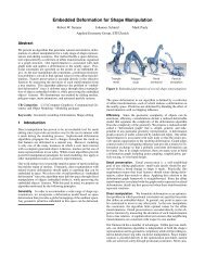
IXABSTRACTThe “blue-c“ project was an internal research project of the Swiss Federal Institute ofTechnology with the goal to build collabor<strong>at</strong>ive, immersive virtual environments whichintegr<strong>at</strong>e the represent<strong>at</strong>ion of real humans as three-dimensional objects. The first of thetwo install<strong>at</strong>ions th<strong>at</strong> were built is a three-sided sp<strong>at</strong>ially immersive back projectionsystem. Sixteen cameras are integr<strong>at</strong>ed in this install<strong>at</strong>ion in order to capture the silhouetteand texture of the user. A 3D-represent<strong>at</strong>ion of the user is gener<strong>at</strong>ed in real time andtransferred to the remote install<strong>at</strong>ion, where it is combined with the virtual world andpresented to the remote user. The remote user is also captured with sixteen cameras andhis 3D-represent<strong>at</strong>ion is transferred back to the first install<strong>at</strong>ion. The interconnectedinstall<strong>at</strong>ions enable multiple users to interact and share applic<strong>at</strong>ions simultaneously. Thepossibility to see the remote user in conjunction with the applic<strong>at</strong>ion gives a high sense ofpresence.This thesis covers the hardware component of the “blue-c“ project, namely the sp<strong>at</strong>iallyimmersive projection system and the image acquisition system. The main challengeassoci<strong>at</strong>ed with the hardware was to combine the projection with the image acquisition.In order to meet this challenge, electrically switchable “phase dispersed liquid crystal(PDLC)“ glass panels are used as projection walls. The panels are switched to transparentfor acquisition and opaque for projection. The switching is repe<strong>at</strong>ed 62.5 times persecond. The cameras, which are loc<strong>at</strong>ed outside of the projection room, can acquire animage of the user through the PDLC glass panels during the transparent st<strong>at</strong>es. The activestereo projection system is only active when the glass panels are opaque.The switchable projection screens are discussed in this dissert<strong>at</strong>ion. The properties ofthe PDLC glass panels are analyzed, including the electrical and the projection properties.The triggering signals, which drive the glass panels, are optimized to minimize theswitching times.An active LCD stereo projection system was developed to enable stereo projection inconjunction with image acquisition. Each projection side includes two LCD projectorsand two ferroelectric shutters. The timings for the left and right eye projection as well asthe blanking of both projectors during image acquisition are selectable.A bright illumin<strong>at</strong>ion with a homogenous light distribution is necessary to facilit<strong>at</strong>e thesilhouette extraction and the texture acquisition. On the other hand, a dark surroundingis advantageous for a good immersion. Therefore an active illumin<strong>at</strong>ion consisting of9,984 LEDs is used, which is switched on and off 62.5 times per second. The illumin<strong>at</strong>ionis only on during image acquisition. Modified shutter glasses are used to keep the lightaway from the user. This is achieved by blocking both shutters of the glasses during imageacquisition.In order to synchronize all active components of the projection and acquisition system,a dedic<strong>at</strong>ed synchroniz<strong>at</strong>ion electronics system was built. A microcontroller is integr<strong>at</strong>edinto the electronics to facilit<strong>at</strong>e quick adapt<strong>at</strong>ion of the triggering timings. Different drivermodules provide the driving signals for the different components.The mechanical construction of the sp<strong>at</strong>ially immersive projection room consists offiber reinforced composites (glass and carbon) and wood. The selected m<strong>at</strong>erials do not
Xinterfere with the electromagnetic tracking system and the design supports the fullfunctionality of the projection and image acquisition system.
XIIUm alle Komponenten zu synchronisieren, wird eine eigens dafür entwickelteSynchronis<strong>at</strong>ionselektronik verwendet. Ein eingebauter Mikrokontroller ermöglicht eineflexible Anpassung der Schaltzeitpunkte der einzelnen aktiven Komponenten.Der mechanische Aufbau des immersiven Projektionsraumes besteht ausFaserverbundwerkstoffen (Glas und Kohlenstoff) sowie aus Holz. Die gewähltenM<strong>at</strong>erialien gewährleisten eine ungestörte Funktion des elektromagnetischenTrackingsystems. Das Design des Aufbaus wurde auf die funktionalen Anforderungen derProjektion und Bildaufnahme hin ausgelegt.
C H A P T E R11INTRODUCTIONThis chapter describes the context and the background of this thesis.1.1 MOTIVATIONAdvancing globaliz<strong>at</strong>ion and the increasing demand for flexibility to react quickly tochanging customer‘s needs are influencing the way in which business is done. Shortresponse and development time are key factors for success. Inform<strong>at</strong>ion andcommunic<strong>at</strong>ion are the primary competitive tools in the 21 st century. The overallincreasing product complexity involves a growing number of people and companies,which are often spread across the whole globe. As a result, the need for traveling andcommunic<strong>at</strong>ion has increased. The internet and e-mail technologies have opened up newmethods of communic<strong>at</strong>ion. Video conferencing has been available for over a decade now.However, even the combin<strong>at</strong>ion of all these technologies cannot always replace face-tofacemeetings.<strong>Computer</strong> power and electronic storage capacity is increasing every year. Threedimensional(3D) CAD d<strong>at</strong>a is widely available in many companies and is used for mostcomplex projects [46]. Some companies already use Virtual Reality (VR) systems forvisualizing CAD d<strong>at</strong>a. The increasing amount of electronic d<strong>at</strong>a available in companies,comprising development and production processes d<strong>at</strong>a, is already improving longdistancecollabor<strong>at</strong>ion. Despite this, communic<strong>at</strong>ion within companies and betweenbusiness partners still has the potential to be improved. The question arises regarding howthe new visualiz<strong>at</strong>ion technologies, computer power and the growing availability of 3Dd<strong>at</strong>a can be used to improve communic<strong>at</strong>ion. Is there a way to use Virtual Reality (VR)for communic<strong>at</strong>ion in day-to-day business?First steps have already been taken to use VR for distributed collabor<strong>at</strong>ion. Computingtools support inform<strong>at</strong>ion exchange and simple communic<strong>at</strong>ion fairly well. However,collabor<strong>at</strong>ion on complex issues is not well-supported by these tools. Successful models ofcomputer supported collabor<strong>at</strong>ive work (CSCW) are still rare [28]. Thus far in virtualmeetings, humans are inadequ<strong>at</strong>ely represented and disembodied through text, voice ortwo-dimensional (2D) video projections. The represent<strong>at</strong>ion of the human is thereforeunn<strong>at</strong>ural. As a result the level of presence of the remote person is low and the separ<strong>at</strong>ion1
2 1 INTRODUCTIONbetween the remote collabor<strong>at</strong>or and the task can be quite frustr<strong>at</strong>ing. Ideally the remoteperson should be embodied by a full size, photorealistic 3D represent<strong>at</strong>ion. Such arepresent<strong>at</strong>ion is ideally visualized with Sp<strong>at</strong>ially Immersive Displays (SID).Particularly in the field of product development the need arises to have acommunic<strong>at</strong>ion tool, which goes beyond the classic video conferencing systems. Theproduct development process consists of many different phases, which involve a largenumber of teams, which are sometimes spread all over the world. The different phasesinclude clarific<strong>at</strong>ion and specific<strong>at</strong>ion of the conceptual formul<strong>at</strong>ion, finding functions,searching for solution principles, classific<strong>at</strong>ion into realizable modules, structuring themodules and layout of the product, to mention just a few of them. <strong>Computer</strong> tools areused to support most of these developmental steps. With increasing product complexities,paralleliz<strong>at</strong>ion of different product development steps has become necessary in order toreduce the development times. Communic<strong>at</strong>ion plays a key role in such a distributedproduct development process. The need arises to have a virtual meeting room, wheredistant development partners can meet ad hoc, without the inconvenience of timeconsumingtraveling. This virtual meeting room should support speech, gesture andmimic in order to allow communic<strong>at</strong>ion <strong>at</strong> a high level of presence. This would enablen<strong>at</strong>ural communic<strong>at</strong>ion, including social communic<strong>at</strong>ion aspects and therefore permit theparticipants to focus, with a high level of efficiency, on the task which needs to be solved.In addition, the virtual meeting room should enable the display of inform<strong>at</strong>ion andproduct d<strong>at</strong>a as needed. The visualiz<strong>at</strong>ion of the product d<strong>at</strong>a and of the remote usersshould be simultaneously and n<strong>at</strong>urally integr<strong>at</strong>ed amongst each other. Existing videoconferencing systems poorly integr<strong>at</strong>e inform<strong>at</strong>ion and product d<strong>at</strong>a with the image of theremote person. In addition, many small but important communic<strong>at</strong>ion details of a face toface meeting, including social aspects, are not supported by most video conferencingsystems.1.2 RELATED WORKSp<strong>at</strong>ially Immersive Displays (SIDs) have become increasingly popular over the pastdecade. They enable the user to work in virtual spaces while being physically surroundedwith a panorama of imagery [25]. The most common SID used today is the CAVEfrom the University of Illinois, Chicago, or one of its variants [6]. This environmenttypically comprises a cubic room with up to six back projection units. Distributed versionsof SIDs allow users to interact with remote collabor<strong>at</strong>ors in telecollabor<strong>at</strong>ion applic<strong>at</strong>ions.These systems usually integr<strong>at</strong>e 2-D video-based human av<strong>at</strong>ars, possibly enhanced withpre-reconstructed geometric models, into the virtual environments [26].A different approach to construct dedic<strong>at</strong>ed SIDs is to integr<strong>at</strong>e the projection unitsand the projection surfaces directly into existing office environments as it has been donein the “Office of the Future“ [15]. For this project, cameras are placed in the ceiling andthe walls of the office to allow telecollabor<strong>at</strong>ion. They use 2D video-based av<strong>at</strong>ars andspeech for interpersonal communic<strong>at</strong>ion.TELEPORT [14] uses special dedic<strong>at</strong>ed visualiz<strong>at</strong>ion rooms for teleconferencing. Theessential idea behind TELEPORT is termed, co-presence: the illusion th<strong>at</strong> remoteconference participants, although actually distant, are present in the local participant‘sphysical space. Each of the interconnected install<strong>at</strong>ions use a stereo projection unit and asingle camera placed on a table in front of the user. The 2D imagery along with the videotexture of the remote participant is then placed in the 3D model of the remote office.
1.3 CONTRIBUTION 3At the MIT Media <strong>Lab</strong> a silhouette-based interactive dual-screen environment namedSIDEshow has been developed [29]. The system extracts a silhouette of the participant todrive an interaction. An IR-camera, <strong>at</strong>tached to the bottom of a screen, captures thesilhouette of the user. The background is illumin<strong>at</strong>ed with infrared light to provide a goodcontrast.In the EU, the Inform<strong>at</strong>ion Societies Technology (IST) project- VIRTUE (VirtualTeam User Environment) focuses on immersive 3D video conferencing systems [52].Each of the install<strong>at</strong>ions integr<strong>at</strong>es a large scale 2D display for visualiz<strong>at</strong>ion. Four camerasare mounted on the edges of each display and a virtual camera view is gener<strong>at</strong>ed from thefour captured images [53]. The color image of the remote user can be observed fromdifferent points of view. However, no stereo projection system or display is used.The Cabin of the University of Tokyo is a five-sided SID, consisting of three wallprojections, a floor and a ceiling projection [12]. In 1997, the Cabin was extended to anetworked environment by connecting it to other SIDs to allow telecollabor<strong>at</strong>ion. Theuser is captured with infrared cameras, placed on tripods inside the SID. Infrared cameraswere chosen because of the low light condition inside the SID. A black and whiterepresent<strong>at</strong>ion of the user is then transferred to the remote install<strong>at</strong>ions.Most SIDs use stereo projection to give the user a high degree of immersion. Togener<strong>at</strong>e the stereo effect, eclipse or polarized technology is used. The Televiewsystem [20] which was cre<strong>at</strong>ed in 1923 was the first commercial applic<strong>at</strong>ion of eclipsetechnology for motion pictures (also known as active stereo projection or field-sequentialstereo projection). However it was not until 1984 th<strong>at</strong> the field-sequential stereoscopicdisplays started to become more popular with the commercializ<strong>at</strong>ion of LC shutter glassesby Stereo<strong>Graphics</strong> [19]. There are many different topics within the area of stereoprojections, which provide the content of many public<strong>at</strong>ions, forexample, [21], [22], [23], [18], [27].Immersive projection systems demand a high resolution. The resolution of a displaywall can be increased by using multiple projectors. For systems with large numbers ofprojectors, an autom<strong>at</strong>ic projection calibr<strong>at</strong>ion is necessary. At the University of Princetona display wall was built in 1998, using eight LCD projectors. Each projector is connectedto a node of a computer cluster and an autom<strong>at</strong>ic projection calibr<strong>at</strong>ion is integr<strong>at</strong>ed [49].In November 2000 the system was scaled up with 24 DLP projectors [50].While stereo projection has already reached a high level of quality, the acquisition ofthe user with simultaneous projection is still very challenging. This often results incompromises between acquisition and projection. Infrared cameras are often used due tothe low light conditions inside SIDs. Sometimes the cameras are placed in front of theprojection, which therefore decreases the immersion quality and the size of the workingarea. In some cases only one camera is used, which only allows for a 2D represent<strong>at</strong>ion ofthe user.1.3 CONTRIBUTIONThe goal was to build a system which enables collabor<strong>at</strong>ion and communic<strong>at</strong>ion amongpeople who are <strong>at</strong> geographically different loc<strong>at</strong>ions with a high level of presence. Thefollowing challenges needed to be met. The person has to be acquired in 3D with fulltextures and colors. At the same time, the person from the remote install<strong>at</strong>ion has to bevisualized in 3D without interfering with the acquisition system. The applic<strong>at</strong>ion, for
4 1 INTRODUCTIONexample a visualiz<strong>at</strong>ion of an assembly line, has to run simultaneously with theconferencing component of the system. The images of the remote person and thevisualiz<strong>at</strong>ion from the applic<strong>at</strong>ion have to be combined and presented on the samevisualiz<strong>at</strong>ion system.In the presented work, the aforementioned issues have been addressed and newsolutions have been developed to build an innov<strong>at</strong>ive prototype of a highly immersiveprojection and video acquisition virtual environment for collabor<strong>at</strong>ive work [41]. Withthe new system it is possible to simultaneously record live video streams of users and toproject virtual reality scenes. This enables a number of participants to interact in a virtualmeeting, represented as completely as possible: fully 3D rendered, supporting motion andspeech in real time [28]. The user, as part of the real world, is therefore synthesized andintegr<strong>at</strong>ed in the virtual world. Thus the SID evolves from a virtual reality system to anaugmented virtuality system.Special solutions had to be found to enable simultaneous projection and pictureacquisition. The cameras are placed behind active projection screens, which can beswitched to a transparent st<strong>at</strong>e for picture acquisition. This solution enables the camerasto be integr<strong>at</strong>ed into a SID without interfering with the projected images. In addition,finding a balance between darkness which is needed for a sharp projection and brightnessfor picture acquisition was addressed. An active LED illumin<strong>at</strong>ion in combin<strong>at</strong>ion withmodified shutter glasses was implemented to allow an acquisition with color cameraswithout disturbing the user.1.4 BLUE-C PROJECT CONTEXTThe presented work was carried out within the context of the blue-c project. In this projecta novel hard- and software system was cre<strong>at</strong>ed th<strong>at</strong> successfully combined the advantagesof a CAVE-like projection environment with simultaneous real-time 3D videocapturing and processing of the user. As a major technical achievement, users can nowbecome part of the visualized scene while keeping visual contact with one another.Consequently, these fe<strong>at</strong>ures make the system a powerful tool for high-end remotecollabor<strong>at</strong>ion and present<strong>at</strong>ion. Thus far, two portals have been implemented withcomplementary characteristics, networked with a gigabit connection. One portal is loc<strong>at</strong>ed<strong>at</strong> the <strong>ETH</strong> main campus, the second <strong>at</strong> <strong>ETH</strong> Hoenggerberg. Various applic<strong>at</strong>ions haveproved the concept and demonstr<strong>at</strong>ed the usefulness of blue-c.
1.4 BLUE-C PROJECT CONTEXT 5Figure 1.1 shows the <strong>ETH</strong> main campus blue-c portal in action. It is a three-sidedCAVE-like portal with actively shuttered projection walls.Figure 1.1 blue-c portal <strong>at</strong> the <strong>ETH</strong> main campusThe second blue-c install<strong>at</strong>ion, loc<strong>at</strong>ed <strong>at</strong> <strong>ETH</strong> Hoenggerberg, is a single projectionwall setup (Figure 1.2). Therefore this install<strong>at</strong>ion requires less demanding solutions forthe simultaneous projection and acquisition then the first install<strong>at</strong>ion. Both systemsacquire the 3D video inlay with 16 cameras and have stereo projection capabilities.Figure 1.2 blue-c portal <strong>at</strong> <strong>ETH</strong> HoengerbergThe blue-c project was organized as an <strong>ETH</strong> internal research project. It started on May1, 2000 and lasted for three years. Four <strong>ETH</strong> research groups particip<strong>at</strong>ed in this project,namely the <strong>Computer</strong> <strong>Graphics</strong> <strong>Lab</strong> (CGL) under the supervision of Prof. Markus Gross,the <strong>Computer</strong> Vision <strong>Lab</strong>or<strong>at</strong>ory (CVL) under the supervision of Prof. Luc Van Gool, the
6 1 INTRODUCTIONCenter of Product Development (ZPE), which is part of the Institute of MechanicalSystems (IMES) under the supervision of Prof. Markus Meier and the chair of <strong>Computer</strong>Aided Architectural Design (CAAD) supervised by Prof. Maia Engeli <strong>at</strong> the beginning ofthe project and l<strong>at</strong>er supervised by Prof. Ludger Hovestadt.The CGL directed the project and was responsible for the core software components,including graphics rendering and 3D video processing, as well as for the computing andnetworking infrastructure. The CVL was responsible for the silhouette extraction on thecaptured images and of the camera calibr<strong>at</strong>ion. The ZPE was responsible for the hardwareand projection setup, including the construction of the first blue-c portal <strong>at</strong> the <strong>ETH</strong> maincampus. The CAAD chair investig<strong>at</strong>ed applic<strong>at</strong>ions and interaction techniques, designedthe virtual reality install<strong>at</strong>ions and built the second blue-c portal <strong>at</strong> <strong>ETH</strong> Hoenggerberg.Figure 1.3 illustr<strong>at</strong>es the framework of the core components of the blue-c project. Inthe following section these core components are briefly described.Applic<strong>at</strong>ionApplic<strong>at</strong>ion Programming Interface3D Video SystemCommunic<strong>at</strong>ionLayerHardwareFigure 1.3 Framework of the blue-c systemHardware. The hardware includes the projection system, the integr<strong>at</strong>ion of theacquisition system, the illumin<strong>at</strong>ion and the synchroniz<strong>at</strong>ion electronics for all thecomponents. The hardware has to s<strong>at</strong>isfy the contradicting needs of projection and imageacquisition. The blue-c hardware is the subject of this thesis.3D Video System. The 3D video software computes a 3D represent<strong>at</strong>ion of the acquiredpersons from inside a blue-c install<strong>at</strong>ion in real-time. The software first builds a 3D pointcloud from multiple camera video streams. The point cloud can then be efficientlyencoded and streamed to a remotely loc<strong>at</strong>ed blue-c portal where it is rendered into theapplic<strong>at</strong>ion. The 3D video system is described in detail in Stephan Würmlin's thesis [1].Communic<strong>at</strong>ion Layer. The acquisition and rendering systems of the distributedinstall<strong>at</strong>ions are connected with each other and thus enable telecollabor<strong>at</strong>ion applic<strong>at</strong>ions.Strict temporal and bandwidth constraints have to be met in order to enable high qualitycollabor<strong>at</strong>ion with live video streams. Furthermore, the system needs to adapt to changingqualities of the network services. The communic<strong>at</strong>ion layer is detailed in EdouardLamboray’s thesis [2].Applic<strong>at</strong>ion Programming Interface. The blue-c Applic<strong>at</strong>ion Programming Interface(blue-c API) exposes the blue-c system functionality to the applic<strong>at</strong>ion developer. Itprovides a rapid applic<strong>at</strong>ion development environment which supports tele-collabor<strong>at</strong>ionand the integr<strong>at</strong>ion of multimedia d<strong>at</strong>a into the virtual world. The blue-c Applic<strong>at</strong>ionProgramming Interface is the subject of Martin Naef’s thesis [3].Applic<strong>at</strong>ion. The applic<strong>at</strong>ions run on top of the blue-c API and are customized to therequirements of the specific hardware and software layout of blue-c in order to make use
1.5 OUTLINE OF THE THESIS 7of the full potential of this new system. Two applic<strong>at</strong>ion areas have been researched in theframework of the blue-c project. Infoticles is a novel inform<strong>at</strong>ion visualiz<strong>at</strong>ion metaphorwhich uses the motion characteristics of particles to explore unexpected d<strong>at</strong>a p<strong>at</strong>terns inlarge, time-varying d<strong>at</strong>asets. This visualiz<strong>at</strong>ion technique is described in detail in the thesisauthored by Andrew Vande Moere [4]. IN:SHOP is the first applic<strong>at</strong>ion to investig<strong>at</strong>e andanalyze the possibilities of integr<strong>at</strong>ing the blue-c technology into buildings. A novelapproach to distributed shopping in a new interactive space is introduced. Physicalshopping floors are connected and extended into virtual and remote spaces. The impactof video stream systems on architecture is described in detail in the thesis written by SilkeLang [5].blue-c is the name for the project, as well as the different install<strong>at</strong>ions, which have beenrealized during this project. In this thesis the project will always be referred to as the “bluecproject“ and the first install<strong>at</strong>ion realized <strong>at</strong> the main campus will be referred to as “bluec“.1.5 OUTLINE OF THE THESISThe thesis is structured as follows:◆ Chapter 2 begins with the requirements list for the blue-c hardware. Based on theserequirements, different implement<strong>at</strong>ion options are presented and evalu<strong>at</strong>ed. Thechosen solutions are then discussed in detail. This chapter sets the basis for thefollowing chapters.◆ Chapter 3 focuses on stereo projection systems. In order to set up an immersiveprojection system it is essential to understand the human visual perception. This isaddressed <strong>at</strong> the beginning of this chapter and is followed by a comparison of differentprojection systems. The most suitable system for blue-c is then discussed in detail.◆ Chapter 4 discusses the active projection screens, which are a core component of theblue-c hardware. The physical, optical and electrical properties are analyzed.◆ Chapter 5 describes the flash illumin<strong>at</strong>ion and the modified shutter glasses.◆ Chapter 6 contains the description of the synchroniz<strong>at</strong>ion electronics. The hardwarecomponents, which are the contents of chapter 3 to 5, are synchronized amongst eachother with these electronics. The graphical user interface to program the differenttimings is also presented in this chapter.◆ Chapter 7 illustr<strong>at</strong>es the mechanical construction of blue-c. The evolution of thearchitectural design as well as the integr<strong>at</strong>ion of the different components is part ofthis chapter.◆ Chapter 8 contains measurements and experimental results of the blue-c hardware.The triggering timings of the different components are discussed. The advantages andthe limits of the implemented system are laid out.◆ Chapter 9 summarizes the conclusions of this thesis and points out further researchdirections.◆ Appendix A shows a selection of design studies of blue-c.◆ Appendix B includes the schem<strong>at</strong>ics of the synchroniz<strong>at</strong>ion electronics.
8 1 INTRODUCTION
C H A P T E R22CONCEPTThe goal of the blue-c project was to build collabor<strong>at</strong>ive, immersive virtual environments,which integr<strong>at</strong>e the represent<strong>at</strong>ion of real humans as three-dimensional objects togetherwith virtual objects into one common virtual workspace. Two install<strong>at</strong>ions areinterconnected to allow bi-directional collabor<strong>at</strong>ion and interaction between peoplesharing virtual spaces. The shape and textures of the participants are captured in real time,in full color and three-dimensionally. Each install<strong>at</strong>ion consists of a projection system andacquisition hardware, both of which oper<strong>at</strong>e in the visual wave length spectrum.Simultaneous projection and picture acquisition are important fe<strong>at</strong>ures of the blue-cproject. The immersive projection has to be combined with high fidelity pictureacquisition. Several different concepts were evalu<strong>at</strong>ed before choosing the implementedsolution.2.1 REQUIREMENTS ON AN IMMERSIVE COLLABORATION SYSTEMEssentially two systems have to be combined into one install<strong>at</strong>ion, an immersivevisualiz<strong>at</strong>ion system and an acquisition system. The image acquisition has to take place inthe visual wave length spectrum and in full color. Multiple cameras are used, which enablea 3D reconstruction of the acquired person. For blue-c it was decided to use sixteencameras because this number is a good compromise between number of view points andcomputing complexity. Simul<strong>at</strong>ions and tests with different camera configur<strong>at</strong>ions, doneby the <strong>Computer</strong> <strong>Graphics</strong> <strong>Lab</strong>, were <strong>at</strong> the origin of this decision. The requirements forthe install<strong>at</strong>ion are listed in Table 2.1.The cameras are loc<strong>at</strong>ed around the working area to give full coverage of the user insidethe install<strong>at</strong>ion. New hardware and software acquisition concepts were developed in theblue-c project therefore it was not possible to define exact camera positions <strong>at</strong> thebeginning of the construction (requirement no. 2). The cameras have to acquire the userfrom a defined distance in order to capture the entire person. This distance depends onthe camera lens which is used. In addition, the person should always be within the focallength of the cameras. Therefore the user should never be too close to the camera(requirement no. 5).9
10 2 CONCEPTTable 2.1 Requirements list for the blue-c install<strong>at</strong>ionNo. Requirement Value, Range, Characteristic Unit1 number of cameras to be installed 16 [pieces]2 positions of cameras in rel<strong>at</strong>ion to theusers3 vertical position of the cameras in rel<strong>at</strong>ionto the user‘s eyes (standing person, 1.7 mhigh)4 number of overhead cameras (verticallyover the user)equally distributed around the user, exactposition not defined, has to be keptvariable+/- 1 [m]1 [piece]5 lens distance to user ≥ 1 [m]6 camera type to be installed color camera7 camera for silhouette acquisition same camera used for texture acquisition8 triggering of cameras all cameras have to be synchronizedamong themselves9 system comp<strong>at</strong>ibility to camera frame r<strong>at</strong>e 30 and lower [1/sec.]10 cameras in front of the projection none11 projection type stereo12 horizontal field of view (FOV) of theprojection13 simultaneous projection and pictureacquisition≥ 180 [°]within one frame l<strong>at</strong>ency14 illumin<strong>at</strong>ion color white15 illumin<strong>at</strong>ion type bright enough for acquisition, notinterfering with projection16 design of install<strong>at</strong>ion represent<strong>at</strong>ive17 flexibility of install<strong>at</strong>ion high (prototype, changing needs expectedafter construction)18 room size for user (L x W) ≥ 2.7 x 2.7 [m]19 maximum size of install<strong>at</strong>ion including allcomponents (L x W x H)20 components to be integr<strong>at</strong>ed in thesystem≤ 10 x 12 x 4.5tracking, cameras, illumin<strong>at</strong>ion,loudspeakers, IR emitters, projectors,screens, synchroniz<strong>at</strong>ion unit[m]21 construction m<strong>at</strong>erial non-magnetic22 interference between components none23 st<strong>at</strong>ic loading capacity of user pl<strong>at</strong>form 1,000 [kg]For the 3D reconstruction of a person, it is important th<strong>at</strong> both silhouette and textureare acquired with the same cameras <strong>at</strong> the same time (requirement no. 7). Any divergencein time or position would increase the complexity of reconstruction. In addition, all the
2.2 PROJECTION SCREEN OPTIONS 11cameras have to be synchronized with each other (requirement no. 8). The blue-c systemshould allow different acquisition frame r<strong>at</strong>es up to a frequency of 30 Hz, which is themaximum camera acquisition frame r<strong>at</strong>e (requirement 9).Immersion is a necessary quality of a highly functional VR system. A high degree ofimmersion means th<strong>at</strong> the user is fully integr<strong>at</strong>ed in the virtual world, in the best case theuser should not be able to distinguish between the real and the virtual world anymore. Thedegree of immersion is influenced by different parameters. One of such parameters is thefield of view (FOV) which describes how much of the viewing area is covered by a displayor a projection screen. In general, a wide FOV improves the feeling of immersion(requirement no. 12). A dark environment around the projection also helps to improvethe degree of immersion. In this case, the real world, including the projection room,becomes less visible. A stereo projection or display gives participants the illusion th<strong>at</strong>objects are coming out of the projection plane, this is a fe<strong>at</strong>ure which also contributes tothe immersion (requirement no. 11).The illumin<strong>at</strong>ion is an important part of the system and has to s<strong>at</strong>isfy differentrequirements. A bright and homogeneous white illumin<strong>at</strong>ion is suitable for acquisitionwhereas dark surroundings are required for an immersive projection (requirement no. 14and 15).Considering all the cameras integr<strong>at</strong>ed in blue-c, a vision-based tracking system wouldbe a logical consequence. However due to the complexity of the project, including all thenew software components, the decision was made to focus on the main goal of the project,the acquisition. Therefore an electromagnetic tracking system was implemented. Thisrequires th<strong>at</strong> the amount of metal in proximity to the tracking system is kept to aminimum (requirement no. 21). This decision does not affect the functionality of blue-cand <strong>at</strong> a l<strong>at</strong>er d<strong>at</strong>e the electromagnetic system can easily be replaced by a vision basedsystem.2.2 PROJECTION SCREEN OPTIONSTo set up an immersive environment projection systems are normally used, which consistof multiple projectors. Head Mounted Displays (HMDs) can also be used with somelimit<strong>at</strong>ions. For the visualiz<strong>at</strong>ion in blue-c it was decided th<strong>at</strong> projection is more suitablethan head mounted displays. The reasons against using HMDs for the blue-c project canbe summarized as follows: A head mounted display covers a large part of the face, therebymaking it unsuitable for conferencing. Shutter glasses are also big but compared to HMDsstill acceptable for conferencing. Most HMDs are heavy and only offer a limited field ofview (FOW). Furthermore, the l<strong>at</strong>ency between detecting a head movement and upd<strong>at</strong>ingthe image to the new head position is still noticeable, which is quite disturbing. Withprojection the visual feedback after a head rot<strong>at</strong>ion is immedi<strong>at</strong>e and other perspectivecorrections to head movements are much less disturbing and toler<strong>at</strong>e more l<strong>at</strong>ency. Dueto these limit<strong>at</strong>ions, simul<strong>at</strong>or sickness and nearsightedness only occur with extensive useof HMDs [25].The question regarding the integr<strong>at</strong>ion of cameras into an immersive projectionenvironment without interfering with the projection arises. Different concepts arepresented in the following sections.
12 2 CONCEPT2.2.1 Lipstick CamerasAn easy setup would be to integr<strong>at</strong>e small lipstick cameras in the projection screen. Thecameras could be mounted in small holes in the screen. For a back projection, this setupis not suitable because the cables from the cameras as well as the cameras themselves causeshadows in the projection. Even with a front projection, the lenses would be visible in theform of black dots. In addition, changing a camera position after install<strong>at</strong>ion would bequite complic<strong>at</strong>ed. Thus, this principle is suitable neither for front nor for back projectionin blue-c.2.2.2 Lipstick Cameras with ShuttersThe proposed setup is based on the lipstick camera principle and is only suitable for frontprojections. The cameras could be placed directly behind a hole in the projection screen.Mechanical shutters close the holes during projection and open them during pictureacquisition (Figure 2.1). Instead of cre<strong>at</strong>ing black holes which would be visible duringprojection, this system only causes small disturbances in the projected image due to thewhite shutters in front of the camera lens. The whole shutter system has to besynchronized with the acquisition system. No investig<strong>at</strong>ions have been made on theamount of vibr<strong>at</strong>ion and noise which would be gener<strong>at</strong>ed by this mechanical system.Figure 2.1 Camera behind a rot<strong>at</strong>ing shutter wheel in combin<strong>at</strong>ion with front projection2.2.3 Semitransparent MirrorA semitransparent mirror in front of the projection screen, as shown in Figure 2.2, wouldallow images to be acquired in the same way th<strong>at</strong> a virtual camera would function behindthe screen. As many cameras as desired could be integr<strong>at</strong>ed without disturbing theprojection. Due to the distant position of the cameras, full coverage of a person inside thesystem would be assured. A disadvantage of this method is the loss of light from theprojected image as well as from the acquired image. Furthermore, the construction is verylarge and the semitransparent mirror would have to have <strong>at</strong> least the size of the screen. Ifthe mirror is mounted <strong>at</strong> an angle of 45° to the projection screen, its size would be 1.4times th<strong>at</strong> of the screen. A semitransparent mirror such as this one would be fragile and
2.2 PROJECTION SCREEN OPTIONS 13very expensive. The upper region of the room would have to be completely dark, otherwisedisturbing reflections would interfere with the projection.Figure 2.2 Semitransparent mirror in front of the projection screen2.2.4 Immersive Front ProjectionThis approach is based on the fact th<strong>at</strong> the field of view (FOV) is important for the degreeof immersion. A back projection and a front projection could be set up in such a way th<strong>at</strong>,from a defined position of the user‘s head, they will cover exactly the same FOV. In thiscase, the size of the screen would have to increase linearly with the distance of the observerto the screen. Therefore, a 2.1 m high and 2.8 m wide screen (projection r<strong>at</strong>io 3:4) <strong>at</strong> adistance of 1.5 m from the observer produces the same immersion th<strong>at</strong> a 6.3 m high and8.4 m wide screen would produce <strong>at</strong> a distance of 4.5 m. The observed brightness, on theother hand, decreases with increasing distance to the screen. The vertical viewing angle αis in both cases 65° for a person with a 1.6 m eye height. A bigger screen <strong>at</strong> a longerdistance has the advantage th<strong>at</strong> the integr<strong>at</strong>ed cameras are much less disturbing for the usersince their rel<strong>at</strong>ive size is smaller compared to the screen size. Furthermore, if the user stayswithin the same confined area as he would with the smaller projection system, the userwould always be within the full coverage range of the cameras.Figure 2.3 shows a three-sided back projection (upper two images) and a three-sidedfront projection (lower two images). The vertical viewing angle α as well as the viewinginclin<strong>at</strong>ion angle is the same for both projections, as seen in the two images on the left.
14 2 CONCEPTOn the top view of the front projection (lower right image) the working area, marked withdotted lines, is the same as for the back projection.Figure 2.3 Side and top view of a back projection (up) and a front projection (down)Given th<strong>at</strong> the height of the install<strong>at</strong>ion room is 4.5 m, the maximal screen size couldbe 4.5 m x 6 m. Under the assumption th<strong>at</strong> the vertical viewing angle α is 65°, the distancebetween the user and the screen would be 3.21 m. The user would have to stand on apl<strong>at</strong>form, 1.8 m above the ground to have the same viewing inclin<strong>at</strong>ion angle as he wouldhave with the smaller screen. In a given working area of 3 m x 3 m it would be very difficultto setup a projection where the user or the base do not interfere with the projection beam.Furthermore, <strong>at</strong> a distance of 3.21 m from the screen, the camera lenses would still be verynoticeable.2.2.5 Polarized Stripes Projection ScreenThe polarized stripes approach proposes the use of altern<strong>at</strong>ing polarizing structures in theprojection screen for projection and acquisition. In Figure 2.4 for instance, horizontalstripes are used to divide the projection screen into projection and acquisition surfaces.The projection surfaces are co<strong>at</strong>ed with projection m<strong>at</strong>erial (projection stripes). Theacquisition surfaces are transparent stripes covered with a polarizer. Polarized light is usedfor the projection. The polariz<strong>at</strong>ion orient<strong>at</strong>ion of the projected light is orthogonal to thepolariz<strong>at</strong>ion of the acquisition strips on the projection screen. The projection beam,therefore, does not pass through the acquisition stripes and only projects an image on theprojection stripes. On the other hand, the cameras can look through the acquisition stripes<strong>at</strong> the user since the user is illumin<strong>at</strong>ed with non-polarized light. The cameras can beplaced anywhere behind the projection screen out of the projection beam therebyproducing good coverage of the user, which allows a large range of focus. A disadvantageto this approach is th<strong>at</strong> only 50% of the range of projection, in terms of resolution andbrightness, is used. Additional loss in brightness may occur, depending on the type of
2.2 PROJECTION SCREEN OPTIONS 15projectors used and on how the polariz<strong>at</strong>ion on the projector side is implemented. Thesame limit<strong>at</strong>ions also apply for the acquisition.Figure 2.4 Polarized stripe projection screenAnother way to combine opacity and translucency in one screen is to use a m<strong>at</strong>erial,which has two preferred light p<strong>at</strong>hs. A holographic layer in a glass panel could be used forthis property, as it has been done in some commercially available products. Light comingfrom a defined angle (e.g. 36°) is redirected and forwarded perpendicularly on the otherside of the screen, while light coming from other directions is not altered. Thus it ispossible to simultaneously make a projection and to look through the holographicprojection screen with the camera.2.2.6 Shuttered Projection ScreenAs in the approach of the “polarized stripe projection screen“ the cameras could bemounted anywhere behind the projection screen, out of the projection beam. A specialprojection screen has to be used, which can be switched from opaque to transparent andback. The idea is to use time multiplexing to combine the projection and acquisition [44].During the opaque st<strong>at</strong>e of the projection screen, the projection is running and an imageis projected onto the screen. During the transparent st<strong>at</strong>e, the cameras can take images ofthe user inside the install<strong>at</strong>ion. The switchable projection screen has to be synchronizedwith the acquisition system. By switching between the transparent and opaque st<strong>at</strong>esquickly enough, no flickering will be observable and the cameras will not be visible to theuser.Switchable glass panels are commercially available and can be used as shutteredprojection screens. They are based on phase dispersed liquid crystal (PDLC) technologyand can be electrically switched from transparent to opaque. The maximum width of thepanels which is available is 950 mm. For a projection room up to 2.85 m x 2.85 m threeof these panels would have to be integr<strong>at</strong>ed per side. The gaps between the panels wouldbe visible. The glass panel itself can cause reflections th<strong>at</strong> are comparable to normal glasspanels. Therefore, careful design of the install<strong>at</strong>ion and illumin<strong>at</strong>ion is important.
16 2 CONCEPT2.3 EVALUATION OF THE DIFFERENT OPTIONS AND DECISIONThe different concepts presented in the previous section were evalu<strong>at</strong>ed in order to decidewhich concept to use for blue-c. The front projection concept was not taken intoconsider<strong>at</strong>ion, since it is not suitable for the given room size as discussed insubchapter 2.2.4.Since brightness and sharpness of the images, projected on the holographic screen,highly depend on the viewing angle, this m<strong>at</strong>erial is also not suitable for SID systems andthus it was not taken into further account.Table 2.2 Evalu<strong>at</strong>ionCriteriaWeighting (w)Lipstickcamerasvalue (v)v*wLipstickcameraswith shuttervalue (v)v*wSemitransparentmirrorvalue (v)v*wPolarizedstripesvalue (v)v*wShutteredprojectionscreenvalue (v)v*wprojection 0.3hot spot behavior 0.06 4 0.24 4 0.24 4 0.24 2 0.12 2 0.12diffusion property 0.06 4 0.24 4 0.24 3 0.18 3 0.18 3 0.18reflection property 0.06 4 0.24 4 0.24 1 0.06 2 0.12 1 0.06disturbances (points, lines) 0.06 1 0.06 2 0.12 3 0.18 1 0.06 2 0.12shadows and interferences 0.06 1 0.06 1 0.06 3 0.18 4 0.24 4 0.24acquisition 0.4distance of camera to object 0.04 1 0.04 1 0.04 4 0.16 4 0.16 4 0.16coverage by cameras 0.08 1 0.08 1 0.08 4 0.32 4 0.32 4 0.32acquired image quality 0.12 3 0.36 3 0.36 2 0.24 1 0.12 1 0.12flexibility of camerapositions0.16 1 0.16 1 0.16 3 0.48 4 0.64 4 0.64construction 0.3construction complexity 0.06 4 0.24 3 0.18 2 0.12 1 0.06 3 0.18technical feasibility 0.06 4 0.24 2 0.12 1 0.06 1 0.06 2 0.12implement<strong>at</strong>ion time 0.09 4 0.36 3 0.27 2 0.18 1 0.09 2 0.18costs 0.09 4 0.36 3 0.27 1 0.09 2 0.18 3 0.27TOTAL 2.68 2.38 2.49 2.35 2.71
2.4 THE THREE PHASES 17Different criteria concerning the projection, acquisition and construction were used forthe evalu<strong>at</strong>ion of the remaining concepts. Each solution was r<strong>at</strong>ed with a value between 1(poor) and 4 (very good) for each of the criteria.The active projection screen offers the best compromise between projection, pictureacquisition and construction. The projection quality is good, as it is only disturbed byvertical stripes between the different glass panels. In regards to the acquisition, the mainadvantage is the placement of the cameras. They can be placed anywhere behind thescreens, as long as they do not interfere with the projection beam. Therefore, they cancover the whole person independently of the person‘s position in blue-c. The concept withthe switchable glass also offers a good level of flexibility which was necessary for anexperimental setup when the project was first initi<strong>at</strong>ed, since the camera position can bechanged as often as needed. This, of course, would not be possible if the cameras wouldbe mounted behind holes in the projection screens. Preliminary tests showed th<strong>at</strong> theshuttered projection screens can be switched <strong>at</strong> frequencies of 60 Hz with an acceptabledelay in response time.2.4 THE THREE PHASESWith the use of actively shuttered projection screens, the projection and acquisition haveto take place <strong>at</strong> different moments. This time multiplexing between projection andacquisition has two or three different phases, depending on the projection. For a normalprojection two time phases are necessary, one for projection and one for acquisition. Incombin<strong>at</strong>ion with an active stereo projection the number of phases are three; one for theleft eye projection, one for the right eye projection and one for the image acquisition [48].This sequence has to be repe<strong>at</strong>ed with a frequency, which is high enough to avoidnoticeable flickering.Figure 2.5 The three phasesAn important question arose regarding the method for illumin<strong>at</strong>ing the user withoutdisturbing the user and without altering the projection quality and thus the degree ofimmersion. The illumin<strong>at</strong>ion has to be in the visible light spectrum since color camerasare used. The idea is to make use of the three phases and to have a flash illumin<strong>at</strong>ion whichis only activ<strong>at</strong>ed during picture acquisition. To protect the user from the light shutterglasses are worn, which are synchronized with the illumin<strong>at</strong>ion [45], [47]. These shutterglasses are also needed for the active stereoscopic projection. Figure 2.5 illustr<strong>at</strong>es such a
18 2 CONCEPTprojection sequence, which is followed by an acquisition sequence. The frequency of theflash illumin<strong>at</strong>ion as well as of all other visible devices has to be kept high enough (e.g.62.5 Hz) so as not to disturb the user with annoying flickering.The components which needed to be synchronized are listed on the left side ofFigure 2.6. The projectors have to be turned off during acquisition to avoid projectingdirectly onto the user, as well as causing reflections on the active projection screens duringacquisition. For this reason, additional shutters are mounted in front of the projectors,which remain closed during acquisition. These shutters can also be used to gener<strong>at</strong>e astereo projection as described in chapter 3.Figure 2.6 Timing of the three phases2.5 SETUPThe active projection screens allow the cameras to be arranged around the projectionroom. The layout of blue-c is a three-sided projection room with a quadr<strong>at</strong>ic ground view(Figure 2.7). This quadr<strong>at</strong>ic layout, as it has been used for the first time in theCAVE [6], allows standard projection hardware to be used. Edge blending is notrequired because the different projections are on different screens.Figure 2.7 blue-c layout
2.5 SETUP 19Figure 2.8 shows an overview of all components of blue-c, including the connectionscheme. Two projectors in combin<strong>at</strong>ion with two shutters are used per side to gener<strong>at</strong>e astereoscopic projection [40]. The six projectors of the three-sided projection room areconnected to a SGI Onyx 3200. The control room of blue-c is equipped with four SGImonitors, which share the graphic pipes with four of the six projectors. When anapplic<strong>at</strong>ion is running in blue-c, the oper<strong>at</strong>or can see both channels of the blue-c's middleprojection screen as well as the two left eye channels of the left and right screens. When anapplic<strong>at</strong>ion is not running in blue-c, the monitors can be used <strong>at</strong> full resolution of 1920 x1080. Four two-way splitters are connected to the corresponding outputs of the SGI. Thesplitters have a bandwidth of 500 MHz (3dB bandwidth). The signal going to theprojectors is a XGA (1024 x 768) 60 Hz signal [40]. The projection system is discussed indetail in Chapter 3.The sixteen cameras of blue-c are connected with fire-wire cables to a Linux cluster.The Linux cluster consists of seventeen nodes. Each of the cameras is connected to a singleprocessornode which preprocesses the incoming images. The sixteen nodes are connectedover a proprietary 100 Mbit Ethernet link to a dual-processor node. The preprocessedimages are transferred to this dual-processor machine, which gener<strong>at</strong>es a 3D model of theacquired person.A total of nine PDLC glass panels are used for the three active projection screens. Theyare switched to transparent in order for the cameras to acquire an image and to opaque forthe projection. The active projection screens are the subject of Chapter 4.A flash illumin<strong>at</strong>ion consisting of LEDs is used to illumin<strong>at</strong>e the inside of blue-c toallow the cameras to take decent images. This illumin<strong>at</strong>ion is switched on during imageacquisition and switched off for projection. The user wears modified shutter glasses, whichallow him to see the stereo projection and which protect the user‘s eyes from theillumin<strong>at</strong>ion caused by the flash. Chapter 5 explains the details of the flash illumin<strong>at</strong>ionand the modified shutter glasses.Figure 2.8 Components overviewThe PDLC glass panels, the shutters in front of the projectors, the flash illumin<strong>at</strong>ion,the cameras as well as the IR-emitter for the shutter glasses are synchronized by custommadesynchroniz<strong>at</strong>ion electronics. As seen from Figure 2.8, there is no electrical
20 2 CONCEPTconnection between the SGI Onyx (together with the projectors) and the rest of thecomponents. This allows the image acquisition to run independently from the renderingsystem, thereby achieving more flexibility. The synchroniz<strong>at</strong>ion electronics are discussedin detail in Chapter 6. The exact trigger timings are explained in Chapter 8.
C H A P T E R33STEREO PROJECTIONSince the beginning of photography, people have tried to capture the third dimension withthe help of stereoscopy. Two different images, corresponding to the view of each eye, werecaptured and presented to the viewer with a special binocular mechanism. Today, with theadvances in computer graphics, the stereoscopic visualiz<strong>at</strong>ion of computer d<strong>at</strong>a has givena considerable boost to stereo projection and display systems. Most of the systems useprojections in combin<strong>at</strong>ion with special eyewear to gener<strong>at</strong>e the 3D images. Also someapproaches were made to enable glasses-free stereo experiences with auto stereoscopicdisplays and projections. One approach is to write the right image into the even numberedcolumns of a fl<strong>at</strong> panel display (FPD) and the left image into the odd numbered columns,respectively. The left and the right images are correctly presented to the right and the lefteye, using a prism mask in front of the FPD [9]. A head tracking mechanism is necessaryfor detecting the position of the user‘s head and moving the mask accordingly. This kindof display can reproduce a realistically accur<strong>at</strong>e stereo projection only if the user‘s head iswithin a defined distance range from the display. Altern<strong>at</strong>ively to the prism mask alenticular mask can be used [9]. This technology, consisting of a moving mask in front ofthe screen, is only applicable for medium and small displays. A projection in combin<strong>at</strong>ionwith a directional reflection screen is an altern<strong>at</strong>ive to the small displays. Two projectorsare positioned in such a way, th<strong>at</strong> the two projections are directly reflected into thecorresponding user‘s eye [11]. This method only works for one single head position. Theviewing area can be enlarged by using more projectors. With an increasing number ofprojectors, the computer power also has to be increased. The glass-free multi-viewerstereoscopic viewing experience is, therefore, expensive because of added comput<strong>at</strong>ionalpower and a large number of projectors.Stereo projections where the user has to wear special eyewear, are the most commonmethod. These stereoscopic systems can be scaled and combined to multi-projectionsystems without any problems and are based on commonly used projection hardware. Theimage for the left and the right eye are projected on the same screen and are then separ<strong>at</strong>edby the eyewear to give the correct image to each eye. This works independent of theviewer‘s position in rel<strong>at</strong>ion to the projection screen. Stereo projection systems usingspecial eyewear will be discussed in detail in section 3.2.21
22 3 STEREO PROJECTION3.1 HUMAN ANATOMYThe eye is one of the most important sensory organs for the perception of theenvironment. It can acquire an incredible amount of inform<strong>at</strong>ion. Only in situ<strong>at</strong>ionswhen the visual system reaches its limits, do the other sensory organs start to play adominant role. The same applies for virtual reality (VR), where most inform<strong>at</strong>ion istransmitted visually. Therefore, in order to set up an immersive projection system, it isimportant to understand how the human visual perception functions. Of particularinterest is depth perception, from which the distance of the eye to an object can bedetermined.3.1.1 Viewing AngleThe viewing angle is determined by the physical construction of the eye and by its positionin the face. When the eye is directed forward and kept st<strong>at</strong>ionary, the viewing angle of ahealthy eye is limited by the nose, the brow as well as other parts of the face. The fourviewing angles as measured by W. Charman [16] are listed in Table 3.1. The angles havebeen measured in rel<strong>at</strong>ion to the visual axes with the eyes directed forward.Table 3.1 Viewing anglesNasal Temporal Superior Inferior60° 100° 60° 70°With a straight ahead view, the combined horizontal viewing angle of the two eyes is±100°, with an overlapping coverage of 120°. Despite the large viewing field, the humaneye only has sharp vision in a rel<strong>at</strong>ively narrow area. The eye has, therefore, to be directedtowards the detail of interest. Theoretically, the eye can scan a field extending ±45°. Inpractice, only about ±20° are used and bigger movements are assisted by headrot<strong>at</strong>ion [51].When building an immersive VR system, the large field of view of the human visualsystem has to be taken into consider<strong>at</strong>ion. Projection systems with multiple surroundingscreens, which cover a large field of view and also allow head movements are thereforedesirable.3.1.2 Temporal ResolutionThe human eye is most sensitive to flickering <strong>at</strong> its periphery. Flickering frequenciesaround 20 Hz are the most disturbing. For frequencies above 60 Hz, no disturbances arereported and the eye adapts to the average brightness [16].A frequency of 20 Hz is the limit concerning the temporal resolution of single images.Above this frequency the human eye can no longer distinguish between different images.Nevertheless flickering may still be visible. Some TV sets and most professional movieprojection systems take advantage of this fact by projecting each image twice. Thiselimin<strong>at</strong>es flickering while still maintaining the original frame r<strong>at</strong>e.The pupil itself is slower compared to the temporal resolution and can respond tochanges in light level <strong>at</strong> frequencies up to about 4 Hz [16].For a VR system it is therefore important th<strong>at</strong> all visible components are triggered withfrequencies above the flickering frequency. This also applies to the components which areonly peripherally and weakly visible. In blue-c the visible triggered components are the
3.1 HUMAN ANATOMY 23shutter glasses, the stereo projection, the active illumin<strong>at</strong>ion and the active projectionscreens.3.1.3 Depth PerceptionMany different factors contribute to depth perception. Some perceptions of depth can beexperienced with one eye while others rely on binocular vision. The experiences which thehuman has had will also play an important role in depth perception. For example, it ismuch easier to estim<strong>at</strong>e the distance of a known object than of an unknown object. In thefollowing section an overview of relevant factors for depth perception is given [23], [17].Motion Parallax. When in motion, closer objects “move“ more than distant ones.Occlusion. Distant objects are partially obscured by closer ones.Perspective. The classic railway tracks, which appear to get closer together when they arefurther away.Binocular disparity. Each eye sees a slightly different view of the world and the braincan determine distance based on the differences.Accommod<strong>at</strong>ion. The distance <strong>at</strong> which the eye is focused.Convergence. The eyes rot<strong>at</strong>e around the body‘s vertical axis to point the eyes <strong>at</strong> closeobjects.A normal mono projection can make use of parallax, occlusion and perspective. Inaddition, a stereo projection uses the binocular disparity and convergence. Figure 3.1illustr<strong>at</strong>es the principle of a stereo projection. The left and the right eye see two differentimages of a tree, thereby giving the illusion th<strong>at</strong> the tree is loc<strong>at</strong>ed in front of the projectionscreen. The technical realiz<strong>at</strong>ion is discussed in section 3.2.Figure 3.1 Stereo projectionUnfortun<strong>at</strong>ely there is no projection technique which can appropri<strong>at</strong>ely stimul<strong>at</strong>eaccommod<strong>at</strong>ion. With a mono or stereo projection, accommod<strong>at</strong>ion always has to bedone to the screen surface. Furthermore in the real world, objects <strong>at</strong> depths th<strong>at</strong> differ fromth<strong>at</strong> of the fix<strong>at</strong>ed target are blurred, whereas in a virtual environment they are(unn<strong>at</strong>urally) in focus. This decoupling between convergence and accommod<strong>at</strong>ion may bea cause of eyestrain. A remedy to this problem is to slightly blur the projected image. Witha non-stereoscopic display a higher resolution is preferred since it produces a betterstimulus for accommod<strong>at</strong>ion. With stereoscopic displays, improvements in resolutionsincrease the conflict between accommod<strong>at</strong>ion and the convergence system [24].
24 3 STEREO PROJECTION3.2 STEREO PROJECTION SYSTEMSStereo projection makes use of the ability of humans to estim<strong>at</strong>e the distance of an objectby binocular disparity and convergence. Therefore, two different images have to bepresented to the person‘s left and right eye. In order to do so, different types ofmultiplexing are used. The projection system consists of a multiplexing system in the formof one or two projectors and a de-multiplexing system, normally in the form of glassesworn by the user. It is important th<strong>at</strong> the transmission medium, such as the projectionscreen, maintains the multiplex coding.3.2.1 Comparison and DiscussionA stereo projection system can be qualified by different criteria. One of them is the lightloss of the stereo projection system compared to an equivalent normal projection system.Another very important factor for a projected image is the so-called contrast r<strong>at</strong>io, whichcompares the "wanted" amount of light coming from the projection with the "unwanted"ambient light. This r<strong>at</strong>io should be as high as possible in order to reach a good level ofprojection quality. If the projection screen is additionally illumin<strong>at</strong>ed with ambient light,the projected image fades or becomes completely invisible. Thus it is important to alsoknow the <strong>at</strong>tenu<strong>at</strong>ion of the system for ambient light.In the following section, the most common stereo projection systems are presented.The percentages are calcul<strong>at</strong>ed in rel<strong>at</strong>ion to the total light output of the projection systemand indic<strong>at</strong>e the total light perceived by one eye.Active stereo projection. Active stereo projection uses time multiplexing to encode thetwo views [23]. The images for the left and the right eyes are projected sequentially withthe same projector. Shutter glasses, which are synchronized with the projection system,assure th<strong>at</strong> the images for the left and the right eye are separ<strong>at</strong>ed correctly [20]. Only CRTand DLP projectors are fast enough to switch between the two images for the left and righteye.As the left and right eye images are sequentially projected with one projector, the dutycycle per eye is 50%. However, an extra blanking of about 10% between the left and rightimage is required to ensure appropri<strong>at</strong>e separ<strong>at</strong>ion of the two stereo channels. Since bothchannels are projected with the same projector, the light loss in the projector itself onlyconsists of the 10% blanking time. Then the unpolarized light has to pass through theshutter glasses, which separ<strong>at</strong>es the two channels. The separ<strong>at</strong>ion process itself blocks 50%of the projection and only lets the images for the corresponding eye pass through. The LCshutters,with their polarizers, cause an additional loss of approxim<strong>at</strong>ely 65% [19].Therefore, the total efficiency of an active stereo projection system per eye isI = 90% ⋅ 50% ⋅ 35% = 16%(3.1)Figure 3.2 Active stereo projection (single CRT or DLP projector)The ambient light reflected or passing through the projection screen is unpolarized.When the light passes through the shutter glasses about 50% is lost corresponding to the
3.2 STEREO PROJECTION SYSTEMS 25black period of each eye‘s shutter glass panel. From the remaining light, another 65% islost as it passes through the polarizers of the shutter glasses. Therefore, only about 17.5%of the ambient light reaches the user. The contrast r<strong>at</strong>io is16%C = --------------- = 0.91 . (3.2)17.5%LCD passive stereo projection. Passive stereo projection consists of two projectors perscreen. One projects the images for the left eye while the other simultaneously projects theimages for the right eye. The two projectors are equipped with external polarizers, inwhich the axis is oriented orthogonally between each one. The user has to wear polarizedglasses with the polariz<strong>at</strong>ion axes oriented accordingly to the axes of the polarizers, whichare loc<strong>at</strong>ed in front of the projectors. The polarized glasses are worn in order to separ<strong>at</strong>ethe two projection channels. The projection screen which is used has to maintain thepolariz<strong>at</strong>ion.LCD projectors emit polarized light, which in the case of a three chip projector, isnormally aligned in two different axes. This light can be aligned to a single polariz<strong>at</strong>ionaxis by placing an external polarizer in front of the projector lens. To avoid color distortionit is important th<strong>at</strong> the polariz<strong>at</strong>ion axes of the external polarizer is exactly aligned withthe bisecting line between the two original polariz<strong>at</strong>ion axes. Fortun<strong>at</strong>ely in most LCDprojectors the two polariz<strong>at</strong>ion axes are more or less orthogonal to each other, therebyallowing an orthogonal orient<strong>at</strong>ion of the two external filters while keeping the same lightthroughput.The cumul<strong>at</strong>ed light of the two projectors is set as the 100% reference for the followingevalu<strong>at</strong>ion. The light of the projection passing through the external polarizers is <strong>at</strong>tenu<strong>at</strong>edby 30% [34]. After passing through the projection screen, this polarized light has to thenpass through the polarized glasses. For each eye, one of the two projectors is almostcompletely blocked since the polariz<strong>at</strong>ion axes are orthogonal, which results in a 50% lossof light. The light produced by the projector which passes through has the samepolariz<strong>at</strong>ion axes as the polarized filter in the glasses, which therefore only looses about16% of intensity due to imperfections in the filters [22]. In summary, from the total lightof the projectors onlyreaches each of the eyes.I = 70% ⋅ 50% ⋅ 84% = 29%(3.3)Figure 3.3 Passive stereo projection (two LCD projectors)About 42% of the unpolarized ambient light passes through the polarized glasses. Thecontrast r<strong>at</strong>io is therefore29%C = ---------- = 0.69 . (3.4)42%CRT and DLP passive stereo projection. This stereo projection method is basicallythe same as the LCD passive stereo projection. The primary difference is th<strong>at</strong> the CRT
26 3 STEREO PROJECTIONand DLP projectors project unpolarized light. In this case, the loss caused by the polarizer<strong>at</strong> the output of the projector is approxim<strong>at</strong>ely 55%. Therefore, the total efficiency of thetwo projectors system per eye isI = 45% ⋅ 50% ⋅ 84% = 19% . (3.5)Figure 3.4 Passive stereo projection (two CRT or DLP projectors)Again about 42% of the ambient light passes through the polarized glasses. Thecontrast r<strong>at</strong>io in this case is19%C = ---------- = 0.45 . (3.6)42%Active LCD stereo projection. Active LCD stereo projection systems are notcommercially available. The proposed system has been developed <strong>at</strong> the ZPE institute forthe blue-c project. Similar to the LCD passive stereo projection, two projectors are usedto gener<strong>at</strong>e a stereo projection. One of them is always projecting the image for the left eyewhile the other is projecting the image for the right eye. External LC shutters in front ofthe projectors altern<strong>at</strong>ely open and close the projector beams. Thereby gener<strong>at</strong>ing an activestereo projection, which can be seen with the help of shutter glasses. Since most LCDprojectors project almost continuously without interruption between image upd<strong>at</strong>es [37],there is no need to synchronize the external shutters with the refresh r<strong>at</strong>e of the projector.This fe<strong>at</strong>ure allows complete freedom when choosing the stereo frequency and projectiondur<strong>at</strong>ion per eye.To determine the light loss of this system, it is assumed th<strong>at</strong> both projectors areprojecting continuously and th<strong>at</strong> the external shutter allows each image to be projectedwith a 45% duty cycle. This already includes an extra blanking between the left and rightimages to guarantee a good separ<strong>at</strong>ion of the two stereo channels. The light coming out ofthe LCD projectors is already polarized. This light has to pass through the LC shutterswhich consist of two glass panels with linear polarizers and liquid crystals in between. TheLC shutters have to be oriented according to their first polarizers so th<strong>at</strong> all three colors ofthe projectors pass through equally. The light loss caused by the LC shutter in thetransparent st<strong>at</strong>e is about 50%. The light of both projectors reaches the projection wall,where it is depolarized by the used PDLC glass panels. After the projection wall, the lighthas to pass through the shutter glasses. Each of the two shutters in the glasses block oneprojection completely and let the other pass through with an efficiency of about 35%.Therefore, the total efficiency of this system isI = 45% ⋅ 50% ⋅ 50% ⋅ 35% = 4%(3.7)
3.2 STEREO PROJECTION SYSTEMS 27Figure 3.5 Active stereo projection with external LC shutters (two LCD projectors)About 50% of the ambient light is lost during the black period of each eye‘s shutterglass panel. From the remaining light, another 65% is lost when passing through theshutter glasses in the transparent st<strong>at</strong>e. Therefore, 17.5% of the ambient light reaches theuser. The contrast r<strong>at</strong>io in this case is4C = --------- = 0.23 . (3.8)17.5As exemplified by the comparison of the different stereo projection systems, the passivestereo projection has the highest level of efficiency. On the other hand, the contrast r<strong>at</strong>iois best when using a DLP or CRT active stereo projection. The comparison does not takeinto account the different light outputs of the projectors themselves and the human lightperception, which is logarithmic.Passive stereo projection systems offer a high light output for a competitive price.Inexpensive polarized eyewear can be used to experience the stereo projection. Thedrawback is th<strong>at</strong> passive systems need special projection screens, which maintainpolariz<strong>at</strong>ion. Furthermore, the systems are susceptible to head inclin<strong>at</strong>ion since thepolarizers of the stereo glasses have to be aligned with the polarizers in front of theprojectors.Active stereo projection systems offer a good channel separ<strong>at</strong>ion between the twoprojected images. The LCD active projection systems have a higher light loss compared toother active systems however they are also less expensive. In the year 2000, when theprojection system for blue-c was selected, active DLP projectors were just emerging andthey were five to ten times more expensive than the proposed active LCD system. On theother hand, the active CRT projectors th<strong>at</strong> are normally used have a lower light outputcompared to LCD and DLP projectors. Moreover, they are double the cost of an activeLCD stereo projection system. In regards to these aspects, the active stereo projectionsystem was a valid altern<strong>at</strong>ive to the other active projection systems. Furthermore, theexternal shutters offered considerable advantages for the blue-c project, as discussed in thenext section.3.2.2 Decisionblue-c is a three-sided immersive projection room. The projection has to work incombin<strong>at</strong>ion with the image acquisition system and has to be comp<strong>at</strong>ible with the PDLCglass panels. The requirements for the blue-c projection system are:◆ Comp<strong>at</strong>ibility with PDLC projection screens (PDLC do not retain polariz<strong>at</strong>ion)◆ Blanking with adjustable dur<strong>at</strong>ion and frequency for image acquisition.◆ Projection intensity suited for a three-sided projection room.
28 3 STEREO PROJECTIONUnder these conditions the LCD active stereo projection system is the most suitablesystem for blue-c. The reasons can be summarized as follows:◆ Only active stereo projection systems are comp<strong>at</strong>ible with the PDLC glass panels,which are used as projection screens in blue-c, because PDLC panels do not keep thepolariz<strong>at</strong>ion.◆ The external shutters give a high level of flexibility concerning the timings for thestereo projection, including the blanking required during image acquisition.◆ No synchroniz<strong>at</strong>ion is needed between the projectors and the shutters.◆ The system has enough light output for a multisided immersive projection room. Toomuch projection light would light up the adjacent projection screens and thus reducethe contrast.◆ The price is lower than comparable active stereo CRT or DLP solutions.The technical realiz<strong>at</strong>ion of the active LCD stereo projection system is discussed in thenext section.3.3 ACTIVE LCD STEREO PROJECTIONActive LCD stereo projection systems are not commercially available. The system has beendeveloped especially for blue-c because it offers some important advantages incombin<strong>at</strong>ion with the simultaneous image acquisition of the blue-c project.Figure 3.6 Active LCD stereo projection systemThe active LCD stereo projection system of blue-c uses two Sanyo XF12 three chipLCD projectors per side. They have a XGA (3x1024x768 pixels) resolution and 3500ANSI lumen output. The projectors are equipped with a 1.2:1 lens for a short projectiondistance. Each system consists of a separ<strong>at</strong>e rack, where two projectors are mounted oneupon the other. The alignment of the projectors can be adjusted to provide a congruentprojection. Ferroelectric (FE) liquid crystal shutters with a size of 140 mm x 140 mm are
3.3 ACTIVE LCD STEREO PROJECTION 29mounted in front of each projector. The cost of the active LCD stereo projection system,consisting of two projectors, two shutters and one rack, is approxim<strong>at</strong>ely € 33,000.-.Figure 3.6 shows one of the three projection systems installed in blue-c. The shutters infront of the projectors are rot<strong>at</strong>ed in order to be correctly aligned between the polarizedlight from the projectors and the polarizers of the shutter.3.3.1 Ferroelectric ShuttersThe shutters in front of the projectors have to be switched on and off with a frequency ofapproxim<strong>at</strong>ely 60 Hz.Twisted Nem<strong>at</strong>ic (TN) liquid crystal shutters, as used in shutter glasses, can have acontrast r<strong>at</strong>io of 1000:1 or better [35]. They switch in about 2.5 ms from black totransparent and reversely they switch from transparent to black in less than 1ms [19], [18] [36]. Ferroelectric (FE) liquid crystal shutters have approxim<strong>at</strong>ely the samecontrast r<strong>at</strong>io as TN shutters, yet they have much faster switching times. For the blue-cprojection system, custom-made FE shutters from CRL Opto are used. These shutters are140 mm x 140 mm and have a contrast r<strong>at</strong>io of approxim<strong>at</strong>ely 750:1. The switching timefrom 10% to 90% transparency and from 90% to 10% transparency is below 100 µs asmeasured by CRL Opto.A TN shutter switches to black if a voltage is applied and switches to transparent if thevoltage is removed. In comparison, a FE shutter switches to black if a voltage of onepolarity is applied and switches to transparent if a voltage of the opposite polarity isapplied. It is important, th<strong>at</strong> the shutter is not subject to any DC voltage, otherwise itwould be damaged. The DC decoupling is achieved by connecting a capacitor C D of 1 µFin series and a resistor R D of 2.2 kΩ in parallel to the shutter (Figure 3.7).VIR DC DVV SCFigure 3.7 DC decoupling of shutterThe shutter with the decoupling circuit is connected to the control electronics. Thecontrol electronics switches between +11.5 V to open and -11.5 V to close the shutter. Inthe measurements show in Figure 3.8, the on time is 5 ms and the off time is 11 ms.Following a few cycles, the DC component of the voltage is absorbed by the capacitor. Thevoltage of the capacitor is then11.5V ⋅ 5ms – 11.5V ⋅ 11msV C = ------------------------------------------------------------------- = – 4.3125V . (3.9)16msAs a result, the voltage V S measured on the shutter itself changes between +15.8125 Vand -7.1875 V. The upper measurement in Figure 3.8 displays the voltage measured onthe shutter. The mean value of this voltage is zero, as required. The lower measurement
30 3 STEREO PROJECTIONshows the optical response of the shutter. The response is very fast and guarantees anexcellent separ<strong>at</strong>ion of the two stereo channels.Figure 3.8 Ferroelectric LC shutter (driving voltage, optical response)3.3.2 Calibr<strong>at</strong>ionSince fl<strong>at</strong> screens are used, no pre-deform<strong>at</strong>ion of the image is needed and the calibr<strong>at</strong>ioneffort is reduced to an electronic and a mechanical calibr<strong>at</strong>ion. Due to the rectangularshape of blue-c, edge-blending between the three different screens is not needed.Electronic calibr<strong>at</strong>ion. The calibr<strong>at</strong>ion of the projectors mainly concerns the phase andsync settings. This implies th<strong>at</strong> the SGI's graphic pipes are set to the n<strong>at</strong>ive resolution andfrequency of the projectors. The phase and sync values of the projectors are tuned so th<strong>at</strong>each pixel of the SGI graphic pipe is mapped to the corresponding pixel of the projector.This calibr<strong>at</strong>ion is best achieved with an appropri<strong>at</strong>e st<strong>at</strong>ic test image. The test imageshould be composed of a one pixel wide frame, surrounding the image and a pixel widealtern<strong>at</strong>ing black and white p<strong>at</strong>tern in the rest of the image. An experienced person needsapproxim<strong>at</strong>ely 20 min. to calibr<strong>at</strong>e one projector. If a splitter is set in the p<strong>at</strong>h, thecalibr<strong>at</strong>ion has to be redone.Mechanical calibr<strong>at</strong>ion. The electronic calibr<strong>at</strong>ion of all six projectors is followed bythe mechanical alignment of the projectors. This mechanical alignment is needed for anexact stereoscopic projection as well as for a sharp monoscopic image. For this task, a testp<strong>at</strong>tern with a large mesh can be used. The mesh should consist of lines which are one pixelwide.Each projector rack of blue-c has one projector mounted with 4 degrees of freedom andone with 6 degrees of freedom. The process of mechanical calibr<strong>at</strong>ion in blue-c is startedwith the center projector, 4 degrees of freedom. To adjust the missing two degrees offreedom, the whole projector stack can be moved around. After having aligned the firstcenter projector, the image of the second projector has to be adjusted to exactly fit to thefirst one. The same procedure has to be repe<strong>at</strong>ed with the left and the right projector stack.The only difference is th<strong>at</strong> they also have to be in line with the middle unit. A s<strong>at</strong>isfactorymechanical calibr<strong>at</strong>ion takes about 4 hours to complete.
C H A P T E R44ACTIVE PROJECTION SCREENThis chapter describes the function and the physical properties of the active projectionscreens, which are a core element of blue-c.The projection screens in blue-c have to be switchable between two st<strong>at</strong>es, an opaquest<strong>at</strong>e for projection and a transparent st<strong>at</strong>e for image acquisition [44]. The process ofswitching from one st<strong>at</strong>e to the other has to be fast and controllable. Chromogenicm<strong>at</strong>erial can change the optical property on demand and some of these m<strong>at</strong>ericals can evenmake this change within a fraction of second. This property is used, for example, inarchitectural design where facades of buildings are constructed with active glass panels.These panels allow the thermal flow of buildings to be regul<strong>at</strong>ed, thereby helping to saveenergy. There is a variety of active m<strong>at</strong>erials available which can change their opticalproperties. In most cases, glass panels are used as the substr<strong>at</strong>e for the active m<strong>at</strong>erial. Awide variety of active m<strong>at</strong>erials with different optical characteristics exist. Some of themchange from a clear st<strong>at</strong>e to a dark st<strong>at</strong>e but do not sc<strong>at</strong>ter light. Others change from <strong>at</strong>ransparent st<strong>at</strong>e to an opaque st<strong>at</strong>e. The l<strong>at</strong>ter property is of interest for building aswitchable projection wall. The active m<strong>at</strong>erials can be controlled thermally(thermochromic m<strong>at</strong>erial), electrically or optically with UV light (photochromicm<strong>at</strong>erial). For example, the photochromic m<strong>at</strong>erials used in sun glasses, which are capableof changing their property in correl<strong>at</strong>ion to the intensity of the sun. The adapt<strong>at</strong>ion in thiscase takes approxim<strong>at</strong>ely three minutes. A wide variety of switchable m<strong>at</strong>erials are listedin [30] and comprise electrochromics (EC), suspended particle devices (SPD), phasedispersed liquid crystals (PDLC), cholesteric liquid crystals (ChLC), thermotropic (TT),thermochromic (TC), photochromic (PC) and gaschromic (GC).For producing an active projection screen, the panels with phase dispersed liquid crystal(PDLC) layers are the most suitable type of panels. They can be controlled electrically, canbe switched in a few milliseconds or less and change from a transparent to an opaque st<strong>at</strong>e.31
32 4 ACTIVE PROJECTION SCREENSeveral different glass manufacturers produce switchable glass panels th<strong>at</strong> are availablewith an integr<strong>at</strong>ed PDLC layer.Figure 4.1 Three PDLC glass panels, middle panel switched transparent4.1 PHYSICSThe most common type of liquid crystals (LC) th<strong>at</strong> are used for displays are the twistednem<strong>at</strong>ic liquid crystals. The mechanism used for optical switching is the change of theorient<strong>at</strong>ion or twist of liquid crystal molecules interspersed between two conductiveelectrodes with an applied electric field [31].One fairly unusual version of a liquid crystal system is produced by making anemulsion of a polymer and liquid crystal in order to form a film. This emulsion is calledphase dispersed liquid crystal (PDLC) and consists of liquid crystal droplets (5 µm) whichare encapsul<strong>at</strong>ed within a diffraction index m<strong>at</strong>ched polymer m<strong>at</strong>rix (22 µm) [30]. Thepolymer emulsion is fabric<strong>at</strong>ed between two sheets of transparent conductor-co<strong>at</strong>edpolyester or glass, which serve as electrodes. The switching effect of this device spans theentire solar spectrum, up to the absorption frequency edge of glass. The liquid crystaldroplets are randomly oriented in the off st<strong>at</strong>e, when no voltage is applied. This vari<strong>at</strong>ionin liquid crystal alignment throughout the film provides the sc<strong>at</strong>tering properties seen inmany PDLC devices. When a voltage is applied to the electrodes, an electrical field isgener<strong>at</strong>ed which forces the liquid crystals to align in the direction of the field thusperpendicular to the glass panel surface. Like other liquid crystal devices, the reorient<strong>at</strong>ionfield is determined by the balance of elastic forces (which resist orient<strong>at</strong>ion) and electricforces (which induce orient<strong>at</strong>ion) [32]. The rise time for PDLC m<strong>at</strong>erials are typicallyaround one millisecond, while decay times are often a few milliseconds. The decay time ismostly determined by the physical property of the PDLC film itself and can scarcely beinfluenced by the electrical control. PDLC devices typically oper<strong>at</strong>e <strong>at</strong> around 50 V to 100V ac and have a power consumption of less then 5 W/m 2 .
4.2 PROJECTION QUALITY 334.2 PROJECTION QUALITYThe projection quality of a back projection screen is mainly influenced by the hot spot,the diffusion depending on the viewing angle as well as the reflective properties. Thediffusion describes how a projected image is seen under different viewing angles. In animmersive projection room such as blue-c, where people look <strong>at</strong> different screens, thisproperty is very important. Since the users can be very close to the projection screens, theviewing angle can vary widely. In addition, the users can look <strong>at</strong> different screens, placedorthogonal to each other, which dram<strong>at</strong>ically increases the viewing angle. Anotherimportant characteristic of a projection is the hot spot. The hot spot is the brightest pointof a projection. This is correl<strong>at</strong>ed to the projector position and is basically projection lightwhich passes with little diffusion straight through the projection screen towards the user.The hot spot and diffusion of a projection screen are rel<strong>at</strong>ed to each other. The hot spotis measured as a high projection intensity gain under a confined viewing angle. An averagehigh intensity value is also desirable but less important than a homogeneous diffusion.This is especially the case with a surrounding projection environment, where too muchprojection luminosity on one screen would fade out the projection on the adjacent screen.To analyze the projection properties of active projection screens, the rel<strong>at</strong>ive projectionintensity under different viewing angles has been measured. The setup consisted of a backprojection, mounted <strong>at</strong> a distance of 2.5 m from the screen. The projector was projecting15° off-axis, below the measurement point. A 100% white image was projected. In themeasurements, the projection intensity has been scaled. The highest projection intensityof all measurements corresponds to 100% and the lowest corresponds to 0%. For a goodquality projection it is important th<strong>at</strong> this intensity is distributed homogeneously.Two reference projection screens have also been measured. The back projection screenC, which is utilized for immersive projection rooms, shows a very homogenousdistribution and a good average level of intensity (Figure 4.2).5040151230201090intensity [%] 63-10horizontal angle [°]-200-403015-400-15-30 -50-45-60vertical angle [°]12-159-126-93-60-3Figure 4.2 Projection screen C
34 4 ACTIVE PROJECTION SCREENThe projection screen D, a 2mm thick back projection screen, has a more accentu<strong>at</strong>edhot spot and the diffusion changes more with the viewing angle, compared to projectionscreen C (Figure 4.3).5040151230201090intensity [%] 63-10horizontal angle [°]-200-403015-400-15-30 -50-45-60vertical angle [°]12-159-126-93-60-3Figure 4.3 Projection screen DNext, two different types of PDLC panels were analyzed. The fist one is referred to asglass panel A. The PDLC film is lamin<strong>at</strong>ed between two sheets of uncolored glass. Allmeasurements were done in the off st<strong>at</strong>e, where the PDLC glass panel is in the opaquest<strong>at</strong>e. The measurement shows an evident hot spot and a fast decrease of luminosity withincreasing viewing angles (Figure 4.4). The intensity range covers the whole scale from 0%to 100%. The measured distribution could also be verified in practice while viewing theprojection. The hot spot was evident and the image faded out considerably while lookingtowards the edges of the projection.504010080302010600intensity [%] 4020-10horizontal angle [°]-200-403015-400-15-30 -50-45-60vertical angle [°]80-10060-8040-6020-400-20Figure 4.4 Glass panel AThe second PDLC glass panel, referred to as glass panel B in this thesis, showsconsiderably better projection qualities compared to glass panel A (Figure 4.5). The hot
4.3 ELECTRICAL PROPERTIES 35spot is quite limited and the diffusion homogeneity is <strong>at</strong> an acceptable level. In regards toprojection quality, glass panel B is positioned between projection screen C and projectionscreen D. Also in practice, glass panel B proved to have balanced projection properties anda convincing projection quality.5040151230201090intensity [%] 63-10horizontal angle [°]-200-403015-400-15-30 -50-45-60vertical angle [°]12-159-126-93-60-3Figure 4.5 Glass panel BThe PDLC glass panel B offers the better projection quality of the two tested PDLCglass panels. The glass panel B projection properties are also convincing when comparedto other projection screens. Based on these results, it was decided to use the PDLC glasspanels B as projection walls in blue-c.Normally only the reflections on the front side of a projection screen are relevant. Inblue-c, where the cameras are positioned behind the screen, both sides are relevant. Thereflection on the back side is visible to the cameras. The reflection on the front side is seenfrom the user and from the opposite cameras. While conventional projection screens havea rough surface on the front side to minimize reflections, switchable projection screenshave smooth glass surfaces on both sides since they have to be transparent when the PDLCfilm switches to transparent. This surface has approxim<strong>at</strong>ely the same reflection propertiesas a normal glass panel. The glass panels B are co<strong>at</strong>ed with a special anti-reflective co<strong>at</strong>ingto minimize these reflections. However, compared to an optimized projection screen, thereflection on the PDLC glass panel is still evident. Dark surroundings help to minimizereflections, especially from the back side. A further improvement can be achieved byswitching off the projectors during picture acquisition. Unfortun<strong>at</strong>ely, there is very littleth<strong>at</strong> can be done in order to reduce the internal reflections. Fortun<strong>at</strong>ely, if the reflectionsare not too dominant, the observers begin to ignore them as soon as they are immersed inthe virtual world. The same effect can be observed while w<strong>at</strong>ching TV, where most of thetime there are many visible reflections which are ignored by the viewer after a short time.4.3 ELECTRICAL PROPERTIESTo change the optical property of a PDLC glass panel, an electrical field has to be appliedperpendicular to the PDLC film. A voltage ranging from 50 V to 100 V is necessary inorder to gener<strong>at</strong>e this electric field. The PDLC glass panels consist of two glass layers,
36 4 ACTIVE PROJECTION SCREENco<strong>at</strong>ed internally with a transparent conductor and a PDLC film in between. Each of thetwo conductors has to be contacted by an electrode. On the PDLC glass panels which wereused, the two copper electrodes are loc<strong>at</strong>ed on the two shorter edges in order to be invisiblewhen the glass panels are installed. The current through the transparent conductor has tobe limited to avoid overhe<strong>at</strong>ing, which would damage the PDLC glass panel. Themanufacturer of glass panel B recommends not exceeding 300 mA for a 2240 mm x 950mm panel when the electrodes are placed on the short edges, as installed in blue-c.Rel<strong>at</strong>ively few studies about the electrical properties of PDLC films have been done sofar. P. Drzaic [32] suggests reproducing the electrical behavior of PDLC panels by a threecomponent circuit consisting of two resistors and one constant capacitor as shown inFigure 4.10. Vaz and Montgomery [33] basically present the same three-componentcircuit but with a variable capacitor C, where the value depends on the oper<strong>at</strong>ing voltageV rms but not on the frequency. This voltage dependency is present <strong>at</strong> low voltages and isnot relevant for voltages around the normal oper<strong>at</strong>ing point. The electrical properties ofPDLC panels are determined by the physical construction of the whole device and thecapacitance C is a linear function of the surface area of the panels.4.3.1 Measurements on the PDLC Glass PanelsIn order to analyze the electrical properties of the PDLC panels, the current response toan applied voltage was measured. As with other liquid crystal devices, the PDLC panelsshould not be exposed to any DC voltage to prevent ionic buildup, which damages thestructure of the liquid crystals. Therefore, only AC measurements were performed. Thereis also an upper frequency limit given by the maximum allowed current. For a voltage of80 V the maximum frequency is around 100 Hz. By further increasing the frequency, thecurrent would also increase and thus damage the PDLC glass panels <strong>at</strong> some point.The current response to a sinusoidal voltage with an amplitude of 80 V was measured.The measurements were done <strong>at</strong> frequencies of 25 Hz (Figure 4.6), 50 Hz (Figure 4.7)and 100 Hz (Figure 4.8). The figures show the measured voltages in the upper channel(Ch1) and the measured currents in the lower channel (Ch2). A small shunt resistor wasconnected in series with the glass panels to measure the currents. A current through the
4.3 ELECTRICAL PROPERTIES 37resistor causes a small voltage drop over the resistor, which can be measured. For theresistor which was used, a voltage drop of 1 V corresponds to a current of 1 A.Figure 4.6 Voltage and current measured on a PDLC glass panel B <strong>at</strong> 25 HzFigure 4.7 Voltage and current measured on a PDLC glass panel B <strong>at</strong> 50 Hz
38 4 ACTIVE PROJECTION SCREENFigure 4.8 Voltage and current measured on a PDLC glass panel B <strong>at</strong> 100 HzAs can be seen from the measurements, the current is preceding the voltage. This iscaused by the capacitive component of the PDLC glass panel. The measured voltages andcurrents can be projected onto the complex plane. Figure 4.9 shows the complex plane forthe three measurements with the respective voltage and current vectors.f=25HzImf=50HzImf=100HzImI=136mA61.2°Re54°I=224mARe39.6°I=340mAReV=(38.5-j70.1)VV=(47-j64.7)VV=(61.6-j51)VFigure 4.9 Voltages and currents of the measurements in the complex planeThe extracted values from the three measurements, including the complex values forthe voltages, are listed in Table 4.1. The complex voltage values have been extracted underthe assumption th<strong>at</strong> the currents are on the real axis and therefore do not have anyimaginary components. This choice is advantageous for l<strong>at</strong>er calcul<strong>at</strong>ions.Table 4.1 Measurements glass panel B of 2240 mm x 950 mmf 25 Hz 50 Hz 100 HzV (amplitude) 80 V 80 V 80 VI (amplitude) 136 mA 224 mA 340 mAα (phase) 61.2° 54° 39.6°V (complex) (38.5 - j70.1) V (47 - j64.7) V (61.6 - j51) V
4.3 ELECTRICAL PROPERTIES 39The current is ahead of the voltage which indic<strong>at</strong>es th<strong>at</strong> the equivalent circuit shouldinclude a capacitance. The phase shift angle α between current and voltage is well below90° for the measured frequencies, therefore, some resistive components also have to beintegr<strong>at</strong>ed in the equivalent circuit. An equivalent circuit of three components as proposedby P. Drzaic [32] is used (Figure 4.10).VV 2I 2IV 1R 2R 1I CFigure 4.10 Equivalent circuit diagram of the PDLC glass panel4.3.2 Analysis of the PDLC Glass PanelsWith the measurements it is now possible to determine the values of the components.The electrical rel<strong>at</strong>ions are listed in the following equ<strong>at</strong>ions:CV = V 1 + V 2V 1= R 1⋅ IV 2 = R 2 ⋅ I 21V 2= --------- ⋅ IjωC CI = I 2 + I C(4.1)(4.2)(4.3)(4.4)(4.5)Equ<strong>at</strong>ions 4.3 to 4.5 can be combined to1I I 2+ I CV 2-----1= = ⋅ + V 2⋅ jωC= V 2 ⋅ ⎛----- + jωC⎞⎝ ⎠R 2R 2(4.6)and be rewritten toV 21= I ⋅ ---------------------- =1----- + jωCR 2R 2I ⋅ ------------------------- . (4.7)1 + jωCR 2Equ<strong>at</strong>ions 4.1, 4.2 and 4.7 are combined to:
40 4 ACTIVE PROJECTION SCREENR 2V = V 1+ V 2= I⋅⎛R 1+ -------------------------⎞⎝ 1 + jωCR 2⎠==⎛ R 2 ⋅ ( 1 – jωCR 2 ) ⎞I ⋅ ⎜R 1 + ---------------------------------------- ⎟2⎝ 1 + ( ωCR 2) ⎠⎛ R 2ωC ⋅ ( RI R 1------------------------------1 + ( ωCR 2) 2 j2) ⎞⋅ ⎜ +– ⋅ ------------------------------⎟2⎝1 + ( ωCR 2) ⎠2(4.8)Under the premise th<strong>at</strong> the current I only has a real and not an imaginary component,Equ<strong>at</strong>ion 4.8 can be separ<strong>at</strong>ed into an equ<strong>at</strong>ion for the real components and an equ<strong>at</strong>ionfor the imaginary component of V.⎛ R 2 ⎞V re= I⋅⎜R 1 + ------------------------------ ⎟2⎝ 1 + ( ωCR 2) ⎠(4.9)V im=– I2ωC ⋅ ( R 2)⋅ ------------------------------1 + ( ωCR 2 ) 2(4.10)We now have two equ<strong>at</strong>ions with a total of three parameters to determine, namely R 1 ,R 2 and C. With the three measurements, as listed in Table 4.1, an approxim<strong>at</strong>ion is done.The mean square error (MSE) between the calcul<strong>at</strong>ed voltage vectors and measuredvoltage vectors is minimized. The approxim<strong>at</strong>ed values areR 1= 174.5Ω, (4.11)R 2=2494Ω , (4.12)andC = 11µF. (4.13)Table 4.2 shows the calcul<strong>at</strong>ed voltages in comparison to the measured voltages.Table 4.2 Measured versus calcul<strong>at</strong>ed voltagesf 25 Hz 50 Hz 100 HzI 136 mA 224 mA 340 mAV (measured) (38.5 - j70.1) V (47 - j64.7) V (61.6 - j51) VV (calcul<strong>at</strong>ed) (39.8 - j72.4) V (46.5 - j63.9) V (61.4 - j48.4) V⎢∆V ⎢ (error) 2.60 V 1.03 V 2.64 VR 1 and C are the dominant components. However, the value of R 2 is still importanttherefore it should not be neglected. The calcul<strong>at</strong>ed value of C is also in accordance withthe measurements of N. Vaz and P. Montgomery [33], who measured a capacitance of 4.6µF/m 2 .In the following section two simplified equivalent circuits, derived from the threecomponent circuit, are analyzed. This analysis is done by looking <strong>at</strong> the voltage response
4.3 ELECTRICAL PROPERTIES 41to a given current input. In the fist case, R 1 is omitted whereas in the second case R 2 isomitted. This achieves a better understanding of the reaction of the PDLC panels whenbeing actively triggered. The circuits were only qualit<strong>at</strong>ively analyzed. The real behaviorof a PDLC glass panel is a combin<strong>at</strong>ion of the two analyzed simplified circuits.R 1 =0. By setting R 1 equal zero the equivalent circuit is reduced to R 2 and C as shown inFigure 4.11.V I 2I R 2CFigure 4.11 Two component equivalent circuit consisting of R 2 and CThe response to a positive and neg<strong>at</strong>ive current jump can be seen in Figure 4.12.VI CtItFigure 4.12 Voltage response of the R 2 -C circuit to a positive and neg<strong>at</strong>ive current jumpImmedi<strong>at</strong>ely after the current has jumped from zero to a positive or neg<strong>at</strong>ive value,almost the entire current flows into the capacitor C thereby charging it (Equ<strong>at</strong>ion 4.14).⎛ –---------RVt () I R 21 e 2 C⎞= ⋅ ⋅ ⎜ – ⎟(4.14)⎝ ⎠With rising voltage, the amount of current flowing through the resistor increases untilthe point where all of the current is flowing through the resistor and no more current ischarging the capacitor C. The voltage <strong>at</strong> this point has a value oftV = I ⋅ R 2. (4.15)The voltage remains <strong>at</strong> this value until the current is switched off. From this time on,the capacitor C is discharged over the resistor R 2 (Equ<strong>at</strong>ion 4.16).Vt () = V( t=0) ⋅ et–---------R 2 C(4.16)
42 4 ACTIVE PROJECTION SCREENR 2 =∞. For the following analysis, the resistor R 2 of the three components circuit is set toinfinite (Figure 4.13).VIV 1V 2I CR 1CFigure 4.13 Two-component equivalent circuit consisting of R 1 and CThe response to a positive and neg<strong>at</strong>ive current jump can be seen in Figure 4.14.VIttFigure 4.14 Voltage response of the R 1 -C circuit to a positive and neg<strong>at</strong>ive current jumpThe voltage response of the two components, R 1 and C, can be analyzed separ<strong>at</strong>ely andadded afterwards. The voltage over the resistor R 1 is proportional to the current flowingthrough it. The voltage over the capacitor C increases linearly with a positive current anddecreases linearly with a neg<strong>at</strong>ive current. The superposition of the two voltages gives theresponse of the circuit (Equ<strong>at</strong>ion 4.17).1Vt () = V( t=0) + I ⋅ R 1+ --- ⋅ I⋅t(4.17)CThe capacitor, assumed to be ideal, keeps its voltage after the current is switched off.4.3.3 Electrical ControlIn blue-c, the PDLC glass panels are switched between the transparent and opaque st<strong>at</strong>es.The electronic control connected to the PDLC glass panels, therefore, has to switch thevoltage on and off.Figure 4.15 a and b. Theoretically, a square wave signal would be sufficient(Figure 4.15 a). In order to remove DC components from the glass panels, which woulddamage them, the square wave should be altern<strong>at</strong>ely composed of positive and neg<strong>at</strong>ivesquares (Figure 4.15 b). If a square wave is connected to a capacitive load, the currentduring transition can be very high and thus damage the PDLC glass panels. Therefore, acurrent limit control has to be superimposed onto the voltage control. For the installedpanels the limit was set to 300 mA per panel, which is in accordance with themanufacturer‘s suggestions.Figure 4.15 c. Figure 4.15 c shows the voltage and current for a control with currentlimit<strong>at</strong>ion. Just after turning on the voltage, which tries to jump to its prefixed value, thecurrent jumps to the set limit. The voltage also performs a jump <strong>at</strong> the beginning,
4.3 ELECTRICAL PROPERTIES 43determined by the resistive component R 1 . This voltage jump is then followed by a linearcharge of the capacitor (slow voltage increase), up to the point where the voltage appliedto the PDLC panels reaches the maximum value set by the electronic control. From th<strong>at</strong>point on, the current starts to drop towards the value implied by the two resistors R 1 andR 2 in series (Figure 4.10).To switch off the PDLC panels, the control tries to switch the voltage applied to theglass panels back to zero. The current immedi<strong>at</strong>ely jumps to its prefixed neg<strong>at</strong>ive limit. Asa consequence, the voltage across R 1 drops in correspondence to the current jump. Nowthe positive charged capacitor starts to discharge. At some point the voltage on the glasspanel reaches zero, while the capacitor is still discharging as can be seen from the current.For the next triggering cycle, the same behavior can be seen but with inverse voltagesand currents.Figure 4.15 d. It is possible to improve the discharging of the capacitance, while turningoff the PDLC panels. To do this, the electronic control follows a positive voltage signal bya short neg<strong>at</strong>ive voltage pulse and vice versa. Figure 4.15 d shows the voltage as if therewere no current limit<strong>at</strong>ion superimposed onto the voltage control.Figure 4.15 e. In Figure 4.15 e the same voltage sequence of Figure 4.15 d is shown, butwith a superimposed current limit<strong>at</strong>ion. The voltage change is, therefore, slowed down, assoon as the current limit is reached. The new short pulses of opposite polarities keep thedischarging current <strong>at</strong> its maximum limit for a longer period of time thus discharging thecapacitance faster than in Figure 4.15 c. While measuring the voltage <strong>at</strong> the glass panel,the discharging voltage ramp is longer, thus getting neg<strong>at</strong>ive. The voltage then jumpsimmedi<strong>at</strong>ely back to zero after the electronic control turns off the neg<strong>at</strong>ive voltage pulse.The remaining voltage in the capacitor is lower, resulting in a shorter discharge time. Thesame behavior can be seen for the next neg<strong>at</strong>ive triggering cycle.It is important th<strong>at</strong> both the voltage and the current are limited to protect the PDLCglass panels from damage. A voltage which exceeds the set parameters would cause an
44 4 ACTIVE PROJECTION SCREENelectric breakdown of the PDLC film and an exceeding current would overhe<strong>at</strong> theconductive layer of the glass panel.(a)Vt(b)Vt(c)Vpositive voltage limittIpositive current limitneg<strong>at</strong>ive voltage limitt(d)Vneg<strong>at</strong>ive current limitt(e)VtItFigure 4.15 Active triggering methodsThe PDLC glass panel control electronics of blue-c gener<strong>at</strong>e a DC free driving voltage.In addition, an external DC decoupling circuit was added to guarantee th<strong>at</strong> no DC voltagedamages the glass panels, even if a defect in the driving circuit occurs. This DC decouplingconsists of a capacitor C D and a resistor R D (Figure 4.16).VIR DC DVV SCFigure 4.16 DC decuplingThe values of 60 µF for the decoupling capacitor C D and 10 kΩ for the resistor R Dwere chosen. The value of 60 µF is large enough compared to the capacitance of the glasspanels, which is 11 µF. The voltage drop over the decoupling capacitor C D is, therefore,limited to about 15% of the total applied voltage. The resistor R D also causes a smallunwanted discharge of the capacitor C D between the different voltage pulses. With a value
4.4 MEASUREMENTS ON AN ACTIVELY TRIGGERED PDLC GLASS PANEL 45of 10 kΩ, this ripple can be restricted to less then 2 V. The resistor R D is actually notnecessary with the glass panels B, because it is higher than the internal resistance.Nevertheless, it was mounted in case the glass panels B would be replaced by some otherPDLC panels with a higher resistance.For further details of the electronic circuit refer to chapter 6.4.4 MEASUREMENTS ON AN ACTIVELY TRIGGERED PDLC GLASSPANELThe measurements have been done on a glass panel B, which was installed in blue-c. Theglass panel was triggered by the custom-made synchroniz<strong>at</strong>ion control. The PDLC wasturned on and off with a frequency of 62.5 Hz. The triggering p<strong>at</strong>tern of Figure 4.15 dwas used with a first square of 4.6 ms followed by an opposing pulse of 1.7 ms. Themeasurements of Figure 4.17 show two switching cycles. The upper measurement showsthe voltage on the glass panel and the lower measurement shows its current, measured witha clamp-on ammeter. The small offset in the current is caused by a measurement error.Figure 4.17 Active triggering of glass panel BAs can be seen in the previous Figure, the current stays between a set limit of 300 mAand -300 mA. The voltage limits are approxim<strong>at</strong>ely set to 65 V and - 65 V. The effectivevoltage limits of the electronic control are actually set higher than th<strong>at</strong>. However theadditional decoupling capacitor, as shown in Figure 4.16, causes a voltage drop of 15 to20%. This voltage drop can easily be compens<strong>at</strong>ed for by setting the control voltage to thedesired value. The voltage and current measurements of Figure 4.17 were done directly onthe glass panel and thus measured only the values applied on the panel itself.Starting from the left in Figure 4.17, the measurement shows how the current jumpsto the limit of 300 mA after starting to switch the PDLC panels to transparent. Thevoltage starts with a jump, followed by a slope. After the voltage has reached its maximumvalue, the current is gradually reduced. The control, <strong>at</strong> this point, keeps the voltage <strong>at</strong> thepreset maximum value. Whereas in the measured voltage, a small decrease can beobserved. This decrease is caused by the decoupling capacitor C D connected in series with
46 4 ACTIVE PROJECTION SCREENthe internal resistance of the PDLC glass panel. The big resistor R D in parallel with theinternal resistance of the PDLC glass panel only has a small influence on this voltagedecrease. In the next step, the voltage is switched to neg<strong>at</strong>ive. Again the current responseis immedi<strong>at</strong>e and reaches the neg<strong>at</strong>ive limit of -300 mA this time. After 1.7 ms the voltageis then switched back to zero and a small amount of current discharges the remainingcharge of the capacitances.The optical response of the glass panel B is shown in Figure 4.19. The same triggeringp<strong>at</strong>tern as in the previous measurement was used. The transparency was measured with aphoto transistor installed <strong>at</strong> a distance of 4 cm from the glass panel. This photo transistorwas illumin<strong>at</strong>ed with a white LED from the opposite side of the glass panel (Figure 4.18).Depending on the transparency of the glass panel, more or less light gets defused therebychanging the amount of light measured by the photo transistor. The photo transistor wasthen connected in series with a 2 kΩ resistor and driven with a 5 V power supply.5 V5 VmeasureRR mV mDUTFigure 4.18 Optical measurement circuitThe dotted lines in Figure 4.19 represent the level of transparency in the continuousopaque st<strong>at</strong>e (lower line) and the continuous transparent st<strong>at</strong>e (upper line). These twolevels are defined as 0% and 100% transparency. The measurement plotted between thetwo dotted lines represents the optical response to the triggering voltage as seen in theupper section of Figure 4.19. The driving frequency is 62.5 Hz and the duty cycle is0.2875 (4.6ms/16ms). In this case, the transparency of the glass panel varies from 34% to97%.Figure 4.19 Optical response glass panel B
Transparency R<strong>at</strong>io4.4 MEASUREMENTS ON AN ACTIVELY TRIGGERED PDLC GLASS PANEL 47As can be seen from the measurements, the change from opaque to transparent is muchfaster than the change from transparent to opaque. With a higher voltage or a highercurrent limit (if allowed), the transition from opaque to transparent could be acceler<strong>at</strong>ed.However, there is not much th<strong>at</strong> can be done to acceler<strong>at</strong>e the transition from transparentto opaque. This transition is determined by the internal relax<strong>at</strong>ion forces of the PDLC filmand thus can not be influenced electrically. The image acquisition with the camera has tobe exactly synchronized with the switching of the PDLC panels and the shutter speedshould be around 2 ms for a good quality picture.The driving voltage has been optimized for the simultaneous projection and pictureacquisition with PDLC glass panels B. In order to switch the PDLC panels, a lowfrequency would be desirable. On the other hand, the frequency must be high enough toallow projection and image acquisition without causing any flickering th<strong>at</strong> would bedisturbing for the user. A frequency of 62.5 Hz allows a flicker-free projection while stillallowing an adequ<strong>at</strong>e oper<strong>at</strong>ion of the PDLC panels (Figure 4.20).The transparency r<strong>at</strong>io of Figure 4.20 has been normalized in rel<strong>at</strong>ion to the minimaland maximal achievable transparency levels of the PDLC glass panel. The plotted value inthe chart is the difference between the maximum and the minimum transparency whichis achieved during one cycle measured <strong>at</strong> the corresponding frequency, divided by thedifference between the maximum and minimum achievable transparency of the PDLCglass panel. The maximum and minimum achievable transparency of the glass panel ismarked with dotted lines in Figure 4.19.1.201.000.800.600.400.200.0010.00 62.5 100.00 1000.00log 10 f (Hz)Figure 4.20 Frequency response of the PDLC panel B with 0.2875 duty cycleThe oper<strong>at</strong>ing voltage was also optimized to reach a high transparency of the PDLCpanels in combin<strong>at</strong>ion with a fast response time. Higher voltages would slow the transitionfrom transparent to opaque, while lower voltages would decrease the maximumtransparency.
48 4 ACTIVE PROJECTION SCREEN
C H A P T E R55FLASH ILLUMINATIONThe requirements for the blue-c illumin<strong>at</strong>ion are very demanding. For the projection ofimages, the inside as well as the outside of the projection room have to be dark. On thecontrary, bright illumin<strong>at</strong>ion is important for good image acquisition. The illumin<strong>at</strong>ionhas a big impact on the quality of the extracted silhouettes and acquired textures of theuser. A person inside blue-c should be illumin<strong>at</strong>ed uniformly from all sides and shadowsshould not be projected on the floor. The illumin<strong>at</strong>ion has to be directed away from thePDLC glass panels to avoid loss of contrast. The reason being th<strong>at</strong> the PDLC glass panelsacquire gray shading when they are illumin<strong>at</strong>ed with bright light.An active illumin<strong>at</strong>ion is used to s<strong>at</strong>isfy both needs of projection and image acquisition.The active light is off during projection and is on during the image acquisition. Thereforethe light has to provide illumin<strong>at</strong>ion for only a few milliseconds and must be capable ofturning on and off with a frequency between 60 and 70 Hz. Initial tests were done with astrobe light. A high voltage discharge in a Xenon flash lamp produces a bright light pulsewith a very short dur<strong>at</strong>ion. Frequencies in the range of 60 Hz are not a problem for thistype of lamp. Despite the ability to switch quickly, this type of light has some importantdisadvantages. Light is emitted for only a few microseconds and the light intensityintegr<strong>at</strong>ed over time is therefore mediocre. The high voltage discharge in a very short timeperiod causes heavy electromagnetic pulses, which can interfere with surroundingelectronic components. The discharges also cause a disturbing acoustic noise. In addition,the strobe light is quite large. This is a handicap when trying to distribute the lightuniformly in the projection room. All of these disadvantages determined th<strong>at</strong> anotherillumin<strong>at</strong>ion solution was needed.5.1 ACTIVE LED ILLUMINATIONThe requirement of short switching times considerably restricts the number of suitablelight sources. Light Emitting Diodes (LEDs) have very short switching times and are thussuitable for our applic<strong>at</strong>ion. The first LED was developed in 1967 and produced a redlight. Some more colors were cre<strong>at</strong>ed in the following years, but it was not until 1996 th<strong>at</strong>the first white LED was developed [38]. Today white LEDs are widely available availableand the light efficiency is about twice th<strong>at</strong> of an incandescent bulb [39]. LEDs can easily49
50 5 FLASH ILLUMINATIONbe grouped into clusters in order to output more light. The clusters are fl<strong>at</strong>, can be of anyshape and the light output can be distributed homogeneously over the cluster if desired.These facts in combin<strong>at</strong>ion with the absence of current and voltage peaks, which causeelectromagnetic interferences, make the LED the first choice for blue-c.A total of 9,984 white LEDs have been integr<strong>at</strong>ed into blue-c. The 5 mm model(NSPW510BS SB) from Nichia was chosen. The opening angle (50% intensity) is 50° andthe light output is approxim<strong>at</strong>ely 2,200 mcd per LED. These LEDs were among thebrightest available on the market in 2002. The LEDs are configured into 32 clusters, eachof them containing 312 LEDs. The clusters are reassembled in groups of two, four or fiveand mounted in long aluminum U-profiles.PWRRLED1 2 3 26TRIGGNDFigure 5.1 LED clusterThe LEDs have a nominal current of 20 mA <strong>at</strong> a voltage drop of about 3 V. Thequestion was posed regarding the number of LEDs which should be connected in paralleland the number which should be connected in a series. By connecting all LEDs in parallel,a current of nearly 200 A would be required. Besides the thick cables and expensive powersupply which would be necessary, the switching of this high current would be a challengedue to parasitic inductance. In addition, many LEDs arranged in a series would increasethe voltage applied and in case of a defect, the whole series of LEDs would stay black. Itwas decided to make series of 12 LEDs. The voltage is maintained below 48 V with thisconfigur<strong>at</strong>ion, which allows comp<strong>at</strong>ibility with a wide variety of power supplies andfurthermore only requires low voltage isol<strong>at</strong>ion. The electrical circuit of a cluster isdisplayed in Figure 5.1. Each of the 26 LED rows has a resistor of 120 Ω connected inseries to limit the current in the row. A MOSFET is integr<strong>at</strong>ed into each cluster to switchthe LEDs on and off. The clusters are driven with a voltage of 37.5 V and the total currentconsumm<strong>at</strong>ion of all 32 clusters together is 16.6 A in the on st<strong>at</strong>e. Because of theintegr<strong>at</strong>ed MOSFETs in the LED clusters, only a synchroniz<strong>at</strong>ion signal is needed to turnthe LEDs on and off. The clusters are directly connected to the power supply which is
51 mm5.1 ACTIVE LED ILLUMINATION 51placed in the floor of the projection room to minimize the length of the high currentconnections and thus the magnetic fields.The LEDs are geometrically arranged in 6 rows of 52 LEDs per cluster. Figure 5.2shows the printed circuit board (PCB) of the LED array with and without the copperlayer. Each board is popul<strong>at</strong>ed with 312 LEDs, 26 resistors, one connector and oneMOSFET.449 mmFigure 5.2 LED printed circuit boardA black polyethylene mask is mounted in front of each cluster to minimize the amountof unwanted sc<strong>at</strong>tered light. A 6 mm hole for each of the LEDs has been drilled into themask with a CNC milling machine. The LED clusters have been mounted in groups,together with the masks, into aluminum profiles. On the left side of Figure 5.3, thepopul<strong>at</strong>ed PCB of a LED cluster is depicted and on the right side, the LED clustermounted into an aluminum profile together with the mask is depicted.Figure 5.3 LED cluster PCB board with and without mask
52 5 FLASH ILLUMINATIONThe LED clusters have to be carefully placed in blue-c to ensure a good imageacquisition. The cameras are mostly placed outside of blue-c and are positioned more orless horizontally to the user through the PDLC glass panels. Regarding this aspect, adiffused frontal illumin<strong>at</strong>ion of the user would be most suitable. But a frontal light wouldalso shine directly into the opposite cameras and would furthermore put too much lighton the glass panels thereby making them appear to be gray. In addition, it would bedifficult to find a loc<strong>at</strong>ion for mounting the clusters without interfering with theprojection and the cameras.The solution is to distribute the LED clusters along the upper and lower edges of theprojection room. The LEDs can be adjusted in such a way th<strong>at</strong> they illumin<strong>at</strong>e the frontside of the user, which <strong>at</strong> the same time minimizes the amount of light directed to the glasspanels and to the opposite cameras. The additional mask in front of the LEDs helps tofurther diminish the amount of sc<strong>at</strong>tered light th<strong>at</strong> reaches the glass panels. Figure 5.4shows a person between two opposite projection walls, as is the case in blue-c for the twoside walls. The light is coming from all four edges and the majority of the person isillumin<strong>at</strong>ed by the light sources.Figure 5.4 Placement of the LED clustersThis figure depicts the placement of the bottom left illumin<strong>at</strong>ion clusters. Five of themare integr<strong>at</strong>ed into the aluminum profile and placed in the edge between the floor and theleft glass panels.Figure 5.5 Placement of the LED clusters in blue-c [41]
5.2 MODIFIED SHUTTER GLASSES 535.2 MODIFIED SHUTTER GLASSESThe LED illumin<strong>at</strong>ion is triggered 62.5 times per second. The user does not see anyflickering because this frequency is above the temporal resolution of the human eye.However, the bright light inside blue-c considerably diminishes the contrast of theprojected image. To protect the user from the active light, an apposite third phase has beenintegr<strong>at</strong>ed into the stereo glasses to block the light from the user‘s eyes [42]. Theprojection of the left and the right eye images are followed by a third phase, <strong>at</strong> which bothLC shutters of the glasses are darkened [43]. The LED illumin<strong>at</strong>ion is only on during thisphase. This helps to fade out most of the light from the illumin<strong>at</strong>ion. Figure 5.6 showstwo images of a 9 V b<strong>at</strong>tery, both illumin<strong>at</strong>ed with a strobe light. The image on the lefthas been taken through a non-synchronized shutter glass whereas the image on the righthas been taken through a synchronized shutter glass. As can be seen in the image on theright, almost all of the light from the strobe has been removed.Figure 5.6 Flash with and without synchronized shutter glassesThe shutter glasses used in blue-c and the IR emitter have a built-in microcontroller.They were reprogrammed to integr<strong>at</strong>e the third phase. Like most shutter glasses, the bluecglasses use TN LC shutters. With these shutters, the transition from transparent to blackis quite fast, whereas the black to transparent switching time takes considerably longer.Figure 5.7 shows the switching time of the shutter glasses.Figure 5.7 Optical response of shutter glasses
54 5 FLASH ILLUMINATIONThe upper measurement shows the transparency of a shutter, where a high valuecorresponds to a high transparency. The lower measurement shows the voltage applied tothe IR emitter. As can be seen from the measurements, there is not a relevant delaybetween applying a signal to the emitter and the beginning of the switching response.However, the switching time from 10% to 90% transparency takes approxim<strong>at</strong>ely 3.3 mswhereas the switching from 90% to 10% transparency takes less half a millisecond. Thesevalues correspond to the values of other shutter glasses as measured by Woods andTan [18]. For practical use, there is a work around by adding some blanking time betweenthe left eye and right eye projections.
C H A P T E R66SYNCHRONIZATION ELECTRONICSSynchroniz<strong>at</strong>ion electronics are needed in order to have the stereo projection runningquasi-simultaneously in combin<strong>at</strong>ion with the PDLC glass panels, the shutter glasses, theLED illumin<strong>at</strong>ion and the cameras. Some components need a 5 V TTL triggering signal.Others, like the active projection screens, require higher switching voltages and additionalcontrol fe<strong>at</strong>ures like current limit<strong>at</strong>ion. Custom-made synchroniz<strong>at</strong>ion electronics werebuilt to s<strong>at</strong>isfy the different requirements of the components and to allow flexible andaccur<strong>at</strong>e triggering timings.The synchroniz<strong>at</strong>ion electronics of blue-c were built modularly to offer the flexibilitywhich is necessary for adding and changing components. The main module is thefrequency control module, which is equipped with a reprogrammable PIC 16F877microcontroller. This module gener<strong>at</strong>es the triggering sequence which drives the othermodules of the synchroniz<strong>at</strong>ion unit. Three PDLC glass panel driver modules, two shutterdriver modules and one trigger interface module are integr<strong>at</strong>ed in the synchroniz<strong>at</strong>ion unitin conjunction with the synchroniz<strong>at</strong>ion control module. The LED driver and IR emitterdriver are placed outside of the synchroniz<strong>at</strong>ion unit and are triggered by the triggerinterface module.Figure 6.1 gives an overview of the synchroniz<strong>at</strong>ion electronics. All modules of thesynchroniz<strong>at</strong>ion unit are interconnected by a d<strong>at</strong>a bus. In addition, a power bus isintegr<strong>at</strong>ed into the unit to supply the different modules with the required voltages. TheLED driver and IR emitter driver are loc<strong>at</strong>ed outside of the synchroniz<strong>at</strong>ion unit alongwith their own power supplies. The advantage of this setup is th<strong>at</strong> the connections with55
56 6 SYNCHRONIZATION ELECTRONICShard switched currents, as required to switch the LED clusters, are kept as short aspossible.synchroniz<strong>at</strong>ion unitfrequency controlmodulepower supplypower supplyPDLC glass paneldriver moduleshutterdriver moduletrigger interfacemodulepowersupplypowersupplyLED driverPDLC glass panels shutters cameras LED illumin<strong>at</strong>ionIR emitter driverIR emittershutter glassesFigure 6.1 Synchroniz<strong>at</strong>ion electronics6.1 MODULESThe different modules of the synchroniz<strong>at</strong>ion unit are all connected to the same d<strong>at</strong>a andpower bus. Except for the frequency control module, all of the modules offer the optionto select the different d<strong>at</strong>a lines th<strong>at</strong> can be used to trigger the modules. This arrangementoffers more flexibility to add other modules or to use additional modules which can betriggered either from the same d<strong>at</strong>a line as another module or from a separ<strong>at</strong>e d<strong>at</strong>a line.The details of the different modules are explained in the following subchapters. Simplifiedcircuit diagrams of the modules are used to explain their function. The completeschem<strong>at</strong>ics of these circuits can be found in Appendix B.6.1.1 Frequency Control ModuleThe frequency control module uses a PIC 16F877 microcontroller from Microchip. Thismicrocontroller can be reprogrammed in-circuit, which means th<strong>at</strong> it can bereprogrammed without unplugging the chip from the board. The board has an integr<strong>at</strong>edRJ 12 connector for programming the microcontroller. Microchip provides an interfacefor connecting the RJ 12 port of the module to the RS 232 port of the computer.The twenty-two output/input ports of the microcontroller are mapped to the d<strong>at</strong>a bus.They can be individually set as outputs or inputs. Each of these ports is connected to aLED to show its st<strong>at</strong>e. The microcontroller is clocked with a frequency of 20 MHz to offerhigh timing accuracy.6.1.2 PDLC Glass Panel Driver ModuleA voltage of approxim<strong>at</strong>ely 65 V has to be applied to the glass panels to switch them totransparent. The voltage has to be DC free, therefore altern<strong>at</strong>ing pulses are used to trigger
6.1 MODULES 57the glass panels, as explained in subchapter 4.3.3. Furthermore, the maximum currentapplied per glass panel has to be limited to 300 mA as prescribed by the manufacturer.A total of three glass panel driver modules are used for driving the nine PDLC glasspanels. Three glass panels, arranged in parallel, are always connected to the two outputs ofa module. The two outputs of a module can be separ<strong>at</strong>ely switched to either 8 V or 85 V.These voltage values have been chosen based on the selected components. If both outputsare switched to the same value, voltage is not applied to the glass panels. If the outputs areswitched to different values, a voltage of +77 V or -77 V is applied to the glass panels inseries with the decoupling capacitor. This principle enables the gener<strong>at</strong>ion of a bipolarvoltage on the glass panels by using a unipolar power supply. Each of the two outputs isdirectly switched according to the input coming from the d<strong>at</strong>a bus. A current limitcontrol, which is integr<strong>at</strong>ed in the oper<strong>at</strong>ional amplifiers, is superimposed to the voltageswitching.optocoupleropampinput 1 output 1V SGNDC DR Dinput 2 output 2V SGNDFigure 6.2 PDLC glass panel driver moduleFigure 6.2 shows a simplified circuit of the PDLC glass panel driver module which isconnected to three glass panels including the DC decoupling circuits. From the d<strong>at</strong>a bus,any two of the d<strong>at</strong>a lines can be selected to switch the two outputs of this module. Eachof the two incoming TTL signals switches an optocoupler output to a preset voltage of 8V or 85 V. The optocoupler isol<strong>at</strong>es the PDLC glass panel driver module galvanically fromthe other modules to prevent damaging them in the event of a defect in the PDLC glasspanel driver module. The two outputs of the optocouplers are connected to two APEXPA46 oper<strong>at</strong>ional amplifiers. The APEX PA64 have an adjustable current limit controlwhich has been integr<strong>at</strong>ed and can run <strong>at</strong> voltages up to 150 V and currents up to 5 A.The oper<strong>at</strong>ional amplifiers are used as followers, thus the input voltage is mapped directlyto the output, as long as the current limit is not exceeded. The PDLC glass panel drivermodules are connected to a 95 V power supply. However, the outputs of the module havebeen set to only switch between 8 V and 85 V. Thereby giving enough margin from theoutput voltage of the power supply and ground to prevent s<strong>at</strong>ur<strong>at</strong><strong>at</strong>ion of the oper<strong>at</strong>ionalamplifier. The current limit of the oper<strong>at</strong>ional amplifier is set to 900 mA, whichcorresponds to a current limit of 300 mA per panel.6.1.3 Shutter Driver ModuleThe shutter driver module has two inputs and two outputs. It consists of two independentcircuits. Each of which include an optocoupler, a half bridge consisting of two MOSFETSand a half bridge driver (Figure 6.3). The optocoupler is used to protect the other modules
58 6 SYNCHRONIZATION ELECTRONICSof the synchroniz<strong>at</strong>ion electronics in case a defect occurs in this module or <strong>at</strong> a connectedcomponent. The output of the optocoupler is connected to a half bridge driver (IR2111),which drives two MOSFETs. The bridge driver assures th<strong>at</strong> the two MOSFETs in the halfbridge are never turned on <strong>at</strong> the same time. The two half bridges have outputs whichswitch the voltage rail to rail without any current limit<strong>at</strong>ion. The module has beendesigned to switch voltages up to 600 V and currents up to 10 A. The module is oper<strong>at</strong>edwith a voltage of 12 V in order to drive the Ferro Electric shutters. Three shutters,arranged in parallel, are connected between the two half bridges of a module. The two halfbridges are always switched to opposite st<strong>at</strong>es. The voltage over the full bridge is thereforeeither 12 V or -12 V, as required by the shutters for switching.optocouplerhalf bridgedriverMOSFEThalf bridgeinput 1 output 1ICC Dhalf bridge MOSFEToptocoupler driverhalf bridgeinput 2 output 2ICR DFigure 6.3 Shutter driver module6.1.4 Trigger Interface ModuleThe triggering interface module is a multi-purpose module. This module is capable ofchoosing up to eight lines from amongst the 22 d<strong>at</strong>a lines of the bus. Each line can beconnected to a 5 V or 12 V driver and configured as input or output.For blue-c, all used channels have been configured as 5 V outputs. One channel is usedto trigger the Firewire cameras. A second channel is used to trigger the LED illumin<strong>at</strong>ion.Two more channels are used to synchronize the shutter glasses and are connected to theIR emitter driver. The schem<strong>at</strong>ic of the trigger interface module is shown in Appendix B.6.1.5 LED DriverA total of 9,984 LEDs are installed in different clusters in blue-c. The LED clusters haveto be driven with a voltage of 37.5 V and a total current of up to 16.6 A. The power supplyfor the LED cluster is installed in the floor of blue-c and is directly connected to the LEDclusters. By directly connecting the power supply to the LED clusters, the wiring distancesof the high ampere connections are reduced, which thereby reduces the gener<strong>at</strong>edmagnetic fields. Furthermore, the inductance caused by long wirings is also kept low,which is important for avoiding voltage spikes caused by fast switching currents. Eachcluster has an integr<strong>at</strong>ed MOSFET which switches the LEDs on and off (Figure 5.1). Thetriggering signal comes directly from the trigger interface module.
6.2 GRAPHICAL USER INTERFACE TO PROGRAM THE TIMINGS 596.2 GRAPHICAL USER INTERFACE TO PROGRAM THE TIMINGSThe PIC 16F877 microcontroller has an 8 kB flash program memory, which can bereprogrammed in circuit. The microcontroller is used for triggering all of the variouscomponents of blue-c. In order to have full control of all l<strong>at</strong>encies, it was decided todirectly write the program code in assembler code. Nevertheless, to allow quick changesto be made to the triggering p<strong>at</strong>terns, all timing variables are saved in a separ<strong>at</strong>e file. Thevariables in this file can be gener<strong>at</strong>ed with a dedic<strong>at</strong>ed graphical user interface (GUI),which is shown in Figure 6.4 and 6.5. This interface allows the period dur<strong>at</strong>ion of thetrigger cycle to be set. Furthermore, each of the 22 outputs can individually beprogrammed, when to start (switch to "1"), when to stop (switch to "0") and after whichamount of cycles the switching has to be repe<strong>at</strong>ed (period number). It is also possible toinvert the logic (start by switching to "0" and stop by switching to "1") and to combineadjacent ports which can be altern<strong>at</strong>ely triggered. The last fe<strong>at</strong>ure can be used forgener<strong>at</strong>ing bipolar output signals in combin<strong>at</strong>ion with a corresponding module like thePDLC glass panel driver module or the shutter driver module. In addition, two virtualports per group, for example C8 and C9 for the C group, can be combined with otherports of the group in order to have more then one start-stop sequence per period and port.For example, the bipolar and the combin<strong>at</strong>ion fe<strong>at</strong>ures are used for switching the PDLCglass panels. To switch the two outputs of the PDLC glass panel driver modules, the portsC0 and C1 are activ<strong>at</strong>ed. These two ports are altern<strong>at</strong>ely switched every period (bipolar),starting from the first period. The two virtual ports, C8 and C9, are also activ<strong>at</strong>ed to givean additional start/stop sequence on ports C0 and C1. The ports C8 and C9 are combinedlogically "OR" with ports C0 and C1. This sequence is necessary for gener<strong>at</strong>ing the shortpulse with the opposite voltage polarity which is essential for discharging the glass panelsfaster following the main pulse, as explained in subchapter 4.3.3. Since this pulse has to
60 6 SYNCHRONIZATION ELECTRONICSbe in the opposite direction, a one period delay is selected, which causes a main pulse onC0 to be followed by a short pulse on C1 and vice versa.Figure 6.4 Graphical user interface (main window)Figure 6.4 shows the main window of the GUI. The dur<strong>at</strong>ion of a synchroniz<strong>at</strong>ioncycle can be set in this window. This window can also display the triggering p<strong>at</strong>tern of eachof the 22 programmable output ports, if activ<strong>at</strong>ed, in the upper part of the window. Thedifferent triggering parameters of a port are set in dedic<strong>at</strong>ed windows. For example, byclicking on the “Edit Port C ...“ button, the “Port C“ window is opened (Figure 6.5). Theexact triggering times can be set within th<strong>at</strong> window with an accuracy of 0.1 ms. After
6.3 STARTUP AND SHUTDOWN 61setting all timings, a new file, which includes the assembler variables, is gener<strong>at</strong>ed. Theassembler code is then compiled before being transferred to the microcontroller.Figure 6.5 Graphical user interface (“Port C“ window)6.3 STARTUP AND SHUTDOWNThe startup and shutdown has to be carefully designed to minimize transient voltages andcurrent peaks to the different components. Additional relays have been integr<strong>at</strong>ed in thecircuit to separ<strong>at</strong>e power supplies and glass panels from the electronics during thisswitching (Figure 6.6).The first relay is in parallel with the main power switch, which turns on all powersupplies, including the one for the microcontroller. In parallel to the main power switch,also a sense line, connected to an input of the microcontroller, is switched to 5 V. Thissense line is used to tell the microcontroller if the main power switch is in the on or offst<strong>at</strong>e. Immedi<strong>at</strong>ely after power up, all outputs of the microcontroller are switched to zero,except the output to activ<strong>at</strong>e the main relay in parallel to the main switch, which is sethigh. This is to guarantee th<strong>at</strong> the power to the microcontroller is never switched offuncontrolled. Therefore, switching off the main power switch after this point no longerdisconnects the power from the power supplies anymore because the main relay in parallelis closed. If the microcontroller detects th<strong>at</strong> the main power switch is in the off st<strong>at</strong>e, theshutdown sequence will be started again. The main relay is only switched off by themicrocontroller after all outputs have been safely switched down.The next relay is <strong>at</strong> the output of the PDLC glass panel power supply. Themicrocontroller switches this relay on with a one-second delay subsequent to the mainrelay. This is to assure th<strong>at</strong> the power supply has reached its preset output voltage beforebeing connected to the PDLC glass panel drivers. The power supply is stabilized andmaintains the preset voltage even when a load is not <strong>at</strong>tached.Nine more relays are loc<strong>at</strong>ed between the glass panels and the PDLC glass panel drivers.Each glass panel has its own relay. These relays are switched on only when the PDLC glasspanels are activ<strong>at</strong>ed. Otherwise the microcontroller switches them to the off position,
62 6 SYNCHRONIZATION ELECTRONICSwhere a 10 kΩ resistor is then connected in parallel to the decoupling capacitor of eachglass panel to discharge any remaining voltage.The outputs of the microcontroller, which are connected to the d<strong>at</strong>a bus, are all kept<strong>at</strong> zero during the whole startup sequence. Only after all relays have been closed, are thetriggering signals initi<strong>at</strong>ed in order to synchronize the blue-c components.power switchONOFFpower suppliesPDLC glasspanel drivermodules5 Vsense95VGND230 V37.5 VR AC D12 VR D5 VPDLC glass panelsFigure 6.6 Power up circuitThe relays are switched off in the reverse order for the shutdown sequence. Theshutdown sequence is started when the main power switch is turned off. This switching isdetected by the microcontroller. The microcontroller finishes the current triggering cycleand then sets all triggering outputs to zero. Next, the relays of the PDLC glass panels areopened, which is then followed a second l<strong>at</strong>er by the relay of the glass panel power supply.At the end the main power input relay is switched off, which thereby switches off thepower supply of the microcontroller itself.6.4 OPERATING OF THE SYNCHRONIZATION ELECTRONICSFigure 6.7 shows the synchroniz<strong>at</strong>ion electronics of blue-c. A voltage and a current gageare installed on the top side of the electronics to monitor the power supply of the PDLCglass panels. An emergency shutdown button is also integr<strong>at</strong>ed in the upper section of theelectronics. By pushing this button, all power supplies are immedi<strong>at</strong>ely switched off. Thedifferent modules are depicted in the diagram below. The modules, from left to right, arethe frequency control module, the trigger interface module, four shutter driver modulesand three PDLC glass panel driver modules. In the current version, only two of the fourshutter driver modules are used.The synchroniz<strong>at</strong>ion electronics are turned on with the main power switch, mountedon the lower left side of the electronics (Figure 6.7). The power up sequence is autom<strong>at</strong>icand takes approxim<strong>at</strong>ely three seconds to be completed. The synchroniz<strong>at</strong>ion electronicshas an additional integr<strong>at</strong>ed switch above the main power switch for selecting theoper<strong>at</strong>ion mode. After setting the switch, the "set" button has to be pressed in order tostart the new oper<strong>at</strong>ion mode. This switch is for selecting one of the three differentoper<strong>at</strong>ion modes. The three oper<strong>at</strong>ion modes are described as follows:
6.4 OPERATING OF THE SYNCHRONIZATION ELECTRONICS 63Stereo projection with active shuttered PDLC glass panels. This mode is thenormal oper<strong>at</strong>ion mode and supports the full functionality of blue-c. The glass panels areactively triggered as well as all other components.Stereo projection without acquisition. This mode is used when blue-c is only usedfor visualiz<strong>at</strong>ion. In this case, the LED illumin<strong>at</strong>ion is not activ<strong>at</strong>ed and the PDLC glasspanels remain opaque.Transparent glass panels. This mode switches the glass panels to transparent and isused for demonstr<strong>at</strong>ion and test purposes. The synchroniz<strong>at</strong>ion electronics switches thevoltage applied on the glass panels from positive to neg<strong>at</strong>ive and vice versa without a zerovolt period. The LED illumin<strong>at</strong>ion, the cameras, as well as the shutter glasses are triggeredas if it were in the normal oper<strong>at</strong>ion mode. The FE-shutters in front of the projectorscannot be continuously switched to dark because only AC voltages are allowed.Figure 6.7 Synchroniz<strong>at</strong>ion electronics
64 6 SYNCHRONIZATION ELECTRONICS
C H A P T E R77MECHANICAL CONSTRUCTIONThe mechanical construction of blue-c has to fulfill the technical requirements of acollabor<strong>at</strong>ive sp<strong>at</strong>ially immersive display (CSID). On the other hand, the construction isalso a visual represent<strong>at</strong>ion of the blue-c project. The mechanical construction primarilyconsists of the frame for the three-sided projection room. The PDLC glass panels have tobe kept in place by the construction and the different components such as tracking system,loudspeakers, IR emitters and LED illumin<strong>at</strong>ion have to be integr<strong>at</strong>ed into the system.The cameras were mounted l<strong>at</strong>er onto a separ<strong>at</strong>e construction. The reason being th<strong>at</strong> <strong>at</strong>the time of the implement<strong>at</strong>ion of the projection room, it had not yet been decided whereto position the cameras. This is also the reason why the camera support structure was notintegr<strong>at</strong>ed into the blue-c design.The room where blue-c is installed has to be absolutely dark, so th<strong>at</strong> the light does notinterfere with the image acquisition and projection. Therefore, additional curtains wereinstalled in the room.7.1 ARCHITECTURAL DESIGNblue-c has a unique fe<strong>at</strong>ure, which is unlike other SIDs such as the CAVE: theswitchable PDLC glass panels. This fe<strong>at</strong>ure is a substantial element in the blue-c design.In the transparent st<strong>at</strong>e, the glass panels open the projection room and it is possible to lookthrough the projection walls, from one side to the other.Because of the electromagnetic tracking system th<strong>at</strong> was used, the variety ofconstruction m<strong>at</strong>erials which we could choose from was restricted to non-metallicm<strong>at</strong>erials. Further restrictions were also encountered because of the PDLC glass panels andthe projection system th<strong>at</strong> were chosen. The type of PDLC glass panels which wereinstalled is commercially available <strong>at</strong> a maximum width of 950 mm. It was decided to usethree 950 mm wide glass panels per projection side. Therefore, the projection room hasquadr<strong>at</strong>ic dimensions of 2850 mm x 2850 mm. This is a good compromise betweenfreedom of movement inside the projection room and the overall size of the constructionincluding the projection system. A bigger room would require four glass panels and wouldtherefore have three gaps per projection side, one of them in the middle of the projection.For blue-c, the PDLC glass panels B were manufactured with the PDLC film lamin<strong>at</strong>ed65
66 7 MECHANICAL CONSTRUCTIONup to the polished edges of the glass panels to minimize the gaps between adjacent glasspanels. The projector gener<strong>at</strong>es a XGA image with an aspect r<strong>at</strong>io of 4:3. The height ofthe projection is determined by this aspect r<strong>at</strong>io and is 2137.5 mm for a 2850 mm wideprojection.The blue-c design was cre<strong>at</strong>ed with a considerable contribution from Andrew VandeMoere from the CAAD group. In the following section, the evolution of the design isdescribed.Fundamental support frame. With projection screens made out of PDLC glass panels,it is possible to let the projection screens optically disappear with a flick of a switch. Theglass panels have to be held in place by a frame construction, which should bemechanically rigid and <strong>at</strong> the same time light from an optical point of view. The glasspanels are not capable of supporting any forces. It is therefore important th<strong>at</strong> allmechanical forces are supported by the frame construction and kept away from the glasspanels. The structure is made of fiber-reinforced composites (glass and carbon), whichhave a high level of rigidity. Figure 7.1 depicts a first sketch of the frame th<strong>at</strong> keeps theglass panels in place. The design was inspired by a chair without the backrest. This frameonly supports the glass panels on the upper and lower edges, except for the first two glasspanels on the side walls, which are also supported by the two vertical beams. The idea isto reduce the support structure to a minimum and to give a full, undisturbed panoramicview when the glass panels are switched to transparent. The glass panels are placed directlyone beside the other and also in the corners, where the front wall is combined with the sidewalls, there is glass directly beside glass. This allows a three-sided projection to beperformed without shadows caused by the frame.Figure 7.1 Basic glass panel support frameThe structure is realized with quadr<strong>at</strong>ic glass fiber profiles of 100 mm cross section. Theexterior size of the frame structure is approxim<strong>at</strong>ely 3 m x 3 m x 2.3 m.Reinforced support frame. Each of the nine PDLC glass panels weighs approxim<strong>at</strong>ely80 kg. The glass panels are mounted beside one another with a very small gap in between.Therefore, it is important th<strong>at</strong> the whole construction is absolutely rigid. Two additionalvertical supports had to be integr<strong>at</strong>ed on the back side of the construction. Carbonreinforced supports with a quadr<strong>at</strong>ic cross section of 50 mm were used. The supports are
7.1 ARCHITECTURAL DESIGN 67placed outside, behind the corner of the back and the side walls, where they do notinterfere with projection (Figure 7.2).Figure 7.2 Support frame with vertical reinforcement and glass panels installedDue to the smaller cross section of the two back beams, they are less evident then therest of the structure and do not disturb the continuity of framework and glass. Therefore,the fundamental design of the chair without the backrest could be maintained. Figure 7.3shows the frame structure with the two additional supports on the back side.Figure 7.3 Glass panel support frame with reinforcementSupport frame on pl<strong>at</strong>form. The pl<strong>at</strong>form under blue-c has both a technical and adesign function. The pl<strong>at</strong>form is necessary for integr<strong>at</strong>ing the electromagnetic trackingsystem. In addition, it offers the possibility to integr<strong>at</strong>e loudspeakers, the subwoofer andother components. The pedestal accents the frame construction and prevents the glasspanels from being accidentally hit from the outside. The pedestal is made of wood to avoideddy currents caused by the electromagnetic tracking system and to avoid distorting theemitted magnetic field. The use of n<strong>at</strong>ural m<strong>at</strong>erials is part of the design concept. Beech,
68 7 MECHANICAL CONSTRUCTIONin its n<strong>at</strong>ural hue, is used for the pl<strong>at</strong>form. The wooden structure made of beech and theblack beam m<strong>at</strong>ch perfectly. Figure 7.4 shows the pl<strong>at</strong>form with the frame construction.Figure 7.4 Glass panel support frame on pl<strong>at</strong>formThe final design of blue-c. Stairs are integr<strong>at</strong>ed in the front side of the pl<strong>at</strong>form tofacilit<strong>at</strong>e the access to the projection room. The stairs direct the user to the entrance ofblue-c and end half a meter behind the projection room. This allows the user to movearound inside the projection room without worrying about falling down. The frameconstruction mounted on the pl<strong>at</strong>form uses profiles with a 100 mm cross section.Therefore, the interior of the projection room is elev<strong>at</strong>ed 100 mm over the pl<strong>at</strong>form inorder to have the same height as the profiles of the frame structure. The interior floor ofthe projection room is covered with a blue carpet to facilit<strong>at</strong>e the silhouette recognition.Figure 7.5 shows the final design of blue-c with the glass panels.Figure 7.5 Final design of blue-c
7.2 COMPONENTS INTEGRATION 69A side and a front view of the blue-c CAD model is shown in Figure 7.6.Figure 7.6 Side and front view of blue-c7.2 COMPONENTS INTEGRATIONThe components integr<strong>at</strong>ed in blue-c are a tracking system (Ascension Flock of Birds), sixloudspeakers (Yamaha MSP5), one subwoofer (Yamaha SW10), the active LEDillumin<strong>at</strong>ion, IR-emitters and the PDLC glass panels. The tracking emitter is integr<strong>at</strong>edin the middle of the wooden pl<strong>at</strong>form, thus it is not visible to the user (Figure 7.7). Thetwo lower front loudspeakers and the subwoofer are also integr<strong>at</strong>ed in the pl<strong>at</strong>form. Thefloor of the pl<strong>at</strong>form can easily be opened to access all the integr<strong>at</strong>ed components. Cablechannels are integr<strong>at</strong>ed in the beams with enough space for the cables of all thecomponents, placed on the upper part of the construction, including the cables for thePDLC glass panels. Along with the wooden pl<strong>at</strong>form, there is enough space for all cablesand connectors of the system. The chosen m<strong>at</strong>erials, wood and composite fibers, assureth<strong>at</strong> the tracking system will function accur<strong>at</strong>ely. The cables as well as the loudspeakers,which are <strong>at</strong> a distance of 1.5 m from the emitter of the tracking system, do not have animportant influence on its accuracy. The results from preliminary tests showed th<strong>at</strong> theelectrically switched glass panels do not interfere with the tracking system either.Figure 7.7 Components integr<strong>at</strong>ion in blue-c
9,30 m3,23 m70 7 MECHANICAL CONSTRUCTIONFrom the sixteen fire-wire cameras used in blue-c, eleven cameras are placed outside theblue-c projection room. A dedic<strong>at</strong>ed octagonal structure was built around blue-c ontowhich the cameras were mounted. The octagon is based on eight vertical supports (markedin black in Figure 7.8), interconnected by horizontal beams placed 3 m above the groundto facilit<strong>at</strong>e the access to blue-c. The construction is based on standard aluminum profilesand offers maximum flexibility for positioning the cameras and other components. Eachcamera is connected via fire wire cables to one node of the Linux-cluster. The signal isamplified every five meters with a repe<strong>at</strong>er. Up to three repe<strong>at</strong>ers are used for each camera.Two projectors are placed in front of each of the three projection walls. The projectorsare equipped with 1.2:1 lenses which allow the projectors to project directly without theuse of any mirrors to shorten the projection distance. The projectors are mounted ondedic<strong>at</strong>ed racks th<strong>at</strong> are placed on the floor.2,89 m3,23 m11,80 mFigure 7.8 Ground plan of blue-cFigure 7.9 shows the complete blue-c including a part of the camera support structure.Two loudspeakers and part of the LED illumin<strong>at</strong>ion are visible on the top of the blue-c
7.2 COMPONENTS INTEGRATION 71frame. The cameras outside the projection room are mounted downwards from thealuminum octagon on vertical telescopic beams.Figure 7.9 View of blue-c and camera support structureTwo panoramic views from inside the blue-c projection room are shown inFigure 7.10. The images have been taken with a 360° panoramic camera and are thereforeheavily distorted. The upper image was taken with the PDLC glass panels switched totransparent. The projection systems of all sides are visible behind the transparent glasspanels. The LED clusters are visible on the upper and on the lower side of the projectionwalls.The lower image in Figure 7.10 shows the panoramic view with the projectionswitched on. The projected applic<strong>at</strong>ion is the “IN:SHOP“ from Silke Lang, a member ofthe CAAD group. The LED illumin<strong>at</strong>ion is visible above and below the projection walls.
72 7 MECHANICAL CONSTRUCTIONThe corners between adjacent projection sides and the gaps between the glass panels canalso be seen.Figure 7.10 360° panoramic images from inside blue-c
C H A P T E R88MEASUREMENTS AND RESULTSAfter finishing the construction of blue-c and integr<strong>at</strong>ing all components, some finetuninghad to be performed to get the best results out of the system. The implementedtriggering timings and the optical reaction of the components are described in this chapter.8.1 OPTICAL RESPONSE OF COMPONENTSThe simultaneous stereo projection and image acquisition is dependant on a carefullydesigned sequence of events. The optical responses of the different components have to beprecisely synchronized. This is done with dedic<strong>at</strong>ed synchroniz<strong>at</strong>ion electronics. In thefollowing section, the triggering sequence is explained and the optical response of thecomponents is analyzed. Due to the imperfection of the m<strong>at</strong>erial and the components, theperfect triggering sequence does not exist. Therefore, a compromise between the qualityof projection and the quality of acquisition, has to be made.8.1.1 Programmed Triggering SequenceThe graphical user interface (GUI) allows the exact trigger timings of all components tobe easily programmed. The GUI visualizes the trigger signals in a chart, which helps theuser to better understand the programmed triggering sequences. Figure 8.1 shows a chartof trigger signals with three periods. The triggering signals correspond to the signals <strong>at</strong> theoutput pins of the microcontroller which is in the synchroniz<strong>at</strong>ion electronics. The firsttwo signals plotted in the chart trigger the PDLC glass panel driver modules. The twoinputs of the modules are altern<strong>at</strong>ely triggered by long pulses in order to cre<strong>at</strong>e a voltageoutput of altern<strong>at</strong>ing polarity, as explained in section 6.1.2. The short pulses between thelong pulses are used to discharge the capacitance of the glass panels.The next two signals trigger the LED illumin<strong>at</strong>ion and the cameras. The LEDs are onas long as the corresponding triggering signal is high. On the other hand, the camera isonly triggered by the falling edge of the signal and the camera integr<strong>at</strong>ion time isdetermined by the camera itself.Four signals are used to activ<strong>at</strong>e the shutters in front of the projectors. Each of the twoshutter driver modules has two triggering inputs. One of the two triggering inputs is setto "high". The result is th<strong>at</strong> the FE shutters, which are <strong>at</strong> the modules output, are73
74 8 MEASUREMENTS AND RESULTSexclusively driven with positive and neg<strong>at</strong>ive voltages. When input 1 is high and input 2is low, a positive voltage is applied to the FE shutter, thereby switching it to black.Conversely, the shutter is transparent when input 1 is low and input 2 is high.The last two triggering signals in Figure 8.1 are used to trigger the IR emitter driver vi<strong>at</strong>he interface module. When a signal is high, the corresponding shutter of the shutterglasses is switched to black.PDLC glass panelsinput 1PDLC glass panelsinput 2LED illumin<strong>at</strong>ioncamerasC0C1C6left projector shutterinput 1left projector shutterinput 2right projector shutterinput 1right projector shutterinput 2right eye shutterglass panelsleft eye shutterglass panelsC7D4D5D6D7C2C316 32 48Figure 8.1 Triggering signalsIn the following section, an example is given to explain the triggering st<strong>at</strong>es for aspecific time, as depicted in Figure 8.1. The second dotted line, which corresponds to <strong>at</strong>ime of 6.4 ms. C0, is high which therefore triggers the PDLC glass panels with a positivevoltage. C6 is also high, in order to activ<strong>at</strong>e the LED illumin<strong>at</strong>ion. The camera is triggeredwith the neg<strong>at</strong>ive edge of C7. D4 is high and D5 is low, which causes a positive voltage tobe applied <strong>at</strong> the left projector shutter thus switching it to black. D6 is positive and D7 isneg<strong>at</strong>ive, which causes the right shutter to be switched to black. C2, which is connectedto the right eye shutter glass, is high thereby triggering the shutter to black and C3 is lowthereby triggering the left eye shutter glass to transparent. C3 would normally be high <strong>at</strong>this point, however it is still low because it is the first cycle after the start up of themicrocontroller. This st<strong>at</strong>us is determined by the code used in the microcontroller.The triggering diagram in Figure 8.1 was used to extract the triggering timingsdisplayed in Figure 8.2. These triggering timings, marked in black, show the active timesof the different modules and drivers. The PDLC glass panels are transparent in the activest<strong>at</strong>e. The cameras and the LED illumin<strong>at</strong>ion are on in the active st<strong>at</strong>e. The projectorshutters and the shutters of the shutter glasses are black during the active st<strong>at</strong>e. Each of thethree trigger cycles, shown in Figure 8.2, is further subdivided into a right projection, animage acquisition and a left projection time slot. This division has been made incorrespondence to the triggering of the projector shutters.Some components have a fast reaction time while others have considerable delays whenswitching. The LED illumin<strong>at</strong>ion, the camera and the shutters in front of the projectors
8.1 OPTICAL RESPONSE OF COMPONENTS 75all have fast reaction times. Whereas, the PDLC glass panels and the shutters of the shutterglasses have longer transition times. Therefore, the triggering of these components has tobe executed earlier in order to synchronize their optical response. The triggering start ofthe PDLC glass panels has been anticip<strong>at</strong>ed <strong>at</strong> 2.1 ms (∆1 in Figure 8.2) in rel<strong>at</strong>ion to theimage acquisition phase. The triggering of the PDLC glass panel ends 3.5 ms (∆2in Figure 8.2) before the end of the image acquisition phase. The LED illumin<strong>at</strong>ion is onfor a period of 4.5 ms. Therefore, the camera integr<strong>at</strong>ion time can also be set up to amaximum of 4.5 ms, if desired. However, a shorter integr<strong>at</strong>ion time is preferred in orderto only have the cameras on during the most transparent phase of the glass panels. Theplotted camera integr<strong>at</strong>ion time in Figure 8.2 is 3.5 ms.The camera triggering frequency is set to only acquire images every seventh cycle of thebasic triggering frequency of 62.5 Hz. This corresponds to 8.9 images per second. Thisvalue has been chosen because it allows enough time for the acquisition system to processthe incoming images. All other components are visible or partially visible for the user.Thus, they have to be triggered <strong>at</strong> the higher frequency of 62.5 Hz to avoid flickering,which would be disturbing for the user.right projectionimageacquisitionleft projectionright projectionimageacquisitionimageleft projection right projection acquisition left projection0ms 4ms 8ms∆1∆2PDLC glass panelsLED illumin<strong>at</strong>ioncamerasleft projector shuttersright projector shuttersright eye shutter glass panelsleft eye shutter glass panels12ms16msFigure 8.2 Triggering timings8.1.2 Measurements Triggering SequenceThe optical responses of the different components which are part of the triggering inputsare described in this section. The measurements have been performed in blue-c, triggeredwith the triggering sequence described in the previous section. All optical measurementswere performed with a photo transistor in series to a resistor and a white LED. The devicesto be measured were placed between the photo transistor and the LED (Figure 4.18). Theoutput voltage of the photo transistor is high if the device is transparent and low if it isopaque. All measurements were performed with a dual-channel oscilloscope. Theoscilloscope was directly triggered by the external triggering input from thesynchroniz<strong>at</strong>ion electronics. This method allows the different measurements to becompared because they were taken during the same time interval as the synchroniz<strong>at</strong>ioncycle. The measurements were combined into one graph in order to display a betteroverview of the timings (Figure 8.3). The first measurement in the plot is the voltagemeasured directly on the PDLC glass panel, as described in Chapter 4. The nextmeasurement is the optical response of the glass panel. The response delay is displayedwell. The next two plots show the optical reaction of the FE shutters in front of theprojectors. The reaction time is very fast for both switching directions. This is not the case
76 8 MEASUREMENTS AND RESULTSwith the optical response of the LC shutters in the shutter glasses, shown in the last twomeasurements of Figure 8.3. The rise time is slow when changing from black totransparent, whereas the change in the reverse direction is faster but still noticeable.PDLC glass panels(voltage, 40 V pu)PDLC glass panels(transparency, 0.5 V pu)transparentopaqueleft projector shutters(transparency, 1 V pu)transparentblacktransparentright projector shutters(transparency, 1 V pu)right eye shutter glass panels(transparency, 1 V pu)left eye shutter glass panels(transparency, 1 V pu)blacktransparentblacktransparentblackFigure 8.3 Optical response measurementThe trigger timings and the optical responses have been combined in Figure 8.4. Allcomponents start to react, with very little delay, to a change in the correspondingtriggering signal. However, the rising and falling times are quite different, as previouslymentioned.For the user wearing shutter glasses, the separ<strong>at</strong>ion between the images of the left eyeand the right eye is 100% of the shutter glasses capability. The same is true for theblanking of the LED illumin<strong>at</strong>ion with the shutter glasses. Nevertheless, a very limitedcrosstalk between the two projection channels and some illumin<strong>at</strong>ion is still visible. Thereason is th<strong>at</strong> the shutters glasses do not perfectly block out all light during the black st<strong>at</strong>eand there is still some light passing through. But the crosstalk is very limited and notperceivable under normal conditions. The LED illumin<strong>at</strong>ion is noticeable but notdisturbing and much less visible than if one were to not wear shutter glasses (Figure 5.6).As can be seen from the optical measurements, the shutter glasses are switched totransparent only 19% of the time, compared to 45% for a normal stereo projection.Furthermore, the rising slope covers most of the active time. In practice, the perceivedimage is still bright enough for a surrounding projection room such as blue-c. In addition,the fact th<strong>at</strong> the rising slope covers most of the active time does not give additional blur tothe perceived projection. This can be explained by the fact th<strong>at</strong> the shutter glassesinfluence the projection as well as the perceivable ambient light. The contrast r<strong>at</strong>io
8.1 OPTICAL RESPONSE OF COMPONENTS 77between these two light sources is not rel<strong>at</strong>ed to the dur<strong>at</strong>ion of the transparent phases ofthe shutter glasses. This would be quite different if the FE shutters in front of theprojectors would show this optical response, fortun<strong>at</strong>ely they do not.During image acquisition, the FE shutters in front of the projectors are also darkenedto their maximum capability. The projection is completely blocked. Only when lookingdirectly into the blocked projection beam, is a very confined point of light visible.The PDLC glass panels fe<strong>at</strong>ure the slowest optical response of the triggeredcomponents. The camera triggering has to be adjusted to maximize the transparency ofthe glass panels during the camera integr<strong>at</strong>ion time. The camera integr<strong>at</strong>ion is startedshortly before the maximum transparency of the PDLC glass panels is reached and isstopped again shortly after the transparency has decreased. The triggering voltage of 65 V,in combin<strong>at</strong>ion with the chosen triggering time, proved to be a good compromise betweenacquisition and projection quality. A higher voltage would increase the maximumtransparency a little but would also considerably increase the switching time fromtransparent to opaque. To achieve a higher transparency, it is more convenient to extendthe on time of the triggering signal. The increase of the switching time from transparentto opaque is rel<strong>at</strong>ed to the achieved transparency.Figure 8.4 Triggering timings and optical responses
78 8 MEASUREMENTS AND RESULTS8.2 RESULTS OF THE SYSTEMThe projection quality is good and homogenous. A slight hot spot is visible in theprojection and the gaps between the glass panels cause small, dark lines during projection.These vertical lines are visible but, because they are dark, they are not distracting. Thereflections on the glass panels are more or less evident, depending on the projected images.However, they are only disturbing in scenarios where very bright objects or surfaces aredisplayed on one projection wall while dark images are simultaneously displayed on theother projection wall.The transparency of the PDLC glass panels is best when looking perpendicular to thepanels. This has to be taken into account when positioning the cameras.The LED illumin<strong>at</strong>ion shows a good level of distribution. The LEDs are oriented toillumin<strong>at</strong>e the person inside the projection room with a minimum amount of sc<strong>at</strong>teredlight directed <strong>at</strong> the glass panels. The distributed LED clusters give good light coverageexcept for the back side, where the LED-clusters are only installed on the floor.Figure 8.5 shows two images taken from behind blue-c. The image on the left side wastaken during the opaque st<strong>at</strong>e, when the projection is on. The image on the right sideshows the transparent st<strong>at</strong>e, when the LED illumin<strong>at</strong>ion is on and the projection isblocked.Figure 8.5 Projection and acquisitionAnother image taken from outside blue-c, with transparent glass panels and the LEDillumin<strong>at</strong>ion triggered, is displayed on the left side of Figure 8.6. On the right side, a figure
8.2 RESULTS OF THE SYSTEM 79from inside the projection room is shown with the “Infoticles“, an applic<strong>at</strong>ion fromAndrew Vande Moere, running.Figure 8.6 Exterior and interior view of blue-cAnother interior view of blue-c is displayed in Figure 8.7. To cre<strong>at</strong>e this image, theprojection mode is switched to mono in order to avoid ghosting in the captured image.Figure 8.7 The “IN:SHOP“ Projected in blue-c [41]In blue-c, the projectors are connected by VGA cables over a 13W3 to VGA adapter tothe Onyx. The VGA cables have single shielding for the three colors, red, green and blueand a length of 10 m and 20 m, depending on the projector loc<strong>at</strong>ion. The signal going tothe projectors is a XGA (1024 x 768) 60 Hz signal. The 10 m cable does not show any<strong>at</strong>tenu<strong>at</strong>ion of the signal. However, the 20 m cable shows a light shadow on the right edgeof dark sections projected on a light background. This shadow is very light and barely
80 8 MEASUREMENTS AND RESULTSnoticeable. Independent of the cables, the three chip LCD projectors used in blue-c havea shift between the colors, red, green and blue, of up to half a pixel. This is caused by amisalignment of the three chips and is an inherent quality of most 3-chip LC-projectors.Up to five different kinds of 13W3 to VGA or RGBHV adapters exist. In all cases theRGB signals are connected the same way, however the synchroniz<strong>at</strong>ion signals H and Vunfortun<strong>at</strong>ely are not. Therefore the popular Sun converters, for example, will onlyfunction if sync on green is used, which is not recommended. The adapters should bechecked very carefully to avoid any time-consuming signal problem troubleshooting l<strong>at</strong>eron.Four two-way splitters are used for connecting the six projectors and the four monitorsto the corresponding outputs of the SGI, as shown in Section 2.5. The splitters have abandwidth of 500 MHz (3dB bandwidth). After adding the splitters, no <strong>at</strong>tenu<strong>at</strong>ion of thesignal was noticed. Some earlier tests with other splitters did not produce the same positiveresults. The signal was <strong>at</strong>tenu<strong>at</strong>ed by these splitters. This additional <strong>at</strong>tenu<strong>at</strong>ion by thesplitters resulted in a projection image which was drastically darker.8.3 ELECTRICAL AND OPTICAL INTERFERENCESInterferences between components, mostly caused by electromagnetic fields, aresometimes hard to predict. In blue-c, some preliminary tests were performed to assure thecomp<strong>at</strong>ibility between the various components.Switching the PDLC glass panels does not interfere with any other component of bluec,including the electromagnetic tracking system. In addition, the IR link between emittersand shutter glasses functions without problems. The LED illumin<strong>at</strong>ion does not disturbthis link. This was not the case when the strobe light was tested. The strobe light inhibitsthe synchroniz<strong>at</strong>ion of the shutter glasses with the IR link. Furthermore, it proved to beabsolutely crucial th<strong>at</strong> the shutter glasses are well shielded. An unshielded pair of shutterglasses was disturbed by the tracking system. After the shielding was restored, the shutterglasses worked again without any problems.The shutter glasses cover the eyes very well from light coming from the front. Lightcoming from the side or below the user can be irrit<strong>at</strong>ing. Therefore an optical shieldingconsisting of black neoprene was added to the shutter glasses to prevent light from comingin from the side or below.
C H A P T E R99CONCLUSIONS AND OUTLOOKThis chapter summarizes the results achieved in this thesis and gives an outlook on furtherresearch directions and possible extensions of blue-c.The blue-c system facilit<strong>at</strong>es collabor<strong>at</strong>ion, with a high level of presence, betweenremote users. blue-c supports audio and visual communic<strong>at</strong>ion and the remote user isrepresented three dimensionally, in full color and in actual size. The real time transfer ofspeech, gesture and movement allows a high level of communic<strong>at</strong>ion. This n<strong>at</strong>ural way ofcommunic<strong>at</strong>ing with the remote user allows both users to concentr<strong>at</strong>e on the task whichneeds to be performed. The combin<strong>at</strong>ion of the immersive projection system and thepowerful rendering engine, which enables visualiz<strong>at</strong>ion of complex products along withthe remote user, make the system an interesting pl<strong>at</strong>form for facilit<strong>at</strong>ing the productdevelopment process. The development partner and the product d<strong>at</strong>a can be visualizedsimultaneously in the same virtual room.The "IN:SHOP" from Silke Lang displays the potential of blue-c in the field of productdevelopment. A group of people from geographically different loc<strong>at</strong>ions can meet in onevirtual room. The product, for example a car, can be visualized in full scale, along with theother meeting participants. The way of communic<strong>at</strong>ing with facial expressions, gestureand speech is so n<strong>at</strong>ural th<strong>at</strong> the participants immedi<strong>at</strong>ely start to communic<strong>at</strong>e as if theywere all present, standing in front of a real car. A hand movement, to point <strong>at</strong> a detail ofthe car becomes completely n<strong>at</strong>ural and can be observed by the other users. The"IN:SHOP" allows the participants to see configur<strong>at</strong>ion options and select between them,the selection is then immedi<strong>at</strong>ely visualized and the car with the new configur<strong>at</strong>ion isdisplayed.Through the realiz<strong>at</strong>ion of the blue-c project, an innov<strong>at</strong>ive prototype of a highlyimmersive projection and video acquisition virtual environment for collabor<strong>at</strong>ive workwas built. The contribution from different fields, including computer science, electricalengineering, mechanical engineering and architecture, made the project a success.Regarding hardware, many new concepts were integr<strong>at</strong>ed in the system. For the firsttime in virtual reality a SID was build with PDLC glass panels to enable simultaneousprojection and image acquisition. The LED illumin<strong>at</strong>ion which was used in combin<strong>at</strong>ionwith the modified shutter glasses allowed the contradicting requirements betweenprojection and image acquisition to be fully realized. The active LCD stereo projection81
82 9 CONCLUSIONS AND OUTLOOKenabled the image acquisition system to run independently from the rendering system.This thesis showed how the different hardware concepts were implemented in blue-c andhow they were combined to cre<strong>at</strong>e a functional system.In Chapter 2, different concepts were presented regarding how to combine animmersive projection system with a multi-camera image acquisition system. The selectedsolution, with the active projection screen, offered some important advantages comparedto the other systems. The advantages included the possibility to position the camerasoutside of the projection room <strong>at</strong> an optimal distance from the user and the flexibility toposition them as needed.The active LED illumin<strong>at</strong>ion in conjunction with the third phase of the shutter glassesallows full color images to be taken without disturbing the user. This is an importantadvantage compared to other immersive telecollabor<strong>at</strong>ion systems, where black and whitecameras or IR cameras are often used to deal with the low light conditions.The mechanical construction fulfills all requirements. Its stability and stiffness providesthe user with a sense of confidence while using blue-c. The user never becomesuncomfortable about touching the projection walls or walking around, whereas someother VR install<strong>at</strong>ions do not provide the user with such security. The design of blue-c isboth elegant and functional. The main fe<strong>at</strong>ures of blue-c, such as the switchable projectionscreens and the LED illumin<strong>at</strong>ion, are accentu<strong>at</strong>ed by the design.The six channel audio system of blue-c proved to substantially contribute to a goodimmersion. The user can precisely localize a simul<strong>at</strong>ed noise or sound source. Thesubwoofer, loc<strong>at</strong>ed in the wooden pl<strong>at</strong>form, is also important for good audio performance.Furthermore, <strong>at</strong> lower frequencies it can transmit vibr<strong>at</strong>ions to the user.The active LCD stereo projection system shows a convincing projection quality. Thehigh light loss compared to other systems is compens<strong>at</strong>ed for by the rel<strong>at</strong>ively low priceper stereo unit and by the flexibility of being able to select the stereo projection andblanking times. This fe<strong>at</strong>ure, in combin<strong>at</strong>ion with the complete independence from therefresh frequency of the rendering engine and projectors, is unique and is not offered byany commercially available stereo projection system. However, the emerging DLPprojectors could be a viable altern<strong>at</strong>ive for future install<strong>at</strong>ions. The primary prerequisite isth<strong>at</strong> the blanking times between two images must be adapted to the image acquisitiondur<strong>at</strong>ion. In addition, the acquisition system will have to be synchronized with theprojectors.In the future, the electromagnetic tracking system should be replaced by an opticaltracking system, which uses the installed cameras. A first step in this direction was alreadymade by implementing a gesture recognition system into blue-c. An optical trackingsystem would make it possible to get rid of the cables, which connect the electromagnetictracking receiver to the system.The use of PDLC glass panels as projection screens in combin<strong>at</strong>ion with the acquisitionsystem is a unique fe<strong>at</strong>ure. Switching them back and forth between the transparent andopaque st<strong>at</strong>e with a frequency of 62.5 Hz was a challenge. The commercially availablePDLC glass panels are not optimized for fast switching. An electronic driving circuit wasdeveloped to get the maximum switching speed out of the PDLC glass panels. As a result,the switching from opaque to transparent is quite fast. The switching from transparent toopaque, on the other hand, is still slow. This transition is mainly a property of the PDLCfilm itself and cannot be acceler<strong>at</strong>ed externally. This is also the reason why the PDLC glasspanels cover only 63% of their possible dynamic transparency range in the active triggered
mode. This is the bottleneck of the blue-c hardware system. Further investig<strong>at</strong>ions shouldbe made regarding the PDLC film and its relax<strong>at</strong>ion properties in order to optimize theswitching speed.In order to avoid the small gaps between the different glass panels, a single panel shouldbe used per side. The problem here is th<strong>at</strong> the PDLC film, which is lamin<strong>at</strong>ed between theglass panels, is only available with a maximum width of approxim<strong>at</strong>ely 1 m. Furthermore,glass panels of 3 m x 2.4 m would be heavy and complic<strong>at</strong>ed to handle. The manufacturerof the glass panels B has built the first prototypes, in which more then one film isintegr<strong>at</strong>ed into one glass panel. In addition, the option to lamin<strong>at</strong>e the PDLC filmbetween two plexiglass panels is of interest and should be considered for futureinstall<strong>at</strong>ions. This m<strong>at</strong>erial would reduce the weight of the PDLC panels, which wouldhave a benefit on the handling of the panels as well as on the mechanical construction ofthe projection room.The challenge for future install<strong>at</strong>ions will be to make them smaller, less complex, lessexpensive and more portable. Experience gained during the first blue-c project willcertainly contribute to constructing a new system in the future. Fast developments in thefield of projection technology, vision and computer systems, including rendering engines,will also contribute to the achievement of this goal.The blue-c system should be tested with applic<strong>at</strong>ions from different fields. Thus far,the tested applic<strong>at</strong>ions have included a virtual fashion retail shop, a virtual car shop and aweb access visualiz<strong>at</strong>ion. These applic<strong>at</strong>ions have already exemplified the primary benefitsof the immersive telecollabor<strong>at</strong>ion system. The apperceived presence of the remoteparticipant has not been realized thus far on such a high level of quality. The integr<strong>at</strong>ionof the remote participant into the virtual world has helped teams to collabor<strong>at</strong>e moren<strong>at</strong>urally and it is a big step towards reaching the communic<strong>at</strong>ion quality of a face-to-facemeeting. More extended collabor<strong>at</strong>ive work will have to be performed in blue-c to showthe advantages and disadvantages of the system. Additional applic<strong>at</strong>ions which make useof the blue-c functionally have to be implemented in order to exemplify the benefits of thisimmersive telecollabor<strong>at</strong>ion system. Applic<strong>at</strong>ions in the field of product development andproduct design have certainly benefited from this new technology already.83
84 9 CONCLUSIONS AND OUTLOOK
A P P E N D I XAADESIGN STUDIESFigure A.1 Design studies85
86 A DESIGN STUDIESFigure A.2 Design studies
JP4 OUTBandIntInt0Int1Int2Int0Int1Int21 23 45 67 89 10C H A P T E RBB1B2B1B2JP1 INA andEJ2CON1J1CON1E0E1E0E11 23 45 67 89 1011 1213 1415 16PS1A0A1A2A3A4A5A0A1A2A3A4A5VDD21160V1D1PWRJP9R3RES2J5C1CA P+12V3110V12LEDJP2 INCPOWERSELVSSHEADER 2C0C1C2C3C4C5C6C7C0C1C2C3C4C5C6C711 23 45 67 89 1011 1213 1415 169D2R1JP7 OUTU1JP5 INJP10CON1R4RES2J61234567891817161514131211123456781 23 45 67 89 1011 1213 1415 161 23 45 67 89 1011 1213 1415 1618171615141312111234567812VDDLEDHEADER 21D3JP11CON1R5RES2J7JP3 IND12VSSD0D1D2D3D4D5D6D7D0D1D2D3D4D5D6D71 23 45 67 89 1011 1213 1415 16LEDUDN2981 DRIVERHEADER 21VSSRES-8-1D4VSS10JP12CON1R6RES2J812LEDJ4CON1J3CON1HEADER 21PS2Figure B.1 Trigger interface module87D5JP13CON1R7RES2J9VDD2P1MESSERLEISTE1160V121110V 641110V 110V110V 632110V 110VVSS 623 VSSVSS VSS60V 614 60V60V 60V60V 605 60V60V 60VVSS 596 VSSVSS VSS587-12V -12V+12V 578+12V +12V+12V 569+12V +12VVSS 5510 VSSVSS VSSVDD 5411VDD VDDVDD 5312VDD VDDVSS 5213 VSSVSS VSSInt1 5114 Int0Int1 Int0B1 5015 Int2B1 Int2VSS 4916 B2VSS B2VSS 4817 VSSVSS VSSE0 4718 E1Bus E0 Bus E1A0 4619 A 1Bus A0 Bus A1A2 4520 A 3Bus A2 Bus A3A4 4421 A 5Bus A4 Bus A5VSS 4322 VSSVSS VSSC0 4223 C1Bus C0 Bus C1C2 4124 C3Bus C2 Bus C3C4 4025 C5Bus C4 Bus C5C6 3926 C7Bus C6 Bus C7VSS 3827 VSSVSS VSSD0 3728 D1Bus D0 Bus D1D2 3629 D3Bus D2 Bus D3D4 3530 D5Bus D4 Bus D5D6 3431 D7Bus D6 Bus D7VSS 3332 VSSVSS VSS110V110VLEDPWRHEADER 21C2CA P+12V3D6110VJP14CON1R8RES2J1012POWERSELVSSLED9R2JP8 OUTU2JP6 IN+12V+12VHEADER 21123456789181716151413121112345678D71 23 45 67 89 1011 1213 1415 161 23 45 67 89 1011 1213 1415 16181716151413121112345678JP15CON1R9RES2J11VDDVDDVDD12BSCHEMATICSLEDHEADER 21D8JP16CON1R10RES2J12VSS12UDN2981 DRIVERVSSRES-8-1LEDVSS10HEADER 21CON1VSS1111J16CON1J15CON1J14CON1J13CON1
88 B SCHEMATICSPWRPWR+ C447 uF+C147 uFPWRR191 kOhmR121 kOhmC368 pFC268 pFD9ZEHNER BZX 55-C11GNDGND698896PA2PA1Ua=(U1-U2)* R2/R1Ua=(U1-U2)* R2/R1+V SC2C1C1C2+V SR4R151 kOhmJ2CON1J1CON1R14110 kOhmR1770 kOhmR21R22R23R9R10R11R670 kOhmR3110 kOhm22+IN+IN11D71N4148D51N4148D31N4148D11 kOhmR201.61 OhmR81.61 OhmR1621 kOhmR521 kOhm55OUTOUT1N4148R13140 kOhmR1140 kOhm110101-INIlimIlim-IND81N4148SHDNIq-VsSHDND41N4148D21N4148R299 kOhm-VsR289 kOhmD61N4148IqGNDPA46PA46GND347743GNDGNDR18R27U1GNDR7R24SFH640-2-NEW70 kOhm70 kOhmGND U2SFH640-2-NEW200 Ohm200 OhmGNDGNDFigure B.2 PDLC glass panel driver moduleVDDC51 uFJP4P1M ESSERLEISTE110V 641 110V110V 110V110V 632 110V110V 110VGND 623 GNDVSS VSS60V 614 60V60V 60V60V 605 60V60V 60VGND 596 GNDVSS VSS587-12V -12V578+12V +12V569+12V +12VGND 5510 GNDVSS VSSVDD 5411 VDDVDD VDDVDD 5312 VDDVDD VDDGND 5213 GNDVSS VSS5114Int1 Int05015B1 Int2GND 4916VSS B2GND 4817 GNDVSS VSS4718Bus E0 Bus E1A0 4619 A 1Bus A 0 Bus A 1A2 4520 A 3Bus A 2 Bus A 3A4 4421 A 5Bus A 4 Bus A 5GND 4322 GNDVSS VSSC0 4223 C1Bus C0 Bus C1C2 4124 C3Bus C2 Bus C3C4 4025 C5Bus C4 Bus C5C6 3926 C7Bus C6 Bus C7GND 3827 GNDVSS VSSD0 3728 D1Bus D0 Bus D1D2 3629 D3Bus D2 Bus D3D4 3530 D5Bus D4 Bus D5D6 3431 D7Bus D6 Bus D7GND 3332 GNDVSS VSS921GND1817161514131211U312345678123456781817161514131211V DDIN1JP521JP1 INAIN2A 0A 1A 2A 3A 4A 5A 0A 1A 2A 3A 4A 51 23 45 67 89 1011 12R26290 OhmR25290 OhmVSSUDN2981 DRIVERGND10GNDJP2 INCC0C1C2C3C4C5C6C7C0C1C2C3C4C5C6C71 23 45 67 8D11LEDD10LED9 1011 1213 1415 16GND GNDJP3 INDD0D1D2D3D4D5D6D7D0D1D2D3D4D5D6D71 23 45 67 89 1011 1213 1415 16PS160V260VF1FUSE1PWRPWR110V3110VPOWERSEL
SC81uF 250VJ1+12V1C5CA PGNDCON1Q1IRF 740R510 OhmGND1U3DC1745286HOLONCINVbVsJ24321VCCCOM+12VR31 kOhm1C4CA PR112 kOhmCON1IR2111DC/DCGNDQ2IRF 740C21 uFR610 Ohm3GND+12VVDDJ3GNDGNDU6C11 uF1R1390OhmJP4CON1GND912GND1817161514131211U512345678123456781817161514131211R2390OhmVDDIN1JP512TLP621-2IN2SR10290 OhmR9290 OhmGNDV SSC91uF 250VJ4+12VUDN2981 DRIVERGND1C7CA PGND10CON1Q3IRF 740GNDR710 OhmGND1D2LEDD1LEDU4DC2745286HOLONCINVbVsJ54321VCCCOM+12VOut+Out-In+In-Out+Out-In+In-Figure B.3 Shutter driver moduleR41 kOhm1C6CA PR122 kOhmCON1IR2111DC/DCGNDQ4IRF 740C31 uFGND GNDR810 Ohm3P1110V 641 110V110V 110V110V 632 110V110V 110VGND 623 GNDVSS VSS60V 614 60V60V 60V60V 605 60V60V 60VGND 596 GNDVSS VSS587-12V -12V+12V 578 +12V+12V +12V+12V 569 +12V+12V +12VGND 5510 GNDVSS VSSVDD 5411 VDDVDD V DDVDD 5312 VDDVDD V DDGND 5213 GNDVSS VSS5114Int1 Int05015B1 Int2GND 4916VSS B2GND 4817 GNDVSS VSS4718Bus E0 B us E1A 0 4619 A1Bus A 0 B us A 1A 2 4520 A3Bus A 2 B us A 3A 4 4421 A5Bus A 4 B us A 5GND 4322 GNDVSS VSSC0 4223 C1Bus C0 B us C1C2 4124 C3Bus C2 B us C3C4 4025 C5Bus C4 B us C5C6 3926 C7Bus C6 B us C7GND 3827 GNDVSS VSSD0 3728 D1Bus D0 B us D1D2 3629 D3Bus D2 B us D3D4 3530 D5Bus D4 B us D5D6 3431 D7Bus D6 B us D7GND 3332 GNDVSS VSSGNDJ6GNDGND1CON1GNDJP1 INAA 0A 1A 2A 3A 4A 5A0A1A2A3A4A51 23 45 67 89 1011 12JP2 INCC0C1C2C3C4C5C6C7C0C1C2C3C4C5C6C71 23 45 67 89 1011 1213 1415 16PS1JP3 IND4110VD0D1D2D3D4D5D6D7D0D1D2D3D4D5D6D7110V1 23 45 67 89 1011 1213 1415 16F1FUSE1360VSS60V2+12V12VPOWER SELECTORM ESSERLEISTE89
90 B SCHEMATICSR5RES-8-330 OhmR4RES-8-330 OhmR3RES-8-330 OhmVDDP2P3V PPV DDV SSRB7RB6RB3VSSE2E1E0VDDVDD65432154321R247K OhmP4C51uFC41uFC31uFC20.1uFC10.1uFVSSVDD21VSSS1SW-PBR1470Ohm123456789123456789123456789VPPVDD VSSCON SWITCHRJ12-KUPPLUNGVSS VSS VSSBus D0Bus D1Bus D2Bus D3Bus D4Bus D5Bus D6Bus D7Bus C0Bus C1Bus C2Bus C3Bus C4Bus C5Bus C6Bus C7Bus E0Bus E1Bus A 0Bus A 1Bus A 2Bus A 3Bus A 4Bus A 5VSS110VD1RP4LED16151413121110912345678VDDP1VDD123456789101112646362616059585756555453U9U5110V110VVSS60V60V110V110VVSS60V60V141Int0Int1Int267891054321VDDNCA 5A 4A 3A 2K 5K 4K 3K 2VSSVSS87OUTGNDB 1B 260V60VXTA LVSSVSS-12VVSS-12V+12V+12VVSSVDDVDDVSS-12V+12V+12VVSSVDDVDDVSS-12VA 1K 1LED A RRAY 10RESPA CK 220 OhmU1+12VVSS+12VVSSRP31415161312E0E1U8U4OSC1/CLK INM CLR/V PP/THVRA0/AN0OSC2/CLK OUTRC0/T1OSO/T1CK IRC1/T1OSI/CCP2C0C1C2C3C4C5C6C7VPP87111216151291087Bus E0Bus E1Bus E0Bus E1871112A 8A 7K 8K 7A0A1A2A3A4A5VDDVDD13141516171819202122232425262728293031325251504948474645444342414039383736353433Int117182324252619202122272829301034567333435363738394089A0A1A2A3A4A565432113141516171814131211109345678111213141516654321Bus A 0Bus A 1Bus A 2Bus A 3Bus A 4Bus A 5Bus A 0Bus A 1Bus A 2Bus A 3Bus A 4Bus A 5VSSVSSInt1B1VSSVSSBus E0Bus A0Bus A2Bus A4VSSBus C0Bus C2Bus C4Bus C6VSSBus D0Bus D2Bus D4Bus D6VSSVSSRA1/AN1RA2/AN2/V REF-RA3/AN3/V REF+RA4/T0CK IRA5/AN4/SSRB0/INTRB1RB2RB3/PGMRB4RB5RB6/PGCRB7/PGDRE0/RD//A N5RE1/WR/A N6VSSInt0Int2B2VSSBus E1Bus A 1Bus A 3Bus A 5VSSBus C1Bus C3Bus C5Bus C7VSSBus D1Bus D3Bus D5Bus D7VSSRC2/CCP1RC3/SCK /SCLRC4/SDI/SDARC5/SDORC6/TX/CKRC7/RX /DTRD0/PSP0RD1/PSP1RD2/PSP2RD3/PSP3RD4/PSP4RD5/PSP5RD6/PSP6RD7/PSP7RE2/CS/A N7654321131415161718A 6A 5A 4A 3A 2A 1K 6K 5K 4K 3K 2K 1Int0Int2B2Bus E1Bus A1Bus A3Bus A5Bus C1Bus C3Bus C5Bus C7Bus D1Bus D3Bus D5Bus D7B1Figure B.4 blue-c frequency control moduleVSSVSSInt0Bus E0D0D1D2D3D4D5D6D7E2B1B2UDN2981 DRIVERLED A RRAY 16RESPA CK 220 OhmBus A 0Bus A 2Bus A 4RB3RP2Int1Int2U7U3VSSVSSC0C1C2C3C4C5C6C7876543211112131415161718Bus C0Bus C1Bus C2Bus C3Bus C4Bus C5Bus C6Bus C7Bus C0Bus C1Bus C2Bus C3Bus C4Bus C5Bus C6Bus C71615141312111091234567891011121314151687654321876543211112131415161718A 8A 7A 6A 5A 4A 3A 2A 1K 8K 7K 6K 5K 4K 3K 2K 1RB6RB7E0E1VSSVSSBus C0Bus C2Bus C4Bus C6PIC16F877UDN2981 DRIVERLED A RRAY 16RESPA CK 220 OhmRP1V SSM ESSERLEISTEVSSU6U2D0D1D2D3D4D5D6D78765432Bus D0 11Bus D1 12Bus D2 13Bus D3 14Bus D4 15Bus D5 16Bus D6 17Bus D7 18Bus D0Bus D1Bus D2Bus D3Bus D4Bus D5Bus D6Bus D716151413121110123456791011121314158765432876543211121314151617A 8A 7A 6A 5A 4A 3A 2K 8K 7K 6K 5K 4K 3K 2Bus D0Bus D2Bus D4Bus D6198161118A 1K 1UDN2981 DRIVERLED A RRAY 16RESPA CK 220 OhmVSS
A P P E N D I XCCREFERENCES[1] S. Würmlin, “Dynamic Point Samples as Primitives for Free-Viewpoint Video“ PhDthesis, <strong>ETH</strong> <strong>Zurich</strong>, to appear in 2004.[2] E. Lamboray, “A Communic<strong>at</strong>ion Infrastructure for Highly-Immersive Collabor<strong>at</strong>iveVirtual Environments“ PhD thesis, <strong>ETH</strong> <strong>Zurich</strong>, to appear in 2004.[3] M. Naef, “blue-c API: Software Support for Collabor<strong>at</strong>ive Virtual Reality“ PhD thesis,<strong>ETH</strong> <strong>Zurich</strong>, to appear in 2004.[4] A. Vande Moere, “Infoticles: Immersive Inform<strong>at</strong>ion Visualiz<strong>at</strong>ion using D<strong>at</strong>a-DrivenParticles“ PhD thesis, <strong>ETH</strong> <strong>Zurich</strong>, to appear in 2004.[5] S. Lang, "The Impact of Video Stream Systems on Architecture" PhD thesis, <strong>ETH</strong><strong>Zurich</strong>, to appear in 2004.[6] D. J. Sandin, T. A. DeFanti, and C. Cruz-Neira, "Surrounding-Screen Projection-BasedVirtual Reality: The Design and Implement<strong>at</strong>ion of the CAVE" presented <strong>at</strong>SIGGRAPH 93, Anaheim, California, pp. 135-142, 1993.[7] R. Buschmann, "Stereoscopic and 3D Visual Communic<strong>at</strong>ions for the Future" presented<strong>at</strong> Stereoscopic Displays and Virtual Reality Systems VI, San Jose, California, pp. 232-442, 1999.[8] L. Lipton and J. Halnon, "Interfacing Shuttering-Type Stereoscopic Hardware WithWindows/NT Workst<strong>at</strong>ions" presented <strong>at</strong> Stereoscopic Displays and Virtual RealitySystems VI, San Jose, California, pp. 300-305, 1999.[9] H. Morishima, H. Nose, N. Taniguchi, K. Inoguchi, and S. M<strong>at</strong>sumura, "Rear CrossLenticular 3D Display without Eyeglasses" presented <strong>at</strong> Stereoscopic Displays and VirtualReality Systems V, San Jose, California, pp. 193-202, 1998.91
92 C REFERENCES[10] A. Schwerdtner and H. Heidrich, "The Dresten 3D Display (D4D)" presented <strong>at</strong>Stereoscopic Displays and Virtual Reality Systems V, San Jose, California, pp. 203-210,1998.[11] A. Aritomo, T. Ohshima, H. Kaneko, and Y. Kaneko, "Glasses-free StereoscopicProjection Display with a Wide Viewing Angle for Multiole Obserers" presented <strong>at</strong>Projection displays V, San Jose, California, pp. 134-143, 1999.[12] T. Ogi, T. Yamada, and M. Hirose, "Integr<strong>at</strong>ing Live Video for ImmersiveEnvironments" Multi Media, vol. July-September 1999, pp. 14-22, 1999.[13] D. Armitage and J. Larimer, "Liquid crystal response time" presented <strong>at</strong> ProjectionDisplays IV, San Jose, California, pp. 19-29, 1998.[14] C. J. B. Simon J. Gibbs; Constantin Arapis, "TELEPORT - Towards immersivecopresence" Multimedia Systems 7, pp. 214-221, 1999.[15] R. Raskar, G. Welch, M. Cutts, A. Lake, L. Stesin, and H. Fuchs, "The Office of theFuture: A Unified Approach to Image-Based Modeling and Sp<strong>at</strong>ially Immersive Displays"presented <strong>at</strong> SIGGRAPH 98, Orlando, Florida, pp. 179-188, 1998[16] M. Pantazis, Visual instrument<strong>at</strong>ion optical design and engineering principles. New Yorket al.: McGraw-Hill, 1999.[17] J. Vince, Virtual reality systems. Cambridge, England: ACM press, 1995.[18] A. J. Woods and S. S. L. Tan, "Characterising Sources of Ghosting in Time-SequentialStereoscopic Video Displays" presented <strong>at</strong> Stereoscopic Displays and Virtual RealitySystems IX, San Jose, USA, pp. 66-77, 2002.[19] L. Lipton, "Selection devices for field-sequential stereoscopic displays: a brief history"presented <strong>at</strong> Stereoscopic Displays and Applic<strong>at</strong>ions II, San Jose, USA, pp. 274-282,1991.[20] L. Lipton and B. Dorworth, "Eclipse Projection" presented <strong>at</strong> Stereoscopic Displays andVirtual Reality Systems VIII, San Jose, USA, pp. 1-4, 2001.[21] A. J. Woods, "Optimal Usage of LCD Projectors for Polarised Stereoscopic Projection"presented <strong>at</strong> Stereoscopic Displays and Virtual Reality Systems VIII, San Jose, USA, pp.5-7, 2001.[22] V. Walworth, L. Cincotta, and J. Scapetti, "Efficiency of Polariz<strong>at</strong>ion Optics in ViewingStereoscopic Images" presented <strong>at</strong> Stereoscopic Displays and Virtual Reality SystemsVIII, San Jose, USA, pp. 8-13, 2001.[23] I. McDowall, M. Bolas, D. Corr, and T. Schmidt, "Single and Multiple Viewer Stereowith DLP Projectors" presented <strong>at</strong> Stereoscopic Displays and Virtual Reality SystemsVIII, San Jose, USA, pp. 418-425, 2001.
[24] U. Mayer, M. D. Neumann, W. Kubb<strong>at</strong>, and K. Landau, "Is Eye Damage Caused byStereoscopic Displays?" presented <strong>at</strong> Stereoscopic Displays and Virtual Reality SystemsVII, San Jose, USA, pp. 4-11, 2000.[25] E. Lantz, "The Future of Virtual Reality: Head Mounted Displays Versus Sp<strong>at</strong>iallyImmersive Displays" presented <strong>at</strong> SIGGRAPH, New Orleans, Louisiana, pp. 485-486,1996.[26] M. Gross, A. Kunz, M. Meier, and O. Staadt, "The Blue-C: Integr<strong>at</strong>ing Real Humansinto a Networked Immersive Invironment" presented <strong>at</strong> ACM Collabor<strong>at</strong>ive VirtualEnvironments, San Francisco, CA, pp. 201–202, 2000.[27] R. Daniels, "Realizing the increased potential of an open system high definition digitalprojectior design" presented <strong>at</strong> Projection Displays V, San Jose, CA, pp. 171-179, 1999.[28] W. Elspass, L. VanGool, M. H. Gross, A. Kunz, M. Meier, G. Schmitt, O. Staadt, and P.Stucki, "The BlueCave" <strong>ETH</strong>, <strong>Zurich</strong>, internal research proposal 1999.[29] J. W. Davis and A. F. Bobick, "SIDEshow: A Silhouette-based Interactive Dual-screenEnvironment" MIT Media <strong>Lab</strong>, Cambridge, MA 457, 1998.[30] C. M. Lambert, "Progress in Switching Windows" presented <strong>at</strong> Solar and SwitchingM<strong>at</strong>erials, San Diego, USA, pp. 95-103, 2001[31] C. M. Lampert, "The World of Large-Area Glazing and Displays" presented <strong>at</strong>Switchable M<strong>at</strong>erials and Fl<strong>at</strong> Panel Displays, Denver, Colorado, pp. 2-11, 1999..[32] P. S. Drzaic, Liquid Crystal Dispersion. Singapore: World Scientific Publishing Co. Pte.Ltd., 1995.[33] N. A. Vaz and G. P. Montgomery, "Electrical Properties of Polymer-Dispersed LiquidCrystal Films" presented <strong>at</strong> Liquid Crystal M<strong>at</strong>erials, Devices, and Applic<strong>at</strong>ions, San Jose,CA, pp. 64-79, 1992.[34] Stereoscopic Projection, 3D Projection Technology, Barco, www.barco.com/projection_systems/downloads/Barco_stereoscopic_proj.pdf[35] L. Lipton, "The Stereoscopic Cinema: From Film to Digital Projection" SMPTE, pp.586-593, 2001.[36] F. Bougrioua, W. Oepts, H. D. Vleeschouwer, E. Alexander, K. Neyts, and H. Pauwels,"Determin<strong>at</strong>ion of the Switching Response in Reflective Twisted Nem<strong>at</strong>ic Liquid CrystalDisplays" The Japan Society of Applied Physics, vol. 41 (2002), pp. 5676-5681, 2002.[37] D. H. Brainard, D. G. Pelli, and T. Robson, "Display characteriz<strong>at</strong>ion" The Encylopediaof Imaging Science and Technology, vol. 2002, pp. 172-188, 2002.[38] K. Kohmoto, "Development of White LEDs in Japan" presented <strong>at</strong> 2nd CIE Symposiumon LED Measurement, Gaithersburg, Maryland, USA2001.93
94 C REFERENCES[39] G. Zorpette, "Let There be Light" IEEE Spectrum, vol. 39, pp. 70-74, 2002.[40] C. Spagno and A. Kunz, "Construction of a Three-sided Immersive Telecollabor<strong>at</strong>ionSystem" presented <strong>at</strong> IEEE Virtual Reality 2003, Los Angeles, California, pp. 37-44,2003.[41] M. Gross, S. Würmlin, M. Naef, E. Lamboray, C. Spagno, A. Kunz, E. Koller-Meier, T.Svoboda, L. V. Gool, S. Lang, K. Strehlke, A. V. Moere, and O. Staadt, "blue-c: ASp<strong>at</strong>ially Immersive Display and 3D Video Portal for Telepresence" presented <strong>at</strong>SIGGRAPH, San Diego, CA, USA, pp. 819-827, 2003.[42] A. Kunz and C. Spagno, "Modified Shutter Glasses for Projection and PictureAcquisition in Virtual Environments" presented <strong>at</strong> IEEE Virtual Reality 2001,Yokohama, Japan, pp. 281-282, 2001.[43] A. Kunz and C. Spagno, "Novel Shutter Glass Control for Simultaneous Projection andPicture Acquisition" presented <strong>at</strong> Immersive Projection Technology and VirtualEnvironments 2001, Stuttgart, Germany, pp. 257-266, 2001.[44] A. Kunz and C. Spagno, "Technical System for Collabor<strong>at</strong>ive Work" presented <strong>at</strong> VirtualEnvironments 2002, Barcelona, Spain, pp. 73-80, 2002.[45] A. Kunz and C. Spagno, "Simultaneous Projection and Picture Acquisition for aDistributed Collabor<strong>at</strong>ive Environment" presented <strong>at</strong> IEEE Virtual Reality 2002,Orlando, FL, USA, pp. 279-280, 2002.[46] A. Kunz and C. Spagno, "VR zur Unterstützung des Kollabor<strong>at</strong>iven Arbeitens" presented<strong>at</strong> Design for X, Neukirchen, Germany, pp. 109-116, 2002.[47] A. Kunz, C. Spagno, and S. Müller, "Verfahren, Vorrichtung und Gerät zur Erfassng vonBildd<strong>at</strong>en." <strong>Switzerland</strong>: PCT/CH01/00383, 2001.[48] A. Kunz and C. Spagno, "Projektionsvorrichtung und Verfahren zur Wiedergabe undErfassung von Bildd<strong>at</strong>en," PCT/CH03/00161, 2003.[49] G. Wallace, H. Chen, and K. Li, "Color Gamut M<strong>at</strong>ching for Tiled Display Walls,"presented <strong>at</strong> IPT/EGVE 2003, <strong>Zurich</strong>, <strong>Switzerland</strong>, pp. 293-302, 2003.[50] H. Chen, G. Wallace, A. Gupta, K. Li, T. Funkhouser, and P. Cook, "Experiences withScalability of Display Walls," presented <strong>at</strong> IPT/VR 2002, Orlando, FL, USA, 2002.[51] M. Gross, Visual Computing - The Integr<strong>at</strong>ion of <strong>Computer</strong> <strong>Graphics</strong>, Visual Perceptionand Imaging: Springer-Verlag, 1994.[52] L.-Q. Xu, B. J. Lei, and E. Hendriks, "<strong>Computer</strong> Vision for a 3-D Visualis<strong>at</strong>ion andtelepresence Collabor<strong>at</strong>ive Working Environment," BT Technology Journal, vol. 20, pp.64-74.
[53] E. Cooke, P. Kauff, and O. Schreer, "Image Analysis and Synthesis for Multiple StereoCamera Teleconferencing Systems," presented <strong>at</strong> WIAMIS 2003, 4th Intern<strong>at</strong>ionalWorkshop on Image Analysis for Multimedia Interactive Services, London, UnitedKingdom2003.95
96 C REFERENCES
1CURRICULUM VITAEName:Christian P<strong>at</strong>rick SpagnoD<strong>at</strong>e of birth: March 1, 1973Place of birth:N<strong>at</strong>ionality:Geneva, <strong>Switzerland</strong>Swiss and Italian1999 - Present PhD Student and Research Assistant <strong>at</strong> the Center ofProduct Development, Department of MechanicalEngineering, Swiss Federal Institute of Technology<strong>Zurich</strong> (<strong>ETH</strong>)1994 - 1999 Study of Electrical Engineering <strong>at</strong> the Swiss FederalInstitute of Technology <strong>Zurich</strong> (<strong>ETH</strong>)Gradu<strong>at</strong>ed with a degree of Dipl. El.-Ing. <strong>ETH</strong> in 1999November 1998 - May 1999February 1998 - April 1998July 1997 - September 1997August 1994 - September 1994June 1994 - August 1994Diploma thesis <strong>at</strong> the Institute of Power Electronics,University of Toronto, CanadaSemester Project <strong>at</strong> the Orthopedic Biomechanics<strong>Lab</strong>or<strong>at</strong>ory, Harvard Medical School, Boston, USAIndustry Internship <strong>at</strong> Audi AG, Ingoldstadt, GermanyEF Language School, San Diego, USACourse in Physics, <strong>Lab</strong>or<strong>at</strong>ory Electronics <strong>at</strong> HarvardUniversity, Boston, USA1986-1994 Secondary school / Grammar school (<strong>Zurich</strong>)Gradu<strong>at</strong>ed with Baccalaure<strong>at</strong>e in January 19941980-1986 Elementary school (<strong>Zurich</strong>)