PSI 6000 Medium-Frequency Inverters Technical ... - Bosch Rexroth
PSI 6000 Medium-Frequency Inverters Technical ... - Bosch Rexroth
PSI 6000 Medium-Frequency Inverters Technical ... - Bosch Rexroth

You also want an ePaper? Increase the reach of your titles
YUMPU automatically turns print PDFs into web optimized ePapers that Google loves.
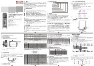
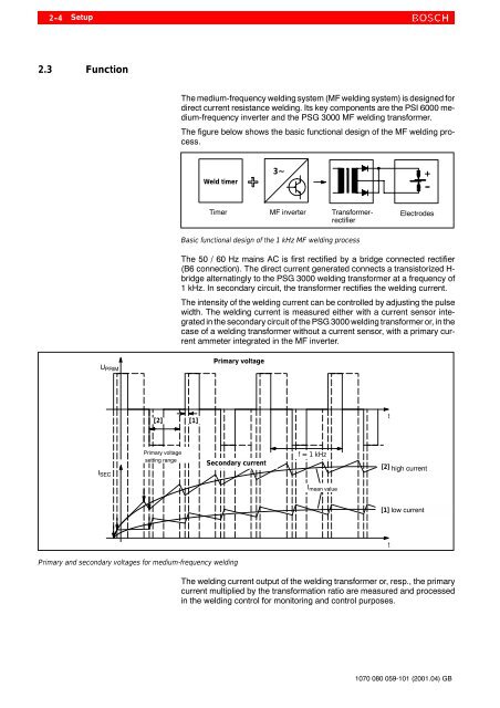
2-4Setup2.3 FunctionThe medium-frequency welding system (MF welding system) is designed fordirect current resistance welding. Its key components are the <strong>PSI</strong> <strong>6000</strong> medium-frequencyinverter and the PSG 3000 MF welding transformer.The figure below shows the basic functional design of the MF welding process.Weld timer3~+---Timer MF inverter TransformerrectifierElectrodesBasic functional design of the 1 kHz MF welding processThe 50 / 60 Hz mains AC is first rectified by a bridge connected rectifier(B6 connection). The direct current generated connects a transistorized H-bridge alternatingly to the PSG 3000 welding transformer at a frequency of1 kHz. In secondary circuit, the transformer rectifies the welding current.The intensity of the welding current can be controlled by adjusting the pulsewidth. The welding current is measured either with a current sensor integratedin the secondary circuit of the PSG 3000 welding transformer or, in thecase of a welding transformer without a current sensor, with a primary currentammeter integrated in the MF inverter.U PRIMPrimary voltage[2] [1]tI SECPrimary voltagesetting rangeSecondary currentf=1kHz[2] high currentI mean value[1] low currenttPrimary and secondary voltages for medium-frequency weldingThe welding current output of the welding transformer or, resp., the primarycurrent multiplied by the transformation ratio are measured and processedin the welding control for monitoring and control purposes.1070 080 059-101 (2001.04) GB