Poppetted Drop Tube with Autolimiter - Franklin Fueling Systems
Poppetted Drop Tube with Autolimiter - Franklin Fueling Systems
Poppetted Drop Tube with Autolimiter - Franklin Fueling Systems

Create successful ePaper yourself
Turn your PDF publications into a flip-book with our unique Google optimized e-Paper software.
Important Safety MessagesEBW equipment is designed to be installed in association <strong>with</strong> volatile hydrocarbon liquids such as gasoline and dieselfuel. Installing or working on this equipment means working in an environment in which these highly flammable liquidsmay be present. Working in such a hazardous environment presents a risk of severe injury or death if these instructionsand standard industry practices are not followed. Read and follow all instructions thoroughly before installing or workingon this, or any other related, equipment.As you read this guide, please be aware of the following symbols and their meanings.WarningCautionWarningWarningWarningWarningCautionThis symbol identifies a warning. A warning sign will appear in the text of this document when a potentiallyhazardous situation may arise if the instructions that follow are not adhered to closely. A potentially hazardoussituation may involve the possibility of severe bodily harm or even death.This is a caution symbol. A caution sign will appear in the text of this document when a potentially hazardousenvironmental situation may arise if the instructions that follow are not adhered to closely. A potentiallyhazardous environmental situation may involve the leakage of fuel from equipment that could severely harmthe environment.Follow all applicable codes governing the installation and servicing of this product and the entiresystem. Always lock out and tag electrical circuit breakers while installing or servicing this equipmentand related equipment. A potentially lethal electrical shock hazard and the possibility of an explosionor fire from a spark can result if the electrical circuit breakers are accidentally turned on duringinstallation or servicing. Please refer to the Installation and Owner’s Manual for this equipment andthe appropriate documentation for any other related equipment for complete installation and safetyinformation.Before entering a containment sump, check for the presence of hydrocarbon vapors. If these vaporsare inhaled they could cause dizziness or unconsciousness, and, if ignited, hydrocarbon vaporscould explode causing serious injury or death. Electronic and electrical petroleum monitoringequipment is often housed in containment sumps designed to trap hazardous liquid spills and preventcontamination of the environment, and, as a consequence, containment sumps can trap dangerousamounts of hydrocarbon vapors. If these vapor levels reach unsafe amounts, ventilate the sump <strong>with</strong>fresh air. While working in the sump, periodically check the atmosphere in the sump, if vapors reachunsafe levels, exit the sump and ventilate it before continuing work. Always have a second personstanding by for assistance when working in, or around, a containment sump.Follow all federal, state, and local laws governing the installation of this product and its associatedsystems. When no other regulations apply, follow NFPA codes 30, 30A, and 70 from the National FireProtection Association. Failure to follow these codes could result in severe injury, death, seriousproperty damage, and/or environmental contamination.Always secure the work area from moving vehicles. The equipment in this manual is usually mountedunderground, so reduced visibility puts service personnel working on this equipment in danger frommoving vehicles entering the work area. To help eliminate these unsafe conditions, secure the areaby using a service truck to block access to the work environment, or by using any other reasonablemeans available to ensure the safety of service personnel.Use only original EBW parts. Substituting EBW parts may cause failure of the device, which, in turn,may create a hazardous condition and/or damage the environment.2
ContentsImportant Safety Messages.................................. 2Introduction............................................................ 3Assembly Instructions, New Site......................... 5Installation Instructions........................................ 6Assembly Instructions, Retrofit Site................... 7Inspection..............................................................8IntroductionEBW’s model 708 automatic shutoff valve is designedto be installed in the 4" (102 mm) riser pipe of anunderground storage tank to reduce the flow by 90% (atapproximately 92% of tank capacity) and shut the flow offat 95% tank capacity. After the valve has been activated,the delivery hose can be drained. The 708 should only beinstalled in a spill containment manhole.Note: Shutoff points are influenced by the specific gravityof stored liquids. These instructions are basedon average performance utilizing all products.This valve was designed to be used as anemergency overfill prevention device only!Note: Determine if the underground storage tanks isequipped <strong>with</strong> a ball float vent valve as shown inFigure 1. If the tank is equipped <strong>with</strong> a ball floatvent-valve, the nipple portion must not extend morethan 3" (76.2 mm) into the tank for this device tofunction properly. If the ball float vent-valve’s nippleextends more than 3" (76.2 mm) from the top ofthe tank, remove it or replace it <strong>with</strong> a 3" (76.2 mm)diameter ball float valve (EBW part #308-300-05) ora 2" (50.8 mm) diameter ball float valve (EBW part#308-213-01).To prevent product spillage from anCaution underground storage tank (UST),well-maintained delivery equipment,a proper connection, and a tightfill adaptor are essential. Deliverypersonnel should inspect deliveryelbows and hoses for damage andmissing parts.Make certain there is a positiveconnection between the adaptorand elbow. If delivery equipmentis not properly maintained or ifan elbow is not securely coupledto an adaptor, a serious spillmay result when an EBW model708 closes causing a hazard andenvironmental contamination.Tools Needed forInstallation and Assembly1/16" ((1.6 mm) and 3/16" (4.7 mm)Drill BitsDrillTape MeasureHalf Round Fine FileHammerHacksaw <strong>with</strong> Fine Tooth BladeScrewdriver - Flat BladeMasking or Electrical TapePop Rivet ToolPermanent Marker3
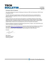
FLOW FRAKLIN FUELING SYSTEM INC.Figure 195%Top of Riser <strong>with</strong> Adaptor Removed705 Spill Containment (Ref.)Vapor RecoveryRiserUpper <strong>Drop</strong> <strong>Tube</strong>Top of Riser“A”“D”Vent Line3" (76.2 mm)MaxTank Riser PipeAuto Limiter II Valve Assy.Top of Tank“B”Ball FloatVent Valvein ExtractorMax.Press.-10 P.S.I.LISTED Automatic Overfill ShutoffGravity Feed Only95% of aFull TankFLOW FRAKLIN FUELING SYSTEM INC.Max.Press.-10 P.S.I.LISTED Automatic Overfill ShutoffGravity Feed Only95%(U.S.T.)“C”Lower <strong>Drop</strong> <strong>Tube</strong>“E”≈ 45°6" (152 mm) Max*Bottom of Tank* Or Per Local RequirementsMeasurement Value Description“A”Distance from the Top of the Riser to the Inside of the Top of the Tank“B”“C”95 % Full Tank Level (See Chart “A” for Your Size Tank)Distance from the Top of the Riser to the Bottom of TankCalculationsD=A+B-5"E = C-D-17-6*Upper <strong>Drop</strong> <strong>Tube</strong> LengthLower <strong>Drop</strong> <strong>Tube</strong> Length4
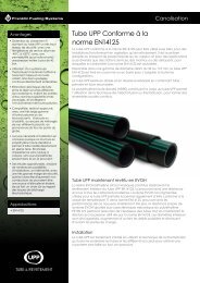
Assembly Instructions:New Site InstallationBefore you begin assembly, clear the inside diameter ofthe riser pipe of any burrs, improper reaming, or foreignmaterial. Failure to adequately clean the inside of the riserpipe may damage or prevent the valve from functioningproperly.1. Determine the 95% shutoff point for your tank fromthe tank chart provided <strong>with</strong> the tank or from acalibrated gauge stick. To determine your actual“B” dimension, subtract the 95% level height fromthe overall tank diameter (tank diameter (inches)- 95% level (inches) = “B” dimension). The chartbelow is provided for reference only (see Figure 1).Your actual “B” dimension will vary slightly basedupon your actual overall tank diameter head andbulkhead design.Tank DiameterAppx. Dimension“B” for 95% Shutoff4 feet (122 cm) 5" (127 mm)5 feet (152 cm) 6" (152 mm)6 feet (183 cm) 7 1/2" (191 mm)7 feet (213 cm) 8" (203 mm)8 feet (244 cm) 9 1/2" (241 mm)9 feet (274 cm) 10 1/2" (267 mm)10 feet (305 cm) 13" (330 mm)12 feet (366 cm) 14" (356 mm)Figure 3: 95% Indication3. Wrap the paper cutting and drilling template tightaround the upper drop tube <strong>with</strong> the bottom’s cutedge aligned <strong>with</strong> the mark from Step 4. Tape thetemplate to the drop tube (see Figure 4).2. Measure down from the bottom edge of the coaxialadapter and mark dimension “D” on the drop tube(see Figure 2).Figure 4: Apply Template4. Carefully drill four 1/16" pilot holes through the droptube, using the drill template’s center lines (seeFigure 7). Enlarge each 1/16" hole to 3/16".Figure 2: Measure from Bottom EdgeFigure 5: Drill Pilot Holes5
5. Carefully saw through the drop tube — rotating thetube while sawing will help prevent run-out (seeFigure 8). After sawing: remove the hose clamp, filethe end square, and remove all burrs.Male ThreadsFigure 8: Thread <strong>Drop</strong> <strong>Tube</strong>Figure 6: Saw6. Install the appropriate o-ring into the I.D. groove atthe top of the valve (see Figure 7).9. Mark dimension “E” on the lower end of the lowerdrop tube. Cut the tube at this mark at 45º andde-burr (see Figure 9). Also, the lowest point ofthe drop tube must not project <strong>with</strong>in the minimumclearance specified by the tank manufacturer.Note: Coating the O-rings in petroleum jelly may assist ininstalling the upper drop tube to the Auto Limiter.6Figure 7: Install O-Ring7. Install four 3/16" (4.76 mm) diameter closed-endrivets into the holes discussed in Step 5. Use onlythe rivets supplied. The heads of the rivets mustbe flush or below the exterior surface of the upperdrop tube or valve body.8. Take the bottom of the Auto Limiter and apply fuelresistant pipe sealant to the male threads on thebottom of the valve assembly. Thread the lowerdrop tube on all of the way to the stop shoulder.If a vise or clamp is used to hold the assemblyin place, make sure to avoid clamping near anymoving parts (see Figure 8).Figure 9: De-burr the <strong>Tube</strong>Installation Instructions10. Double-check the 95% shutoff length of theassembly. Measure from the bottom edge of thecoaxial adapter (Figure 2) to the 95% mark on thevalve (Figure 3). It should be approximately A+B-1"(See page 4).11. Check the inside diameter of the riser pipe forany burrs, improper reaming, or foreign material.Failure to clean the inside diameter of the riser pipemay damage or prevent the valve from functioningproperly.12. Apply fuel-resistant pipe sealant to the tank riserthreads.13. Check the exposed floats for freedom of movement.If the floats drag, inspect the guide bar for damage.Both the floats should be free to move up anddown <strong>with</strong>out drag.14. Carefully lower the complete shutoff assemblydown the riser pipe. Hold the unit by the upperdrop tube only (see Figure 16). Do not force thevalve down the riser pipe. If the valve does not fit,the riser pipe will have to be cleaned or deburredbefore inserting the valve.15. Tighten the coaxial adapter to the tank riser.
Assembly Instruction:Retrofit Site Install1. Remove the fill adapter and pull out the existingdrop tube overfill prevention device2. Drill out the rivets holding the upper drop tube tothe <strong>Autolimiter</strong> II, and remove the upper drop tube3. Measure & record the upper drop tube length =_______a. If replacing a non-poppetted coaxial drop tube,measure from the underside of the support lugs(see Figure 10).Figure 12: Apply Template7. Carefully drill four 1/16” pilot holes through the droptube, using the drill template’s center lines (seeFigure 13). Enlarge each 1/16” hole to 3/16”.Figure 10: Measuring for Replacing Coaxialb. If replacing a non-coaxial drop tube, measurefrom the underside of the flange (see Figure 11).Figure 13: Drill Pilot Holes8. Carefully saw through the drop tube — rotating thetube while sawing will help prevent run-out (seeFigure 14). After sawing: remove the hose clamp,file the end square, and remove all burrs.Figure 11: Measuring for Replacing non-Coaxial4. Subtract 1” from the measurement from the “old”upper drop tube = _______5. Mark this length on the new poppetted coaxialupper drop tube measuring from the bottom edgeof the coaxial adapter (Figure 2).6. Wrap the paper cutting and drilling template tightaround the upper drop tube <strong>with</strong> the bottom’s cutedge aligned <strong>with</strong> the mark from Step 5. Tape thetemplate to the drop tube (see Figure 12).Figure 14: Saw6. Install the appropriate o-ring into the I.D. groove atthe top of the valve (see Figure 15).Note: Coating the O-rings in petroleum jelly may assist ininstalling the upper drop tube to the Auto Limiter.7
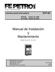
Figure 17: Inspect Floats and Linkage4. Insert the 1/8” T-handled hex wrench into the openhole until it makes contact <strong>with</strong> the internal valveflapper (see Figure 18).Figure 20: View from Top of <strong>Drop</strong>tube8. Slide the second float away from the hex wrench(see Figure 21). This will release the valve’ssecond stage flapper (see Figure 22).Figure 18: Insert Hex Wrench5. While holding both floats from sliding away fromthe inserted hex wrench, lightly try to push the hexwrench further into the hole. The flapper shouldstay in the locked position and not move closed.If the flapper closes, the latching mechanism isdefective and valve must be replaced.6. Slide the float closest to the hex wrench away fromthe wrench. You should now be able to easily pushthe hex wrench further into the hole. This will closethe first stage valve flapper (see Figure 19).Figure 21: Slide Second FloatFigure 22: Second Stage FlapperFigure 19: Slide Float7. With the hex wrench inserted until it will not go anyfurther, the first stage valve flapper should stayin the closed position. Using a flashlight, you cannow see this by looking in from the top of the droptube (see Figure 20).9. Remove the hex wrench from the inspection port.The valve’s internal flappers should return totheir open positions. To verify that the flapper hasreset and re-latched, re-insert the hex wrench andrepeat Steps 4 & 5. If the flapper did not reset,replace the valve.10. Remove the hex wrench and re-install the #10-24inspection port screw <strong>with</strong> an o-ring seal attached.Torque the screw to 20-25 in. lbs.9
11. From the end of the drop tube’s top flange,illuminate the internal valve flapper <strong>with</strong> a flashlightand visually inspect the deflector attached to thevalve flapper. There should be no visible damageto this deflector. The deflector’s shape should beuniform and similar to that of Figure 23. If damageis observed, the valve will not operate as designedand must be replaced.Figure 23: Deflector Shape12. After completing these inspection steps, recheckthe floats and linkage as detailed in Steps 2 & 3.Using care not to damage the floats or the floatguide, reinstall the drop tube assembly into thetank riser.10
Page intentionally blank
©2012 EBW F-9037 Rev. 1