Cisco WAP200 Wireless-G Access Point with PoE and ...
Cisco WAP200 Wireless-G Access Point with PoE and ...
Cisco WAP200 Wireless-G Access Point with PoE and ...

Create successful ePaper yourself
Turn your PDF publications into a flip-book with our unique Google optimized e-Paper software.
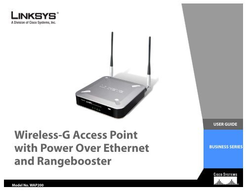
<strong>Wireless</strong>-G <strong>Access</strong> <strong>Point</strong><strong>with</strong> Power Over Ethernet<strong>and</strong> RangeboosterUSER GUIDEBUSINESS SERIESModel No. <strong>WAP200</strong>
<strong>Wireless</strong>-G <strong>Access</strong> <strong>Point</strong> <strong>with</strong> Power Over Ethernet <strong>and</strong> RangeboosterCopyright <strong>and</strong> TrademarksSpecifications are subject to change <strong>with</strong>out notice. Linksys, <strong>Cisco</strong> <strong>and</strong> the <strong>Cisco</strong> Logo are registered trademarksor trademarks of <strong>Cisco</strong> Systems, Inc. <strong>and</strong>/or its affiliates in the U.S. <strong>and</strong> certain other countries. Copyright © 2008<strong>Cisco</strong> Systems, Inc. All rights reserved.WARNING: This product contains chemicals, including lead, knownto the State of California to cause cancer, <strong>and</strong> birth defects or otherreproductive harm. Wash h<strong>and</strong>s after h<strong>and</strong>ling.How to Use this User GuideThe user guide to the Dual-B<strong>and</strong> <strong>Wireless</strong> <strong>Access</strong> <strong>Point</strong> has been designed to make underst<strong>and</strong>ing networking<strong>with</strong> the <strong>Access</strong> <strong>Point</strong> easier than ever. Look for the following items when reading this User Guide:This checkmark means there is a note of interest <strong>and</strong>is something you should pay special attention to whileusing the <strong>Access</strong> <strong>Point</strong>.This exclamation point means there is a caution orwarning <strong>and</strong> is something that could damage yourproperty or the <strong>Access</strong> <strong>Point</strong>.This question mark provides you <strong>with</strong> a reminder aboutsomething you might need to do while using the <strong>Access</strong> <strong>Point</strong>.definitions for technical terms that are presented like this:word: definition.In addition to these symbols, there areAlso, each figure (diagram, screenshot, or other image) is provided <strong>with</strong> a figure number <strong>and</strong> description, likethis:Figure 0-1: Sample Figure DescriptionFigure numbers <strong>and</strong> descriptions can also be found in the “List of Figures” section.<strong>WAP200</strong>-UG-8062710B-RC
<strong>Wireless</strong>-G <strong>Access</strong> <strong>Point</strong> <strong>with</strong> Power Over Ethernet <strong>and</strong> RangeboosterTable of ContentsChapter 1: Introduction 1Welcome 1What’s in this User Guide? 2Chapter 2: Planning Your <strong>Wireless</strong> Network 4Network Topology 4Roaming 4Network Layout 5Example of a simple wireless network 6Chapter 3: Getting to Know the <strong>Wireless</strong>-G <strong>Access</strong> <strong>Point</strong> 7The LEDs 7The Ports 8Antennas <strong>and</strong> Positions 9Chapter 4: Connecting the <strong>Wireless</strong>-G <strong>Access</strong> <strong>Point</strong> 10Overview 10Connection 10Placement Options 11Chapter 5: Setting Up the <strong>Wireless</strong>-G <strong>Access</strong> <strong>Point</strong> 12Overview 12<strong>Access</strong>ing the Utility 12Navigating the Utility 13Chapter 6: Configuring the <strong>Wireless</strong>-G <strong>Access</strong> <strong>Point</strong> 16The Setup - Basic Setup Tab 16The Setup - Time Tab 17The <strong>Wireless</strong> - Basic <strong>Wireless</strong> Settings Tab 18The <strong>Wireless</strong> - <strong>Wireless</strong> Security Tab 19The <strong>Wireless</strong> - <strong>Wireless</strong> Connection Control Tab 24The <strong>Wireless</strong> - Advanced <strong>Wireless</strong> Settings Tab 25The <strong>Wireless</strong> - VLAN & QoS Tab 26The AP Mode Tab 28The Security Monitor - Basic Settings Tab 31The Security Monitor - Event Log Tab 32The Administration - Management Tab 34
<strong>Wireless</strong>-G <strong>Access</strong> <strong>Point</strong> <strong>with</strong> Power Over Ethernet <strong>and</strong> RangeboosterThe Administration - Log Tab 36The Administration - Factory Default Tab 37The Administration - Firmware Upgrade Tab 37The Administration - Reboot Tab 38The Administration - Config Management Tab 38The Status - Local Network Tab 39The Status - <strong>Wireless</strong> Tab 40The Status - System Performance Tab 41Appendix A: Troubleshooting 43Frequently Asked Questions 43Appendix B: <strong>Wireless</strong> Security 47Security Precautions 47Security Threats Facing <strong>Wireless</strong> Networks 47Appendix C: Upgrading Firmware 50Appendix D: Windows Help 51Appendix E: Glossary 52Appendix F: Specifications 57Appendix G: Warranty Information 60Appendix H: Regulatory Information 61Appendix I: Contact Information 68
<strong>Wireless</strong>-G <strong>Access</strong> <strong>Point</strong> <strong>with</strong> Power Over Ethernet <strong>and</strong> RangeboosterList of FiguresFigure 2-1: Example of a Simple <strong>Wireless</strong> Network 6Figure 3-1: Front Panel 7Figure 3-2: Back View 8Figure 3-3: Desktop Placement <strong>and</strong> Antenna Setup 9Figure 4-1: Connect the Ethernet Cable 10Figure 4-2: Connect the Power 10Figure 4-3: St<strong>and</strong> 11Figure 4-4: Mounting Dimensions 11Figure 5-1: Login Screen 13Figure 6-1: Setup - Basic Setup 16Figure 6-2: Setup - Time 17Figure 6-3: <strong>Wireless</strong> - Basic <strong>Wireless</strong> Settings 18Figure 6-4: <strong>Wireless</strong> - <strong>Wireless</strong> Security (Disabled) 19Figure 6-5: <strong>Wireless</strong> - <strong>Wireless</strong> Security (WEP) 19Figure 6-6: <strong>Wireless</strong> - <strong>Wireless</strong> Security (WPA-Personal) 20Figure 6-7: <strong>Wireless</strong> - <strong>Wireless</strong> Security (WPA2-Personal) 20Figure 6-8: <strong>Wireless</strong> - <strong>Wireless</strong> Security (WPA2-Personal Mixed) 21Figure 6-9: <strong>Wireless</strong> - <strong>Wireless</strong> Security (WPA-Enterprise) 21Figure 6-10: <strong>Wireless</strong> - <strong>Wireless</strong> Security (WPA2-Enterprise) 22Figure 6-11: <strong>Wireless</strong> - <strong>Wireless</strong> Security (WPA2 - Enterprise Mixed) 22Figure 6-12: <strong>Wireless</strong> - <strong>Wireless</strong> Security (RADIUS) 23Figure 6-13: <strong>Wireless</strong> - <strong>Wireless</strong> Connection Control 24Figure 6-14: Select MAC Address from <strong>Wireless</strong> Client List 24Figure 6-15: <strong>Wireless</strong> - Advanced <strong>Wireless</strong> 25Figure 6-16: <strong>Wireless</strong> - VLAN & QoS 26Figure 6-17: AP Mode 28Figure 6-18: <strong>Wireless</strong> Repeater Mode 29Figure 6-19: <strong>Wireless</strong> Bridge Mode 30
<strong>Wireless</strong>-G <strong>Access</strong> <strong>Point</strong> <strong>with</strong> Power Over Ethernet <strong>and</strong> RangeboosterFigure 6-20: Security Monitor - Basic Settings 31Figure 6-21: Security Monitor - Event Log 32Figure 6-22: Administration - Management 34Figure 6-23: Administration - Log 36Figure 6-24: Administration - Factory Default 37Figure 6-25: Administration - Firmware Upgrade 37Figure 6-26: Administration - Reboot 38Figure 6-27: Administration - Config Management 38Figure 6-28: Status - Local Network 39Figure 6-29: Status - <strong>Wireless</strong> 40Figure 6-30: Status - System Performance 41Figure 6-31: Status - <strong>Wireless</strong> 41Figure 6-32: Status - System Performance 41Figure C-1: Firmware Upgrade 50
<strong>Wireless</strong>-G <strong>Access</strong> <strong>Point</strong> <strong>with</strong> Power Over Ethernet <strong>and</strong> RangeboosterChapter 1: IntroductionWelcomeThank you for choosing the <strong>Wireless</strong>-G <strong>Access</strong> <strong>Point</strong> <strong>with</strong> Power Over Ethernet <strong>and</strong> Rangebooster. This <strong>Access</strong><strong>Point</strong> will allow you to network wirelessly better than ever.How does the <strong>Access</strong> <strong>Point</strong> do all of this? An access point allows for greater range <strong>and</strong> mobility <strong>with</strong>in yourwireless network while also allowing you to connect the wireless network to a wired environment. In fact, the<strong>Wireless</strong>-G <strong>Access</strong> <strong>Point</strong> <strong>with</strong> Power Over Ethernet <strong>and</strong> Rangebooster can support communications on up to fourwireless networks, using Virtual Local Area Network (VLAN) technology.The <strong>Wireless</strong>-G <strong>Access</strong> <strong>Point</strong> <strong>with</strong> Power Over Ethernet <strong>and</strong> Rangebooster also offers the convenience of Powerover Ethernet (<strong>PoE</strong>) capability, so it can receive data <strong>and</strong> power over a single Ethernet network cable. You caneven connect wired networks in two different buildings, by using two <strong>Access</strong> <strong>Point</strong>s set to <strong>Wireless</strong> Bridge mode.But what does all of this mean?Networks are useful tools for sharing computer resources. You can access one printer from different computers<strong>and</strong> access data located on another computer's hard drive. Networks are even used for playing multiplayer videogames. So, networks are not only useful in homes <strong>and</strong> offices, they can also be fun.PCs on a wired network create a LAN, or Local Area Network. They are connected <strong>with</strong> Ethernet cables, which iswhy the network is called “wired”.PCs equipped <strong>with</strong> wireless client cards or adapters can communicate <strong>with</strong>out cumbersome cables. By sharingthe same wireless settings, <strong>with</strong>in their transmission radius, they form a wireless network. This is sometimescalled a WLAN, or <strong>Wireless</strong> Local Area Network. The <strong>Access</strong> <strong>Point</strong> bridges wireless networks of both 802.11g <strong>and</strong>802.11b st<strong>and</strong>ards <strong>and</strong> wired networks.Use the instructions in this Guide to help you connect the <strong>Access</strong> <strong>Point</strong>, set it up, <strong>and</strong> configure it to bridge yourdifferent networks. These instructions should be all you need to get the most out of the <strong>Access</strong> <strong>Point</strong>.access point: a device that allows wireless-equippedcomputers <strong>and</strong> other devices to communicate <strong>with</strong> eachother <strong>and</strong> <strong>with</strong> devices on a wired network. Also used toexp<strong>and</strong> the range of a wireless network.network: a series of computers or devices connectedtogether.lan (local area network): the computers <strong>and</strong> networkingdevices that make up your local network.poe (power over ethernet): a technology enabling anEthernet network cable to deliver both data <strong>and</strong> power.ethernet: network protocol defined in IEEE 802.3 st<strong>and</strong>ardthat specifies how data is placed on <strong>and</strong> retrieved from acommon transmission medium.adapter: a device that adds network functionality to yourPC.802.11g: a wireless networking st<strong>and</strong>ard that specifies amaximum data transfer rate of 54Mbps, an operatingfrequency of 2.4GHz, <strong>and</strong> backward compatibility <strong>with</strong>802.11b devices.802.11b: a wireless networking st<strong>and</strong>ard that specifies amaximum data transfer rate of 11Mbps <strong>and</strong> an operatingfrequency of 2.4GHz.Chapter 1: IntroductionWelcome1
<strong>Wireless</strong>-G <strong>Access</strong> <strong>Point</strong> <strong>with</strong> Power Over Ethernet <strong>and</strong> RangeboosterWhat’s in this User Guide?This user guide covers the steps for setting up <strong>and</strong> using the <strong>Wireless</strong>-G <strong>Access</strong> <strong>Point</strong>.• Chapter 1: IntroductionThis chapter describes the <strong>Wireless</strong>-G <strong>Access</strong> <strong>Point</strong>’s applications <strong>and</strong> this User Guide.• Chapter 2: Planning your <strong>Wireless</strong> NetworkThis chapter describes the basics of wireless networking.• Chapter 3: Getting to Know the <strong>Wireless</strong>-G <strong>Access</strong> <strong>Point</strong>This chapter describes the physical features of the <strong>Access</strong> <strong>Point</strong>.• Chapter 4: Connecting the <strong>Wireless</strong>-G <strong>Access</strong> <strong>Point</strong>This chapter instructs you on how to connect your <strong>Access</strong> <strong>Point</strong> to your network <strong>and</strong> placement options.• Chapter 5: Setting up the <strong>Wireless</strong>-G <strong>Access</strong> <strong>Point</strong>This chapter explains how to perform the most basic setting changes through the web-based utility.• Chapter 6: Configuring the <strong>Wireless</strong>-G <strong>Access</strong> <strong>Point</strong>This chapter provides a reference for the available configuration through the web-based utility.• Appendix A: TroubleshootingThis appendix describes some frequently asked questions regarding installation <strong>and</strong> use of the <strong>Wireless</strong>-G<strong>Access</strong> <strong>Point</strong> <strong>with</strong> Power Over Ethernet <strong>and</strong> Rangebooster.• Appendix B: <strong>Wireless</strong> SecurityThis appendix explains the risks of wireless networking <strong>and</strong> some solutions to reduce the risks.• Appendix C: Upgrading FirmwareThis appendix instructs you on how to upgrade the <strong>Access</strong> <strong>Point</strong>’s firmware.• Appendix D: Windows Help.This appendix describes some of the ways Windows can help you <strong>with</strong> wireless networking.• Appendix E: GlossaryThis appendix gives a brief glossary of terms frequently used in networking.• Appendix F: SpecificationsThis appendix provides the <strong>Access</strong> <strong>Point</strong>’s technical specifications.Chapter 1: IntroductionWhat’s in this User Guide?2
<strong>Wireless</strong>-G <strong>Access</strong> <strong>Point</strong> <strong>with</strong> Power Over Ethernet <strong>and</strong> Rangebooster• Appendix G: Warranty InformationThis appendix supplies the <strong>Access</strong> <strong>Point</strong>’s warranty information.• Appendix H: Regulatory InformationThis appendix supplies the <strong>Access</strong> <strong>Point</strong>’s regulatory information.• Appendix I: Contact InformationThis appendix provides contact information for a variety of Linksys resources, including Technical Support.Chapter 1: IntroductionWhat’s in this User Guide?3
<strong>Wireless</strong>-G <strong>Access</strong> <strong>Point</strong> <strong>with</strong> Power Over Ethernet <strong>and</strong> RangeboosterChapter 2: Planning Your <strong>Wireless</strong> NetworkNetwork TopologyA wireless network is a group of computers, each equipped <strong>with</strong> one or more wireless adapters. Computers in awireless network must be configured to share the same radio channel to talk to each other. Several PCs equipped<strong>with</strong> wireless cards or adapters can communicate <strong>with</strong> each other to form an ad-hoc network <strong>with</strong>out the use ofan access point.Linksys also provides products to allow wireless adaptors to access wired network through a bridge such as thewireless access point, or wireless router. An integrated wireless <strong>and</strong> wired network is called an infrastructurenetwork. Each wireless PC in an infrastructure network can talk to any computer in a wired or wireless networkvia the access point or wireless router.ad-hoc: a group of wireless devices communicating directly<strong>with</strong> each other (peer-to-peer) <strong>with</strong>out the use of an accesspoint.infrastructure: a wireless network that is bridged to a wirednetwork via an access point.An infrastructure configuration extends the accessibility of a wireless PC to a wired network, <strong>and</strong> may double theeffective wireless transmission range for two wireless adapter PCs. Since an <strong>Access</strong> <strong>Point</strong> is able to forward data<strong>with</strong>in a network, the effective transmission range in an infrastructure network may be more than doubled since<strong>Access</strong> <strong>Point</strong> can transmit signal at higher power to the wireless space.RoamingInfrastructure mode also supports roaming capabilities for mobile users. Roaming means that you can move yourwireless PC <strong>with</strong>in your network <strong>and</strong> the access points will pick up the wireless PC's signal, providing that theyboth share the same wireless network (SSID), wireless channel, <strong>and</strong> wireless security settings.This <strong>Access</strong> <strong>Point</strong> has 802.11F Inter-<strong>Access</strong> <strong>Point</strong> Protocol (IAPP) to complete the roaming process in seconds. Ifyour wireless networks share the same IP subnet, this will not disrupt your data connection while moving around.roaming: the ability to take a wireless device from oneaccess point's range to another <strong>with</strong>out losing theconnection.ssid: your wireless network's nameBefore you consider roaming, choose a feasible radio channel <strong>and</strong> optimum access point position. Proper accesspoint positioning combined <strong>with</strong> a clear radio signal will greatly enhance performance.Chapter 2: Planning Your <strong>Wireless</strong> NetworkNetwork Topology4
<strong>Wireless</strong>-G <strong>Access</strong> <strong>Point</strong> <strong>with</strong> Power Over Ethernet <strong>and</strong> RangeboosterNetwork LayoutThe <strong>Wireless</strong>-G <strong>Access</strong> <strong>Point</strong> <strong>with</strong> Power Over Ethernet <strong>and</strong> Rangebooster has been designed for use <strong>with</strong>802.11g <strong>and</strong> 802.11b products. The <strong>Access</strong> <strong>Point</strong> is compatible <strong>with</strong> 802.11g <strong>and</strong> 802.11b adapters, such as thenotebook adapters for your laptop computers, PCI adapters for your desktop PCs, <strong>and</strong> USB adapters for all PCswhen you want to enjoy wireless connectivity. These wireless products can also communicate <strong>with</strong> an 802.11g or802.11b wireless print server (if available).To link your wired network <strong>with</strong> your wireless network, connect the <strong>Access</strong> <strong>Point</strong>’s Ethernet network port to anyswitch or router <strong>with</strong> Power over Ethernet (<strong>PoE</strong>)—or a <strong>PoE</strong> injector, such as the Linksys WAPPOE or WAPPOE12.Note that the 12 VDC on the WAPPOE12 is for the splitter output. Both <strong>PoE</strong> Injectors provide 48 VDC power output.With these, <strong>and</strong> many other, Linksys products, your networking options are limitless. Go to the Linksys website atwww.linksys.com for more information about wireless products.Chapter 2: Planning Your <strong>Wireless</strong> NetworkNetwork Layout5
<strong>Wireless</strong>-G <strong>Access</strong> <strong>Point</strong> <strong>with</strong> Power Over Ethernet <strong>and</strong> RangeboosterExample of a simple wireless networkFigure 2-1: Example of a Simple <strong>Wireless</strong> NetworkThe above diagram shows a typical infrastructure wireless network setup. The wireless <strong>Access</strong> <strong>Point</strong>s areconnecting to a Linksys switch that provides power to the <strong>Access</strong> <strong>Point</strong>s. Each <strong>Access</strong> <strong>Point</strong> can connect multiplewireless devices to the network. This network will provide connectivity among wireless network devices <strong>and</strong> PCsthat have a wired connection to the switch.The switch then can connect to a router that can connect to an ISP to reach global Internet.Chapter 2: Planning Your <strong>Wireless</strong> NetworkExample of a simple wireless network6
<strong>Wireless</strong>-G <strong>Access</strong> <strong>Point</strong> <strong>with</strong> Power Over Ethernet <strong>and</strong> RangeboosterChapter 3: Getting to Know the <strong>Wireless</strong>-G <strong>Access</strong> <strong>Point</strong>The LEDsThe <strong>Access</strong> <strong>Point</strong>'s LEDs, where information about network activity is displayed, are located on the front panel.Figure 3-1: Front PanelPower<strong>PoE</strong>WIRELESSETHERNETGreen. The Power LED lights up when the <strong>Access</strong> <strong>Point</strong> is powered on.Green. The <strong>PoE</strong> LED lights up when the <strong>Access</strong> <strong>Point</strong> is powered through Ethernet cable.Green. The WIRELESS LED lights up when the wireless module is active on the <strong>Access</strong> <strong>Point</strong>. Ifthe <strong>Wireless</strong> LED is flashing, the <strong>Access</strong> <strong>Point</strong> is actively sending to or receiving data from awireless device.Green. The ETHERNET LED lights up when the <strong>Access</strong> <strong>Point</strong> is successfully connected to adevice through the Ethernet network port. If the ETHERNET LED is flashing, the <strong>Access</strong> <strong>Point</strong> isactively sending to or receiving data from one of the devices over the Ethernet network port.Chapter 3: Getting to Know the <strong>Wireless</strong>-G <strong>Access</strong> <strong>Point</strong>The LEDs7
<strong>Wireless</strong>-G <strong>Access</strong> <strong>Point</strong> <strong>with</strong> Power Over Ethernet <strong>and</strong> RangeboosterThe PortsThe <strong>Access</strong> <strong>Point</strong>’s port are located on the back of the device.port: the connection point on a computer ornetworking device used for plugging incables or adaptersFigure 3-2: Back ViewReset ButtonEthernetPowerThere are two ways to reset the <strong>Access</strong> <strong>Point</strong> to the factory default configuration. Either pressthe Reset button, for approximately ten seconds, or restore the defaults using the <strong>Access</strong><strong>Point</strong>'s web-based utility.The Ethernet network port connects to Ethernet network devices, such as a switch or routerthat may or may not support Power over Ethernet (<strong>PoE</strong>).The Power port connects to the supplied power adapter.IMPORTANT: Resetting the <strong>Access</strong> <strong>Point</strong> willerase all of your settings (including wirelesssecurity, IP address, <strong>and</strong> SSID) <strong>and</strong> replacethem <strong>with</strong> the factory defaults. Do not resetthe <strong>Access</strong> <strong>Point</strong> if you want to retain thesesettings.Chapter 3: Getting to Know the <strong>Wireless</strong>-G <strong>Access</strong> <strong>Point</strong>The Ports8
<strong>Wireless</strong>-G <strong>Access</strong> <strong>Point</strong> <strong>with</strong> Power Over Ethernet <strong>and</strong> RangeboosterAntennas <strong>and</strong> PositionsThe <strong>Access</strong> <strong>Point</strong>’s antennas are located on the back of the device. The <strong>Access</strong> <strong>Point</strong> can be placed on a desktopor wall-mounted. When placed on a desktop, the <strong>Access</strong> <strong>Point</strong> can be stacked <strong>with</strong> other Linksys Business Seriesproducts.AntennaThe <strong>Access</strong> <strong>Point</strong> has two detachable 2dBi omni-directional antennas. Adjust the two antennasso that they form a 90 degree angle for best MIMO range performance.Figure 3-3: Desktop Placement <strong>and</strong> Antenna SetupChapter 3: Getting to Know the <strong>Wireless</strong>-G <strong>Access</strong> <strong>Point</strong>Antennas <strong>and</strong> Positions9
<strong>Wireless</strong>-G <strong>Access</strong> <strong>Point</strong> <strong>with</strong> Power Over Ethernet <strong>and</strong> RangeboosterChapter 4: Connecting the <strong>Wireless</strong>-G <strong>Access</strong> <strong>Point</strong>OverviewThis chapter explains how to place <strong>and</strong> connect the <strong>Access</strong> <strong>Point</strong>.Depending on your application, you might want to set up the device first before mounting the device. Refer to“Chapter 5: Setting Up the <strong>Wireless</strong>-G <strong>Access</strong> <strong>Point</strong>”.hardware: the physical aspect ofcomputers, telecommunications, <strong>and</strong>other information technology devices.Connection1. Connect your Ethernet network cable to your network router or switch. Then connect the other end of thenetwork cable to the <strong>Access</strong> <strong>Point</strong>’s Ethernet port.2. If you are using Power Over Ethernet (POE), proceed to the following section, “Placement Options.”If you are not using POE, then connect the included power adapter to the <strong>Access</strong> <strong>Point</strong>’s Power port. Then plugthe power adapter into an electrical outlet. The LEDs on the front panel will light up as soon as the <strong>Access</strong><strong>Point</strong> powers on.Figure 4-1: Connect the Ethernet CableProceed to the following section, “Placement Options.”Figure 4-2: Connect the PowerChapter 4: Connecting the <strong>Wireless</strong>-G <strong>Access</strong> <strong>Point</strong>Overview10
<strong>Wireless</strong>-G <strong>Access</strong> <strong>Point</strong> <strong>with</strong> Power Over Ethernet <strong>and</strong> RangeboosterPlacement OptionsThere are three ways to place the <strong>Wireless</strong>-G <strong>Access</strong> <strong>Point</strong>. The first way is to place it horizontally on a surface, soit sits on its four rubber feet. The second way is to st<strong>and</strong> the <strong>Access</strong> <strong>Point</strong> vertically on a surface. The third way isto mount it on a wall. The st<strong>and</strong> <strong>and</strong> wall-mount options are explained in further detail below.St<strong>and</strong> Option1. Locate the <strong>Access</strong> <strong>Point</strong>’s left side panel.2. The <strong>Access</strong> <strong>Point</strong> includes two st<strong>and</strong>s. With the two large prongs facing outward, insert the short prongs intothe little slots in the <strong>Access</strong> <strong>Point</strong>, <strong>and</strong> push the st<strong>and</strong> upward until it snaps into place.LargeProngsRepeat this step <strong>with</strong> the other st<strong>and</strong>.Now that the hardware installation is complete, proceed to “Chapter 5: Setting up the <strong>Wireless</strong>-G <strong>Access</strong><strong>Point</strong>,” for directions on how to set up the <strong>Access</strong> <strong>Point</strong>.Figure 4-3: St<strong>and</strong>Wall-Mount Option1. On the <strong>Access</strong> <strong>Point</strong>’s back panel are two crisscross wall-mount slots.2. Determine where you want to mount the <strong>Access</strong> <strong>Point</strong>, <strong>and</strong> install two screws that are 2-15/16" apart.2-15/16"3. Line up the <strong>Access</strong> <strong>Point</strong> so that the wall-mount slots line up <strong>with</strong> the two screws.4. Place the wall-mount slots over the screws <strong>and</strong> slide the <strong>Access</strong> <strong>Point</strong> down until the screws fit snugly intothe wall-mount slots.Now that the hardware installation is complete, proceed to “Chapter 5: Setting up the <strong>Wireless</strong>-G <strong>Access</strong><strong>Point</strong>,” for directions on how to set up the <strong>Access</strong> <strong>Point</strong>.Figure 4-4: Mounting DimensionsChapter 4: Connecting the <strong>Wireless</strong>-G <strong>Access</strong> <strong>Point</strong>Placement Options11
<strong>Wireless</strong>-G <strong>Access</strong> <strong>Point</strong> <strong>with</strong> Power Over Ethernet <strong>and</strong> RangeboosterChapter 5: Setting Up the <strong>Wireless</strong>-G <strong>Access</strong> <strong>Point</strong>OverviewThe <strong>Access</strong> <strong>Point</strong> has been designed to be functional right out of the box <strong>with</strong> the default settings. However, ifyou'd like to change these settings, the <strong>Access</strong> <strong>Point</strong> can be configured through your web browser <strong>with</strong> theweb-based Utility. This chapter explains how to use the Utility to perform the most basic settings.The Utility can be accessed via web browsers, such as Microsoft Internet Explorer or Mozilla Firefox through theuse of a computer that is networked <strong>with</strong> the <strong>Access</strong> <strong>Point</strong>.For a basic network setup, most users only have to use the following screens of the Utility:• SetupOn the Setup screen, enter your basic network settings (IP address) here.• ManagementClick the Administration tab <strong>and</strong> then select the Management screen. The <strong>Access</strong> <strong>Point</strong>’s default passwordis admin. To secure the <strong>Access</strong> <strong>Point</strong>, change the AP Password from its default.HAVE YOU: Enabled TCP/IP on your PCs? PCscommunicate over the network <strong>with</strong> thisprotocol. Refer to “Appendix D: Windows Help”for more information on TCP/IP.tcp/ip: a set of protocols PCs use tocommunicate over a network.browser: an application that provides a way tolook at <strong>and</strong> interact <strong>with</strong> all the information on theWorld Wide Web.Most users will also customize their wireless settings:• <strong>Wireless</strong>On the <strong>Wireless</strong> screen, change default SSID under the Basic <strong>Wireless</strong> Settings Tab. Select the level ofsecurity under the <strong>Wireless</strong> Security Tab <strong>and</strong> complete the options for the selected security mode.<strong>Access</strong>ing the UtilityThere are three ways to connect to your <strong>Access</strong> <strong>Point</strong> for the first time.1. If you have a 48VDC Power Injector (e.g. Linksys WAPPOE), power up your <strong>Access</strong> <strong>Point</strong> first, then connect theInjector’s cable to your PC. Configure your PC to have the static IP address on the same subnet as the <strong>Access</strong><strong>Point</strong>’s default IP address (192.168.1.245).2. If you have a <strong>PoE</strong> switch (e.g. Linksys SRW224P), connect your <strong>Access</strong> <strong>Point</strong> <strong>and</strong> your PC to the samenetwork. Configure your PC to have the static IP address on the same subnet as the <strong>Access</strong> <strong>Point</strong>’s default IPaddress (192.168.1.245). Or if there is a DHCP server connected to the switch, configure it to assign the IPaddress in 192.168.1.0/24 subnet. Your PC will get an IP address in the subnet through the DHCP.Chapter 5: Setting Up the <strong>Wireless</strong>-G <strong>Access</strong> <strong>Point</strong>Overview12
<strong>Wireless</strong>-G <strong>Access</strong> <strong>Point</strong> <strong>with</strong> Power Over Ethernet <strong>and</strong> Rangebooster3. Although it is not recommended, you can connect your PC wirelessly to the <strong>Access</strong> <strong>Point</strong> when the DHCPserver is connected on the LAN side. It is not recommended, because you can easily lose your connectionthrough configuration changes.Launch your web browser, such as Internet Explorer or Mozilla Firefox <strong>and</strong> enter the <strong>Access</strong> <strong>Point</strong>’s default IPaddress, 192.168.1.245, in the Address field. Press the Enter key.Enter admin in the User Name field. The first time you open the web-based utility, use the default password,admin. (You can set a new password from the Administration - Management tab.) Then click the OK button.After setting up the <strong>Access</strong> <strong>Point</strong> to use DHCP or manually configure a new IP address, move your <strong>Access</strong> <strong>Point</strong> tothe desired network. You will have to use the new IP address the next time you access the web-based utility.Navigating the UtilityThe web-based utility consists of the following five main tabs: Setup, <strong>Wireless</strong>, Security Monitor, Administration,<strong>and</strong> Status. Additional screens (sub tabs) will be available from most of the main tabs.The following briefly describes the main & sub tabs of the Utility.SetupFigure 5-1: Login ScreenEnter the Host Name, IP Address settings, <strong>and</strong> set the time on this screen.• Basic Setup. Configure the host name <strong>and</strong> IP address settings for this <strong>Access</strong> <strong>Point</strong>.• Time. Set the time on this <strong>Access</strong> <strong>Point</strong>.<strong>Wireless</strong>You will use the <strong>Wireless</strong> tabs to enter a variety of wireless settings for the <strong>Access</strong> <strong>Point</strong>.• Basic <strong>Wireless</strong> Settings. Choose the wireless network mode (e.g. Mixed), SSID, <strong>and</strong> radio channel on thisscreen.• <strong>Wireless</strong> Security. Use this screen to configure the <strong>Access</strong> <strong>Point</strong>’s security settings.• <strong>Wireless</strong> Connection Control. Use this screen to control the wireless connections from client devices to this<strong>Access</strong> <strong>Point</strong>.Chapter 5: Setting Up the <strong>Wireless</strong>-G <strong>Access</strong> <strong>Point</strong>Navigating the Utility13
<strong>Wireless</strong>-G <strong>Access</strong> <strong>Point</strong> <strong>with</strong> Power Over Ethernet <strong>and</strong> Rangebooster• Advanced <strong>Wireless</strong> Settings. Use this screen to configure the <strong>Access</strong> <strong>Point</strong>’s more advanced wirelesssettings.• VLAN & QoS. Use this screen to configure VLAN <strong>and</strong> QoS settings.AP ModeUse this screen to configure the <strong>Access</strong> <strong>Point</strong> mode. The three available modes are <strong>Access</strong> <strong>Point</strong>, <strong>Wireless</strong>Repeater, <strong>and</strong> <strong>Wireless</strong> Bridge.Security Monitor• Basic Settings. Use this screen to configure the <strong>Access</strong> <strong>Point</strong>’s security monitor capabilities. You will be ableto monitor your wireless network through a client utility on administrator’s PC.• Event Log. Use this screen to determine the events that should prompt notification <strong>and</strong> the notificationrecipient settings.snmp: the st<strong>and</strong>ard network management protocolon the Internet.firmware: the software image that runs on aCPU inside a networking device.AdministrationYou will use the Administration tabs to manage the <strong>Access</strong> <strong>Point</strong>.• Management. This screen allows you to customize the password <strong>and</strong> Simple Network Management Protocol(SNMP) settings.• Log. Configure the Log settings for the <strong>Access</strong> <strong>Point</strong> on this screen.• Factory Default. Use this screen to reset the <strong>Access</strong> <strong>Point</strong> to its factory default settings.• Firmware Upgrade. Upgrade the <strong>Access</strong> <strong>Point</strong>’s firmware on this screen.• Reboot. Use this screen to reboot the <strong>Access</strong> <strong>Point</strong>.• Config Management. You can save the configuration file for the <strong>Access</strong> <strong>Point</strong> to your PC, as well as restore thebackup configuration file to the <strong>Access</strong> <strong>Point</strong>.Chapter 5: Setting Up the <strong>Wireless</strong>-G <strong>Access</strong> <strong>Point</strong>Navigating the Utility14
<strong>Wireless</strong>-G <strong>Access</strong> <strong>Point</strong> <strong>with</strong> Power Over Ethernet <strong>and</strong> RangeboosterStatusYou will be able to view status information for your local network, wireless networks, <strong>and</strong> network performance.• Local Network. This screen displays system information, including software & hardware version, MACaddress, <strong>and</strong> IP address on the LAN side of the <strong>Access</strong> <strong>Point</strong>.• <strong>Wireless</strong>. This screen displays wireless network settings including SSID, network mode, <strong>and</strong> wirelesschannel.• System Performance. This screen displays the current traffic statistics of this <strong>Access</strong> <strong>Point</strong> for both <strong>Wireless</strong><strong>and</strong> LAN ports.Chapter 5: Setting Up the <strong>Wireless</strong>-G <strong>Access</strong> <strong>Point</strong>Navigating the Utility15
<strong>Wireless</strong>-G <strong>Access</strong> <strong>Point</strong> <strong>with</strong> Power Over Ethernet <strong>and</strong> RangeboosterChapter 6: Configuring the <strong>Wireless</strong>-G <strong>Access</strong> <strong>Point</strong>This chapter is a detailed reference guide for the web-based utility. You do not need the Utility to start using your<strong>Access</strong> <strong>Point</strong>. The <strong>Access</strong> <strong>Point</strong> has been designed to be functional right out of the box <strong>with</strong> the default settings.You also have the option to follow the instructions in “Setting Up the <strong>Wireless</strong>-G <strong>Access</strong> <strong>Point</strong>” on page 12 toperform the most basic settings <strong>with</strong>out reading through this chapter.The Setup - Basic Setup TabThe first screen that appears is the Setup screen. This allows you to change the <strong>Access</strong> <strong>Point</strong>'s general settings.Basic SetupEnter names for the <strong>Access</strong> <strong>Point</strong>. The host name can be used to access the Web Utility through the network ifDNS has been set up. The device name is for the benefit of identifying your <strong>Access</strong> <strong>Point</strong> after you log in.Host Name. This is the host name assigned to the <strong>Access</strong> <strong>Point</strong>. This host name will be published to your DNSserver if the <strong>Access</strong> <strong>Point</strong> is configured to acquire the IP address through DHCP. In that case, Linksysrecommends to follow the company policy on the host name assignment. The default name is Linksys.Device Name. You may assign any device name to the <strong>Access</strong> <strong>Point</strong>. This name is only used by the <strong>Access</strong> <strong>Point</strong>administrator for identification purposes. Unique, memorable names are helpful, especially if you are employingmultiple access points on the same network. The default name is <strong>WAP200</strong>.Network SetupFigure 6-1: Setup - Basic SetupThe selections under this heading allow you to configure the <strong>Access</strong> <strong>Point</strong>’s IP address setting(s).IP SettingsSelect Static IP Address (default) if you want to assign a static or fixed IP address to the <strong>Access</strong> <strong>Point</strong> <strong>and</strong> thencomplete the following:• Local IP Address. The IP address must be unique to your network. The default IP address is 192.168.1.245.Chapter 6: Configuring the <strong>Wireless</strong>-G <strong>Access</strong> <strong>Point</strong>The Setup - Basic Setup Tab16
<strong>Wireless</strong>-G <strong>Access</strong> <strong>Point</strong> <strong>with</strong> Power Over Ethernet <strong>and</strong> Rangebooster• Subnet Mask. The Subnet Mask must be the same as that set on the LAN that your <strong>Access</strong> <strong>Point</strong> is connectedto. The default is 255.255.255.0.• Default Gateway. Your ISP will provide you <strong>with</strong> the Default Gateway Address, which is the ISP server’s IPaddress.• Primary DNS (Required) <strong>and</strong> Secondary DNS (Optional). Your ISP will provide you <strong>with</strong> at least one DNS(Domain Name System) Server IP Address.Select Automatic Configuration - DHCP if you have a DHCP server enabled on the LAN that can assign an IPaddress to the <strong>Access</strong> <strong>Point</strong>.Change these settings as described here <strong>and</strong> click Save Settings to apply your changes, or click CancelChanges to cancel your changes. Help information is available on the right side of the screen.The Setup - Time TabThis allows you to change the <strong>Access</strong> <strong>Point</strong>'s time settings. The correct time setting can help the administrator tosearch the system log to identify problems.TimeYou can set the time either manually or automatically from a time server if the <strong>Access</strong> <strong>Point</strong> can access the publicInternet.Manually. Select this option to set the date <strong>and</strong> time manually. The default is to set the time manually.Automatically. Select this option <strong>and</strong> time zone. The <strong>Access</strong> <strong>Point</strong> will contact the public time server to get thecurrent time.Automatically adjust clock for daylight saving changes. Select this option if you are in using the <strong>Access</strong> <strong>Point</strong>in a location that observes daylight saving time.User Defined NTP Server. Enable this option if you have set up local NTP server. Default is Disabled.Figure 6-2: Setup - TimeNTP Server IP. Enter the IP address of user defined NTP Server.Change these settings as described here <strong>and</strong> click Save Settings to apply your changes, or click CancelChanges to cancel your changes. Help information is available on the right side of the screen.Chapter 6: Configuring the <strong>Wireless</strong>-G <strong>Access</strong> <strong>Point</strong>The Setup - Time Tab17
<strong>Wireless</strong>-G <strong>Access</strong> <strong>Point</strong> <strong>with</strong> Power Over Ethernet <strong>and</strong> RangeboosterThe <strong>Wireless</strong> - Basic <strong>Wireless</strong> Settings TabChange the basic wireless network settings on this screen. The <strong>Access</strong> <strong>Point</strong> can connect to up to four wirelessnetworks (SSIDs) at the same time, so this screen offers settings for up to four different SSIDs. Each SSID ownsits own MAC address on this <strong>Access</strong> <strong>Point</strong>.Basic SettingsConfigure the <strong>Wireless</strong> Network basic attributes for the entire system <strong>and</strong> for each SSID.<strong>Wireless</strong> Network Mode. Select one of the following modes. The default is Mixed.Disable: To disable wireless connectivity completely. This might be useful during system maintenance.B-Only: All the wireless client devices can be connected to the <strong>Access</strong> <strong>Point</strong> at <strong>Wireless</strong>-B data rates <strong>with</strong>maximum speed at 11Mbps.Figure 6-3: <strong>Wireless</strong> - Basic <strong>Wireless</strong> SettingsG-Only: <strong>Wireless</strong>-G client devices can be connected at <strong>Wireless</strong>-G data rates <strong>with</strong> maximum speed at54Mbps. <strong>Wireless</strong>-B clients cannot be connected in this mode.Mixed: Both <strong>Wireless</strong>-B <strong>and</strong> <strong>Wireless</strong>-G client devices can be connected at their respective data rates.<strong>Wireless</strong>-G devices can be connected at <strong>Wireless</strong>-G data rates.<strong>Wireless</strong> Channel. Select the appropriate channel to be used among your <strong>Access</strong> <strong>Point</strong> <strong>and</strong> your client devices.The default is channel 6. You can also select Auto so that your <strong>Access</strong> <strong>Point</strong> will select the channel <strong>with</strong> thelowest amount of wireless interference while the system is powering up. Auto channel selection will start whenyou click Save Settings button, it will take several seconds to scan through all the channels to find the bestchannel.SSID Name. The SSID is the unique name shared among all devices in a wireless network. It is case-sensitive,must not exceed 32 alphanumeric characters, <strong>and</strong> may be any keyboard character. Make sure this setting is thesame for all devices in your wireless network. The default SSID name is linksys-g.SSID Broadcast. This option allows the SSID to be broadcast on your network. You may want to enable thisfunction while configuring your network, but make sure that you disable it when you are finished. With thisenabled, someone could easily obtain the SSID information <strong>with</strong> site survey software or Windows XP <strong>and</strong> gainunauthorized access to your network. Click Enabled to broadcast the SSID to all wireless devices in range. ClickDisabled to increase network security <strong>and</strong> prevent the SSID from being seen on networked PCs. The default isEnabled in order to help users configure their network before use.Chapter 6: Configuring the <strong>Wireless</strong>-G <strong>Access</strong> <strong>Point</strong>The <strong>Wireless</strong> - Basic <strong>Wireless</strong> Settings Tab18
<strong>Wireless</strong>-G <strong>Access</strong> <strong>Point</strong> <strong>with</strong> Power Over Ethernet <strong>and</strong> RangeboosterChange these settings as described here <strong>and</strong> click Save Settings to apply your changes, or click CancelChanges to cancel your changes. Help information is available on the right side of the screen.The <strong>Wireless</strong> - <strong>Wireless</strong> Security TabChange the <strong>Access</strong> <strong>Point</strong>’s wireless security settings on this screen.<strong>Wireless</strong> SecuritySelect SSID. Select any of the SSID names configured on the Basic <strong>Wireless</strong> Settings tab.<strong>Wireless</strong> Isolation (between SSID). <strong>Wireless</strong> Isolation prevents eavesdropping in the network. When it isEnabled, wireless frames received on this <strong>Access</strong> <strong>Point</strong> will not be forwarded to other wireless networks (SSIDs).For example, if you have a wireless hotspot, you may want to keep the wireless network (SSID) isolated from yourother wireless networks (SSIDs). This is a global option applying to all SSIDs. The default is Enabled.The following options are specific for each SSID:Security Mode. Select the wireless security mode you want to use, WEP, WPA-Personal, WPA2-Personal,WPA2-Personal Mixed, WPA-Enterprise, WPA2-Enterprise, WPA2-Mixed, or RADIUS. (WPA st<strong>and</strong>s for Wi-FiProtected <strong>Access</strong>, which is a security st<strong>and</strong>ard stronger than WEP encryption <strong>and</strong> forward compatible <strong>with</strong> IEEE802.11i. WEP st<strong>and</strong>s for Wired Equivalent Privacy, Enterprise modes use a RADIUS server for authentication, whileRADIUS st<strong>and</strong>s for Remote Authentication Dial-In User Service.) Refer to the appropriate instructions below afteryou select the Authentication Type <strong>and</strong> SSID Interoperability settings. For detailed instructions on configuringwireless security for the <strong>Access</strong> <strong>Point</strong>, refer to “Appendix B: <strong>Wireless</strong> Security.” To disable wireless securitycompletely, select Disabled. The default is Disabled.Figure 6-4: <strong>Wireless</strong> - <strong>Wireless</strong> Security (Disabled)<strong>Wireless</strong> Isolation (<strong>with</strong>in SSID). When disabled, wireless PCs that are associated to the same network name(SSID), can see <strong>and</strong> transfer files between each other. By enabling this feature, <strong>Wireless</strong> PCs will not be able tosee each other. This feature is very useful when setting up a wireless hotspot location. The default is Disabled.Following section describes the detailed options for each Security Mode.WEPThis security mode is defined in the original IEEE 802.11. This mode is not recommended now due to its weaksecurity protection. Users are urged to migrate to WPA or WPA2.Authentication Type. Choose the 802.11 authentication type as either Open System or Shared Key. The defaultis Open System.Figure 6-5: <strong>Wireless</strong> - <strong>Wireless</strong> Security (WEP)Chapter 6: Configuring the <strong>Wireless</strong>-G <strong>Access</strong> <strong>Point</strong>The <strong>Wireless</strong> - <strong>Wireless</strong> Security Tab19
<strong>Wireless</strong>-G <strong>Access</strong> <strong>Point</strong> <strong>with</strong> Power Over Ethernet <strong>and</strong> RangeboosterDefault Transmit Key. Select the key to be used for data encryption.WEP Encryption. Select a level of WEP encryption, 64 bits (10 hex digits) or 128 bits (26 hex digits).Passphrase. If you want to generate WEP keys using a Passphrase, then enter the Passphrase in the fieldprovided <strong>and</strong> click the Generate key. Those auto-generated keys are not as strong as manual WEP keys.Key 1-4. If you want to manually enter WEP keys, then complete the fields provided. Each WEP key can consist ofthe letters “A” through “F” <strong>and</strong> the numbers “0” through “9”. It should be 10 characters in length for 64-bitencryption or 26 characters in length for 128-bit encryption.Change these settings as described here <strong>and</strong> click Save Settings to apply your changes, or click CancelChanges to cancel your changes. Help information is available on the right side of the screen.WPA-Personal (aka WPA-PSK)WPA Algorithm. WPA offers you two encryption methods, TKIP <strong>and</strong> AES for data encryption. Select the type ofalgorithm you want to use, TKIP or AES. The default is TKIP.WPA Shared Key. Enter a WPA Shared Key of 8-63 characters.Figure 6-6: <strong>Wireless</strong> - <strong>Wireless</strong> Security (WPA-Personal)Key Renewal Timeout. Enter a Key Renewal Timeout period, which instructs the <strong>Access</strong> <strong>Point</strong> how often itshould change the encryption keys. The default is 3600 seconds.WPA2-PersonalWPA Algorithm. WPA2 always uses AES for data encryption.WPA Shared Key. Enter a WPA Shared Key of 8-63 characters.Key Renewal Timeout. Enter a Key Renewal Timeout period, which instructs the <strong>Access</strong> <strong>Point</strong> how often itshould change the encryption keys. The default is 3600 seconds.Figure 6-7: <strong>Wireless</strong> - <strong>Wireless</strong> Security (WPA2-Personal)Chapter 6: Configuring the <strong>Wireless</strong>-G <strong>Access</strong> <strong>Point</strong>The <strong>Wireless</strong> - <strong>Wireless</strong> Security Tab20
<strong>Wireless</strong>-G <strong>Access</strong> <strong>Point</strong> <strong>with</strong> Power Over Ethernet <strong>and</strong> RangeboosterWPA2-Personal MixedThis security mode supports the transition from WPA-Personal to WPA2-Personal. You can have client devicesthat use either WPA-Personal or WPA2-Personal. The <strong>Access</strong> <strong>Point</strong> will automatically choose the encryptionalgorithm used by each client device.WPA Algorithm. Mixed Mode automatically chooses TKIP or AES for data encryption.WPA Shared Key. Enter a WPA Shared Key of 8-63 characters.Key Renewal Timeout. Enter a Key Renewal Timeout period, which instructs the <strong>Access</strong> <strong>Point</strong> how often itshould change the encryption keys. The default is 3600 seconds.WPA-EnterpriseThis option features WPA used in coordination <strong>with</strong> a RADIUS server for client authentication. (This should onlybe used when a RADIUS server is connected to the <strong>Access</strong> <strong>Point</strong>.)Figure 6-8: <strong>Wireless</strong> - <strong>Wireless</strong> Security (WPA2-PersonalMixed)RADIUS Server IP Address. Enter the RADIUS server’s IP address.RADIUS Server Port. Enter the port number used by the RADIUS server. The default is 1812.WPA Algorithm. WPA offers you two encryption methods, TKIP <strong>and</strong> AES for data encryption. Select the type ofalgorithm you want to use, TKIP or AES. The default is TKIP.Shared Secret. Enter the Shared Secret key used by the <strong>Access</strong> <strong>Point</strong> <strong>and</strong> RADIUS server.Key Renewal Timeout. Enter a Key Renewal Timeout period, which instructs the <strong>Access</strong> <strong>Point</strong> how often itshould change the encryption keys. The default is 3600 seconds.Figure 6-9: <strong>Wireless</strong> - <strong>Wireless</strong> Security (WPA-Enterprise)Chapter 6: Configuring the <strong>Wireless</strong>-G <strong>Access</strong> <strong>Point</strong>The <strong>Wireless</strong> - <strong>Wireless</strong> Security Tab21
<strong>Wireless</strong>-G <strong>Access</strong> <strong>Point</strong> <strong>with</strong> Power Over Ethernet <strong>and</strong> RangeboosterWPA2-EnterpriseThis option features WPA2 used in coordination <strong>with</strong> a RADIUS server for client authentication. (This should onlybe used when a RADIUS server is connected to the <strong>Access</strong> <strong>Point</strong>.)RADIUS Server IP Address. Enter the RADIUS server’s IP address.RADIUS Server Port. Enter the port number used by the RADIUS server. The default is 1812.WPA Algorithm. WPA2 always uses AES for data encryption.Shared Secret. Enter the Shared Secret key used by the <strong>Access</strong> <strong>Point</strong> <strong>and</strong> RADIUS server.Key Renewal Timeout. Enter a Key Renewal Timeout period, which instructs the <strong>Access</strong> <strong>Point</strong> how often itshould change the encryption keys. The default is 3600 seconds.WPA2-Enterprise MixedFigure 6-10: <strong>Wireless</strong> - <strong>Wireless</strong> Security (WPA2-Enterprise)This security mode supports the transition from WPA-Enterprise to WPA2-Enterprise. You can have client devicesthat use either WPA-Enterprise or WPA2-Enterprise. The <strong>Access</strong> <strong>Point</strong> will automatically choose the encryptionalgorithm used by each client device.RADIUS Server IP Address. Enter the RADIUS server’s IP address.RADIUS Server Port. Enter the port number used by the RADIUS server. The default is 1812.WPA Algorithm. Mixed Mode automatically chooses TKIP or AES for data encryption.Shared Secret. Enter the Shared Secret key used by the <strong>Access</strong> <strong>Point</strong> <strong>and</strong> RADIUS server.Key Renewal Timeout. Enter a Key Renewal Timeout period, which instructs the <strong>Access</strong> <strong>Point</strong> how often itshould change the encryption keys. The default is 3600 seconds.Figure 6-11: <strong>Wireless</strong> - <strong>Wireless</strong> Security (WPA2 -Enterprise Mixed)Chapter 6: Configuring the <strong>Wireless</strong>-G <strong>Access</strong> <strong>Point</strong>The <strong>Wireless</strong> - <strong>Wireless</strong> Security Tab22
<strong>Wireless</strong>-G <strong>Access</strong> <strong>Point</strong> <strong>with</strong> Power Over Ethernet <strong>and</strong> RangeboosterRADIUSThis security mode is also known as Dynamic WEP <strong>with</strong> IEEE 802.1X. A RADIUS server is used for clientauthentication <strong>and</strong> WEP is used for data encryption. The WEP key is automatically generated by the RADIUSserver. Manual WEP key is no longer supported to ensure compatibility <strong>with</strong> Microsoft’s Windowsimplementation.RADIUS Server IP Address. Enter the RADIUS server’s IP address.RADIUS Server Port. Enter the port number used by the RADIUS server. The default is 1812.Shared Secret. Enter the Shared Secret key used by the <strong>Access</strong> <strong>Point</strong> <strong>and</strong> RADIUS server.DisableThere is no option to be configured for this mode.When you have finished making changes to the screen, click the Save Settings button to save the changes, orclick the Cancel Changes button to undo your changes. Help information is available on the right side of thescreen.Figure 6-12: <strong>Wireless</strong> - <strong>Wireless</strong> Security (RADIUS)Chapter 6: Configuring the <strong>Wireless</strong>-G <strong>Access</strong> <strong>Point</strong>The <strong>Wireless</strong> - <strong>Wireless</strong> Security Tab23
<strong>Wireless</strong>-G <strong>Access</strong> <strong>Point</strong> <strong>with</strong> Power Over Ethernet <strong>and</strong> RangeboosterThe <strong>Wireless</strong> - <strong>Wireless</strong> Connection Control TabThis screen allows you to configure the Connection Control List to either permit or block specific wireless clientdevices connecting to (associating <strong>with</strong>) the <strong>Access</strong> <strong>Point</strong>.<strong>Wireless</strong> Connection ControlSelect SSID. Select the SSID of the wireless network that you want to use wireless connection control on.Enabled/Disabled. Enable or disable wireless connection control. The default is disabled.Connection ControlAllow only following MAC addresses to connect to wireless network. When this option is selected, onlydevices <strong>with</strong> a MAC address specified in the Connection Control List can connect to the <strong>Access</strong> <strong>Point</strong>.Prevent following MAC addresses from connecting to wireless network. When this option is selected,devices <strong>with</strong> a MAC address specified in the Connection Control List will not be allowed to connect to the <strong>Access</strong><strong>Point</strong>.Figure 6-13: <strong>Wireless</strong> - <strong>Wireless</strong> Connection Control<strong>Wireless</strong> Client ListInstead of manually entering the MAC addresses of each client, the <strong>Access</strong> <strong>Point</strong> provides a convenient way toselect a specific client device from the client association table. Click this button <strong>and</strong> a window appears to let youselect a MAC address from the table. The selected MAC address will be entered into the Connection Control List.Connection Control ListMAC 01-16. Enter the MAC addresses of the wireless client devices you want to control.Change these settings as described here <strong>and</strong> click Save Settings to apply your changes, or click CancelChanges to cancel your changes. Help information is available on the right side of the screen.Figure 6-14: Select MAC Address from <strong>Wireless</strong> Client ListChapter 6: Configuring the <strong>Wireless</strong>-G <strong>Access</strong> <strong>Point</strong>The <strong>Wireless</strong> - <strong>Wireless</strong> Connection Control Tab24
<strong>Wireless</strong>-G <strong>Access</strong> <strong>Point</strong> <strong>with</strong> Power Over Ethernet <strong>and</strong> RangeboosterThe <strong>Wireless</strong> - Advanced <strong>Wireless</strong> Settings TabThis screen allows you to configure the advanced settings for the <strong>Access</strong> <strong>Point</strong>. Linksys recommends to let your<strong>Access</strong> <strong>Point</strong> automatically adjust the parameters for maximum data throughput.Advanced SettingsCTS Protection Mode. CTS (Clear-To-Send) Protection Mode function boosts the <strong>Access</strong> <strong>Point</strong>’s ability to catchall wireless transmissions, but will severely decrease performance. Keep the default setting, Auto, so the <strong>Access</strong><strong>Point</strong> can use this feature as needed, when the <strong>Wireless</strong>-G products are not able to transmit to the <strong>Access</strong> <strong>Point</strong>in an environment <strong>with</strong> heavy 802.11b traffic. Select Disabled if you want to permanently disable this feature.BSSBasicRateSet. This setting is a series of rates that are advertised to other wireless devices as defined inIEEE 802.11 specifications, so they know which data rates the <strong>Access</strong> <strong>Point</strong> can support. One of the rates ispicked from the list for transmitting control frames, broadcast/multicast frames, or ACK frames. To support both802.11b & 802.11g devices, use the Default (Mixed mode) setting so that frames can be decoded by all devices.To support 802.11g devices only, use the All (G-only mode) setting to achieve higher frame rates. For regular dataframes, the transmission rate is configured through the Tx Rate Limiting on the <strong>Wireless</strong> - VLAN & QoS tab.Figure 6-15: <strong>Wireless</strong> - Advanced <strong>Wireless</strong>Power Output. You can adjust the output power of the <strong>Access</strong> <strong>Point</strong> to get the appropriate coverage for yourwireless network. Select the level you need for your environment. If you are not sure of which setting to choose,then keep the default setting, 100%.Beacon Interval. This value indicates the frequency interval of the beacon. A beacon is a packet broadcast bythe <strong>Access</strong> <strong>Point</strong> to keep the network synchronized. A beacon includes the wireless networks service area, the<strong>Access</strong> <strong>Point</strong> address, the Broadcast destination addresses, a time stamp, Delivery Traffic Indicator Maps, <strong>and</strong>the Traffic Indicator Message (TIM). The default is 100 ms.DTIM Interval. This value indicates how often the <strong>Access</strong> <strong>Point</strong> sends out a Delivery Traffic Indication Message(DTIM). Lower settings result in more efficient networking, while preventing your PC from dropping intopower-saving sleep mode. Higher settings allow your PC to enter sleep mode, thus saving power, but interferes<strong>with</strong> wireless transmissions. The default is 1 ms.RTS Threshold. This setting determines how large a packet can be before the <strong>Access</strong> <strong>Point</strong> coordinatestransmission <strong>and</strong> reception to ensure efficient communication. This value should remain at its default setting of2347. If you encounter inconsistent data flow, only minor modifications are recommended.Chapter 6: Configuring the <strong>Wireless</strong>-G <strong>Access</strong> <strong>Point</strong>The <strong>Wireless</strong> - Advanced <strong>Wireless</strong> Settings Tab25
<strong>Wireless</strong>-G <strong>Access</strong> <strong>Point</strong> <strong>with</strong> Power Over Ethernet <strong>and</strong> RangeboosterFragmentation Threshold. This specifies the maximum size a data packet can be before splitting <strong>and</strong> creating anew packet. It should remain at its default setting of 2346. A smaller setting means smaller packets, which willcreate more packets for each transmission. If you experience high packet error rates, you can decrease thisvalue, but it will likely decrease overall network performance. Only minor modifications of this value arerecommended.Change these settings as described here <strong>and</strong> click Save Settings to apply your changes, or click CancelChanges to cancel your changes. Help information is available on the right side of the screen.The <strong>Wireless</strong> - VLAN & QoS TabThis screen allows you to configure the VLAN <strong>and</strong> QoS related settings for the <strong>Access</strong> <strong>Point</strong>.VLANThe following options are global VLAN settings for the <strong>Access</strong> <strong>Point</strong>.Figure 6-16: <strong>Wireless</strong> - VLAN & QoSVLAN. Select Enabled if you want to pass 802.1q VLAN tagged traffic between the wired LAN <strong>and</strong> wireless LAN.Your <strong>Access</strong> <strong>Point</strong> will map the VLAN tag (wired side) to different SSIDs (wireless side) according to your specifiedsettings. Select Disabled <strong>and</strong> your <strong>Access</strong> <strong>Point</strong> will drop all tagged traffic coming in from the wired LAN. Thedefault is Disabled.Default VLAN ID. Enter the default VLAN ID number (1 - 4094), the default value is 1. The default VLAN numbershould match <strong>with</strong> your Switch's settings. For example, the SRW2024 has Trunk port mode which set defaultVLAN (PVID) to 1 untagged, while General port mode can set PVID to any VLAN either tagged or untagged.VLAN Tag. Set the tagging option for the default VLAN ID. This has to match your Switch's settings. The default isuntagged.AP Management VLAN. When the VLAN option is enabled, the value entered (VLAN ID) in this field defines theVLAN that connects to the <strong>Access</strong> <strong>Point</strong>. The default value is 1. The VLAN should be accessible from the wiredside in order to use web-based utility. To access the web-based utility from wireless side, the SSID needs to mapto the same VLAN ID. Remember to enable wireless web access on the Administration > Management tab.VLAN ID. Select a VLAN ID (1 - 4094) for the SSID where you want to map the traffic to on the wired side. Thewireless traffic will not carry VLAN information. Multiple SSIDs can map to the same VLAN on the wired side.NOTE: To use wireless security which requiresRADIUS server (802.1X) authentication, the VLANID needs to be the same as AP managementVLAN ID. We will remove this restriction in futurereleases.Chapter 6: Configuring the <strong>Wireless</strong>-G <strong>Access</strong> <strong>Point</strong>The <strong>Wireless</strong> - VLAN & QoS Tab26
<strong>Wireless</strong>-G <strong>Access</strong> <strong>Point</strong> <strong>with</strong> Power Over Ethernet <strong>and</strong> RangeboosterQoSThe following options are VLAN global settings for the <strong>Access</strong> <strong>Point</strong>.Default CoS (Priority). Select Enabled if you want to assign a default CoS value to each SSID. This option isautomatically enabled when the VLAN option is enabled. The default is Disabled.U-APSD (Unscheduled Automatic Power Save Delivery). This option is only available when WMM is enabledon any of the SSIDs. Select Enabled if you want client devices <strong>with</strong> U-APSD capability to take advantage of thepower save mode. The default is Disabled.SSID Name. Displays the SSIDs defined under the Basic <strong>Wireless</strong> Settings tab. If an SSID has been disabled, theoptions cannot be configured.VLAN ID. Select a number between 1 <strong>and</strong> 4094 to identify the VLAN. Multiple SSIDs can share the same VLANvalue.Priority. You can assign the default priority (802.1p COS bits) for packets coming in from each wireless networkby selecting a number from the drop-down menu. The higher the number, the higher the priority will be. Thedefault is 0.Tx Rate Limiting. You can limit the maximum data rate used in your network to save b<strong>and</strong>width <strong>and</strong> powerconsumption on client devices. The actual data rate is determined by the Auto-Fallback mechanism between your<strong>Access</strong> <strong>Point</strong> <strong>and</strong> a client device. The default is 54 Mbps for Mixed or G-Only wireless mode, 11 Mbps for B-Onlymode.WMM. Wi-Fi Multimedia is a QoS feature defined by the WiFi Alliance before IEEE 802.11e was finalized. Now it ispart of IEEE 802.11e. When this is enabled, it provides four priority queues for different types of traffic. Itautomatically maps the incoming packets to the appropriate queues based on QoS settings (in the IP or layer 2header). WMM provides the capability to prioritize wireless traffic in your environment. The default is Disabled(unchecked).Chapter 6: Configuring the <strong>Wireless</strong>-G <strong>Access</strong> <strong>Point</strong>The <strong>Wireless</strong> - VLAN & QoS Tab27
<strong>Wireless</strong>-G <strong>Access</strong> <strong>Point</strong> <strong>with</strong> Power Over Ethernet <strong>and</strong> RangeboosterThe AP Mode TabOn this screen you can change the <strong>Access</strong> <strong>Point</strong>’s mode of operation. In most cases, you can keep the defaultsetting - <strong>Access</strong> <strong>Point</strong>. You may wish to change the <strong>Access</strong> <strong>Point</strong>’s mode of operation if you want to use the<strong>Access</strong> <strong>Point</strong> as a wireless repeater to extend the range of your wireless network. You may also wish to changethe <strong>Access</strong> <strong>Point</strong>’s mode of operation if you want to use the <strong>Access</strong> <strong>Point</strong> as a wireless bridge; for example, youcan use two <strong>Access</strong> <strong>Point</strong>s in <strong>Wireless</strong> Bridge mode to connect two wired networks that are in two differentbuildings.AP ModeThe <strong>Access</strong> <strong>Point</strong> offers three modes of operation: <strong>Access</strong> <strong>Point</strong>, <strong>Wireless</strong> Repeater, <strong>and</strong> <strong>Wireless</strong> Bridge. For theRepeater <strong>and</strong> Bridge modes, make sure the SSID, channel, <strong>and</strong> security settings are the same for the otherwireless access points/devices.IMPORTANT: For the AP Client <strong>and</strong> <strong>Wireless</strong> Bridge modes, the remote access point must be asecond Linksys <strong>Wireless</strong>-G <strong>Access</strong> <strong>Point</strong>. For the <strong>Wireless</strong> Repeater mode, the remote wirelessbridge must be a second Linksys <strong>Wireless</strong>-G <strong>Access</strong> <strong>Point</strong> or <strong>Wireless</strong>-G Router.Figure 6-17: AP ModeMAC AddressThe MAC address of the <strong>Access</strong> <strong>Point</strong> is displayed here.<strong>Access</strong> <strong>Point</strong>. The Mode is set to <strong>Access</strong> <strong>Point</strong> by default. This connects your wireless PCs to a wired network. Inmost cases, no change is necessary.Allow wireless signal to be repeated by a repeater. Select this option if you want to use another wirelessdevice to repeat the signal of this <strong>Access</strong> <strong>Point</strong>. You will need to enter the MAC address(es) of the repeatingdevice(s). Up to 3 repeaters can be used.Chapter 6: Configuring the <strong>Wireless</strong>-G <strong>Access</strong> <strong>Point</strong>The AP Mode Tab28
<strong>Wireless</strong>-G <strong>Access</strong> <strong>Point</strong> <strong>with</strong> Power Over Ethernet <strong>and</strong> Rangebooster<strong>Wireless</strong> Repeater. When set to <strong>Wireless</strong> Repeater mode, the <strong>Wireless</strong> Repeater is able to talk to up a remoteaccess point <strong>with</strong>in its range <strong>and</strong> retransmit its signal. Click Site Survey to select the access point that will haveits signal repeated by this <strong>Access</strong> <strong>Point</strong> or enter the MAC address of the access point manually.DesktopLaptopInternetModemDesktopSwitch<strong>Access</strong> <strong>Point</strong><strong>WAP200</strong>(<strong>Wireless</strong> Repeater mode)LaptopWired LANFigure 6-18: <strong>Wireless</strong> Repeater ModeChapter 6: Configuring the <strong>Wireless</strong>-G <strong>Access</strong> <strong>Point</strong>The AP Mode Tab29
<strong>Wireless</strong>-G <strong>Access</strong> <strong>Point</strong> <strong>with</strong> Power Over Ethernet <strong>and</strong> Rangebooster<strong>Wireless</strong> Bridge. This mode connects physically separated wired networks using multiple access points.<strong>Wireless</strong> clients will not be able to connect to the access point in this mode. Enter the MAC address(es) of theaccess point(s) that will bridge to this access point.IMPORTANT: In <strong>Wireless</strong> Bridge mode, the <strong>Access</strong> <strong>Point</strong> can ONLY be accessed by another accesspoint set to <strong>Wireless</strong> Bridge mode. In order for your other wireless devices to connect to the<strong>Access</strong> <strong>Point</strong>, you must reset it to <strong>Access</strong> <strong>Point</strong> mode. The two modes are mutually exclusive.Wired LANSwitch<strong>Access</strong> <strong>Point</strong>(<strong>Wireless</strong>Bridge Mode)<strong>Access</strong> <strong>Point</strong>(<strong>Wireless</strong>Bridge Mode)SwitchWired LAN<strong>WAP200</strong> (<strong>Wireless</strong> Bridge mode)Wired LANSwitch<strong>Access</strong> <strong>Point</strong>(<strong>Wireless</strong>Bridge Mode)<strong>Access</strong> <strong>Point</strong>(<strong>Wireless</strong>Bridge Mode)SwitchWired LANFigure 6-19: <strong>Wireless</strong> Bridge ModeChapter 6: Configuring the <strong>Wireless</strong>-G <strong>Access</strong> <strong>Point</strong>The AP Mode Tab30
<strong>Wireless</strong>-G <strong>Access</strong> <strong>Point</strong> <strong>with</strong> Power Over Ethernet <strong>and</strong> RangeboosterThe Security Monitor - Basic Settings TabOn this screen you can enable or disable the security monitor feature of this <strong>Wireless</strong> <strong>Access</strong> <strong>Point</strong>. It also allowsyou to create user accounts for system administrators to use this advanced feature.This feature works together <strong>with</strong> Linksys Business Series wireless client adapters. A client utility will be provided<strong>with</strong> the client card, which will allow you to download information from the <strong>Access</strong> <strong>Point</strong>. The current version willsupport wireless <strong>Access</strong> <strong>Point</strong>s <strong>and</strong> wireless clients detection <strong>and</strong> classification. Please check Linksys.com forfuture updates on this powerful security feature.<strong>Wireless</strong> Security MonitorEnabled/Disabled. You can enable or disable the security monitor feature here. When it is enabled, the <strong>Access</strong><strong>Point</strong> will work <strong>with</strong> selected wireless PCs to monitor your wireless network. If you don’t plan to use the clientutility to actively monitor your network, you can disable this feature to improve your wireless networkperformance. The default is Disabled.Figure 6-20: Security Monitor - Basic SettingsSecurity Monitor AccountsThe section allows the system administrator to create accounts for the purpose of wireless security monitoring.You can create one account at a time. The administrator will be able to use his client utility to log in <strong>and</strong> getauthenticated to the system after user accounts are created.User Name. Enter the user name of this account.Password. Enter the password of this account.Re-enter to confirm. Enter the password a second time to re-confirm it.Identify. You can create either an Administrator or User account by making the selection here. You can create oneAdministrator account <strong>and</strong> five User accounts.Click the Add/Save button to create an account. The accounts that are created will display in the table.Change these settings as described here <strong>and</strong> click Save Settings to apply your changes, or click CancelChanges to cancel your changes. Help information is available on the right side of the screen.Chapter 6: Configuring the <strong>Wireless</strong>-G <strong>Access</strong> <strong>Point</strong>The Security Monitor - Basic Settings Tab31
<strong>Wireless</strong>-G <strong>Access</strong> <strong>Point</strong> <strong>with</strong> Power Over Ethernet <strong>and</strong> RangeboosterThe Security Monitor - Event Log TabConfigure the event logging options for security monitor.E-mail NotificationRecipient To. Enter the e-mail address that the alarm notifications should be sent to.Alarm Type. Select the type of intrusions that should require an e-mail notification.• Rogue AP Detected. Indicates a rogue access point has been detected.• AP SSID Changed. Indicates the <strong>Access</strong> <strong>Point</strong>’s SSID has been changed.• Spoofed MAC Address. Indicates another device is using the AP’s MAC address to send out packets.• Client is Sending Spurious Traffic. Indicates an unassociated client is sending out frames to the AP.• Adhoc SSID same as AP. Indicates an Adhoc network uses the same SSID as the AP.• Adhoc Network Operating. Indicates when a STA is advertising a peer-to-peer (Adhoc) network.• Rogue Client Detected. Indicates when a STA is conducting an illegal transaction <strong>with</strong> an AP.Figure 6-21: Security Monitor - Event Log• Default SSID in use. Indicates when the default SSID is in use on an AP.• Association Table Full. Indicates an AP refused a new STA association due to resource unavailability.• Low Speed Connection. Indicates when a STA is transmitting data at a much slower rate set by AP.• New Client Detected. Indicates a new STA is associated <strong>with</strong> an AP.• New <strong>Access</strong> <strong>Point</strong> Detected. Indicates a new AP has been detected joining the network.• Duration Attack. Indicates a STA packet contains an abnormally large duration value in the 802.11header.• AP is Not Using Encryption. Indicates when an AP has wireless security disabled.• AP Channel Changed. Indicates when an AP changes its wireless channel.• AP Broadcasting SSID. Indicates when SSID broadcasting is enabled on an AP.Chapter 6: Configuring the <strong>Wireless</strong>-G <strong>Access</strong> <strong>Point</strong>The Security Monitor - Event Log Tab32
<strong>Wireless</strong>-G <strong>Access</strong> <strong>Point</strong> <strong>with</strong> Power Over Ethernet <strong>and</strong> Rangebooster• Duplicate SSID in use. Indicates an unauthorized AP has the same SSID value as an authorized AP.SYSLOG NotificationLogviewer IP Address. Enter the IP address of the system that will store the system log.Alarm Type. Select the type of intrusions that should require an e-mail notification.• Rogue AP Detected. Indicates a rogue access point has been detected.• AP SSID Changed. Indicates the <strong>Access</strong> <strong>Point</strong>’s SSID has been changed.• Spoofed MAC Address. Indicates another device is using the AP’s MAC address to send out packets.• Client is Sending Spurious Traffic. Indicates an unassociated client is sending out frames to the AP.• Adhoc SSID same as AP. Indicates an Adhoc network uses the same SSID as the AP.• Adhoc Network Operating. Indicates when a STA is advertising a peer-to-peer (Adhoc) network.• Rogue Client Detected. Indicates when a STA is conducting an illegal transaction <strong>with</strong> an AP.• Default SSID in use. Indicates when the default SSID is in use on an AP.• Association Table Full. Indicates an AP refused a new STA association due to resource unavailability.• Low Speed Connection. Indicates when a STA is transmitting data at a much slower rate set by AP.• New Client Detected. Indicates a new STA is associated <strong>with</strong> an AP.• New <strong>Access</strong> <strong>Point</strong> Detected. Indicates a new AP has been detected joining the network.• Duration Attack. Indicates a STA packet contains an abnormally large duration value in the 802.11header.• AP is Not Using Encryption. Indicates when an AP has wireless security disabled.• AP Channel Changed. Indicates when an AP changes its wireless channel.• AP Broadcasting SSID. Indicates when SSID broadcasting is enabled on an AP.• Duplicate SSID in use. Indicates an unauthorized AP has the same SSID value as an authorized AP.Chapter 6: Configuring the <strong>Wireless</strong>-G <strong>Access</strong> <strong>Point</strong>The Security Monitor - Event Log Tab33
<strong>Wireless</strong>-G <strong>Access</strong> <strong>Point</strong> <strong>with</strong> Power Over Ethernet <strong>and</strong> RangeboosterSecurity Monitor ServerThis is a special Syslog server that can record all security monitor events instead of selected events.Server IP Address. Enter the IP address of the server.The Administration - Management TabOn this screen you can configure the password, Web <strong>Access</strong>, <strong>and</strong> SNMP settings.ManagementYou should change the username/password that controls access to the <strong>Access</strong> <strong>Point</strong>’s web-based utility toprevent unauthorized access.Local AP PasswordUser name. Modify the administrator user name. The default is admin.AP password. Modify the administrator password for the <strong>Access</strong> <strong>Point</strong>’s web-based utility. The default is admin.Re-enter to confirm. To confirm the new password, enter it again in this field.Web <strong>Access</strong>Figure 6-22: Administration - ManagementTo increase the security on accessing the web-based utility, you can enable HTTPS. Once enabled, users need touse https:// when accessing the web-based utility.Web HTTPS <strong>Access</strong>. The default is Disabled.<strong>Wireless</strong> Web <strong>Access</strong>. Allow or deny wireless clients to access Web based Utility. The default is Disabled.Chapter 6: Configuring the <strong>Wireless</strong>-G <strong>Access</strong> <strong>Point</strong>The Administration - Management Tab34
<strong>Wireless</strong>-G <strong>Access</strong> <strong>Point</strong> <strong>with</strong> Power Over Ethernet <strong>and</strong> RangeboosterSNMPSNMP is a popular network monitoring <strong>and</strong> management protocol. It provides network administrators <strong>with</strong> theability to monitor the status of the <strong>Access</strong> <strong>Point</strong> <strong>and</strong> receive notification of any critical events as they occur on the<strong>Access</strong> <strong>Point</strong>.To enable the SNMP support feature, select Enabled. Otherwise, select Disabled. The default is Disabled.This <strong>Access</strong> <strong>Point</strong> supports SNMP version 1, 2, <strong>and</strong> 3. Select SNMP V1 & V2 if you don’t need the enhancedcapability on V3 or your management software does not support V3. Otherwise, select SNMP V3.IdentificationContact. Enter the name of the contact person, such as a network administrator, for the <strong>Access</strong> <strong>Point</strong>.Device Name. Enter the name you wish to give to the <strong>Access</strong> <strong>Point</strong>.Location. Enter the location of the <strong>Access</strong> <strong>Point</strong>.Security user Name. SNMPv3 only. Create a administrator account to access <strong>and</strong> manage the SNMP MIBobjects.Authentication password. SNMPv3 only. Enter the authentication password for administrator account(minimum length 8).Privacy password. SNMPv3 only. Enter the privacy password for data encryption on the administrator'smanagement traffic (minimum length 8).Get Community. Enter the password that allows read-only access to the <strong>Access</strong> <strong>Point</strong>’s SNMP information. Thedefault is public.Set Community. Enter the password that allows read/write access to the <strong>Access</strong> <strong>Point</strong>’s SNMP information. Thedefault is private.SNMP Trap-Community. Enter the password required by the remote host computer that will receive trapmessages or notices sent by the <strong>Access</strong> <strong>Point</strong>.SNMP Trusted Host. You can restrict access to the <strong>Access</strong> <strong>Point</strong>’s SNMP information by IP address. Enter the IPaddress in the field provided. If this field is left blank, then access is permitted from any IP address.SNMP Trap-Destination. Enter the IP address of the remote host computer that will receive the trap messages.Change these settings as described here <strong>and</strong> click Save Settings to apply your changes, or click CancelChanges to cancel your changes. Help information is available on the right side of the screen.Chapter 6: Configuring the <strong>Wireless</strong>-G <strong>Access</strong> <strong>Point</strong>The Administration - Management Tab35
<strong>Wireless</strong>-G <strong>Access</strong> <strong>Point</strong> <strong>with</strong> Power Over Ethernet <strong>and</strong> RangeboosterThe Administration - Log TabOn this screen you can configure the log settings <strong>and</strong> alerts of particular events.LogYou can have logs that keep track of the <strong>Access</strong> <strong>Point</strong>’s activities.Email AlertE-Mail Alert. If you want the <strong>Access</strong> <strong>Point</strong> to send e-mail alerts in the event of certain attacks, select Enabled.The default is Disabled.E-Mail Address for Logs. Enter the e-mail address that will receive logs.Figure 6-23: Administration - LogNotification Queue LengthLog Queue Length. You can designate the length of the log that will be e-mailed to you. The default is 20 entries.Log Time Threshold. You can designate how often the log will be emailed to you. The default is 600 seconds (10minutes).Syslog NotificationSyslog is a st<strong>and</strong>ard protocol used to capture information about network activity. The <strong>Access</strong> <strong>Point</strong> supports thisprotocol <strong>and</strong> sends its activity logs to an external server. To enable Syslog, select Enabled. The default isDisabled.Syslog Server IP Address. Enter the IP address of the Syslog server. In addition to the st<strong>and</strong>ard event log, the<strong>Access</strong> <strong>Point</strong> can send a detailed log to an external Syslog server. The <strong>Access</strong> <strong>Point</strong>’s Syslog captures all logactivities <strong>and</strong> includes this information about all data transmissions: every connection source <strong>and</strong> destination IPaddress, IP server, <strong>and</strong> number of bytes transferred.LogSelect the events that you want the <strong>Access</strong> <strong>Point</strong> to keep a log.Unauthorized Login Attempt. If you want to receive alert logs about any unauthorized login attempts, click thecheckbox.Authorized Login. If you want to log authorized logins, click the checkbox.Chapter 6: Configuring the <strong>Wireless</strong>-G <strong>Access</strong> <strong>Point</strong>The Administration - Log Tab36
<strong>Wireless</strong>-G <strong>Access</strong> <strong>Point</strong> <strong>with</strong> Power Over Ethernet <strong>and</strong> RangeboosterSystem Error Messages. If you want to log system error messages, click the checkbox.Configuration Changes. If you want to log any configuration changes, click the checkbox.Change these settings as described here <strong>and</strong> click Save Settings to apply your changes, or click CancelChanges to cancel your changes. Help information is available on the right side of the screen.The Administration - Factory Default TabOn this screen you can restore the <strong>Access</strong> <strong>Point</strong>’s factory default settings.Factory DefaultNote any custom settings before you restore the factory defaults. Once the <strong>Access</strong> <strong>Point</strong> is reset, you will have tore-enter all of your configuration settings.Restore Factory Defaults. To restore the <strong>Access</strong> <strong>Point</strong>'s factory default settings, click the Yes radio button.Then, click Save Settings. Your <strong>Access</strong> <strong>Point</strong> will reboot <strong>and</strong> come back up <strong>with</strong> the factory default settings in afew seconds.Click Save Settings to apply your change, or click Cancel Changes to cancel your change. Help information isavailable on the right side of the screen.Figure 6-24: Administration - Factory DefaultThe Administration - Firmware Upgrade TabOn this screen you can upgrade the <strong>Access</strong> <strong>Point</strong>’s firmware. Do not upgrade the firmware unless you areexperiencing problems <strong>with</strong> the <strong>Access</strong> <strong>Point</strong> or the new firmware has a feature you want to use.Firmware UpgradeBefore you upgrade the <strong>Access</strong> <strong>Point</strong>’s firmware, note all of your custom settings. After you upgrade its firmware,you will have to re-enter all of your configuration settings. To upgrade the <strong>Access</strong> <strong>Point</strong>’s firmware:1. Download the firmware upgrade file from the Linksys website, www.linksys.com.2. Extract the firmware upgrade file on your computer.Figure 6-25: Administration - Firmware UpgradeChapter 6: Configuring the <strong>Wireless</strong>-G <strong>Access</strong> <strong>Point</strong>The Administration - Factory Default Tab37
<strong>Wireless</strong>-G <strong>Access</strong> <strong>Point</strong> <strong>with</strong> Power Over Ethernet <strong>and</strong> Rangebooster3. On the Firmware Upgrade screen, enter the location of the firmware upgrade file in the field provided, or clickthe Browse button to find the file.4. Click the Upgrade button, <strong>and</strong> follow the on-screen instructions.Help information is available on the right side of the screen.The Administration - Reboot TabOn this screen you can reboot the <strong>Access</strong> <strong>Point</strong>.RebootThis feature is useful when you need to remotely reboot the <strong>Access</strong> <strong>Point</strong>.Device Reboot. To reboot the <strong>Access</strong> <strong>Point</strong>, click the Yes radio button.Click Save Settings to apply your change <strong>and</strong> the <strong>Access</strong> <strong>Point</strong> will reboot itself, or click Cancel Changes tocancel your change. Help information is available on the right side of the screen.Figure 6-26: Administration - RebootThe Administration - Config Management TabOn this screen you can create a backup configuration file or save a configuration file to the <strong>Access</strong> <strong>Point</strong>.Config ManagementUse this screen to upload or download configuration files for the <strong>Access</strong> <strong>Point</strong>.Save Configuration. To save a backup configuration file on a computer, click the Save Configuration to Filebutton <strong>and</strong> follow the on-screen instructions.Restore Configuration. To upload a configuration file to the <strong>Access</strong> <strong>Point</strong>, enter the location of the configurationfile in the field provided, or click the Browse button to find the file. Then click the Load button.Help information is available on the right side of the screen.Figure 6-27: Administration - Config ManagementChapter 6: Configuring the <strong>Wireless</strong>-G <strong>Access</strong> <strong>Point</strong>The Administration - Reboot Tab38
<strong>Wireless</strong>-G <strong>Access</strong> <strong>Point</strong> <strong>with</strong> Power Over Ethernet <strong>and</strong> RangeboosterThe Status - Local Network TabThe Local Network screen displays the <strong>Access</strong> <strong>Point</strong>’s current status information for the local network.InformationHardware Version. This is the version of the <strong>Access</strong> <strong>Point</strong>’s current hardware.Software Version. This is the version of the <strong>Access</strong> <strong>Point</strong>’s current software.Local MAC Address. The MAC address of the <strong>Access</strong> <strong>Point</strong>’s Local Area Network (LAN) interface is displayedhere.System Up Time. This is the length of time the <strong>Access</strong> <strong>Point</strong> has been running.Local NetworkFigure 6-28: Status - Local NetworkIP Address. This shows the <strong>Access</strong> <strong>Point</strong>’s IP Address, as it appears on your local network.Subnet Mask. This shows the <strong>Access</strong> <strong>Point</strong>’s Subnet Mask.To update the status information, click the Refresh button. Help information is available on the right side of thescreen.Chapter 6: Configuring the <strong>Wireless</strong>-G <strong>Access</strong> <strong>Point</strong>The Status - Local Network Tab39
<strong>Wireless</strong>-G <strong>Access</strong> <strong>Point</strong> <strong>with</strong> Power Over Ethernet <strong>and</strong> RangeboosterThe Status - <strong>Wireless</strong> TabThe <strong>Wireless</strong> screen displays the <strong>Access</strong> <strong>Point</strong>’s current status information for the wireless network(s).<strong>Wireless</strong> NetworkMAC Address. The MAC Address of the <strong>Access</strong> <strong>Point</strong>’s wireless interface is displayed here.Mode. The <strong>Access</strong> <strong>Point</strong>’s wireless network mode is displayed here.SSID 1-4. The <strong>Access</strong> <strong>Point</strong>’s SSIDs that have been configured are displayed here.Channel. The <strong>Access</strong> <strong>Point</strong>’s Channel setting for the SSID is shown here.VLAN Trunk. The VLAN Trunk Status is displayed here.Priority Setting. The priority setting status is displayed here.Figure 6-29: Status - <strong>Wireless</strong>To update the status information, click the Refresh button. Help information is available on the right side of thescreen.Chapter 6: Configuring the <strong>Wireless</strong>-G <strong>Access</strong> <strong>Point</strong>The Status - <strong>Wireless</strong> Tab40
<strong>Wireless</strong>-G <strong>Access</strong> <strong>Point</strong> <strong>with</strong> Power Over Ethernet <strong>and</strong> RangeboosterThe Status - System Performance TabThe System Performance screen displays the <strong>Access</strong> <strong>Point</strong>’s status information for its current settings <strong>and</strong> datatransmissions.System PerformanceWiredName. This indicates that the statistics are for the wired network, the LAN.IP Address. The <strong>Access</strong> <strong>Point</strong>’s local IP address is displayed here.MAC Address. This shows the MAC Address of the <strong>Access</strong> <strong>Point</strong>’s wired interface.Connection. This shows the status of the <strong>Access</strong> <strong>Point</strong>’s connection for the wired network.Packets Received. This shows the number of packets received.Packets Sent. This shows the number of packets sent.Figure 6-30: Status - System PerformanceBytes Received. This shows the number of bytes received.Bytes Sent. This shows the number of bytes sent.Error Packets Received. This shows the number of error packets received.Drop Received Packets. This shows the number of packets being dropped after they were received.<strong>Wireless</strong>Name. This indicates the wireless network/SSID to which the statistics refer.IP Address. The <strong>Access</strong> <strong>Point</strong>’s local IP address is displayed here.MAC Address. This shows the MAC Address of the <strong>Access</strong> <strong>Point</strong>’s wireless interface.Connection. This shows the status of the <strong>Access</strong> <strong>Point</strong>’s wireless networks.Packets Received. This shows the number of packets received for each wireless network.Packets Sent. This shows the number of packets sent for each wireless network.Chapter 6: Configuring the <strong>Wireless</strong>-G <strong>Access</strong> <strong>Point</strong>The Status - System Performance Tab41
<strong>Wireless</strong>-G <strong>Access</strong> <strong>Point</strong> <strong>with</strong> Power Over Ethernet <strong>and</strong> RangeboosterBytes Received. This shows the number of bytes received for each wireless network.Bytes Sent. This shows the number of bytes sent for each wireless network.Error Packets Received. This shows the number of error packets received for each wireless network.Drop Received Packets. This shows the number of packets being dropped after they were received.To update the status information, click the Refresh button. Help information is available on the right side of thescreen.Chapter 6: Configuring the <strong>Wireless</strong>-G <strong>Access</strong> <strong>Point</strong>The Status - System Performance Tab42
<strong>Wireless</strong>-G <strong>Access</strong> <strong>Point</strong> <strong>with</strong> Power Over Ethernet <strong>and</strong> RangeboosterAppendix A: TroubleshootingThis appendix provides solutions to problems that may occur during the installation <strong>and</strong> operation of the<strong>Wireless</strong>-G <strong>Access</strong> <strong>Point</strong> <strong>with</strong> Power Over Ethernet. Read the descriptions below to help solve your problems. Ifyou can't find an answer here, check the Linksys website at www.linksys.com.Frequently Asked QuestionsCan the <strong>Access</strong> <strong>Point</strong> act as my DHCP Server?No. The <strong>Access</strong> <strong>Point</strong> is nothing more than a wireless hub, <strong>and</strong> as such cannot be configured to h<strong>and</strong>le DHCPcapabilities.Can I run an application from a remote computer over the wireless network?This will depend on whether or not the application is designed to be used over a network. Consult theapplication’s documentation to determine if it supports operation over a network.Can I play multiplayer games <strong>with</strong> other users of the wireless network?Yes, as long as the game supports multiple players over a LAN (local area network). Refer to the game’sdocumentation for more information.What is the IEEE 802.11b st<strong>and</strong>ard?It is one of the IEEE st<strong>and</strong>ards for wireless networks. The 802.11b st<strong>and</strong>ard allows wireless networking hardwarefrom different manufacturers to communicate, provided that the hardware complies <strong>with</strong> the 802.11b st<strong>and</strong>ard.The 802.11b st<strong>and</strong>ard states a maximum data transfer rate of 11Mbps <strong>and</strong> an operating frequency of 2.4GHz.What is the IEEE 802.11g st<strong>and</strong>ard?It is one of the IEEE st<strong>and</strong>ards for wireless networks. The 802.11g st<strong>and</strong>ard allows wireless networking hardwarefrom different manufacturers to communicate, provided that the hardware complies <strong>with</strong> the 802.11g st<strong>and</strong>ard.The 802.11g st<strong>and</strong>ard states a maximum data transfer rate of 54Mbps <strong>and</strong> an operating frequency of 2.4GHz.What IEEE 802.11b features are supported?The product supports the following IEEE 802.11 functions:• CSMA/CA plus Acknowledge protocol• Multi-Channel Roaming• Automatic Rate Selection• RTS/CTS feature• Fragmentation• Power ManagementAppendix A: TroubleshootingFrequently Asked Questions43
<strong>Wireless</strong>-G <strong>Access</strong> <strong>Point</strong> <strong>with</strong> Power Over Ethernet <strong>and</strong> RangeboosterWhat IEEE 802.11g features are supported?The product supports the following IEEE 802.11g functions:• CSMA/CA plus Acknowledge protocol• OFDM protocol• Multi-Channel Roaming• Automatic Rate Selection• RTS/CTS feature• Fragmentation• Power ManagementWhat is Ad-hoc?An Ad-hoc wireless LAN is a group of computers, each <strong>with</strong> a WLAN adapter, connected as an independentwireless LAN. An Ad-hoc wireless LAN is applicable at a departmental scale for a branch or SOHO operation.What is Infrastructure?An integrated wireless <strong>and</strong> wired LAN is called an Infrastructure configuration. Infrastructure is applicable toenterprise scale for wireless access to a central database, or wireless application for mobile workers.What is roaming?Roaming is the ability of a portable computer user to communicate continuously while moving freely throughoutan area greater than that covered by a single <strong>Access</strong> <strong>Point</strong>. Before using the roaming function, the workstationmust make sure that it is set to the same channel number as the <strong>Access</strong> <strong>Point</strong> of the dedicated coverage area.To achieve true seamless connectivity, the wireless LAN must incorporate a number of different functions. Eachnode <strong>and</strong> <strong>Access</strong> <strong>Point</strong>, for example, must always acknowledge receipt of each message. Each node mustmaintain contact <strong>with</strong> the wireless network even when not actually transmitting data. Achieving these functionssimultaneously requires a dynamic RF networking technology that links <strong>Access</strong> <strong>Point</strong>s <strong>and</strong> nodes. In such asystem, the user’s end node undertakes a search for the best possible access to the system. First, it evaluatessuch factors as signal strength <strong>and</strong> quality, as well as the message load currently being carried by each <strong>Access</strong><strong>Point</strong> <strong>and</strong> the distance of each <strong>Access</strong> <strong>Point</strong> to the wired backbone. Based on that information, the node nextselects the right <strong>Access</strong> <strong>Point</strong> <strong>and</strong> registers its address. Communications between end node <strong>and</strong> host computercan then be transmitted up <strong>and</strong> down the backbone.As the user moves on, the end node’s RF transmitter regularly checks the system to determine whether it is intouch <strong>with</strong> the original <strong>Access</strong> <strong>Point</strong> or whether it should seek a new one. When a node no longer receivesacknowledgment from its original <strong>Access</strong> <strong>Point</strong>, it undertakes a new search. Upon finding a new <strong>Access</strong> <strong>Point</strong>, itthen re-registers, <strong>and</strong> the communication process continues.Appendix A: TroubleshootingFrequently Asked Questions44
<strong>Wireless</strong>-G <strong>Access</strong> <strong>Point</strong> <strong>with</strong> Power Over Ethernet <strong>and</strong> RangeboosterWhat is the ISM b<strong>and</strong>?The FCC <strong>and</strong> their counterparts outside of the U.S. have set aside b<strong>and</strong>width for unlicensed use in the ISM(Industrial, Scientific <strong>and</strong> Medical) b<strong>and</strong>. Spectrum in the vicinity of 2.4 GHz, in particular, is being made availableworldwide. This presents a truly revolutionary opportunity to place convenient high speed wireless capabilities inthe h<strong>and</strong>s of users around the globe.What is Spread Spectrum?Spread Spectrum technology is a wideb<strong>and</strong> radio frequency technique developed by the military for use inreliable, secure, mission-critical communications systems. It is designed to trade off b<strong>and</strong>width efficiency forreliability, integrity, <strong>and</strong> security. In other words, more b<strong>and</strong>width is consumed than in the case of narrowb<strong>and</strong>transmission, but the trade-off produces a signal that is, in effect, louder <strong>and</strong> thus easier to detect, provided thatthe receiver knows the parameters of the spread-spectrum signal being broadcast. If a receiver is not tuned tothe right frequency, a spread-spectrum signal looks like background noise. There are two main alternatives,Direct Sequence Spread Spectrum (DSSS) <strong>and</strong> Frequency Hopping Spread Spectrum (FHSS).What is DSSS? What is FHSS? And what are their differences?Frequency Hopping Spread Spectrum (FHSS) uses a narrowb<strong>and</strong> carrier that changes frequency in a pattern thatis known to both transmitter <strong>and</strong> receiver. Properly synchronized, the net effect is to maintain a single logicalchannel. To an unintended receiver, FHSS appears to be short-duration impulse noise. Direct Sequence SpreadSpectrum (DSSS) generates a redundant bit pattern for each bit to be transmitted. This bit pattern is called a chip(or chipping code). The longer the chip, the greater the probability that the original data can be recovered. Even ifone or more bits in the chip are damaged during transmission, statistical techniques embedded in the radio canrecover the original data <strong>with</strong>out the need for retransmission. To an unintended receiver, DSSS appears as lowpower wideb<strong>and</strong> noise <strong>and</strong> is rejected (ignored) by most narrowb<strong>and</strong> receivers.Would the information be intercepted while transmitting on air?WLAN features two-fold protection in security. On the hardware side, as <strong>with</strong> Direct Sequence Spread Spectrumtechnology, it has the inherent security feature of scrambling. On the software side, the WLAN series offers avariety of wireless security methods to enhance security <strong>and</strong> access control. Users can set it up depending upontheir needs.Can Linksys wireless products support file <strong>and</strong> printer sharing?Linksys wireless products perform the same function as LAN products. Therefore, Linksys wireless products canwork <strong>with</strong> NetWare, Windows NT/2000, or other LAN operating systems to support printer or file sharing.What is WEP?WEP is Wired Equivalent Privacy, a data privacy mechanism based on a 40-bit shared-key algorithm, as describedin the IEEE 802.11 st<strong>and</strong>ard.Appendix A: TroubleshootingFrequently Asked Questions45
<strong>Wireless</strong>-G <strong>Access</strong> <strong>Point</strong> <strong>with</strong> Power Over Ethernet <strong>and</strong> RangeboosterWhat is a MAC Address?The Media <strong>Access</strong> Control (MAC) address is a unique number assigned by the manufacturer to any Ethernetnetworking device, such as a network adapter, that allows the network to identify it at the hardware level. For allpractical purposes, this number is usually permanent. Unlike IP addresses, which can change every time acomputer logs on to the network, the MAC address of a device stays the same, making it a valuable identifier forthe network.How do I avoid interference?Using multiple <strong>Access</strong> <strong>Point</strong>s on the same channel <strong>and</strong> in close proximity to one another will generateinterference. When employing multiple <strong>Access</strong> <strong>Point</strong>s, make sure to operate each one on a different channel(frequency).How do I reset the <strong>Access</strong> <strong>Point</strong>?Press the Reset button on the back of the <strong>Access</strong> <strong>Point</strong> for about ten seconds. This will reset the unit to its defaultsettings.How do I resolve issues <strong>with</strong> signal loss?There is no way to know the exact range of your wireless network <strong>with</strong>out testing. Every obstacle placed betweenan <strong>Access</strong> <strong>Point</strong> <strong>and</strong> wireless PC will create signal loss. Leaded glass, metal, concrete floors, water, <strong>and</strong> wallswill inhibit the signal <strong>and</strong> reduce range. Start <strong>with</strong> your <strong>Access</strong> <strong>Point</strong> <strong>and</strong> your wireless PC in the same room <strong>and</strong>move it away in small increments to determine the maximum range in your environment.You may also try using different channels, as this may eliminate interference affecting only one channel. Also,open the <strong>Access</strong> <strong>Point</strong>’s web-based utility. Click the <strong>Wireless</strong> tab <strong>and</strong> then the Advanced <strong>Wireless</strong> tab. Makesure the Output Power is set to 100%.Does the <strong>Access</strong> <strong>Point</strong> function as a firewall?No. The <strong>Access</strong> <strong>Point</strong> is only a bridge from wired Ethernet to wireless clients.I have excellent signal strength, but I cannot see my network.<strong>Wireless</strong> security, such as WEP or WPA, is probably enabled on the <strong>Access</strong> <strong>Point</strong>, but not on your wireless adapter(or vice versa). Verify that the same wireless security settings are being used on all devices in your wirelessnetwork.What is the maximum number of users the <strong>Access</strong> <strong>Point</strong> can h<strong>and</strong>le?No more than 45, but this depends on the volume of data <strong>and</strong> may be fewer if many users create a large amountof network traffic.Appendix A: TroubleshootingFrequently Asked Questions46
<strong>Wireless</strong>-G <strong>Access</strong> <strong>Point</strong> <strong>with</strong> Power Over Ethernet <strong>and</strong> RangeboosterAppendix B: <strong>Wireless</strong> SecurityLinksys wants to make wireless networking as safe <strong>and</strong> easy for you as possible. The current generation ofLinksys products provide several network security features, but they require specific action on your part forimplementation. So, keep the following in mind whenever you are setting up or using your wireless network.Security PrecautionsThe following is a complete list of security precautions to take (as shown in this User Guide) (at least steps 1through 5 should be followed):1. Change the default SSID.2. Disable SSID Broadcast.3. Change the default password for the Administrator account.4. Enable MAC Address Filtering.5. Change the SSID periodically.6. Use the highest encryption algorithm possible. Use WPA if it is available. Please note that this may reduceyour network performance.Note: Some of these security features areavailable only through the network router oraccess point. Refer to the router or accesspoint’s documentation for more information.7. Change the WEP encryption keys periodically.To ensure network security, steps one through five should be followed, at least.Security Threats Facing <strong>Wireless</strong> Networks<strong>Wireless</strong> networks are easy to find. Hackers know that in order to join a wireless network, wireless networkingproducts first listen for “beacon messages”. These messages can be easily decrypted <strong>and</strong> contain much of thenetwork’s information, such as the network’s SSID (Service Set Identifier). Here are the steps you can take:Change the administrator’s password regularly. With every wireless networking device you use, keep in mindthat network settings (SSID, WEP keys, etc.) are stored in its firmware. Your network administrator is the onlyperson who can change network settings. If a hacker gets a hold of the administrator’s password, he, too, canchange those settings. So, make it harder for a hacker to get that information. Change the administrator’spassword regularly.Appendix B: <strong>Wireless</strong> SecuritySecurity Precautions47
<strong>Wireless</strong>-G <strong>Access</strong> <strong>Point</strong> <strong>with</strong> Power Over Ethernet <strong>and</strong> RangeboosterSSID. There are several things to keep in mind about the SSID:1. Disable Broadcast2. Make it unique3. Change it oftenMost wireless networking devices will give you the option of broadcasting the SSID. While this option may bemore convenient, it allows anyone to log into your wireless network. This includes hackers. So, don’t broadcastthe SSID.<strong>Wireless</strong> networking products come <strong>with</strong> a default SSID set by the factory. (The Linksys default SSID is “linksys”.)Hackers know these defaults <strong>and</strong> can check these against your network. Change your SSID to something unique<strong>and</strong> not something related to your company or the networking products you use.Change your SSID regularly so that any hackers who have gained access to your wireless network will have tostart from the beginning in trying to break in.MAC Addresses. Enable MAC Address filtering. MAC Address filtering will allow you to provide access to onlythose wireless nodes <strong>with</strong> certain MAC Addresses. This makes it harder for a hacker to access your network <strong>with</strong>a r<strong>and</strong>om MAC Address.WEP Encryption. Wired Equivalent Privacy (WEP) is often looked upon as a cure-all for wireless securityconcerns. This is overstating WEP’s ability. Again, this can only provide enough security to make a hacker’s jobmore difficult.There are several ways that WEP can be maximized:1. Use the highest level of encryption possible2. Change your WEP key regularlyWPA. Wi-Fi Protected <strong>Access</strong> (WPA) is the replacement st<strong>and</strong>ard for WEP in Wi-Fi security. Two modes areavailable: Personal, <strong>and</strong> Enterprise. Both give you a choice of two encryption methods: TKIP (Temporal KeyIntegrity Protocol), which utilizes a stronger encryption method <strong>and</strong> incorporates Message Integrity Code (MIC) toprovide protection against hackers, <strong>and</strong> AES (Advanced Encryption System), which utilizes a symmetric 128-Bitblock data encryption. Enterprise utilizes a RADIUS server for authentication <strong>and</strong> the use of dynamic TKIP, AES, orWEP.Important: Always remember that eachdevice in your wireless network MUST usethe same encryption method <strong>and</strong> encryptionkey or your wireless network will not functionproperly.Appendix B: <strong>Wireless</strong> SecuritySecurity Threats Facing <strong>Wireless</strong> Networks48
<strong>Wireless</strong>-G <strong>Access</strong> <strong>Point</strong> <strong>with</strong> Power Over Ethernet <strong>and</strong> RangeboosterWPA Personal. If you do not have a RADIUS server, select the type of algorithm, TKIP or AES, enter apassword in the Pre-Shared key field of 8-63 characters, <strong>and</strong> enter a Group Key Renewal period time between0 <strong>and</strong> 99,999 seconds, which instructs the AP or other device how often it should change the encryption keys.WPA Enterprise. WPA used in coordination <strong>with</strong> a RADIUS server. (This should only be used when a RADIUSserver is connected to the AP or other device.) First, select the type of WPA algorithm, TKIP or AES. Enter theRADIUS server’s IP Address <strong>and</strong> port number, along <strong>with</strong> a key shared between the device <strong>and</strong> the server.Last, enter a Group Key Renewal period, which instructs the device how often it should change the encryptionkeys.WPA2. Wi-Fi Protected <strong>Access</strong> 2 (WPA2) is the latest security st<strong>and</strong>ard in Wi-Fi security. Two modes are available:Personal <strong>and</strong> Enterprise. WPA2 always uses AES (Advanced Encryption System) for stronger data encryption.WPA2 Personal. If you do not have a RADIUS server, enter a password in the Pre-Shared key field of 8-63characters, <strong>and</strong> enter a Group Key Renewal period time between 0 <strong>and</strong> 99,999 seconds, which instructs theAP or other device how often it should change the encryption keys.WPA2 Enterprise. WPA2 used in coordination <strong>with</strong> a RADIUS server. (This should only be used when aRADIUS server is connected to the AP or other device.) First, enter the RADIUS server’s IP Address <strong>and</strong> portnumber, along <strong>with</strong> a key shared between the device <strong>and</strong> the server. Then, enter a Group Key Renewal period,which instructs the device how often it should change the encryption keys.WPA2 Mixed. WPA2 Mixed modes provide users an upgrade path from WPA to WPA2. You can have client devicesrunning both WPA <strong>and</strong> WPA2 <strong>and</strong> the <strong>Access</strong> <strong>Point</strong> will automatically select the security method used by theclient.Implementing encryption may have a negative impact on your network’s performance, but if you are transmittingsensitive data over your network, encryption should be used.These security recommendations should help keep your mind at ease while you are enjoying the most flexible<strong>and</strong> convenient technology Linksys has to offer.Appendix B: <strong>Wireless</strong> SecuritySecurity Threats Facing <strong>Wireless</strong> Networks49
<strong>Wireless</strong>-G <strong>Access</strong> <strong>Point</strong> <strong>with</strong> Power Over Ethernet <strong>and</strong> RangeboosterAppendix C: Upgrading FirmwareThe <strong>Access</strong> <strong>Point</strong>'s firmware is upgraded through the web-based utility’s Administration - Firmware Upgrade tab.Follow these instructions:1. Download the firmware upgrade file from the Linksys website, www.linksys.com.2. Extract the firmware upgrade file on your computer.3. Open the <strong>Access</strong> <strong>Point</strong>’s web-based utility.4. Click the Administration tab.5. Click the Upgrade Firmware tab.6. On the Firmware Upgrade screen, enter the location of the firmware upgrade file in the field provided, or clickthe Browse button to find the file.7. Click the Upgrade button, <strong>and</strong> follow the on-screen instructions.Figure C-1: Firmware UpgradeAppendix C: Upgrading Firmware50
<strong>Wireless</strong>-G <strong>Access</strong> <strong>Point</strong> <strong>with</strong> Power Over Ethernet <strong>and</strong> RangeboosterAppendix D: Windows HelpAlmost all wireless products require Microsoft Windows. Windows is the most used operating system in the world<strong>and</strong> comes <strong>with</strong> many features that help make networking easier. These features can be accessed throughWindows Help <strong>and</strong> are described in this appendix.TCP/IPBefore a computer can communicate <strong>with</strong> the <strong>Access</strong> <strong>Point</strong>, TCP/IP must be enabled. TCP/IP is a set ofinstructions, or protocol, all PCs follow to communicate over a network. This is true for wireless networks as well.Your PCs will not be able to utilize wireless networking <strong>with</strong>out having TCP/IP enabled. Windows Help providescomplete instructions on enabling TCP/IP.Shared ResourcesIf you wish to share printers, folder, or files over your network, Windows Help provides complete instructions onutilizing shared resources.Network Neighborhood/My Network PlacesOther PCs on your network will appear under Network Neighborhood or My Network Places (depending upon theversion of Windows you're running). Windows Help provides complete instructions on adding PCs to yournetwork.Appendix D: Windows Help51
<strong>Wireless</strong>-G <strong>Access</strong> <strong>Point</strong> <strong>with</strong> Power Over Ethernet <strong>and</strong> RangeboosterAppendix E: GlossaryThis glossary contains some basic networking terms you may come across when using this product. For moreadvanced terms, see the complete Linksys glossary at http://www.linksys.com/glossary.<strong>Access</strong> <strong>Point</strong> - A device that allows wireless-equipped computers <strong>and</strong> other devices to communicate <strong>with</strong> awired network. Also used to exp<strong>and</strong> the range of a wireless network.Ad-hoc - A group of wireless devices communicating directly <strong>with</strong> each other (peer-to-peer) <strong>with</strong>out the use ofan access point.AES (Advanced Encryption St<strong>and</strong>ard) - A security method that uses symmetric 128-bit block data encryption.B<strong>and</strong>width - The transmission capacity of a given device or network.Bit - A binary digit.Boot - To start a device <strong>and</strong> cause it to start executing instructions.Broadb<strong>and</strong> - An always-on, fast Internet connection.Browser - An application program that provides a way to look at <strong>and</strong> interact <strong>with</strong> all the information on theWorld Wide Web.Byte - A unit of data that is usually eight bits longCable Modem - A device that connects a computer to the cable television network, which in turn connects to theInternet.Daisy Chain - A method used to connect devices in a series, one after the other.DDNS (Dynamic Domain Name System) - Allows the hosting of a website, FTP server, or e-mail server <strong>with</strong> afixed domain name (e.g., www.xyz.com) <strong>and</strong> a dynamic IP address.Default Gateway - A device that forwards Internet traffic from your local area network.DHCP (Dynamic Host Configuration Protocol) - A networking protocol that allows administrators to assigntemporary IP addresses to network computers by “leasing” an IP address to a user for a limited amount of time,instead of assigning permanent IP addresses.Appendix E: Glossary52
<strong>Wireless</strong>-G <strong>Access</strong> <strong>Point</strong> <strong>with</strong> Power Over Ethernet <strong>and</strong> RangeboosterDMZ (Demilitarized Zone) - Removes the Router's firewall protection from one PC, allowing it to be “seen” fromthe Internet.DNS (Domain Name Server) - The IP address of your ISP's server, which translates the names of websites into IPaddresses.Domain - A specific name for a network of computers.Download - To receive a file transmitted over a network.DSL (Digital Subscriber Line) - An always-on broadb<strong>and</strong> connection over traditional phone lines.Dynamic IP Address - A temporary IP address assigned by a DHCP server.EAP (Extensible Authentication Protocol) - A general authentication protocol used to control network access.Many specific authentication methods work <strong>with</strong>in this framework.Encryption - Encoding data transmitted in a network.Ethernet - IEEE st<strong>and</strong>ard network protocol that specifies how data is placed on <strong>and</strong> retrieved from a commontransmission medium.Firewall - A set of related programs located at a network gateway server that protects the resources of anetwork from users from other networks.Firmware - The programming code that runs a networking device.FTP (File Transfer Protocol) - A protocol used to transfer files over a TCP/IP network.Full Duplex - The ability of a networking device to receive <strong>and</strong> transmit data simultaneously.Gateway - A device that interconnects networks <strong>with</strong> different, incompatible communications protocols.Half Duplex - Data transmission that can occur in two directions over a single line, but only one direction at atime.HTTP (HyperText Transport Protocol) - The communications protocol used to connect to servers on the WorldWide Web.Infrastructure - A wireless network that is bridged to a wired network via an access point.IP (Internet Protocol) - A protocol used to send data over a network.Appendix E: Glossary53
<strong>Wireless</strong>-G <strong>Access</strong> <strong>Point</strong> <strong>with</strong> Power Over Ethernet <strong>and</strong> RangeboosterIP Address - The address used to identify a computer or device on a network.IPCONFIG - A Windows 2000 <strong>and</strong> XP utility that displays the IP address for a particular networking device.IPSec (Internet Protocol Security) - A VPN protocol used to implement secure exchange of packets at the IP layer.ISP (Internet Service Provider) - A company that provides access to the Internet.LAN - The computers <strong>and</strong> networking products that make up your local network.MAC (Media <strong>Access</strong> Control) Address - The unique address that a manufacturer assigns to each networkingdevice.Mbps (MegaBits Per Second) - One million bits per second; a unit of measurement for data transmission.NAT (Network Address Translation) - NAT technology translates IP addresses of a local area network to a differentIP address for the Internet.Network - A series of computers or devices connected for the purpose of data sharing, storage, <strong>and</strong>/ortransmission between users.Packet - A unit of data sent over a network.Passphrase - Used much like a password, a passphrase simplifies the WEP encryption process by automaticallygenerating the WEP encryption keys for Linksys products.Ping (Packet INternet Groper) - An Internet utility used to determine whether a particular IP address is online.POP3 (Post Office Protocol 3) - A st<strong>and</strong>ard mail server commonly used on the Internet.Port - The connection point on a computer or networking device used for plugging in cables or adapters.Power over Ethernet (<strong>PoE</strong>) - A technology enabling an Ethernet network cable to deliver both data <strong>and</strong> power.PP<strong>PoE</strong> (<strong>Point</strong> to <strong>Point</strong> Protocol over Ethernet) - A type of broadb<strong>and</strong> connection that provides authentication(username <strong>and</strong> password) in addition to data transport.PPTP (<strong>Point</strong>-to-<strong>Point</strong> Tunneling Protocol) - A VPN protocol that allows the <strong>Point</strong> to <strong>Point</strong> Protocol (PPP) to betunneled through an IP network. This protocol is also used as a type of broadb<strong>and</strong> connection in Europe.RADIUS (Remote Authentication Dial-In User Service) - A protocol that uses an authentication server to controlnetwork access.Appendix E: Glossary54
<strong>Wireless</strong>-G <strong>Access</strong> <strong>Point</strong> <strong>with</strong> Power Over Ethernet <strong>and</strong> RangeboosterRJ-45 (Registered Jack-45) - An Ethernet connector that holds up to eight wires.Roaming - The ability to take a wireless device from one access point's range to another <strong>with</strong>out losing theconnection.Router - A networking device that connects multiple networks together.Server - Any computer whose function in a network is to provide user access to files, printing, communications,<strong>and</strong> other services.SMTP (Simple Mail Transfer Protocol) - The st<strong>and</strong>ard e-mail protocol on the Internet.SNMP (Simple Network Management Protocol) - A widely used network monitoring <strong>and</strong> control protocol.SPI (Stateful Packet Inspection) Firewall - A technology that inspects incoming packets of information beforeallowing them to enter the network.SSID (Service Set IDentifier) - Your wireless network's name.Static IP Address - A fixed address assigned to a computer or device that is connected to a network.Static Routing - Forwarding data in a network via a fixed path.Subnet Mask - An address code that determines the size of the network.Switch - 1. A data switch that connects computing devices to host computers, allowing a large number ofdevices to share a limited number of ports. 2. A device for making, breaking, or changing the connections in anelectrical circuit.TCP (Transmission Control Protocol) - A network protocol for transmitting data that requires acknowledgementfrom the recipient of data sent.TCP/IP (Transmission Control Protocol/Internet Protocol) - A set of instructions PCs use to communicate over anetwork.Telnet - A user comm<strong>and</strong> <strong>and</strong> TCP/IP protocol used for accessing remote PCs.TFTP (Trivial File Transfer Protocol) - A version of the TCP/IP FTP protocol that has no directory or passwordcapability.Throughput - The amount of data moved successfully from one node to another in a given time period.Appendix E: Glossary55
<strong>Wireless</strong>-G <strong>Access</strong> <strong>Point</strong> <strong>with</strong> Power Over Ethernet <strong>and</strong> RangeboosterTKIP (Temporal Key Integrity Protocol) - a wireless encryption protocol that provides dynamic encryption keys foreach packet transmitted.Topology - The physical layout of a network.TX Rate - Transmission Rate.Upgrade - To replace existing software or firmware <strong>with</strong> a newer version.Upload - To transmit a file over a network.URL (Uniform Resource Locator) - The address of a file located on the Internet.VPN (Virtual Private Network) - A security measure to protect data as it leaves one network <strong>and</strong> goes to anotherover the Internet.WAN (Wide Area Network)- The Internet.WEP (Wired Equivalent Privacy) - A method of encrypting network data transmitted on a wireless network forgreater security.WLAN (<strong>Wireless</strong> Local Area Network) - A group of computers <strong>and</strong> associated devices that communicate <strong>with</strong>each other wirelessly.WPA (Wi-Fi Protected <strong>Access</strong>) - a wireless security protocol using TKIP (Temporal Key Integrity Protocol)encryption, which can be used in conjunction <strong>with</strong> a RADIUS server.Appendix E: Glossary56
<strong>Wireless</strong>-G <strong>Access</strong> <strong>Point</strong> <strong>with</strong> Power Over Ethernet <strong>and</strong> RangeboosterAppendix F: SpecificationsModelSt<strong>and</strong>ardsPortsButtons<strong>WAP200</strong>IEEE802.11g, IEEE802.11b, IEEE802.3, IEEE802.3u,IEEE802.3af (Power Over Ethernet), 802.1p (QoS priority),802.1q (VLAN), 802.1X (Security Authentication),802.11i - Ready (Security WPA2), 802.11e - Ready (<strong>Wireless</strong> QoS),802.11F (<strong>Wireless</strong> Roaming)10/100 Base-T Ethernet, 12 VDC PowerResetCabling Type UTP CAT 5LEDsOperating SystemPower, POE, <strong>Wireless</strong>, EthernetLinuxSetup/ConfigWebUIBuilt in Web UI for Easy browser-based configuration (HTTP/HTTPS)ManagementSNMP Version SNMP Version 1, 2c, 3Event LoggingWeb F/W upgradeDiags: Flash, etc.E-mail NotificationRemote SyslogFirmware Upgradeable Through Web-BrowserDiags: Flash, RAM, LAN, WLANAppendix F: Specifications57
<strong>Wireless</strong>-G <strong>Access</strong> <strong>Point</strong> <strong>with</strong> Power Over Ethernet <strong>and</strong> RangeboosterDHCPDHCP ClientOperating Modes<strong>Access</strong> <strong>Point</strong><strong>Access</strong> <strong>Point</strong> Mode, point-to-point Bridge Mode,point-to-multipoint Bridge Mode, Repeater Mode<strong>Wireless</strong>Spec/ModulationChannelsRadio <strong>and</strong> Modulation Type: 802.11b/DSSS, 11g/OFDMOperating Channels: 11 North America,13 Most of Europe (ETSI <strong>and</strong> Japan)# of Internal Ant. None# of External Ant. 2 (Omni-Directional) SMA detachableTransmit PowerTransmit Power (Adjustable) @ Normal Temp Range: 11b - 18 dBm;11g - 14 dBmAntenna Gain in dBi 2Receiver Sensitivity11.g: 54Mbps@ -72dBm, 11.b: 11Mbps@ -85dBMSecurityWEP/WPA/WPA2<strong>Access</strong> ControlSSID BroadcastWEP 64bit/128bit, WPA-PSK, WPA2-PSK, WPA-ENT, WPA2-ENT<strong>Wireless</strong> Connection Control: MAC-BasedSSID Broadcast Enable/Disable802.1X IEEE 802.1X supportAppendix F: Specifications58
<strong>Wireless</strong>-G <strong>Access</strong> <strong>Point</strong> <strong>with</strong> Power Over Ethernet <strong>and</strong> Rangebooster<strong>Wireless</strong> SecurityMonitorScan <strong>and</strong> Classify wireless devices in the network.Reports new clients <strong>and</strong> APs joining the network <strong>and</strong>suspicious network events.(working together <strong>with</strong> 200 Business series client cards)Quality of ServiceQoSGeneralDevice DimensionsWeightPowerCertificationOperating Temp.Storage Temp.Operating HumidityStorage Humidity4 queuesWMM <strong>Wireless</strong> priority<strong>Wireless</strong> roaming based on IAPPAuto-channel selection6.69" x 8.07" x 7.68" (170 x 205 x 195mm)0.88 lb (0.4 kg)12V 1A DC input, <strong>and</strong> IEEE802.3af Compliant <strong>PoE</strong>FCC, ICES-003, CE32 to 104ºF (0 to 40ºC)-20 to 70ºC (-4 to 158ºC)10 to 85% Non-Condensing5 to 90% Non-CondensingAppendix F: Specifications59
<strong>Wireless</strong>-G <strong>Access</strong> <strong>Point</strong> <strong>with</strong> Power Over Ethernet <strong>and</strong> RangeboosterAppendix G: Warranty InformationLIMITED WARRANTYLinksys warrants to You that, for a period of three years (the “Warranty Period”), your Linksys Product will be substantiallyfree of defects in materials <strong>and</strong> workmanship under normal use. Your exclusive remedy <strong>and</strong> Linksys' entire liability underthis warranty will be for Linksys at its option to repair or replace the Product or refund Your purchase price less anyrebates. This limited warranty extends only to the original purchaser.If the Product proves defective during the Warranty Period call Linksys Technical Support in order to obtain a ReturnAuthorization Number, if applicable. BE SURE TO HAVE YOUR PROOF OF PURCHASE ON HAND WHEN CALLING. If You arerequested to return the Product, mark the Return Authorization Number clearly on the outside of the package <strong>and</strong> include acopy of your original proof of purchase. RETURN REQUESTS CANNOT BE PROCESSED WITHOUT PROOF OF PURCHASE. Youare responsible for shipping defective Products to Linksys. Linksys pays for UPS Ground shipping from Linksys back to Youonly. Customers located outside of the United States of America <strong>and</strong> Canada are responsible for all shipping <strong>and</strong> h<strong>and</strong>lingcharges.ALL IMPLIED WARRANTIES AND CONDITIONS OF MERCHANTABILITY OR FITNESS FOR A PARTICULAR PURPOSE ARE LIMITEDTO THE DURATION OF THE WARRANTY PERIOD. ALL OTHER EXPRESS OR IMPLIED CONDITIONS, REPRESENTATIONS ANDWARRANTIES, INCLUDING ANY IMPLIED WARRANTY OF NON-INFRINGEMENT, ARE DISCLAIMED. Some jurisdictions do notallow limitations on how long an implied warranty lasts, so the above limitation may not apply to You. This warranty givesYou specific legal rights, <strong>and</strong> You may also have other rights which vary by jurisdiction.This warranty does not apply if the Product (a) has been altered, except by Linksys, (b) has not been installed, operated,repaired, or maintained in accordance <strong>with</strong> instructions supplied by Linksys, or (c) has been subjected to abnormalphysical or electrical stress, misuse, negligence, or accident. In addition, due to the continual development of newtechniques for intruding upon <strong>and</strong> attacking networks, Linksys does not warrant that the Product will be free ofvulnerability to intrusion or attack.TO THE EXTENT NOT PROHIBITED BY LAW, IN NO EVENT WILL LINKSYS BE LIABLE FOR ANY LOST DATA, REVENUE OR PROFIT,OR FOR SPECIAL, INDIRECT, CONSEQUENTIAL, INCIDENTAL OR PUNITIVE DAMAGES, REGARDLESS OF THE THEORY OFLIABILITY (INCLUDING NEGLIGENCE), ARISING OUT OF OR RELATED TO THE USE OF OR INABILITY TO USE THE PRODUCT(INCLUDING ANY SOFTWARE), EVEN IF LINKSYS HAS BEEN ADVISED OF THE POSSIBILITY OF SUCH DAMAGES. IN NO EVENTWILL LINKSYS’ LIABILITY EXCEED THE AMOUNT PAID BY YOU FOR THE PRODUCT. The foregoing limitations will apply even ifany warranty or remedy provided under this Agreement fails of its essential purpose. Some jurisdictions do not allow theexclusion or limitation of incidental or consequential damages, so the above limitation or exclusion may not apply to You.Please direct all inquiries to: Linksys, P.O. Box 18558, Irvine, CA 92623.60Appendix G: Warranty Information
<strong>Wireless</strong>-G <strong>Access</strong> <strong>Point</strong> <strong>with</strong> Power Over Ethernet <strong>and</strong> RangeboosterAppendix H: Regulatory InformationFCC StatementThis device complies <strong>with</strong> Part 15 of the FCC Rules. Operation is subject to the following two conditions: (1) This devicemay not cause harmful interference, <strong>and</strong> (2) this device must accept any interference received, including interference thatmay cause undesired operation.This product has been tested <strong>and</strong> complies <strong>with</strong> the specifications for a Class B digital device, pursuant to Part 15 of theFCC Rules. These limits are designed to provide reasonable protection against harmful interference in a residentialinstallation. This equipment generates, uses, <strong>and</strong> can radiate radio frequency energy <strong>and</strong>, if not installed <strong>and</strong> usedaccording to the instructions, may cause harmful interference to radio communications. However, there is no guaranteethat interference will not occur in a particular installation. If this equipment does cause harmful interference to radio ortelevision reception, which is found by turning the equipment off <strong>and</strong> on, the user is encouraged to try to correct theinterference by one or more of the following measures:• Reorient or relocate the receiving antenna• Increase the separation between the equipment or devices• Connect the equipment to an outlet other than the receiver's• Consult a dealer or an experienced radio/TV technician for assistanceFCC Caution: Any changes or modifications not expressly approved by the party responsible for compliance could void theuser’s authority to operate this equipment.FCC Radiation Exposure StatementThis equipment complies <strong>with</strong> FCC radiation exposure limits set forth for an uncontrolled environment. This equipmentshould be installed <strong>and</strong> operated <strong>with</strong> minimum distance 20cm between the radiator <strong>and</strong> your body.This transmitter must not be co-located or operating in conjunction <strong>with</strong> any other antenna or transmitter. IEEE 802.11b or802.11g operation of this product in the USA is firmware-limited to channels 1 through 11.Safety NoticesCaution: To reduce the risk of fire, use only No.26 AWG or larger telecommunication line cord.Do not use this product near water, for example, in a wet basement or near a swimming pool.Avoid using this product during an electrical storm. There may be a remote risk of electric shock from lightning.Appendix H: Regulatory Information61
<strong>Wireless</strong>-G <strong>Access</strong> <strong>Point</strong> <strong>with</strong> Power Over Ethernet <strong>and</strong> RangeboosterIndustry Canada StatementThis device complies <strong>with</strong> Industry Canada ICES-003 <strong>and</strong> RSS210 rules.Déclaration d’Industrie CanadaCet appareil est conforme aux normes NMB003 et RSS210 d'Industrie Canada.Industry Canada StatementOperation is subject to the following two conditions:1. This device may not cause interference <strong>and</strong>2. This device must accept any interference, including interference that may cause undesired operation of the device.This device has been designed to operate <strong>with</strong> an antenna having a maximum gain of 2dBi. Antenna having a highergain is strictly prohibited per regulations of Industry Canada. The required antenna impedance is 50 ohms.To reduce potential radio interference to other users, the antenna type <strong>and</strong> its gain should be so chosen that the EIRP isnot more than required for successful communication.3. Industry Canada Radiation Exposure Statement:This equipment complies <strong>with</strong> IC radiation exposure limits set forth for an uncontrolled environment. This equipmentshould be installed <strong>and</strong> operated <strong>with</strong> minimum distance 20cm between the radiator & your body.This transmitter must not be co-located or operating in conjunction <strong>with</strong> any other antenna or transmitter.Avis d'Industrie CanadaL'utilisation de ce dispositif est autorisée seulement aux conditions suivantes:1. il ne doit pas produire de brouillage et2. il doit accepter tout brouillage radioélectrique reçu, même si ce brouillage est susceptible de compromettre lefonctionnement du dispositif. Le dispositif a été conçu pour fonctionner avec une antenne ayant un gain maximum de 2dBi. Les règlements d'Industrie Canada interdisent strictement l'utilisation d'antennes dont le gain est supérieur àcette limite. L'impédance requise de l'antenne est de 50 ohms.Afin de réduire le risque d'interférence aux autres utilisateurs, le type d'antenne et son gain doivent être choisis defaçon à ce que la puissance isotrope rayonnée équivalente (p.i.r.e.) ne soit pas supérieure au niveau requis pour obtenirune communication satisfaisante.3. Avis d'Industrie Canada concernant l'exposition aux radiofréquences :Ce matériel est conforme aux limites établies par IC en matière d'exposition aux radiofréquences dans unenvironnement non contrôlé. Ce matériel doit être installé et utilisé à une distance d'au moins 20 cm entre l'antenne etle corps de l'utilisateur.L'émetteur ne doit pas être placé près d'une autre antenne ou d'un autre émetteur, ou fonctionner avec une autreantenne ou un autre émetteur.Appendix H: Regulatory Information62
<strong>Wireless</strong>-G <strong>Access</strong> <strong>Point</strong> <strong>with</strong> Power Over Ethernet <strong>and</strong> RangeboosterUser Information for Consumer Products Covered by EU Directive 2002/96/EC on Waste Electric <strong>and</strong> ElectronicEquipment (WEEE)This document contains important information for users <strong>with</strong> regards to the proper disposal <strong>and</strong> recycling of Linksysproducts. Consumers are required to comply <strong>with</strong> this notice for all electronic products bearing the following symbol:Appendix H: Regulatory Information63
<strong>Wireless</strong>-G <strong>Access</strong> <strong>Point</strong> <strong>with</strong> Power Over Ethernet <strong>and</strong> RangeboosterAppendix H: Regulatory Information64
<strong>Wireless</strong>-G <strong>Access</strong> <strong>Point</strong> <strong>with</strong> Power Over Ethernet <strong>and</strong> RangeboosterAppendix H: Regulatory Information65
<strong>Wireless</strong>-G <strong>Access</strong> <strong>Point</strong> <strong>with</strong> Power Over Ethernet <strong>and</strong> RangeboosterAppendix H: Regulatory Information66
<strong>Wireless</strong>-G <strong>Access</strong> <strong>Point</strong> <strong>with</strong> Power Over Ethernet <strong>and</strong> RangeboosterFor more information, visit www.linksys.com.Appendix H: Regulatory Information67
<strong>Wireless</strong>-G <strong>Access</strong> <strong>Point</strong> <strong>with</strong> Power Over Ethernet <strong>and</strong> RangeboosterAppendix I: Contact InformationNeed to contact Linksys?Visit us online for information on the latest products <strong>and</strong> updatesto your existing products at:Can't find information about a product you want to buyon the web? Do you want to know more about networking<strong>with</strong> Linksys products? Give our advice line a call at:http://www.linksys.com orftp.linksys.com800-546-5797 (LINKSYS)Or fax your request in to: 949-823-3002If you experience problems <strong>with</strong> any Linksys product,you can call us at: 800-326-7114Don't wish to call? You can e-mail us at:support@linksys.comIf any Linksys product proves defective during its warranty period,you can call the Linksys Return Merch<strong>and</strong>ise Authorizationdepartment for obtaining a Return Authorization Number at: 949-823-3000(Details on Warranty <strong>and</strong> RMA issues can be found in the WarrantyInformation section in this Guide.)68Appendix I: Contact Information