Cisco AP541N Dual-band Single-radio Access Point Administration ...
Cisco AP541N Dual-band Single-radio Access Point Administration ...
Cisco AP541N Dual-band Single-radio Access Point Administration ...

Create successful ePaper yourself
Turn your PDF publications into a flip-book with our unique Google optimized e-Paper software.
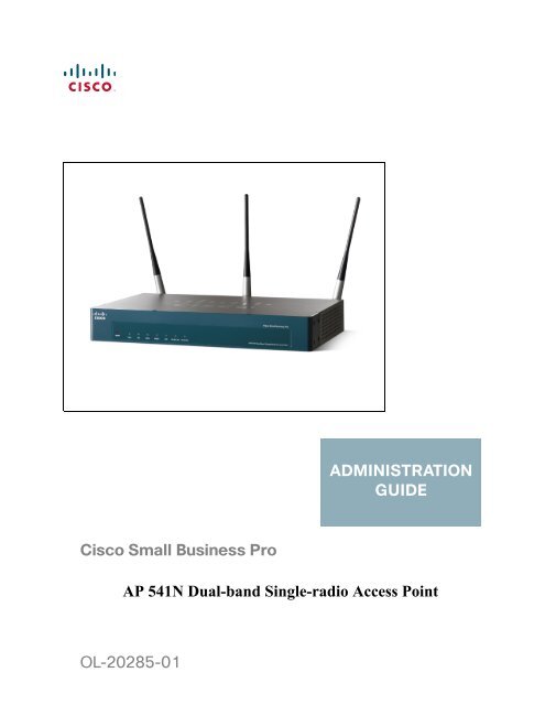
ADMINISTRATIONGUIDE<strong>Cisco</strong> Small Business ProAP 541N <strong>Dual</strong>-<strong>band</strong> <strong>Single</strong>-<strong>radio</strong> <strong>Access</strong> <strong>Point</strong>OL-20285-01
ContentsPreface 3Audience 3Document Conventions 3Online Help, Supported Browsers, and Limitations 5Chapter 1: Getting Started 6Administrator Computer Requirements 7<strong>Administration</strong> PC IP Address 8Connecting the <strong>Access</strong> <strong>Point</strong> to a PC 8Connect the <strong>Access</strong> <strong>Point</strong> to an <strong>Administration</strong> PC 9Connecting the <strong>Access</strong> <strong>Point</strong> to the PC by using a Direct Cable Connection9Connecting the <strong>Access</strong> <strong>Point</strong> to the PC through a Network Connection 10Launching the <strong>Access</strong> <strong>Point</strong> Configuration Utility 11Display the Configuration Utility By Using the Default IP Address 11Display the Configuration Utility by Using <strong>Cisco</strong> Configuration Assistant 2.1 orhigher 14Display the Configuration Utility by Using Another IP Address 16Troubleshooting Your Connection 18Using the Ping Command to Test the Connection 18Possible Cause of Failure 18Resetting the Device by using the Reset Button 19Configuring the <strong>Access</strong> <strong>Point</strong> by using the Getting Started Page 20<strong>Access</strong> <strong>Point</strong> Configuration 20<strong>Access</strong> <strong>Point</strong> Management Page 21Wireless Configuration Page 21Wireless Client Requirements 21Verifying the Installation 23Configuring Security on the Wireless <strong>Access</strong> <strong>Point</strong> 24Chapter 2: Status 26Device Information 27<strong>Cisco</strong> AP 541N <strong>Dual</strong>-<strong>band</strong> <strong>Single</strong>-<strong>radio</strong> <strong>Access</strong> <strong>Point</strong> Quick Start Guidei
ContentsNetwork Interfaces 28Wired Settings 29Wireless Settings 29Traffic Statistics 29Associated Clients 32Link Integrity Monitoring 34Rogue AP Detection 34Save or Import a List of Known <strong>Access</strong> <strong>Point</strong>s 39Chapter 3: Setup 40LAN Settings 40Configuring 802.1X Authentication 43Enabling the Network Time Protocol 46Chapter 4: Wireless 52Modifying Wireless Radio Settings 52Modifying Virtual <strong>Access</strong> <strong>Point</strong> Settings 55Security (Mode) 63Client Connection Control 76Configuring a MAC Filter and Station List on the <strong>Access</strong> <strong>Point</strong> 76Configuring MAC Authentication on the RADIUS Server 79Modifying Advanced Settings 79Configuring the Wireless Distribution System 91WEP on WDS Links 94WPA/PSK on WDS Links 95Bandwidth Utilization 96Configuring Quality of Service (QoS) 97Chapter 5: SNMP 104Configuring SNMP on the <strong>Access</strong> <strong>Point</strong> 104Configuring SNMP Views 108<strong>Cisco</strong> AP 541N <strong>Dual</strong>-<strong>band</strong> <strong>Single</strong>-<strong>radio</strong> <strong>Access</strong> <strong>Point</strong> Quick Start Guideii
ContentsConfiguring SNMP Groups 110Configuring SNMP Users 113SNMP Targets 115Chapter 6: <strong>Administration</strong> 118Administrator 118<strong>Access</strong> <strong>Point</strong> Configuration 120Resetting the <strong>Access</strong> <strong>Point</strong> to the Factory Default Configuration 121Saving the Current Configuration to a Backup File 121Saving the Current Configuration by using TFTP 121Saving the Current Configuration by using HTTP 122Restoring the Configuration from a Previously Saved File 122Restoring the Current Configuration by using TFTP 122Restoring the Current Configuration by Using HTTP 123Rebooting the <strong>Access</strong> <strong>Point</strong> 124Software Upgrade 124Upgrading the Software by using TFTP 124Upgrading the Software by Using HTTP 126Event Logs 127Configuring Persistent Logging Options 128Configuring the Log Relay Host for Kernel Messages 130Enabling or Disabling the Log Relay Host on the Events Page 131Configuring the Web Server Settings 132Creating an <strong>Administration</strong> <strong>Access</strong> Control List 134Chapter 7: Clustering Multiple <strong>Access</strong> <strong>Point</strong>s 136Managing <strong>Access</strong> <strong>Point</strong>s in the Cluster 136Clustering <strong>Single</strong> and <strong>Dual</strong> Radio <strong>Access</strong> <strong>Point</strong>s 137Viewing and Configuring Cluster Members 137Removing an <strong>Access</strong> <strong>Point</strong> from the Cluster 140Adding an <strong>Access</strong> <strong>Point</strong> to a Cluster 140Navigating to Configuration Information for a Specific <strong>Access</strong> <strong>Point</strong> 141<strong>Cisco</strong> AP 541N <strong>Dual</strong>-<strong>band</strong> <strong>Single</strong>-<strong>radio</strong> <strong>Access</strong> <strong>Point</strong> Quick Start Guideiii
ContentsNavigating to an <strong>Access</strong> <strong>Point</strong> by Using its IP Address in a URL 141Managing Cluster Sessions 142Sorting Session Information 144Configuring and Viewing Channel Management Settings 145Stopping/Starting Automatic Channel Assignment 146Viewing Current Channel Assignments and Setting Locks 147Viewing the Last Proposed Set of Changes 148Configuring Advanced Settings 149Viewing Wireless Neighborhood Information 150Viewing Details for a Cluster Member 154Chapter 8: Configuration Examples 156Configuring a VAP 157VAP Configuration from the Web Interface 158VAP Configuration Using SNMP 159Configuring Wireless Radio Settings 160Wireless Radio Configuration from the Web Interface 160Wireless Radio Configuration Using SNMP 162Configuring the Wireless Distribution System 162WDS Configuration from the Web Interface 163WDS Configuration Using SNMP 164Clustering <strong>Access</strong> <strong>Point</strong>s 165Clustering APs by Using the Web Interface 165Clustering <strong>Access</strong> <strong>Point</strong>s by Using SNMP 167Appendix A:Default Settings 168Appendix B:Where to Go From Here 172<strong>Cisco</strong> AP 541N <strong>Dual</strong>-<strong>band</strong> <strong>Single</strong>-<strong>radio</strong> <strong>Access</strong> <strong>Point</strong> Quick Start Guideiv
PrefacePrefaceThis guide describes setup, configuration, administration and maintenance for the<strong>Cisco</strong> ® AP 541N <strong>Dual</strong>-<strong>band</strong> <strong>Single</strong>-<strong>radio</strong> <strong>Access</strong> <strong>Point</strong> on a wireless network.AudienceThis guide is intended for System Administrators that are responsible forconfiguring and operating a network by using <strong>Cisco</strong> softwareTo obtain the greatest benefit from this guide, you should also have basicknowledge of Ethernet and wireless networking concepts.Document ConventionsThis section describes the conventions this document uses.NOTEA note provides more information about a feature or technology and crossreferencesto related topics.!CAUTION A caution provides information about critical aspects of access point configuration,combinations of settings, events, or procedures that can adversely affect networkconnectivity, security, and so forth.<strong>AP541N</strong> <strong>Dual</strong>-<strong>band</strong> <strong>Single</strong>-<strong>radio</strong> <strong>Access</strong> <strong>Point</strong> <strong>Administration</strong> Guide 3
PrefaceTable 1 describes the typographical conventions used in this guide.Table 1Typographical ConventionsSymbol Example DescriptionBoldBlue Textcourier fontcourier fontitalics Anglebrackets[ ] Squarebrackets[< >] Anglebrackets withinsquarebracketsClick Apply to saveyour settings.See DocumentConventions, page3.WLAN-AP# shownetworkvalue[value][]Menu titles, page names, and buttonnamesHyperlinked text.Screen text, file names, commands,user-typed command-line entriesCommand parameter, which might be avariable or fixed value.Indicates a parameter is a variable. Youmust enter a value in place of thebrackets and text inside them.Indicates an optional fixed parameter.Indicates an optional variable.{} curly braces {choice1 |choice2}| Vertical bars choice1 |choice2Indicates that you must select aparameter from the list of choices.Separates the mutually exclusivechoices.[{}] Braceswithin squarebrackets[{choice1 |choice2}]Indicate a choice within an optionalelement.<strong>AP541N</strong> <strong>Dual</strong>-<strong>band</strong> <strong>Single</strong>-<strong>radio</strong> <strong>Access</strong> <strong>Point</strong> <strong>Administration</strong> Guide 4
PrefaceOnline Help, Supported Browsers, and LimitationsOnline help for the <strong>Access</strong> <strong>Point</strong> Configuration Utility pages provides informationabout all fields and features available from the <strong>Access</strong> <strong>Point</strong> Configuration Utility.The information in the online help is a subset of the information available in the<strong>AP541N</strong> <strong>Dual</strong>-<strong>band</strong> <strong>Single</strong>-<strong>radio</strong> <strong>Access</strong> <strong>Point</strong> <strong>Administration</strong> Guide.Online help information corresponds to each page on the <strong>Access</strong> <strong>Point</strong>Configuration Utility.For information about the settings on the current page, click the Help link on theright side of a page.<strong>AP541N</strong> <strong>Dual</strong>-<strong>band</strong> <strong>Single</strong>-<strong>radio</strong> <strong>Access</strong> <strong>Point</strong> <strong>Administration</strong> Guide 5
1Getting StartedThe <strong>Cisco</strong> <strong>Access</strong> <strong>Point</strong> provides continuous, high-speed access betweenwireless devices and Ethernet devices. It is an advanced, standards-basedsolution for wireless networking in businesses of any size. The access pointenables wireless local area network (WLAN) deployment while providing state-ofthe-artwireless networking features.The access point operates in Standalone Mode. In Standalone Mode, the accesspoint acts as an individual access point in the network, and you manage it by usingthe <strong>Access</strong> <strong>Point</strong> Configuration Utility, or SNMP.This document describes how to perform the setup, management, andmaintenance of the access point in Standalone Mode. Before you power on a newaccess point, review the following sections to check required hardware andsoftware components, client configurations, and compatibility issues. Make sureyou have everything you need for a successful launch and test of your new orextended wireless network.This chapter contains the following topics:• Administrator Computer Requirements• Connecting the <strong>Access</strong> <strong>Point</strong> to a PC• Troubleshooting Your Connection• Configuring the <strong>Access</strong> <strong>Point</strong> by using the Getting Started Page• Verifying the Installation• Configuring Security on the Wireless <strong>Access</strong> <strong>Point</strong>To manage the access point by using the Web interface, the access point needsan IP address. If you use VLANs or IEEE 802.1X Authentication (port security) onyour network, you might need to configure additional settings on the access pointbefore it can connect to the network.<strong>Cisco</strong> AP 541N <strong>Dual</strong>-<strong>band</strong> <strong>Single</strong>-<strong>radio</strong> <strong>Access</strong> <strong>Point</strong> Quick Start Guide 6
1Getting StartedAdministrator Computer RequirementsNOTEThe WLAN AP is not designed to function as a gateway to the Internet. To connectyour WLAN to other LANs or the Internet, you need a gateway device.Administrator Computer RequirementsTable 1 describes the minimum requirements for the personal computer for theinitial configuration and administration of the access point through a <strong>Access</strong> <strong>Point</strong>Configuration Utility.Table 1Requirements for ConfigurationRequired Softwareor ComponentEthernet Connectionto the <strong>Access</strong> <strong>Point</strong>Web Browser andOperating SystemDescriptionThe computer used to configure the access point mustbe connected to the access point by an Ethernet cable.The IP address must be on the same subnet as theaccess point. The subnet mask must match the subnetmask of the access point. The <strong>Administration</strong> PC IPAddress section describes the procedure for changingthese parameters on a PC running Windows.The following Web browsers can be used to displaythe access point Configuration Utility Web pages:• Microsoft ® Internet Explorer ® version 6.x or 7.x(with up-to-date patch level for either majorversion) and Mozilla Firefox 3.x on MicrosoftWindows ® XP or Microsoft Windows 2000• Mozilla Firefox 3.x on Redhat ® Linux ® version 2.4or laterThe Web browser must have JavaScript enabled tosupport the interactive features of the ConfigurationUtility interface.Security SettingsEnsure that security is disabled on the wireless clientused initially to configure the access point. Once thedevice has been configured, security can be enabled.7 <strong>Cisco</strong> AP 541N <strong>Dual</strong>-<strong>band</strong> <strong>Single</strong>-<strong>radio</strong> <strong>Access</strong> <strong>Point</strong> Quick Start Guide
Getting StartedConnecting the <strong>Access</strong> <strong>Point</strong> to a PC1<strong>Administration</strong> PC IP AddressWe recommend that if you are starting from the default configuration or this is thefirst time the device will be configured that you configure the device before youdeploy it in the network by using the access point default static IP address(192.168.10.10). To do so, the PC IP address must be on the same subnet as theaccess point.Verify that your PC IP address is set to an address on the same subnet as theaccess point:STEP 1STEP 2STEP 3STEP 4STEP 5From the Windows Start menu, choose Settings > Control Panel.On the Control Panel dialog box, click Network.In the Network dialog box select TCP/IP for your PC Ethernet card, then clickProperties.In the IP Address window, click Specify an IP address.In the IP Address field, enter an IP address that is in the same subnet as the accesspoint IP address. (The default access point IP address is 192.168.10.10. Thedefault subnet mask is 255.255.255.0.) For example, you can set the:PC IP address to 192.168.10.250PC IP subnet mask to 255.255.255.0STEP 6 In the Subnet Mask field, type 255.255.255.0.STEP 7STEP 8Click OK.If you are prompted to restart your PC, click Yes.Connecting the <strong>Access</strong> <strong>Point</strong> to a PCTo configure the access point, you can connect the access point directly to anadministration PC or through the network to an administration PC.If you are not using CCA to configure the access point, we recommend that you configurethe device before deploying it in the network by following the instructions in the “Connectthe <strong>Access</strong> <strong>Point</strong> to an <strong>Administration</strong> PC” section. Otherwise, follow the instructions inthe “Connecting the <strong>Access</strong> <strong>Point</strong> to the PC through a Network Connection”<strong>Cisco</strong> AP 541N <strong>Dual</strong>-<strong>band</strong> <strong>Single</strong>-<strong>radio</strong> <strong>Access</strong> <strong>Point</strong> Quick Start Guide 8
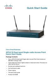
1Getting StartedConnecting the <strong>Access</strong> <strong>Point</strong> to a PCConnect the <strong>Access</strong> <strong>Point</strong> to an <strong>Administration</strong> PCYou can connect the access point to a administration PC directly or through thenetwork. We recommend that you connect the access point directly to the PCunless you are using CCA to configure the access point.Connecting the <strong>Access</strong> <strong>Point</strong> to the PC by using a Direct CableConnectionTo connect the access point to an administration PC, use a direct-cableconnection:STEP 1STEP 2Connect one end of an Ethernet straight-through or crossover cable to the networkport on the access point, as shown in Figure 1.Connect the other end of the cable to the Ethernet port on the PC.Figure 1Connecting the <strong>Access</strong> <strong>Point</strong> Using a Direct-Cable Connection192.168.10.10255.255.255.0192.168.10.250255.255.255.0195057If you use this method, you will need to reconfigure the cabling for subsequentstartup and deployment of the access point so that the access point is no longerconnected directly to the PC but instead is connected to the LAN (either by using ahub or a switch).STEP 3STEP 4STEP 5Connect the power adapter to the power port on the back of the access point.Plug the other end of the power cord into a power outlet.Configure the access point by following the instructions in the “Display theConfiguration Utility By Using the Default IP Address” section.9 <strong>Cisco</strong> AP 541N <strong>Dual</strong>-<strong>band</strong> <strong>Single</strong>-<strong>radio</strong> <strong>Access</strong> <strong>Point</strong> Quick Start Guide
Getting StartedConnecting the <strong>Access</strong> <strong>Point</strong> to a PC1Connecting the <strong>Access</strong> <strong>Point</strong> to the PC through a Network ConnectionTo connect the access point to an administration PC through the network:STEP 1STEP 2Connect one end of an Ethernet straight-through or crossover cable to the networkport on the access point, as shown in Figure 2.Connect the other end to the same hub or switch where your PC is connected.Figure 2Connecting the <strong>Access</strong> <strong>Point</strong> Using a LAN ConnectionThe hub or switch you use must permit broadcast signals from the access point toreach the other devices on the network.STEP 3If you are not using PoE, connect the power adapter to the power port on the backof the access point, then plug the other end of the power cord into a power outlet.<strong>Cisco</strong> AP 541N <strong>Dual</strong>-<strong>band</strong> <strong>Single</strong>-<strong>radio</strong> <strong>Access</strong> <strong>Point</strong> Quick Start Guide 10
1Getting StartedConnecting the <strong>Access</strong> <strong>Point</strong> to a PCLaunching the <strong>Access</strong> <strong>Point</strong> Configuration UtilityThis section contains information for the for launching the <strong>Access</strong> <strong>Point</strong>Configuration Utility:• Using the default static IP address of the switch. Follow the instructions in the“Display the Configuration Utility By Using the Default IP Address”section.• Using <strong>Cisco</strong> Configuration Assistant (CCA). Follow the instructions in the“Display the Configuration Utility by Using <strong>Cisco</strong> Configuration Assistant2.1 or higher” section.• Using the an IP address assigned to the switch through DHCP. Follow theinstructions in the “Display the Configuration Utility by Using Another IPAddress” section.Display the Configuration Utility By Using the Default IPAddressTo access the <strong>Access</strong> <strong>Point</strong> Configuration Utility, enter the default static IPaddress of the access point into a Web browser, do the following:STEP 1Enter the <strong>Cisco</strong> AP 541N default static IP address in the address bar and press Enter. Forexample, http://192.168.10.10.The Login window displays, as shown in Figure 3.11 <strong>Cisco</strong> AP 541N <strong>Dual</strong>-<strong>band</strong> <strong>Single</strong>-<strong>radio</strong> <strong>Access</strong> <strong>Point</strong> Quick Start Guide
Getting StartedConnecting the <strong>Access</strong> <strong>Point</strong> to a PC1Figure 3Login WindowSTEP 2Enter the login information:Username = ciscoDefault password cisco. (Passwords are case sensitive.)When you log in, the Getting Started page for the access point ConfigurationUtility is displayed, as shown in Figure 4.<strong>Cisco</strong> AP 541N <strong>Dual</strong>-<strong>band</strong> <strong>Single</strong>-<strong>radio</strong> <strong>Access</strong> <strong>Point</strong> Quick Start Guide 12
1Getting StartedConnecting the <strong>Access</strong> <strong>Point</strong> to a PCFigure 4Getting Started PageSTEP 3Update the <strong>Cisco</strong> AP 541N software with the latest version by clicking the SoftwareUpgrade link, as shown in Figure 4.Next, we recommend that you:• Change the password by clicking Change Administrator Password.• Configure the SSID and enable wireless security, by clicking ConfigureWireless Networks (SSIDs).• Enable the wireless <strong>radio</strong>, by clicking Enable Wireless Radio.• Assign a new static IP address to the access point if your network devicesare configured with static IP addresses, by clicking Set LAN IP Address.13 <strong>Cisco</strong> AP 541N <strong>Dual</strong>-<strong>band</strong> <strong>Single</strong>-<strong>radio</strong> <strong>Access</strong> <strong>Point</strong> Quick Start Guide
Getting StartedConnecting the <strong>Access</strong> <strong>Point</strong> to a PC1Display the Configuration Utility by Using<strong>Cisco</strong> Configuration Assistant 2.1 or higherUse <strong>Cisco</strong> Configuration Assistant 2.1 or higher (CCA) to configure the accesspoint when it is deployed in a <strong>Cisco</strong> Smart Business Communications System(SBCS) network with a UC520 or SR520.DHCP clientInternet195058This procedure assumes you are familiar with CCA. You can find additionalinformation about CCA at http://www.cisco.com/en/US/products/ps7287/tsd_products_support_series_home.htmlTo configure the access point by using CCA:STEP 1STEP 2STEP 3STEP 4STEP 5STEP 6Connect the Ethernet port on the access point to a switch port on a SBCS device.Power on the <strong>Cisco</strong> <strong>AP541N</strong>.Connect a PC with CCA installed to any access switch port on the UC520 orSR520.Create a new CCA site by entering a name and the IP address of the UC520 orSR520.Connect to the CCA site by using the appropriate login credentials.Click Window > Topology View.<strong>Cisco</strong> AP 541N <strong>Dual</strong>-<strong>band</strong> <strong>Single</strong>-<strong>radio</strong> <strong>Access</strong> <strong>Point</strong> Quick Start Guide 14
1Getting StartedConnecting the <strong>Access</strong> <strong>Point</strong> to a PCWhen you have connected to the CCA site and the devices have been discovered,the Topology Map includes the <strong>Cisco</strong> <strong>AP541N</strong>.NOTE Non-<strong>Cisco</strong> devices connected to the switch are not shown in the Topologymap.STEP 7STEP 8Right-click the access point to display the options: Configuration Utility,Properties, and Annotation.Click Configuration Utility.The <strong>Access</strong> <strong>Point</strong> Configuration Utility displays in a new window, as shown inFigure 4.Next, we recommend that you:• Change the password by clicking Change Administrator Password.• Configure the SSID and enable wireless security, by clicking ConfigureWireless Networks (SSIDs).• Enable the wireless <strong>radio</strong>, by clicking Enable Wireless Radio.• Assign a new static IP address to the access point if your network devicesare configured with static IP addresses, by clicking Set LAN IP Address.15 <strong>Cisco</strong> AP 541N <strong>Dual</strong>-<strong>band</strong> <strong>Single</strong>-<strong>radio</strong> <strong>Access</strong> <strong>Point</strong> Quick Start Guide
Getting StartedConnecting the <strong>Access</strong> <strong>Point</strong> to a PC1Display the Configuration Utility by Using Another IP AddressYou can display the <strong>Access</strong> <strong>Point</strong> Configuration Utility by using an IP addressassigned to the access point during a previous configuration or by a DHCP server.When you power on the access point, the built-in DHCP client searches for aDHCP server on the network to obtain an IP address and other networkinformation. If the access point does not find a DHCP server on the network, theaccess point uses its default static IP address (192.168.10.10) unless you haveassigned it a static IP address (and specified a static IP addressing policy) or untilthe access point successfully receives network information from a DHCP server.!CAUTION If the access point IP address is changed, either by a DHCP server or manually, yourlink to the access point will be lost and you must enter the new IP address to usethe <strong>Access</strong> <strong>Point</strong> Configuration Utility.To configure the access point by using an IP address other than the default staticIP address:STEP 1STEP 2Power on the <strong>Cisco</strong> <strong>AP541N</strong>.If you used a DHCP server on your network to automatically configure networkinformation for the access point, enter the IP address assigned to the access pointby the DHCP server into the Web browser.If you have access to the DHCP server on your network and know the MACaddress of your access point, you can view the new IP address associated withthe MAC address of the access point. Otherwise, we recommend that youdisconnect the access point from the network, reset it to the default configurationby using the procedure in the “Resetting the Device by using the Reset Button”section, and configuring the device by using the procedure in the “Display theConfiguration Utility By Using the Default IP Address” section.If you replaced the default static IP address with a new static IP address, enter thenew IP address of the access point into the Web browserThe Login window displays, as shown in Figure 3.STEP 3Enter the login information:Username is ciscoDefault password is cisco (passwords are case sensitive)<strong>Cisco</strong> AP 541N <strong>Dual</strong>-<strong>band</strong> <strong>Single</strong>-<strong>radio</strong> <strong>Access</strong> <strong>Point</strong> Quick Start Guide 16
1Getting StartedConnecting the <strong>Access</strong> <strong>Point</strong> to a PCWhen you log in, the Getting Started page for the access point ConfigurationUtility is displayed, as shown in Figure 4.STEP 4Update the <strong>Cisco</strong> AP 541N software with the latest version by clicking the SoftwareUpgrade link, as shown in Figure 4.Next, we recommend that you:• Change the password by clicking Change Administrator Password.• Configure the SSID and enable wireless security, by clicking ConfigureWireless Networks (SSIDs).• Enable the wireless <strong>radio</strong>, by clicking Enable Wireless Radio.• Assign a new static IP address to the access point if your network devicesare configured with static IP addresses, by clicking Set LAN IP Address.!CAUTION If you do not have a DHCP server on your internal network, and do not plan to useone, we recommend assigning a new static IP address so that if you bring upanother WLAN <strong>Cisco</strong> <strong>AP541N</strong> on the same network, the IP address for each accesspoint is unique. If the IP address is not unique, a conflict results causingunpredictable results.To change the connection type and assign a static IP address by using the <strong>Access</strong><strong>Point</strong> Configuration Utility, see LAN Settings, page 40.17 <strong>Cisco</strong> AP 541N <strong>Dual</strong>-<strong>band</strong> <strong>Single</strong>-<strong>radio</strong> <strong>Access</strong> <strong>Point</strong> Quick Start Guide
Getting StartedTroubleshooting Your Connection1Troubleshooting Your ConnectionIf you cannot display the login window, you can test the IP address by using theping command. If you do not know the IP address, you can configure the device byresetting the device to the factory defaults and accessing the <strong>Access</strong> <strong>Point</strong>Configuration Utility by using the factory default static IP address.Using the Ping Command to Test the ConnectionIf you cannot display the configuration utility, you can test the ability of the PC tocommunicate with the access point by using ping. To use ping on a PC runningWindows:STEP 1STEP 2STEP 3Verify that the <strong>Cisco</strong> AP 541N is powered on and the LEDs indicate theappropriate links.Open a command window by using Start > Run and enter cmd.At the Command window prompt enter ping and the access point IPaddress. For example ping 192.168.10.10 (the default static IP address of theaccess point).If successful, you should get a reply similar to the following:Pinging 192.168.10.10 with 32 bytes of data:Reply from 192.168.10.10: bytes=32 time
1Getting StartedTroubleshooting Your ConnectionDHCP is enabled on the <strong>Cisco</strong> AP 541N by default. When a DHCP server isenabled on your network and the access point is connected to the network, theDHCP server replaces the default static IP address with a DHCP server–assignedIP address. If this happens before you display the <strong>Access</strong> <strong>Point</strong> ConfigurationUtility window, you must use the assigned IP address to display the utility. If thishappens during configuration, the <strong>Access</strong> <strong>Point</strong> Configuration Utility will loseconnectivity.You can query the DHCP server for the new IP address or disconnect the accesspoint from the network and reset the device to use the static default access pointIP address by using the Resetting the <strong>Access</strong> <strong>Point</strong> to the Factory DefaultConfiguration, page 121 procedure.Resetting the Device by using the Reset ButtonTo use the Reset button to reboot or reset the access point, do the following:• To reboot the access point, press the Reset button. Do not hold it for morethan 10 seconds.• To restore the access point to the factory default settings:1. Disconnect the access point from the network or disable all DHCPservers on your network.2. With the power on, press-and-hold the Reset button for more than 10seconds.19 <strong>Cisco</strong> AP 541N <strong>Dual</strong>-<strong>band</strong> <strong>Single</strong>-<strong>radio</strong> <strong>Access</strong> <strong>Point</strong> Quick Start Guide
Getting StartedConfiguring the <strong>Access</strong> <strong>Point</strong> by using the Getting Started Page1Configuring the <strong>Access</strong> <strong>Point</strong> by using the Getting StartedPageFrom the Getting Started page, you can use the following links to quickly configureyour access point:• <strong>Access</strong> <strong>Point</strong> Configuration• <strong>Access</strong> <strong>Point</strong> Management Page• Wireless Configuration Page<strong>Access</strong> <strong>Point</strong> ConfigurationTo change the access point IP address, password, and VLAN configuration, do thefollowing:STEP 1STEP 2Click Change Administrator Password to provide a new administration passwordfor the access point. (The username is cisco and it cannot be changed. The defaultpassword is cisco.)If you do not have a DHCP server on the network and do not plan to use one, clickChange IP Address to change the connection type from DHCP to static IP and seta static IP address and subnet mask.NOTE We recommend that you assign a new static IP address. Otherwise, if youbring up another <strong>Cisco</strong> AP 541N on the same network, the IP address foreach access point will not be unique; duplicating an IP address on a networkwill create a conflict.Also, if you change the static IP address, you will lose connectivity. Toreestablish connectivity, enter the new IP address into your Web browserand log into the Configuration Utility.To change the connection type and assign a static IP address, see LANSettings, page 40.<strong>Cisco</strong> AP 541N <strong>Dual</strong>-<strong>band</strong> <strong>Single</strong>-<strong>radio</strong> <strong>Access</strong> <strong>Point</strong> Quick Start Guide 20
1Getting StartedWireless Client RequirementsSTEP 3If your network uses VLANs, you might need to configure the management VLANID or untagged VLAN ID on the access point for it to work with your network.For information about how to configure VLAN information, see LAN Settings, page40.STEP 4If your network uses Dynamic WEP port security for network access control, youmust configure the 802.1X supplicant information on the access point. Forinformation about how to configure the 802.1X user name and password, seeConfiguring 802.1X Authentication, page 43.<strong>Access</strong> <strong>Point</strong> Management PageClick System Information to view the device information. For more information, seeDevice Information, page 27.As new versions of the <strong>Access</strong> <strong>Point</strong> software become available, you can upgradethe software on your devices to take advantage of new features andenhancements. For more information, see Software Upgrade, page 124.For information on how to backup and restore the configuration, go to <strong>Access</strong><strong>Point</strong> Configuration, page 120.Wireless Configuration PageFor information about the wireless <strong>radio</strong> settings, see Configuring Wireless RadioSettings, page 160.To configure the SSID, Guest <strong>Access</strong>, and Security Configuration, see ModifyingVirtual <strong>Access</strong> <strong>Point</strong> Settings, page 55.Wireless Client RequirementsThe access point provides wireless access to any client with a properlyconfigured Wi-Fi client adapter for the 802.11 mode in which the access point isrunning. The access point supports multiple client operating systems. Clients canbe laptop or desktop computers, personal digital assistants (PDAs), or any otherhand-held, portable or stationary device equipped with a Wi-Fi adapter andsupporting drivers.21 <strong>Cisco</strong> AP 541N <strong>Dual</strong>-<strong>band</strong> <strong>Single</strong>-<strong>radio</strong> <strong>Access</strong> <strong>Point</strong> Quick Start Guide
Getting StartedWireless Client Requirements1To connect to the access point, wireless clients need the software and hardwaredescribed in Table 2.Table 2Requirements for Wireless ClientsRequired ComponentWi-Fi Client AdapterWireless ClientSoftwareClient SecuritySettingsDescriptionPortable or built-in Wi-Fi client adapter that supportsone or more of the IEEE 802.11 modes in which youplan to run the access point. (IEEE 802.11a, 802.11b,802.11g, and 802.11n modes are supported.)Client software, such as Microsoft WindowsSupplicant, configured to associate with the accesspoint.Security should be disabled on the client used to doinitial configuration of the access point.If the Security mode on the access point is set toanything other than plain text, wireless clients musthave a profile set to the same authentication modeused by the access point and provide a valid usernameand password, certificate, or user identity required bythe authentication server. Security modes are StaticWEP, IEEE 802.1X, WPA with RADIUS server, and WPA-PSK.For information about configuring security on theaccess point, see Configuring the WirelessDistribution System, page 91.<strong>Cisco</strong> AP 541N <strong>Dual</strong>-<strong>band</strong> <strong>Single</strong>-<strong>radio</strong> <strong>Access</strong> <strong>Point</strong> Quick Start Guide 22
1Getting StartedVerifying the InstallationVerifying the InstallationMake sure the access point is connected to the LAN and associating with wirelessclients on the network. Once you have tested the basics of your wireless network,you can enable more security and fine-tune the access point by modifying theadvanced configuration features.STEP 1Connect the access point to the LAN.If you configured the access point by using a direct cable connection from yourcomputer to the access point, do the following:a. Disconnect the cable from the computer and the access point.b. Mount the access point in the desired location.c. Connect an Ethernet cable from the access point to the LAN.d. Power on the access point.e. Connect your computer to the LAN by using an Ethernet cable or a wirelesscard.If you configured the access point and an administrator PC by connecting both toa network hub or switch, your access point is already connected to the LAN. Thenext step is to test some wireless clients.STEP 2Test the access point by trying to detect it and associate with it from a wirelessclient. For information about requirements for the client devices, see WirelessClient Requirements, page 21.NOTE The access point is not designed for multiple, simultaneous configurationchanges. If more than one administrator is logged onto the ConfigurationUtility and is making changes to the configuration, there is no guarantee thatall configuration changes specified by multiple users will be applied.23 <strong>Cisco</strong> AP 541N <strong>Dual</strong>-<strong>band</strong> <strong>Single</strong>-<strong>radio</strong> <strong>Access</strong> <strong>Point</strong> Quick Start Guide
Getting StartedConfiguring Security on the Wireless <strong>Access</strong> <strong>Point</strong>1!CAUTION By default, no security is in place on the access point, so any wireless client canassociate with it and access your LAN, including unauthorized devices. Animportant next step is to configure security. Continue with Configuring Security onthe Wireless <strong>Access</strong> <strong>Point</strong>, page 24 for more information.Configuring Security on the Wireless <strong>Access</strong> <strong>Point</strong>You configure secure wireless client access by configuring security for eachvirtual access point (VAP) that you enable. You can configure up to 16 VAPs perwireless <strong>radio</strong> that simulate multiple access points in one physical access point.For each VAP, you can configure a unique security mode to control wireless clientaccess.Each wireless <strong>radio</strong> has 16 VAPs, with VAP IDs from 0-15. VAP 0, VAP 1, and VAP 2have different default settings than VAPs 3-15. By default, VAP 0, VAP 1, and VAP 2are enabled.VAP0 has the following default settings:• VLAN ID: 1• SSID: cisco-data• Broadcast SSID: Enabled• Security: None• MAC Authentication Type: Disabled• Station Isolation: Disabled• HTTP Redirect: DisableVAP1 has the following default settings:• VLAN ID: 100• SSID: cisco-voice• Broadcast SSID: Enabled• Security: None• MAC Authentication Type: Disabled<strong>Cisco</strong> AP 541N <strong>Dual</strong>-<strong>band</strong> <strong>Single</strong>-<strong>radio</strong> <strong>Access</strong> <strong>Point</strong> Quick Start Guide 24
1Getting StartedConfiguring Security on the Wireless <strong>Access</strong> <strong>Point</strong>• Station Isolation: Disabled• HTTP Redirect: DisableVAP2 has the following default settings:• VLAN ID: 1• SSID: cisco-scan• Broadcast SSID: Enabled• Security: WPA Personal• WPA Versions: WPA2• Cipher Suites: CCMP (AES)• Key: intermec• MAC Authentication Type: Disabled• Station Isolation: Disabled• HTTP Redirect: DisableVAP3-15 are disabeld by default, but when they are enabled they will have thefollowing default settings:• VLAN ID: 1• SSID: Virtual <strong>Access</strong> <strong>Point</strong> x ( where x is the VAP ID)• Broadcast SSID: Enabled• Security: None• MAC Authentication Type: Disabled• Station Isolation: Disabled• HTTP Redirect: DisableTo prevent unauthorized access to the access point, we recommend that youselect and configure a security option other than None for the default VAP and foreach VAP that you enable.For information about how to configure the security settings on each VAP, seeConfiguring the Wireless Distribution System, page 91.25 <strong>Cisco</strong> AP 541N <strong>Dual</strong>-<strong>band</strong> <strong>Single</strong>-<strong>radio</strong> <strong>Access</strong> <strong>Point</strong> Quick Start Guide
2StatusThe Status page provides information on the following:• Device Information• Network Interfaces• Traffic Statistics• Associated Clients• Rogue AP Detection<strong>Cisco</strong> AP 541N <strong>Dual</strong>-<strong>band</strong> <strong>Single</strong>-<strong>radio</strong> <strong>Access</strong> <strong>Point</strong> Quick Start Guide 26
2StatusDevice InformationDevice InformationFrom the Device Information page, you can view hardware and productinformation.Figure 5Device InformationTable 3 describes the fields shown on the Device Information page.Table 3FieldDevice Information PageDescriptionProduct IdentifierHardware VersionSoftware VersionSerial NumberDevice NameDevice DescriptionIdentifies the AP hardware model.Identifies the AP hardware version.Shows version information for the software installed on theAP. As new versions of the WLAN AP software becomeavailable, you can upgrade the software.Shows the AP serial number.Generic name to identify the type of hardware.Provides information about the product hardware.27 <strong>Cisco</strong> AP 541N <strong>Dual</strong>-<strong>band</strong> <strong>Single</strong>-<strong>radio</strong> <strong>Access</strong> <strong>Point</strong> Quick Start Guide
2Table 3FieldDevice Information PageDescriptionSystem UptimeThe amount of time that the AP has been operational sinceits last power-up/reboot.Network InterfacesThe Network Interface Status window displays the current Wired Settings andthe Wireless Settings of the access point. Click Refresh to refresh the page.Figure 6Interface Status<strong>Cisco</strong> AP 541N <strong>Dual</strong>-<strong>band</strong> <strong>Single</strong>-<strong>radio</strong> <strong>Access</strong> <strong>Point</strong> Quick Start Guide 28
2StatusTraffic StatisticsWired SettingsThe Wired Settings include the MAC address, management VLAN ID, IP address,subnet mask, and DNS information. To change any of these settings, click Edit tobe redirected to the Setup > LAN Settings page.For information about configuring these settings, see LAN Settings, page 40.Wireless SettingsThe Wireless Settings section indicates the status of the wireless <strong>radio</strong>, andincludes the Radio Mode and Channel. The Wireless Settings section also showsthe MAC address (read-only) associated with each wireless <strong>radio</strong> interface.To change the Radio Mode or Channel settings, click Edit. You are redirected to theWireless > Radio Settings page.For information about configuring these settings, see Modifying Wireless RadioSettings, page 52 and Modifying Advanced Settings, page 79.Traffic StatisticsThe Traffic Statistics page provides basic information about the access point, areal-time display of the transmit and receive statistics for the Ethernet interface,and VAP (Virtual <strong>Access</strong> <strong>Point</strong>) statistics. The transmit and receive statistics aretotals since the access point was last started. If you reboot the access point, thesefigures indicate transmit and receive totals since the reboot.To view transmit and receive statistics for the access point, click the TrafficStatistics tab. Click Refresh to refresh the page.29 <strong>Cisco</strong> AP 541N <strong>Dual</strong>-<strong>band</strong> <strong>Single</strong>-<strong>radio</strong> <strong>Access</strong> <strong>Point</strong> Quick Start Guide
StatusTraffic Statistics2Figure 7Viewing Traffic Statistics<strong>Cisco</strong> AP 541N <strong>Dual</strong>-<strong>band</strong> <strong>Single</strong>-<strong>radio</strong> <strong>Access</strong> <strong>Point</strong> Quick Start Guide 30
2StatusTraffic StatisticsTable 4FieldTraffic Statistics DescriptionDescriptionNetwork InterfacesStatusMAC AddressVLAN IDName (SSID)The name of the Ethernet or VAP interfaces.Shows whether the interface is up or down.MAC address for the specified interface. Each VAPinterface has a unique MAC address.A virtual LAN (VLAN) ID is used to establish multiplenetworks on the same access point. The VLAN ID isconfigured on the Wireless > VAP tab. (See BandwidthUtilization, page 96.)The network name, also known as the SSID, is analphanumeric key that uniquely identifies a VAP. Thename (SSID) is configured on the VAP tab. (SeeBandwidth Utilization, page 96.) NA means either thatthe entry is not applicable or is not supported.Transmit and Receive InformationTotal PacketsTotal BytesTotal Dropped PacketsTotal Dropped BytesErrorsIndicates total packets sent (in Transmit table) orreceived (in Received table) on that interface.Indicates total bytes sent (in Transmit table) orreceived (in Received table) on that interface.Indicates total number of packets sent (in Transmittable) or received (in Received table) on that interfacethat were dropped. NA means that the drop and errorcounters for the VAP interfaces and the WDSinterfaces are not supported.Indicates total number of bytes sent (in Transmit table)or received (in Received table) on that interface thatwere dropped. NA means that the drop and errorcounters for the VAP interfaces and the WDSinterfaces are not supported.Displays the total number of transmit and receiveerrors detected by the AP. NA means that the drop anderror counters for the VAP interfaces and the WDSinterfaces are not supported.31 <strong>Cisco</strong> AP 541N <strong>Dual</strong>-<strong>band</strong> <strong>Single</strong>-<strong>radio</strong> <strong>Access</strong> <strong>Point</strong> Quick Start Guide
StatusAssociated Clients2Associated ClientsTo view the client stations associated with the access point, click the AssociatedClients tab.Figure 8Viewing Client Association InformationThe associated stations are displayed along with information about packet traffictransmitted and received for each station. Click Refresh to refresh the page.Table 5 describes the fields on the Associated Clients page.Table 5FieldNetworkStationAssociated Clients Field DescriptionsDescriptionShows which VAP the client is associated with. Forexample, an entry of wlan0vap2 means the client isassociated with Wireless Radio 1, VAP 2.Shows the MAC address of the associated wirelessclient.<strong>Cisco</strong> AP 541N <strong>Dual</strong>-<strong>band</strong> <strong>Single</strong>-<strong>radio</strong> <strong>Access</strong> <strong>Point</strong> Quick Start Guide 32
2StatusAssociated ClientsTable 5FieldStatusAssociated Clients Field DescriptionsDescriptionThe Authenticated and Associated Status shows theunderlying IEEE 802.11 authentication and associationstatus that is present no matter which type of security theclient uses to connect to the access point. This statusdoes not show the IEEE 802.1X authentication orassociation status.Some points to keep in mind with regard to this field are:• If the AP security mode is None or Static WEP, theauthentication and association status of clientsshowing on the Client Associations tab will be inline with what is expected; that is, if a client showsas authenticated to the access point, it will be ableto transmit and receive data. (This is becauseStatic WEP uses only IEEE 802.11 authentication.)• If the access point uses IEEE 802.1X or WPAsecurity, however, it is possible for a clientassociation to show on this tab as authenticated(by using IEEE 802.11 security) but actually not beauthenticated to the access point by using thesecond layer of security.From StationTo StationShows the number of packets and bytes received fromthe wireless client and the number of packets and bytesthat were dropped after being received.Shows the number of packets and bytes transmittedfrom the access point to the wireless client and thenumber of packets and bytes that were dropped upontransmission.33 <strong>Cisco</strong> AP 541N <strong>Dual</strong>-<strong>band</strong> <strong>Single</strong>-<strong>radio</strong> <strong>Access</strong> <strong>Point</strong> Quick Start Guide
StatusRogue AP Detection2Link Integrity MonitoringThe access point provides link integrity monitoring to continually verify itsconnection to each associated client. To do this, the access point sends datapackets to clients every few seconds when no other traffic is passing. This allowsthe access point to detect when a client goes out of range, even during periodswhen no normal traffic is exchanged. The client connection drops off the list within300 seconds if these data packets are not acknowledged, even if nodisassociation message is received.Rogue AP DetectionA Rogue AP is an access point that has been installed on a secure network withoutauthorization from a system administrator. Rogue access points pose a securitythreat because anyone with access to the premises can ignorantly or maliciouslyinstall a wireless access point that might allow unauthorized parties to access thenetwork.The Rogue AP Detection page displays information about all access pointsdetected by the <strong>Cisco</strong> AP 541N in the vicinity of the network. If the access pointlisted as a rogue is actually a legitimate access point, you can add it to the KnownAP List. Click Refresh to refresh the page.NOTEThe Detected Rouge AP List and Known AP List provide information. The <strong>Cisco</strong>AP 541N does not have any control over the access points on the lists and cannotapply any security policies to access points detected through the RF scan.<strong>Cisco</strong> AP 541N <strong>Dual</strong>-<strong>band</strong> <strong>Single</strong>-<strong>radio</strong> <strong>Access</strong> <strong>Point</strong> Quick Start Guide 34
2StatusRogue AP DetectionFigure 9Viewing Neighboring <strong>Access</strong> <strong>Point</strong>sYou must enable the access point detection to collect information about otheraccess points within range. Table 6 describes the information provided onneighboring access points.Table 6FieldNeighboring <strong>Access</strong> <strong>Point</strong> InformationDescriptionAP DetectionTo enable neighbor access point detection and collectinformation about neighbor access points, click Enabled.(default)To disable neighbor access point detection, click Disabled.To save the setting, click Apply.35 <strong>Cisco</strong> AP 541N <strong>Dual</strong>-<strong>band</strong> <strong>Single</strong>-<strong>radio</strong> <strong>Access</strong> <strong>Point</strong> Quick Start Guide
StatusRogue AP Detection2Table 6FieldActionNeighboring <strong>Access</strong> <strong>Point</strong> InformationDescriptionIf an access point is in the Detected Rogue AP List, you canclick Grant to move the access point from the DetectedRogue AP List to the Known AP List.If an access point is in the Known AP List, click the Deletebutton to move the access point from the Known AP List tothe Detected Rogue AP List.NOTE: The Detected Rouge AP List and Known AP Listprovide information only; the <strong>Cisco</strong> AP 541N does not haveany control over the access points on the list and cannotapply any security policies to access points detectedthrough the RF scan.MACBeacon Int.Shows the MAC address of the detected access point.Shows the Beacon interval of another access point.Beacon frames are transmitted by an access point at regularintervals to announce their existence on the wirelessnetwork. The default behavior is to send a beacon frameonce every 100 milliseconds (or 10 per second).The Beacon Interval for your access point is set on theWireless > Advanced Settings page. (See ModifyingAdvanced Settings, page 79.)TypeIndicates the type of device:• AP indicates the detected device is an access pointthat supports the IEEE 802.11 Wireless NetworkingFramework in Infrastructure Mode.• Ad hoc designation indicates a neighboring stationrunning in ad hoc mode. Stations set to ad hoc modecommunicate with each other directly, without the useof a traditional access point. Ad-hoc mode is an IEEE802.11 Wireless Networking Framework also referredto as peer-to-peer mode or an Independent BasicService Set (IBSS).<strong>Cisco</strong> AP 541N <strong>Dual</strong>-<strong>band</strong> <strong>Single</strong>-<strong>radio</strong> <strong>Access</strong> <strong>Point</strong> Quick Start Guide 36
2StatusRogue AP DetectionTable 6FieldSSIDNeighboring <strong>Access</strong> <strong>Point</strong> InformationDescriptionThe Service Set Identifier (SSID) for another, detectedaccess point.The SSID is an alphanumeric string of up to 32 charactersthat uniquely identifies a wireless local area network. It isalso referred to as the Network Name.The SSID is set on the Virtual <strong>Access</strong> <strong>Point</strong> tab. (SeeBandwidth Utilization, page 96.)PrivacyIndicates whether there is any security on the neighboringaccess point.• Off indicates that the Security mode on theneighboring access point is set to None (no security).• On indicates that the neighboring access point hassome security in place.Security is configured on the access point from the Virtual<strong>Access</strong> <strong>Point</strong> page.WPABandIndicates whether WPA security is on or off for the detectedaccess point.This indicates the IEEE 802.11 mode being used on thedetected access point. (For example, IEEE 802.11a, IEEE802.11b, IEEE 802.11g.)The number shown indicates the mode according to thefollowing map:• 2.4 indicates IEEE 802.11b, 802.11g, or 802.11n mode(or a combination of the modes)• 5 indicates IEEE 802.11a mode, 802.11n mode, or acombination of modes.37 <strong>Cisco</strong> AP 541N <strong>Dual</strong>-<strong>band</strong> <strong>Single</strong>-<strong>radio</strong> <strong>Access</strong> <strong>Point</strong> Quick Start Guide
StatusRogue AP Detection2Table 6FieldChannelNeighboring <strong>Access</strong> <strong>Point</strong> InformationDescriptionShows the Channel on which the detected access point isbroadcasting.The channel defines the portion of the wireless <strong>radio</strong>spectrum that the wireless <strong>radio</strong> uses for transmitting andreceiving.The channel for your access point is set in Wireless >Advanced Settings. (See Modifying Advanced Settings,page 79.)RateShows the rate (in megabits per second) at which thedetected access point is currently transmitting.The current rate is always one of the rates shown inSupported Rates.SignalBeaconsLast BeaconRatesIndicates the strength of the wireless <strong>radio</strong> signal emittingfrom the detected access point. If you hover the mousepointer over the bars, a number appears and shows thestrength in decibels (dB).Shows the total number of beacons received from thedetected access point since it was first discovered.Shows the date and time of the last beacon received fromthe detected access point.Shows supported and basic (advertised) rate sets for thedetected access point. Rates are shown in megabits persecond (Mbps).All Supported Rates are listed, with Basic Rates shown inbold.Rate sets are configured on the Wireless > AdvancedSettings page. (See Modifying Advanced Settings, page79.)<strong>Cisco</strong> AP 541N <strong>Dual</strong>-<strong>band</strong> <strong>Single</strong>-<strong>radio</strong> <strong>Access</strong> <strong>Point</strong> Quick Start Guide 38
2StatusRogue AP DetectionSave or Import a List of Known <strong>Access</strong> <strong>Point</strong>sTo save the Known AP List to a file, click Save. The list contains the MACaddresses of all access points that have been added to the Known AP List. Bydefault, the filename is Rogue2.cfg. You can use a text editor or Web browser toopen the file and view its contents.Use the Import feature to import a list of known access points from a saved list.The list might be from another <strong>Cisco</strong> access point or created from a text file. If theMAC address of an access point appears in the Known AP List, it will not beshown as a rogue.The file you import must be a plain-text file with a .txt or .cfg extension. Entries inthe file are MAC addresses in hexadecimal format with each octet separated bycolons, for example 00:11:22:33:44:55. Separate the entries with a single space.For the access point to accept the file, it must contain only MAC addresses.To import an access point list from a file, do the following:STEP 1Choose whether to replace the existing Known AP List or add the entries in theimported file to the Known AP List.• Select the Replace <strong>radio</strong> button to import the list and replace the entirecontents of the Known AP List.• Select the Merge <strong>radio</strong> button to import the list and add the access pointsin the imported file to the access points currently displayed in the KnownAP List.STEP 2STEP 3Click Browse and choose the file to import.Click Import.Once the import is complete, the screen refreshes and the MAC addresses ofthe access points listed in the imported file appear in the Known AP List.39 <strong>Cisco</strong> AP 541N <strong>Dual</strong>-<strong>band</strong> <strong>Single</strong>-<strong>radio</strong> <strong>Access</strong> <strong>Point</strong> Quick Start Guide
3SetupLAN SettingsThe default wired LAN interface settings, including the default DHCP and VLANparameters, might not work correctly for your network.By default, the DHCP client on the access point broadcasts requests for networkinformation. To use a static IP address, you must disable the DHCP client andmanually configure the IP address and other network information.The access point default management VLAN is VLAN 1. This VLAN is also thedefault untagged VLAN. If you have configured the management VLAN on yournetwork with a different VLAN ID, you must change the VLAN ID of the accesspoint management VLAN.To configure the LAN interface settings, click the LAN Settings tab.<strong>Cisco</strong> AP 541N <strong>Dual</strong>-<strong>band</strong> <strong>Single</strong>-<strong>radio</strong> <strong>Access</strong> <strong>Point</strong> Quick Start Guide 40
3SetupLAN SettingsFigure 10LAN Settings41 <strong>Cisco</strong> AP 541N <strong>Dual</strong>-<strong>band</strong> <strong>Single</strong>-<strong>radio</strong> <strong>Access</strong> <strong>Point</strong> Quick Start Guide
3Table 7 describes the fields to view or configure on the LAN Settings page.Table 7FieldLAN Settings Field DescriptionsDescriptionHostnameDNS name (host name) for the access point.The DNS name has the following requirements:• Maximum of 20 characters• Only letters, numbers and dashes. Double quote (") isnot a valid character.• Must start with a letter and end with either a letter or anumberMAC AddressManagementVLAN IDMAC address for the Ethernet port on this access point. Thisis a read-only field that you cannot change.Enter a number between 1 and 4094 for the managementVLAN ID used on your network.The default management VLAN ID is 1.Untagged VLANEnable or disable VLAN tagging. If you enable the untaggedVLAN, all traffic is tagged with a VLAN ID.By default all traffic on the access point uses VLAN 1, thedefault untagged VLAN. This means that all traffic isuntagged until you disable the untagged VLAN, change theuntagged traffic VLAN ID, or change the VLAN ID for a VAP orclient using RADIUS.Untagged VLANIDConnectionTypeProvide a number between 1 and 4094 for the untaggedVLAN ID. Traffic on the VLAN that you specify in this field isnot tagged with a VLAN ID.If you select DHCP, the access point acquires its IP address,subnet mask, DNS, and gateway information from a DHCPserver.If you select Static IP, you must enter information in the StaticIP Address, Subnet Mask, and Default Gateway fields.<strong>Cisco</strong> AP 541N <strong>Dual</strong>-<strong>band</strong> <strong>Single</strong>-<strong>radio</strong> <strong>Access</strong> <strong>Point</strong> Quick Start Guide 42
3SetupConfiguring 802.1X AuthenticationTable 7FieldLAN Settings Field DescriptionsDescriptionStatic IPAddressSubnet MaskDefaultGatewayDNSNameserversThe static IP address of the access point. This field isdisabled if you use DHCP as the connection type.Subnet Mask of the access point.Default Gateway of the access point.DNS mode.In Dynamic mode, the IP addresses for the DNS servers areassigned automatically by using DHCP. This option is onlyavailable if you specified DHCP for the Connection Type.In Manual mode, you must assign the IP addresses of theDNS Nameservers that resolve domain names.NOTEAfter you configure the wired settings, you must click Apply to apply the changesand to save the settings. Changing some settings might cause the access point tostop and restart system processes. If this happens, wireless clients temporarilylose connectivity. We recommend that you change AP settings when WLAN trafficis low.Configuring 802.1X AuthenticationOn networks that use IEEE 802.1X, port-based network access control, asupplicant (client) cannot gain access to the network until the 802.1Xauthentication server grants access. If your network uses 802.1X, you mustconfigure the 802.1X authentication information that the access point can supply tothe authentication server.To configure the access point 802.1X supplicant user name and password, clickthe 802.1X Authentication tab and configure the fields shown in Table 8.43 <strong>Cisco</strong> AP 541N <strong>Dual</strong>-<strong>band</strong> <strong>Single</strong>-<strong>radio</strong> <strong>Access</strong> <strong>Point</strong> Quick Start Guide
SetupConfiguring 802.1X Authentication3Figure 11IEEE 802.1X AuthenticationTable 8FieldIEEE 802.1X Authentication Field DescriptionsDescription802.1X Supplicant Click Enabled to enable the Administrative status of the802.1X Supplicant.Click Disabled to disable the Administrative status of the802.1X Supplicant.<strong>Cisco</strong> AP 541N <strong>Dual</strong>-<strong>band</strong> <strong>Single</strong>-<strong>radio</strong> <strong>Access</strong> <strong>Point</strong> Quick Start Guide 44
3SetupConfiguring 802.1X AuthenticationTable 8FieldUsernameIEEE 802.1X Authentication Field DescriptionsDescriptionEnter the MD5 username for the access point to use whenresponding to requests from an 802.1X authentication server.The username can be 1 to 64 characters in length. ASCIIprintable characters are allowed, which includes upper andlower case letters, numbers, and special symbols such as @and #. Double quote (") is not a valid character.NOTE: If the 802.1X Supplicant is Disabled, the Usernamefield is not editable.PasswordEnter the MD5 password for the access point to use whenresponding to requests from an 802.1X authentication server.The password can be 1 to 64 characters in length. ASCIIprintable characters are allowed, which includes upper andlower case letters, numbers, and special symbols such as @and #. Double quote (") is not a valid character.NOTE: If the 802.1X Supplicant is Disabled, the Passwordfield is not editable.NOTEAfter you configure the settings on the Authentication page, you must click Applyto apply the changes and to save the settings. Changing some settings might causethe access point to stop and restart system processes. If this happens, wirelessclients will temporarily lose connectivity. We recommend that you change accesspoint settings when WLAN traffic is low.45 <strong>Cisco</strong> AP 541N <strong>Dual</strong>-<strong>band</strong> <strong>Single</strong>-<strong>radio</strong> <strong>Access</strong> <strong>Point</strong> Quick Start Guide
SetupEnabling the Network Time Protocol3Enabling the Network Time ProtocolThe Network Time Protocol (NTP) is an Internet standard protocol thatsynchronizes computer clock times on your network. NTP servers transmitCoordinated Universal Time (UTC, also known as Greenwich Mean Time) to theirclient systems. NTP sends periodic time requests to servers, using the returnedtime stamp to adjust its clock. The timestamp is used to indicate the date and timeof each event in log messages.By using NTP, the AP can obtain and maintain its time from a server on the network.Using an NTP server gives your AP the ability to provide the correct time of day inlog messages and session information.See http://www.ntp.org for more information about NTP.To configure the NTP that the access point uses manually as shown in Figure 12on page 47 or by using a server as shown in Figure 13 on page 48, click the Timetab and update the fields as described in Table 9.<strong>Cisco</strong> AP 541N <strong>Dual</strong>-<strong>band</strong> <strong>Single</strong>-<strong>radio</strong> <strong>Access</strong> <strong>Point</strong> Quick Start Guide 46
3SetupEnabling the Network Time ProtocolFigure 12Manually Enabling Network Time Protocol47 <strong>Cisco</strong> AP 541N <strong>Dual</strong>-<strong>band</strong> <strong>Single</strong>-<strong>radio</strong> <strong>Access</strong> <strong>Point</strong> Quick Start Guide
SetupEnabling the Network Time Protocol3Figure 13Enabling Network Time Protocol Server<strong>Cisco</strong> AP 541N <strong>Dual</strong>-<strong>band</strong> <strong>Single</strong>-<strong>radio</strong> <strong>Access</strong> <strong>Point</strong> Quick Start Guide 48
3SetupEnabling the Network Time ProtocolTable 9FieldTIme Settings (NTP)DescriptionSystem TimeSet System TimeShows the current system time.To permit the AP to poll an NTP server, click UsingNetwork Time Protocol (NTP).To set the system time manually, click Manually.NTP ServerThis field appears when you select Using NetworkTime Protocol (NTP) in the Set System Time field.If using NTP, specify the server by host name or IPaddress.Using the IP address is not recommended as the IPaddress is more likely to change.Time ZoneSystem DateSystem Time (24 HR)Select the international time zone in which the AP isoperating, for example USA (Eastern).This field appears when you select Manually in theSet System Time field. Use the System Date list toselect month, day, and year.This field appears when you select Manually in theSet System Time field. Use the System Time list toselect hours and minutes. All times are relative to thelocal time zone.49 <strong>Cisco</strong> AP 541N <strong>Dual</strong>-<strong>band</strong> <strong>Single</strong>-<strong>radio</strong> <strong>Access</strong> <strong>Point</strong> Quick Start Guide
SetupEnabling the Network Time Protocol3Table 9FieldTIme Settings (NTP)DescriptionAdjust Time for DaylightSavingsDST Start (24 HR)Select the Daylight Savings option to adjust thesystem time for Daylight Savings Time (DST). Fieldsappear in order to select the date and time to startand end DST.Use this field to configure Daylight Savings Time tostart. The start time is relative to standard time. If thestarting month is after the ending month, the systemassumes that you are in the southern hemisphere.From the week list, select the week of the month(First, Second, ..., Last).From the day list, select the day of the week(Sunday, Monday...).From the month list, select the month (January,February...).Specify the time (24-hour format) by selecting thehours and minutes.DST End (24 HR)Use this field to configure Daylight Savings Time toend. The end time is relative to Daylight SavingsTime.From the week list, select the week of the month(First, Second, ..., Last).From the day list, select the day of the week(Sunday, Monday...).From the month list, select the month (January,February...).Specify the time (24-hour format) by selecting thehours and minutes.DST Offset (minutes)From the DST Offset list, select the number ofminutes to add during Daylight Savings Time (15 to120 in 15-minute increments).<strong>Cisco</strong> AP 541N <strong>Dual</strong>-<strong>band</strong> <strong>Single</strong>-<strong>radio</strong> <strong>Access</strong> <strong>Point</strong> Quick Start Guide 50
3SetupEnabling the Network Time ProtocolNOTEAfter you configure the Time settings, you must click Apply to apply the changesand to save the settings. Changing some settings might cause the access point tostop and restart system processes. If this happens, wireless clients will temporarilylose connectivity. We recommend that you change access point settings whenWLAN traffic is low.51 <strong>Cisco</strong> AP 541N <strong>Dual</strong>-<strong>band</strong> <strong>Single</strong>-<strong>radio</strong> <strong>Access</strong> <strong>Point</strong> Quick Start Guide
4WirelessModifying Wireless Radio SettingsWireless settings configure the wireless <strong>radio</strong> in the access point (802.11 modeand channel) and to the network interface to the access point (AP MAC address).To configure the wireless interface, click the Wireless Radio Settings tab.Figure 14Wireless Interface ConfigurationTable 10 describes the fields and configuration options available on the RadioSettings page.<strong>Cisco</strong> AP 541N <strong>Dual</strong>-<strong>band</strong> <strong>Single</strong>-<strong>radio</strong> <strong>Access</strong> <strong>Point</strong> Quick Start Guide 52
4WirelessModifying Wireless Radio SettingsTable 10FieldCountryRadio Settings Field DescriptionsDescriptionThe country in which the access point is operating.Wireless regulations vary from country to country. Make sureyou select the correct country code so that the access pointcomplies with the regulations in your country. The countrycode selection affects the wireless <strong>radio</strong> modes the accesspoint can support as well as the list of channels and transmitpower of the wireless <strong>radio</strong>.802.11dRegulatoryDomainSupportEnabling support for IEEE 802.11d (World Mode) on the accesspoint causes the access point to broadcast which country it isoperating in as a part of its beacons and probe responses. Thisallows client stations to operate in any country withoutreconfiguration.Disabling 802.11d prevents the country code setting frombeing broadcast in the beacons. However, this only applies towireless <strong>radio</strong>s configured to operate in the g <strong>band</strong> (2.4 GHz<strong>band</strong>). For wireless <strong>radio</strong>s operating in the a <strong>band</strong> (5 GHz<strong>band</strong>), the access point software configures support for802.11h. When 802.11h is supported, the country codeinformation is broadcast in the beacons.To enable 802.11d regulatory domain support, click Enabled.To disable 802.11d regulatory domain support, click Disabled.WirelessRadioInterfaceMAC AddressTurns the wireless <strong>radio</strong> interface on or off.Indicates the Media <strong>Access</strong> Control (MAC) addresses for theinterface.This page shows the MAC addresses for Radio Interface One.A MAC address is a permanent, unique hardware address forany device that represents an interface to the network. TheMAC address is assigned by the manufacturer. You cannotchange the MAC address. It is provided here for informationalpurposes as a unique identifier for the interface.53 <strong>Cisco</strong> AP 541N <strong>Dual</strong>-<strong>band</strong> <strong>Single</strong>-<strong>radio</strong> <strong>Access</strong> <strong>Point</strong> Quick Start Guide
4Table 10FieldModeRadio Settings Field DescriptionsDescriptionThe Physical Layer (PHY) standard the wireless <strong>radio</strong> uses.NOTE: If the Wireless Radio Interface is set to Off, the Modecannot be changed.NOTE: The modes available on your access point depend onthe country code setting.Select one of the following modes for the wireless <strong>radio</strong>interface:• 802.11a. Only 802.11a clients can connect to the accesspoint.• 802.11b/g. 802.11b and 802.11g clients can connect tothe access point.• 802.11a/n. 802.11a clients and 802.11n clients operatingin the 5-GHz frequency can connect to the access point.• 802.11b/g/n (default). 802.11b, 802.11g, and 802.11nclients operating in the 2.4-GHz frequency can connectto the access point.• 2.4 GHz 802.11n. Only 802.11n clients operating in the2.4-GHz frequency can connect to the access point.• 5 GHz 802.11n.Only 802.11n clients operating in the 5-GHz frequency can connect to the access point.<strong>Cisco</strong> AP 541N <strong>Dual</strong>-<strong>band</strong> <strong>Single</strong>-<strong>radio</strong> <strong>Access</strong> <strong>Point</strong> Quick Start Guide 54
4WirelessModifying Virtual <strong>Access</strong> <strong>Point</strong> SettingsTable 10FieldChannelRadio Settings Field DescriptionsDescriptionSelect the Channel.NOTE: If Radio Interface is set to Off, the Channel cannot bechanged.The range of available channels is determined by the mode ofthe wireless <strong>radio</strong> interface and the country code setting. Ifyou select Auto for the channel setting, the access point scansall available channels, immediately selects a channel, andbegins operation. If interference or errors occur on thatchannel, another channel is automatically selected.The Channel defines the portion of the wireless <strong>radio</strong>spectrum the wireless <strong>radio</strong> uses for transmitting andreceiving. Each mode offers a number of channels, dependingon how the spectrum is licensed by national and transnationalauthorities such as the Federal Communications Commission(FCC) or the International Telecommunication Union (ITU-R).NOTEAfter you configure the wireless settings, you must click Apply to apply thechanges and to save the settings. Changing some settings might cause the accesspoint to stop and restart system processes. If this happens, wireless clientstemporarily lose connectivity. We recommend that you change access pointsettings when WLAN traffic is low.Modifying Virtual <strong>Access</strong> <strong>Point</strong> SettingsTo change VAP 0 or to enable and configure additional VAPs, select the Virtual<strong>Access</strong> <strong>Point</strong>s (SSIDs) tab in the Wireless section.VAPs segment the wireless LAN into multiple broadcast domains that are thewireless equivalent of Ethernet VLANs. VAPs simulate multiple access points inone physical access point. The <strong>Cisco</strong> AP 541N supports up to 16 VAPs.55 <strong>Cisco</strong> AP 541N <strong>Dual</strong>-<strong>band</strong> <strong>Single</strong>-<strong>radio</strong> <strong>Access</strong> <strong>Point</strong> Quick Start Guide
WirelessModifying Virtual <strong>Access</strong> <strong>Point</strong> Settings4NOTENote that only those VAPs which have non-default configuration are displayedwhen the page initially loads. To configure additional VAPs, click Add Another toexpose new (empty) VAP entries.For each VAP, you can customize the security mode to control wireless clientaccess. Each VAP can also have a unique SSID. Multiple SSIDs make a singleaccess point look like two or more access points to other systems on the network.By configuring VAPs, you can maintain better control over broadcast and multicasttraffic that affects network performance.You can configure each VAP to use a different VLAN, or you can configure multipleVAPs to use the same VLAN. VAP0, which is always enabled, is assigned toVLAN 1 by default. VAP1 is also enabled by default and assigned to VLAN 100.The access point adds VLAN ID tags to wireless client traffic based on the VLANID you configure on the VAP page or by using the RADIUS server assignment. Ifyou use an external RADIUS server, you can configure multiple VLANs on eachVAP. The external RADIUS server assigns wireless clients to the VLAN when theclients associate and authenticate.You can configure up to four global IPv4 RADIUS servers. One of the serversalways acts as a primary while the others act as backup servers. The networktype and accounting mode are common across all configured RADIUS servers.You can configure each VAP to use the global RADIUS server settings, which is thedefault, or you can configure a per-VAP RADIUS server set. You can also configureseparate RADIUS server settings for each VAP.The Global RADIUS server settings are collapsed when the page initially loads. Toshow (expand) the Global RADIUS server settings section of the page, click theright arrow icon to the left of the Global RADIUS server settings section title. Tocollapse the Global RADIUS server settings section, click the down arrow icon tothe left of the Global RADIUS server settings section title.If wireless clients use a security mode that does not communicate with theRADIUS server, or if the RADIUS server does not provide the VLAN information,you can assign a VLAN ID to each VAP. The access point assigns the VLAN to allwireless clients that connect to the access point through that VAP.NOTEBefore you configure VLANs on the access point, be sure to verify that the switchand DHCP server the access point uses can support IEEE 802.1Q VLANencapsulation.<strong>Cisco</strong> AP 541N <strong>Dual</strong>-<strong>band</strong> <strong>Single</strong>-<strong>radio</strong> <strong>Access</strong> <strong>Point</strong> Quick Start Guide 56
4WirelessModifying Virtual <strong>Access</strong> <strong>Point</strong> SettingsTo configure multiple VAPs, click the VAP tab.Figure 15Configuring Virtual <strong>Access</strong> <strong>Point</strong>sTable 11 describes the fields and configuration options on the VAP page.Table 11FieldVAP Field DescriptionsDescriptionRADIUS IPAddressEnter the address for the primary global RADIUS server. Bydefault, each VAP uses the global RADIUS settings that youdefine for the access point at the top of the VAP page.When the first wireless client tries to authenticate with theaccess point, the access point sends an authenticationrequest to the primary server. If the primary server respondsto the authentication request, the access point continues touse this RADIUS server as the primary server, andauthentication requests are sent to the address you specify.57 <strong>Cisco</strong> AP 541N <strong>Dual</strong>-<strong>band</strong> <strong>Single</strong>-<strong>radio</strong> <strong>Access</strong> <strong>Point</strong> Quick Start Guide
WirelessModifying Virtual <strong>Access</strong> <strong>Point</strong> Settings4Table 11FieldVAP Field DescriptionsDescriptionRADIUS IPAddress 1–3Enter up to three IPv4 addresses to use as the backupRADIUS servers.If authentication fails with the primary server, eachconfigured backup server is tried in sequence. The addressmust be valid in order for the access point to attempt tocontact the server.RADIUS KeyEnter the RADIUS key in the text box.The RADIUS Key is the shared secret key for the globalRADIUS server. You can use up to 63 standard alphanumericand special characters. The key is case sensitive, and youmust configure the same key on the access point and on yourRADIUS server. The text you enter is displayed as large dotcharacters to prevent others from seeing the RADIUS key asyou type.RADIUS Key1–3Enable RadiusAccountingEnter the RADIUS key associated with the configuredbackup RADIUS servers. The server at RADIUS IP Address-1uses RADIUS Key-1, RADIUS IP Address-2 uses RADIUSKey-2, and so forth.Select this option to track and measure the resources aparticular user has consumed such as system time, amountof data transmitted and received, and so forth.If you enable RADIUS accounting, it is enabled for theprimary RADIUS server and all backup servers.VAPYou can configure up to 16 VAPs for each wireless <strong>radio</strong>.VAP0 is the physical wireless <strong>radio</strong> interface. To disableVAP0, you must disable the wireless <strong>radio</strong>. Due to thedependency of the WDS links with the VAP0 security mode,VAP0 cannot be configured to None, Static WEP, or 802.1X ifthe WDS links have WPA Personal as the security mode. Ifyou need to change the security of VAP0 from WPA Personalor WPA Enterprise to None, Static WEP, or 802.1X, thenremove the WPA security mode for all the WDS links.<strong>Cisco</strong> AP 541N <strong>Dual</strong>-<strong>band</strong> <strong>Single</strong>-<strong>radio</strong> <strong>Access</strong> <strong>Point</strong> Quick Start Guide 58
4WirelessModifying Virtual <strong>Access</strong> <strong>Point</strong> SettingsTable 11FieldEnabledVAP Field DescriptionsDescriptionYou can enable or disable a configured network.• To enable the specified network, select the Enabledoption beside the appropriate VAP.• To disable the specified network, clear the Enabledoption beside the appropriate VAP.If you disable the specified network, you lose the VLAN IDyou entered.VLAN IDWhen a wireless client connects to the access point by usingthis VAP, the access point tags all traffic from the wirelessclient with the VLAN ID you enter in this field unless youenable the untagged VLAN ID or use a RADIUS server toassign a wireless client to a VLAN. The range for the VLAN IDis 1–4094.If you use RADIUS-based authentication for clients, you canoptionally add the following attributes to the appropriate filein the RADIUS or AAA server to configure a VLAN for theclient:• Tunnel-Type• Tunnel-Medium-Type• Tunnel-Private-Group-IDThe RADIUS-assigned VLAN ID overrides the VLAN ID youconfigure on the VAP page.You configure the untagged and management VLAN IDs onthe Ethernet Settings page. For more information, see LANSettings, page 40.59 <strong>Cisco</strong> AP 541N <strong>Dual</strong>-<strong>band</strong> <strong>Single</strong>-<strong>radio</strong> <strong>Access</strong> <strong>Point</strong> Quick Start Guide
WirelessModifying Virtual <strong>Access</strong> <strong>Point</strong> Settings4Table 11FieldSSIDVAP Field DescriptionsDescriptionEnter a name for the wireless network. The SSID is analphanumeric string of up to 32 characters. Double quote (")is not a valid character. You can use the same SSID formultiple VAPs, or you can choose a unique SSID for each VAP.NOTE: If you are connected as a wireless client to the sameaccess point that you are administering, resetting the SSIDwill cause you to lose connectivity to the access point. Youwill need to reconnect to the new SSID after you save thisnew setting.BroadcastSSIDSpecify whether to allow the access point to broadcast theService Set Identifier (SSID) in its beacon frames. TheBroadcast SSID parameter is disabled by default. When theVAP does not broadcast its SSID, the network name is notdisplayed in the list of available networks on a client station.Instead, the client must have the exact network nameconfigured in the supplicant before it is able to connect.• To enable the SSID broadcast, select the BroadcastSSID check box.• To prohibit the SSID broadcast, clear the BroadcastSSID check box.NOTE: Disabling the broadcast SSID is sufficient to preventclients from accidentally connecting to your network, but itwill not prevent even the simplest of attempts by a hacker toconnect or monitor unencrypted traffic. Suppressing theSSID broadcast offers a very minimal level of protection onan otherwise exposed network (such as a guest network)where the priority is making it easy for clients to get aconnection and where no sensitive information is available.<strong>Cisco</strong> AP 541N <strong>Dual</strong>-<strong>band</strong> <strong>Single</strong>-<strong>radio</strong> <strong>Access</strong> <strong>Point</strong> Quick Start Guide 60
4WirelessModifying Virtual <strong>Access</strong> <strong>Point</strong> SettingsTable 11FieldSecurityVAP Field DescriptionsDescriptionSelect one of the following Security modes for this VAP:• None• Static WEP• Dynamic WEP• IEEE 802.1X• WPA Personal• WPA EnterpriseIf you select a security mode other than None, additionalfields appear. These fields are explained in the “Security(Mode)” section.MAC Auth TypeYou can configure a global list of MAC addresses that areallowed or denied access to the network. The drop-downmenu for this feature allows you to select the type of MACauthentication to use:• Disabled: Do not use MAC authentication.• Local: Use the MAC authentication list that youconfigure on the Wireless Connection Control page.• RADIUS: Use the MAC authentication list on theexternal RADIUS server.For more information about MAC authentication, see ClientConnection Control, page 76.61 <strong>Cisco</strong> AP 541N <strong>Dual</strong>-<strong>band</strong> <strong>Single</strong>-<strong>radio</strong> <strong>Access</strong> <strong>Point</strong> Quick Start Guide
WirelessModifying Virtual <strong>Access</strong> <strong>Point</strong> Settings4Table 11FieldStationIsolationVAP Field DescriptionsDescriptionSelect from the drop-down menu to configure StationIsolation for this VAP:• When Station Isolation is disabled, wireless clientscan communicate with one another normally bysending traffic through the access point.• When Station Isolation is enabled, the access pointblocks communication between wireless clients onthe same VAP. The access point still allows data trafficbetween its wireless clients and wired devices on thenetwork, across a WDS link, and with other wirelessclients associated with a different VAP.Redirect ModeEnable the HTTP redirect feature to redirect wireless clientsto a custom Web page.When redirect mode is enabled, the user is redirected to theURL you specify after the wireless client associates with anaccess point and the user opens a Web browser on theclient to access the Internet.The custom Web page must be located on an external Webserver and might contain information such as the companylogo and network usage policy.NOTE: The wireless client is redirected to the external Webserver only once, when it is first associated with the accesspoint.Redirect URLDeleteSpecify the URL where the Web browser is to be redirectedafter the wireless client associates with the access point andsends HTTP traffic. Length is 1 to 120 alphanumeric andspecial characters, in the form "^[A-Za-z]+://[A-Za-z0-9-]+\.[A-Za-z0-9]+"). For example: http://cisco.com.Click the red x Delete icon to remove the configuration for aparticular VAP. When a VAP is deleted, all of its configurationis restored to its default configuration settings. The entry isremoved from the list of displayed VAPs.NOTE: VAP0 corresponds to the physical wireless <strong>radio</strong>interface and cannot be deleted. The Delete icon is notdisplayed for this VAP.<strong>Cisco</strong> AP 541N <strong>Dual</strong>-<strong>band</strong> <strong>Single</strong>-<strong>radio</strong> <strong>Access</strong> <strong>Point</strong> Quick Start Guide 62
4WirelessModifying Virtual <strong>Access</strong> <strong>Point</strong> SettingsNOTEAfter you configure the VAP settings, you must click Apply to apply the changesand to save the settings. Changing some settings might cause the access point tostop and restart system processes. If this happens, wireless clients temporarilylose connectivity. We recommend that you change access point settings whenWLAN traffic is low.Security (Mode)The Security mode you set here is specifically for this VAP.When the page initially loads, any VAP that has a security mode other than Nonewill have a Show details link below the Security selection box. Click the Showdetails link to show the current security settings. When showing the currentsecurity settings, the link changes to Hide details. Click Hide details to collapsethe current security settings.None (Plain-text)If you select None as your security mode, no other options are configurable on theaccess point. This mode means that any data transferred to and from the accesspoint is not encrypted. This security mode can be useful during initial networkconfiguration or for problem solving, but it is not recommended for regular use onthe Internal network because it is not secure.Static WEPWired Equivalent Privacy (WEP) is a data encryption protocol for 802.11 wirelessnetworks. All wireless stations and access points on the network are configuredwith a static 64-bit (40-bit secret key + 24-bit initialization vector (IV)) or 128-bit(104-bit secret key + 24-bit IV) Shared Key for data encryption.Static WEP is not the most secure mode available, but it offers more protectionthan setting the security mode to None (Plain-text) as it does prevent an outsiderfrom easily sniffing out unencrypted wireless traffic.WEP encrypts data moving across the wireless network based on a static key.(The encryption algorithm is a stream cipher called RC4.)63 <strong>Cisco</strong> AP 541N <strong>Dual</strong>-<strong>band</strong> <strong>Single</strong>-<strong>radio</strong> <strong>Access</strong> <strong>Point</strong> Quick Start Guide
WirelessModifying Virtual <strong>Access</strong> <strong>Point</strong> Settings4If you use Static WEP, the following rules apply:• All client stations must have the Wireless LAN (WLAN) security set to WEP,and all clients must have one of the WEP keys specified on the access pointin order to de-code AP-to-station data transmissions.• The access point must have all keys used by clients for station-to-APtransmit so that it can de-code the station transmissions.• The same key must occupy the same slot on all nodes (access point andclients). For example if the access point defines abc123 key as WEP key 3,then the client stations must define that same string as WEP key 3.• Client stations can use different keys to transmit data to the access point.(Or they can all use the same key, but this is less secure because it meansone station can decrypt the data being sent by another.)• On some wireless client software, you can configure multiple WEP keys anddefine a client station “transfer key index”, and then set the stations toencrypt the data they transmit using different keys. This ensures thatneighboring access points cannot decode each other’s transmissions.• You cannot mix 64-bit and 128-bit WEP keys between the access point andits client stations.Table 12 describes the WEP fields.Table 12FieldWEP Field DescriptionsDescriptionTransfer KeyIndexSelect a key index from the drop-down menu. Key indexes 1through 4 are available. The default is1.The transfer key index indicates which WEP key the accesspoint will use to encrypt the data it transmits.Key LengthSpecify the length of the key by clicking one of the <strong>radio</strong>buttons:• 64 bits• 128 bits<strong>Cisco</strong> AP 541N <strong>Dual</strong>-<strong>band</strong> <strong>Single</strong>-<strong>radio</strong> <strong>Access</strong> <strong>Point</strong> Quick Start Guide 64
4WirelessModifying Virtual <strong>Access</strong> <strong>Point</strong> SettingsTable 12FieldWEP Field DescriptionsDescriptionKey TypeSelect the key type by clicking one of the <strong>radio</strong> buttons:• ASCII• HexWEP KeysYou can specify up to four WEP keys. In each text box, enter astring of characters for each key. The keys you enter dependon the key type selected:• ASCII. Includes upper and lower case alphabeticletters, the numeric digits, and special symbols suchas @ and #.• Hex. Includes digits 0 to 9 and the letters A to F.Use the same number of characters for each key as specifiedin the Characters Required field. These are the RC4 WEPkeys shared with the stations using the access point.Each client station must be configured to use one of thesesame WEP keys in the same slot as specified here on theaccess point.Characters Required: The number of characters you enterinto the WEP Key fields is determined by the Key length andKey type you select. For example, if you use 128-bit ASCIIkeys, you must enter 13 characters in the WEP key. Thenumber of characters required updates automatically basedon how you set Key Length and Key Type.65 <strong>Cisco</strong> AP 541N <strong>Dual</strong>-<strong>band</strong> <strong>Single</strong>-<strong>radio</strong> <strong>Access</strong> <strong>Point</strong> Quick Start Guide
WirelessModifying Virtual <strong>Access</strong> <strong>Point</strong> Settings4Table 12FieldWEP Field DescriptionsDescription802.1XAuthenticationThe authentication algorithm defines the method used todetermine whether a client station is allowed to associatewith an access point when static WEP is the security mode.Specify the authentication algorithm you want to use bychoosing one of the following options:• Open system authentication allows any client stationto associate with the access point whether that clientstation has the correct WEP key or not. This algorithmis also used in plaintext, Dynamic WEP, IEEE 802.1X,and WPA modes. When the authentication algorithm isset to Open System, any client can associate with theaccess point.NOTE Just because a client station is allowed to associatedoes not ensure it can exchange traffic with an accesspoint. A station must have the correct WEP key to beable to successfully access and decrypt data from anaccess point, and to transmit readable data to theaccess point.• Shared key authentication requires the client station tohave the correct WEP key in order to associate withthe access point. When the authentication algorithm isset to Shared Key, a station with an incorrect WEP keywill not be able to associate with the access point.• Both Open system and Shared key. When you selectboth authentication algorithms:- Client stations configured to use WEP in shared keymode must have a valid WEP key to associate withthe access point.- Client stations configured to use WEP as an opensystem (shared key mode not enabled) are able toassociate with the access point, even if they do nothave the correct WEP key.<strong>Cisco</strong> AP 541N <strong>Dual</strong>-<strong>band</strong> <strong>Single</strong>-<strong>radio</strong> <strong>Access</strong> <strong>Point</strong> Quick Start Guide 66
4WirelessModifying Virtual <strong>Access</strong> <strong>Point</strong> SettingsIEEE 802.1X AuthenticationIEEE 802.1X is the standard defining port-based authentication and infrastructurefor doing key management. Extensible Authentication Protocol (EAP) messagessent over an IEEE 802.11 wireless network using a protocol called EAPEncapsulation Over LANs (EAPOL). IEEE 802.1X provides dynamically-generatedkeys that are periodically refreshed. An RC4 stream cipher is used to encrypt theframe body and cyclic redundancy checking (CRC) of each 802.11 frame.This mode requires the use of an external RADIUS server to authenticate users.The access point requires a RADIUS server capable of EAP, such as the MicrosoftInternet Authentication Server. To work with Windows clients, the authenticationserver must support Protected EAP (PEAP) and MSCHAP V2.You can use any of a variety of authentication methods that the IEEE 802.1X modesupports, including certificates, Kerberos, and public key authentication. You mustconfigure the client stations to use the same authentication method the accesspoint uses.NOTEAfter you configure the security settings, you must click Apply to apply the changesand to save the settings.Table 13 IEEE 802.1XFieldUse Global RADIUSServer SettingsDescriptionBy default each VAP uses the global RADIUS settingsthat you define for the access point at the top of theVAP page. However, you can configure each VAP touse a different set of RADIUS servers.To use the global RADIUS server settings, make surethe check box is selected.To use a separate RADIUS server for the VAP, clear thecheck box and enter the RADIUS server IP addressand key in the following fields.RADIUS IP AddressEnter the address for the primary RADIUS server forthis VAP.67 <strong>Cisco</strong> AP 541N <strong>Dual</strong>-<strong>band</strong> <strong>Single</strong>-<strong>radio</strong> <strong>Access</strong> <strong>Point</strong> Quick Start Guide
WirelessModifying Virtual <strong>Access</strong> <strong>Point</strong> Settings4Table 13 IEEE 802.1XFieldRADIUS IP Address1–3DescriptionEnter up to three IPv4 addresses to use as the backupRADIUS servers for this VAP.If authentication fails with the primary server, eachconfigured backup server is tried in sequence.RADIUS KeyEnter the RADIUS key in the text box.The RADIUS Key is the shared secret key for theglobal RADIUS server. You can use up to 63 standardalphanumeric and special characters. The key is casesensitive, and you must configure the same key on theaccess point and on your RADIUS server. The text youenter will be displayed as "*" characters to preventothers from seeing the RADIUS key as you type.RADIUS Key 1–3Enable RADIUSAccountingEnter the RADIUS key associated with the configuredbackup RADIUS servers. The server at RADIUS IPAddress-1 uses RADIUS Key-1, RADIUS IP Address-2uses RADIUS Key-2, and so forth.Select this option to track and measure the resourcesa particular user has consumed such as system time,amount of data transmitted and received, and so forth.If you enable RADIUS accounting, it is enabled for theprimary RADIUS server and all backup servers.Broadcast KeyRefresh RateEnter a value to set the interval at which the broadcast(group) key is refreshed for clients associated to thisVAP.The valid range is 0–86400 seconds. A value of 0indicates that the broadcast key is not refreshed.Session Key RefreshRateEnter a value to set the interval at which the accesspoint will refresh session (unicast) keys for each clientassociated to the VAP.The valid range is 0–86400 seconds. A value of 0indicates that the broadcast key is not refreshed.<strong>Cisco</strong> AP 541N <strong>Dual</strong>-<strong>band</strong> <strong>Single</strong>-<strong>radio</strong> <strong>Access</strong> <strong>Point</strong> Quick Start Guide 68
4WirelessModifying Virtual <strong>Access</strong> <strong>Point</strong> SettingsDynamic WEPDynamic WEP mode uses IEEE 802.1X, the standard defining port-basedauthentication and infrastructure for doing key management. ExtensibleAuthentication Protocol (EAP) messages are sent over an IEEE 802.11 wirelessnetwork by using a protocol called EAP Encapsulation Over LANs (EAPOL).Dynamic WEP mode provides dynamically-generated keys that are periodicallyrefreshed. An RC4 stream cipher is used to encrypt the frame body and cyclicredundancy checking (CRC) of each 802.11 frame.This mode requires the use of an external RADIUS server to authenticate users.The AP requires a RADIUS server capable of EAP, such as the Microsoft InternetAuthentication Server. To work with Windows clients, the authentication servermust support Protected EAP (PEAP) and MSCHAP V2.You can use any of a variety of authentication methods that the Dynamic WEPmode supports, including certificates, Kerberos, and public key authentication.You must configure the client stations to use the same authentication method theaccess point uses.Table 14FieldDynamic WEPDescriptionUse GlobalRADIUS ServerSettingsBy default each VAP uses the global RADIUS settings thatyou define for the AP at the top of the VAP page. However,you can configure each VAP to use a different set of RADIUSservers.To use the global RADIUS server settings, make sure thecheck box is selected.To use a separate RADIUS server for the VAP, clear the checkbox and enter the RADIUS server IP address and key in thefollowing fields.RADIUS IPAddressRADIUS IPAddress 1–3Enter the address for the primary RADIUS server for this VAP.Enter up to three IPv4 addresses to use as the backupRADIUS servers for this VAP.If authentication fails with the primary server, eachconfigured backup server is tried in sequence.69 <strong>Cisco</strong> AP 541N <strong>Dual</strong>-<strong>band</strong> <strong>Single</strong>-<strong>radio</strong> <strong>Access</strong> <strong>Point</strong> Quick Start Guide
WirelessModifying Virtual <strong>Access</strong> <strong>Point</strong> Settings4Table 14FieldDynamic WEPDescriptionRADIUS KeyEnter the RADIUS key in the text box.The RADIUS Key is the shared secret key for the globalRADIUS server. You can use up to 63 standard alphanumericand special characters. The key is case sensitive, and youmust configure the same key on the AP and on your RADIUSserver. The text you enter will be displayed as "*" charactersto prevent others from seeing the RADIUS key as you type.RADIUS Key1–3Enable RADIUSAccountingEnter the RADIUS key associated with the configured backupRADIUS servers. The server at RADIUS IP Address-1 usesRADIUS Key-1, RADIUS IP Address-2 uses RADIUS Key-2,and so on.Select this option to track and measure the resources aparticular user has consumed such as system time, amountof data transmitted and received, and so on.If you enable RADIUS accounting, it is enabled for theprimary RADIUS server and all backup servers.Broadcast KeyRefresh RateEnter a value to set the interval at which the broadcast(group) key is refreshed for clients associated to this VAP.The valid range is 0–86400 seconds. A value of 0 indicatesthat the broadcast key is not refreshed.Session KeyRefresh RateEnter a value to set the interval at which the AP will refreshsession (unicast) keys for each client associated to the VAP.The valid range is 0–86400 seconds. A value of 0 indicatesthat the broadcast key is not refreshed.NOTEAfter you configure the security settings, you must click Apply to apply the changesand to save the settings.<strong>Cisco</strong> AP 541N <strong>Dual</strong>-<strong>band</strong> <strong>Single</strong>-<strong>radio</strong> <strong>Access</strong> <strong>Point</strong> Quick Start Guide 70
4WirelessModifying Virtual <strong>Access</strong> <strong>Point</strong> SettingsWPA PersonalWPA Personal is a Wi-Fi Alliance IEEE 802.11i standard, which includes AES-CCMPand TKIP mechanisms. The Personal version of WPA employs a pre-shared key(instead of using IEEE 802.1X and EAP as is used in the Enterprise WPA securitymode). The PSK is used for an initial check of credentials only.This security mode is backwards-compatible for wireless clients that support theoriginal WPA.Table 15FieldWPA Personal Field DescriptionsDescriptionWPA VersionsSelect the types of client stations you want to support:WPA. If all client stations on the network support the originalWPA but none support the newer WPA2, select WPA.WPA2. If all client stations on the network support WPA2, wesuggest using WPA2, as it provides the best security bysupporting the IEEE 802.11i standard.WPA and WPA2. If you have a mix of clients, some of whichsupport WPA2 and others which support only the originalWPA, select both of the check boxes. This lets both WPA andWPA2 client stations associate and authenticate, but uses themore robust WPA2 for clients that support it. This WPAconfiguration allows more interoperability, at the expense ofsome security.71 <strong>Cisco</strong> AP 541N <strong>Dual</strong>-<strong>band</strong> <strong>Single</strong>-<strong>radio</strong> <strong>Access</strong> <strong>Point</strong> Quick Start Guide
WirelessModifying Virtual <strong>Access</strong> <strong>Point</strong> Settings4Table 15FieldWPA Personal Field DescriptionsDescriptionCipher SuitesSelect the cipher suite you want to use:• TKIP• CCMP (AES)• TKIP and CCMP (AES)Both TKIP and AES clients can associate with the accesspoint. WPA clients must have one of the following to be ableto associate with the access point:• A valid TKIP key• A valid AES-CCMP keyClients not configured to use a WPA Personal cannotassociate with the access point.KeyBroadcast KeyRefresh RateThe Pre-shared Key is the shared secret key for WPAPersonal. Enter a string of at least 8 characters to a maximumof 63 characters. Acceptable characters include upper andlower case alphabetic letters, the numeric digits, and specialsymbols such as @ and #.Enter a value to set the interval at which the broadcast(group) key is refreshed for clients associated to this VAP.The valid range is 0–86400 seconds. A value of 0 indicatesthat the broadcast key is not refreshed.WPA EnterpriseWPA Enterprise with RADIUS is an implementation of the Wi-Fi Alliance IEEE802.11i standard, which includes CCMP (AES), and TKIP mechanisms. TheEnterprise mode requires the use of a RADIUS server to authenticate users.This security mode is backwards-compatible with wireless clients that supportthe original WPA.<strong>Cisco</strong> AP 541N <strong>Dual</strong>-<strong>band</strong> <strong>Single</strong>-<strong>radio</strong> <strong>Access</strong> <strong>Point</strong> Quick Start Guide 72
4WirelessModifying Virtual <strong>Access</strong> <strong>Point</strong> SettingsTable 16FieldWPA Enterprise Field DescriptionsDescriptionWPA VersionsSelect the types of client stations you want to support:• WPA. If all client stations on the network support theoriginal WPA but none support the newer WPA2, thenselect WPA.• WPA2. If all client stations on the network supportWPA2, we suggest using WPA2, as it provides thebest security by supporting the IEEE 802.11i standard.• WPA and WPA2. If you have a mix of clients, some ofwhich support WPA2 and others which support onlythe original WPA, select both WPA and WPA2. This letsboth WPA and WPA2 client stations associate andauthenticate, but uses the more robust WPA2 forclients that support it. This WPA configuration allowsmore interoperability, at the expense of some security.EnablepreauthenticationIf in WPA Versions you selected only WPA2 or both WPA andWPA2, you can enable pre-authentication for WPA2 clients.Click Enable pre-authentication if you want WPA2 wirelessclients to send a pre-authentication packet. The preauthenticationinformation is relayed from the access pointthe client is using to the target access point. Enabling thisfeature can speed up authentication for roaming clients thatconnect to multiple access points.This option does not apply if you selected only WPA for WPAVersions because WPA does not support this feature.73 <strong>Cisco</strong> AP 541N <strong>Dual</strong>-<strong>band</strong> <strong>Single</strong>-<strong>radio</strong> <strong>Access</strong> <strong>Point</strong> Quick Start Guide
WirelessModifying Virtual <strong>Access</strong> <strong>Point</strong> Settings4Table 16FieldWPA Enterprise Field DescriptionsDescriptionCipher SuitesSelect the cipher suite you want to use:• TKIP• CCMP (AES)• TKIP and CCMP (AES)By default both TKIP and CCMP are selected. When bothTKIP and CCMP are selected, client stations configured touse WPA with RADIUS must have one of the following:• A valid TKIP RADIUS IP address and RADIUS Key• A valid CCMP (AES) IP address and RADIUS KeyActive ServerDisplays which RADIUS server is in use. You can manuallychange from this server to a different server by selecting thedesired server in the dropdown box.NOTE: The Active Server is not stored across reboots. Thefirst configured RADIUS server is selected when the deviceis rebooted or reset.Use GlobalRADIUS ServerSettingsBy default each VAP uses the global RADIUS settings thatyou define for the access point at the top of the VAP page.However, you can configure each VAP to use a different set ofRADIUS servers.To use the global RADIUS server settings, make sure thecheck box is selected.To use a separate RADIUS server for the VAP, clear the checkbox and enter the RADIUS server IP address and key in thefields.RADIUS IPAddressRADIUS IPAddress 1–3Enter the address for the primary RADIUS server for this VAP.Enter up to three IPv4 addresses to use as the backupRADIUS servers for this VAP.If authentication fails with the primary server, eachconfigured backup server is tried in sequence.<strong>Cisco</strong> AP 541N <strong>Dual</strong>-<strong>band</strong> <strong>Single</strong>-<strong>radio</strong> <strong>Access</strong> <strong>Point</strong> Quick Start Guide 74
4WirelessModifying Virtual <strong>Access</strong> <strong>Point</strong> SettingsTable 16FieldWPA Enterprise Field DescriptionsDescriptionRADIUS KeyEnter the RADIUS key in the text box.The RADIUS Key is the shared secret key for the globalRADIUS server. You can use up to 63 standard alphanumericand special characters. The key is case sensitive, and youmust configure the same key on the access point and on yourRADIUS server. The text you enter is displayed as "*"characters to prevent others from seeing the RADIUS key asyou type.RADIUS Key1–3Enable RADIUSAccountingEnter the RADIUS key associated with the configured backupRADIUS servers. The server at RADIUS IP Address-1 usesRADIUS Key-1, RADIUS IP Address-2 uses RADIUS Key-2,and so forth.Select this option to track and measure the resources aparticular user has consumed such as system time, amountof data transmitted and received, and so forth.If you enable RADIUS accounting, it is enabled for theprimary RADIUS server and all backup servers.Broadcast KeyRefresh RateEnter a value to set the interval at which the broadcast(group) key is refreshed for clients associated to this VAP.The valid range is 0–86400 seconds. A value of 0 indicatesthat the broadcast key is not refreshed.Session KeyRefresh RateEnter a value to set the interval at which the access point willrefresh session (unicast) keys for each client associated tothe VAP.The valid range is 0–86400 seconds. A value of 0 indicatesthat the broadcast key is not refreshed.NOTEAfter you configure the security settings, you must click Apply to apply the changesand to save the settings.75 <strong>Cisco</strong> AP 541N <strong>Dual</strong>-<strong>band</strong> <strong>Single</strong>-<strong>radio</strong> <strong>Access</strong> <strong>Point</strong> Quick Start Guide
WirelessClient Connection Control4Client Connection ControlA Media <strong>Access</strong> Control (MAC) address is a hardware address that uniquelyidentifies each node of a network. All IEEE 802 network devices share a common48-bit MAC address format, usually displayed as a string of 12 hexadecimal digitsseparated by colons, for example 00:DC:BA:09:87:65. Each wireless networkinterface card (NIC) used by a wireless client has a unique MAC address.You can use the <strong>Access</strong> <strong>Point</strong> Configuration Utility on the access point or use anexternal RADIUS server to control access to the network through the access pointbased on the MAC address of the wireless client. This feature is called MACAuthentication or MAC Filtering. To control access, you configure a global list ofMAC addresses locally on the access point or on an external RADIUS server. Then,you set a filter to specify whether the clients with those MAC addresses areallowed or denied access to the network. When a wireless client attempts toassociate with an access point, the access point looks up the MAC address of theclient in the local Stations List or on the RADIUS server. If it is found, the globalallow or deny setting is applied. If it is not found, the opposite is applied.On the Virtual <strong>Access</strong> <strong>Point</strong> Settings page, the MAC Auth Type setting controlswhether the access point uses the station list configured locally on the ClientConnection Control page or the external RADIUS server. The Allow/Block filtersetting on the Client Connection Control page determines whether the clients inthe station list (local or RADIUS) can access the network through the access point.For more information about setting the MAC authentication type, see Configuringthe Wireless Distribution System, page 91.Configuring a MAC Filter and Station List on the <strong>Access</strong> <strong>Point</strong>The Client Connection Control page allows you to control access to access pointbased on MAC addresses. Based on how you set the filter, you can allow onlyclient stations with a listed MAC address or deny access to the stations listed.When you enable MAC Authentication and specify a list of approved MACaddresses, only clients with a listed MAC address can access the network. If youspecify MAC addresses to deny, all clients can access the network except for theclients on the deny list.To enable filtering by MAC address, click the Client Connection Control tab.<strong>Cisco</strong> AP 541N <strong>Dual</strong>-<strong>band</strong> <strong>Single</strong>-<strong>radio</strong> <strong>Access</strong> <strong>Point</strong> Quick Start Guide 76
4WirelessClient Connection ControlFigure 16Configuring MAC AuthenticationNOTEGlobal MAC Authentication settings apply to all VAPs.Table 17 describes the fields and configuration options available on the MACAuthentication pageTable 17FieldFilterMAC Authentication Field DescriptionsDescriptionTo set the MAC Address Filter, select one of the followingoptions:• Allow only stations in list. Any station that is in theStations List is allowed access to the network throughthe access point; all other stations are denied.• Block all stations in list. Only the stations that appear inthe list are denied access to the network through theaccess point. All other stations are permitted access.NOTE: The filter you select is applied to the clients in thestation list, regardless of whether that station list is local or onthe RADIUS server.77 <strong>Cisco</strong> AP 541N <strong>Dual</strong>-<strong>band</strong> <strong>Single</strong>-<strong>radio</strong> <strong>Access</strong> <strong>Point</strong> Quick Start Guide
WirelessClient Connection Control4Table 17FieldMAC Authentication Field DescriptionsDescriptionStations ListThis is the local list of clients that are either permitted ordenied access to the network through the access point.To add a MAC Address to the local Stations List, enter its 48-bit MAC address into the MAC Address text boxes, then clickAdd.To remove a MAC Address from the Stations List, select its48-bit MAC address, then click Remove.The stations in the list will either be allowed or denied accessbased on how you set the filter in the previous field.NOTE: If the MAC authentication type for the VAP is set toLocal, the access point uses the Stations List to permit ordeny the clients access to the network. If the MACauthentication type is set to RADIUS, the access pointignores the MAC addresses configured in this list and usesthe list that is stored on the RADIUS server. The MACauthentication type is set on the VAP configuration page.NOTEAfter you configure local MAC Authentication settings, you must click Apply toapply the changes and to save the settings. Changing some settings might causethe access point to stop and restart system processes. If this happens, wirelessclients will temporarily lose connectivity. We recommend that you change accesspoint settings when WLAN traffic is low.<strong>Cisco</strong> AP 541N <strong>Dual</strong>-<strong>band</strong> <strong>Single</strong>-<strong>radio</strong> <strong>Access</strong> <strong>Point</strong> Quick Start Guide 78
4WirelessModifying Advanced SettingsConfiguring MAC Authentication on the RADIUS ServerIf you use RADIUS MAC authentication for MAC-based access control, you mustconfigure a station list on the RADIUS server. The station list contains client MACaddress entries, and the format for the list is described in the following table.Table 18Configuring MAC Authentication on the RADIUS ServerRADIUS ServerAttributeDescriptionValueUser-Name (1) MAC address of the client station. Valid EthernetMAC Address.User-Password(2)A fixed global password used tolookup a client MAC entry.NOPASSWORDModifying Advanced SettingsThe advanced wireless settings directly control the behavior of the wireless <strong>radio</strong>in the access point and its interaction with the physical medium; that is, how andwhat type of electromagnetic waves the access point emits.To specify the wireless <strong>radio</strong> settings, click the Advanced Settings tab.79 <strong>Cisco</strong> AP 541N <strong>Dual</strong>-<strong>band</strong> <strong>Single</strong>-<strong>radio</strong> <strong>Access</strong> <strong>Point</strong> Quick Start Guide
WirelessModifying Advanced Settings4Figure 17Configuring the Wireless Radio Settings<strong>Cisco</strong> AP 541N <strong>Dual</strong>-<strong>band</strong> <strong>Single</strong>-<strong>radio</strong> <strong>Access</strong> <strong>Point</strong> Quick Start Guide 80
4WirelessModifying Advanced Settings81 <strong>Cisco</strong> AP 541N <strong>Dual</strong>-<strong>band</strong> <strong>Single</strong>-<strong>radio</strong> <strong>Access</strong> <strong>Point</strong> Quick Start Guide
WirelessModifying Advanced Settings4Different settings display depending on the mode you select. Table 19 describesthe fields and configuration options for the Advanced Settings page.Table 19FieldAdvanced Settings Field DescriptionsDescriptionStatus (On/Off)Specify whether you want the wireless <strong>radio</strong> on or off byclicking On or Off.If you turn off a wireless <strong>radio</strong>, the access point sendsdisassociation frames to all the wireless clients it wassupporting so that the wireless <strong>radio</strong> can be gracefullyshutdown and the clients can start the association processwith other available access points.NOTE: If Status is set to Off, then all fields are not able to beedited.ModeThe Mode defines the Physical Layer (PHY) standard usedby the wireless <strong>radio</strong>.NOTE: The modes available on your access point dependon the country code setting.Select one of the following modes for the wireless <strong>radio</strong>interface:• 802.11a• 802.11b/g• 802.11a/n• 802.11b/g/n• 5 GHz 802.11n• 2.4 GHz 802.11n<strong>Cisco</strong> AP 541N <strong>Dual</strong>-<strong>band</strong> <strong>Single</strong>-<strong>radio</strong> <strong>Access</strong> <strong>Point</strong> Quick Start Guide 82
4WirelessModifying Advanced SettingsTable 19FieldChannelAdvanced Settings Field DescriptionsDescriptionThe range of available channels is determined by the modeof the wireless <strong>radio</strong> interface and the country code setting.If you select Auto for the channel setting, and Auto channel isconfigured, the access point scans available channels,immediately selects a channel and begins operation. Ifinterference or errors occur on that channel, another channelis automatically selected.The channel defines the portion of the wireless <strong>radio</strong>spectrum the wireless <strong>radio</strong> uses for transmitting andreceiving. Each mode offers a number of channels,depending on how the spectrum is licensed by national andtransnational authorities such as the FederalCommunications Commission (FCC) or the InternationalTelecommunication Union (ITU-R).ChannelBandwidthThis field is available only if the wireless <strong>radio</strong> mode includes802.11n.The 802.11n specification allows a 40-MHz-wide channel inaddition to the legacy 20-MHz channel available with othermodes. The 40-MHz channel enables higher data rates butleaves fewer channels available for use by other 2.4 GHz and5 GHz devices.Select a value to set the use of the channel <strong>band</strong>width.The default is 20-MHz.83 <strong>Cisco</strong> AP 541N <strong>Dual</strong>-<strong>band</strong> <strong>Single</strong>-<strong>radio</strong> <strong>Access</strong> <strong>Point</strong> Quick Start Guide
WirelessModifying Advanced Settings4Table 19FieldPrimaryChannelAdvanced Settings Field DescriptionsDescriptionThis field is available only if the <strong>radio</strong> mode includes 802.11n.This setting can be changed only when the channel<strong>band</strong>width is set to 40 MHz. A 40-MHz channel can consist oftwo contiguous 20-MHz channels in the same frequencydomain. These two 20-MHz channels are often referred to asthe Primary and Secondary channels. The Primary Channelis used for 802.11n clients that support only a 20-MHzchannel <strong>band</strong>width and for legacy clients.Select one of the following options:• Upper. Set the Primary Channel as the upper 20-MHzchannel in the 40-MHz <strong>band</strong>.• Lower. Set the Primary Channel as the lower 20-MHzchannel in the 40-MHz <strong>band</strong>.Short GuardIntervalSupportedThis field is available only if the <strong>radio</strong> mode includes 802.11n.The guard interval is the dead time, in nanoseconds,between OFDM symbols. It prevents Inter-Symbol and Inter-Carrier Interference (ISI, ICI). The 802.11n mode allows for areduction in this guard interval from the a and g definition of800 nanoseconds to 400 nanoseconds. Reducing the guardinterval can yield a 10 percent improvement in datathroughput.Select one of the following options:• Yes. The access point transmits data using a 400 nsguard Interval when communicating with clients thatalso support the short guard interval.• No. The access point transmits data using an 800 nsguard interval.<strong>Cisco</strong> AP 541N <strong>Dual</strong>-<strong>band</strong> <strong>Single</strong>-<strong>radio</strong> <strong>Access</strong> <strong>Point</strong> Quick Start Guide 84
4WirelessModifying Advanced SettingsTable 19FieldAdvanced Settings Field DescriptionsDescriptionSTBC ModeThis field is available only if the <strong>radio</strong> mode includes 802.11n.Space Time Block Coding (STBC) is an 802.11n techniqueintended to improve the reliability of data transmissions. Thedata stream is transmitted on multiple antennas so thereceiving system has a better chance of detecting at leastone of the data streams.Select one of the following options:• On. The access point transmits the same data streamon multiple antennas at the same time.• Off. The access point does not transmit the same dataon multiple antennas.ProtectionThe protection feature contains rules to guarantee that802.11 transmissions do not cause interference with legacystations or applications. By default, these protectionmechanisms are enabled (Auto). With protection enabled,protection mechanisms will be invoked if legacy devices arewithin range of the access point.You can disable (Off) these protection mechanisms; however,when protection is off, legacy clients or access points withinrange can be affected by 802.11n transmissions. Protectionis also available when the mode is 802.11b/g. Whenprotection is enabled in this mode, it protects 802.11b clientsand access points from 802.11g transmissions.Note: This setting does not affect the ability of the client toassociate with the access point.BeaconIntervalBeacon frames are transmitted by an access point at regularintervals to announce the existence of the wireless network.The default behavior is to send a beacon frame once every100 milliseconds (or 10 per second).Enter a value from 20 to 2000 milliseconds.85 <strong>Cisco</strong> AP 541N <strong>Dual</strong>-<strong>band</strong> <strong>Single</strong>-<strong>radio</strong> <strong>Access</strong> <strong>Point</strong> Quick Start Guide
WirelessModifying Advanced Settings4Table 19FieldAdvanced Settings Field DescriptionsDescriptionDTIM PeriodSpecify a DTIM period from 1 to 255 beacons.The Delivery Traffic Information Map (DTIM) message is anelement included in some beacon frames. It indicates whichclient stations, currently sleeping in low-power mode, havedata buffered on the access point and are awaiting pick-up.The DTIM period you specify indicates how often the clientsserved by this access point should check for buffered datastill on the access point awaiting pickup.The measurement is in beacons. For example, if you set thisfield to 1, clients will check for buffered data on the accesspoint at every beacon. If you set this field to 10, clients willcheck on every 10th beacon.<strong>Cisco</strong> AP 541N <strong>Dual</strong>-<strong>band</strong> <strong>Single</strong>-<strong>radio</strong> <strong>Access</strong> <strong>Point</strong> Quick Start Guide 86
4WirelessModifying Advanced SettingsTable 19FieldAdvanced Settings Field DescriptionsDescriptionFragmentationThresholdSpecify a number between 256 and 2,346 to set the framesize threshold in bytes. The fragmentation threshold must beset to an even number within the range.The fragmentation threshold is a way of limiting the size ofpackets (frames) transmitted over the network. If a packetexceeds the fragmentation threshold you set, thefragmentation function is activated and the packet is sent asmultiple 802.11 frames.If the packet being transmitted is equal to or less than thethreshold, fragmentation is not used.Setting the threshold to the largest value (2346 bytes)effectively disables fragmentation. Fragmentation plays norole when Aggregation is enabled.Fragmentation involves more overhead both because of theextra work of dividing up and reassembling of frames itrequires, and because it increases message traffic on thenetwork. However, fragmentation can help improve networkperformance and reliability if properly configured.Sending smaller frames (by using lower fragmentationthreshold) might help with some interference problems; forexample, with microwave ovens.By default, fragmentation is off. We recommend not usingfragmentation unless you suspect that there is wireless <strong>radio</strong>interference. The additional headers applied to eachfragment increase the overhead on the network and cangreatly reduce throughput.87 <strong>Cisco</strong> AP 541N <strong>Dual</strong>-<strong>band</strong> <strong>Single</strong>-<strong>radio</strong> <strong>Access</strong> <strong>Point</strong> Quick Start Guide
WirelessModifying Advanced Settings4Table 19FieldAdvanced Settings Field DescriptionsDescriptionRTS Threshold Specify a Request to Send (RTS) Threshold value between 0and 2347.The RTS threshold indicates the number of octets in anMPDU, below which an RTS/CTS handshake is notperformed.Changing the RTS threshold can help control traffic flowthrough the access point, especially one with a lot of clients.If you specify a low threshold value, RTS packets will be sentmore frequently. This will consume more <strong>band</strong>width andreduce the throughput of the packet. On the other hand,sending more RTS packets can help the network recoverfrom interference or collisions which might occur on a busynetwork, or on a network experiencing electromagneticinterference.MaximumStationsSpecify the maximum number of stations allowed to accessthis access point at any one time.You can enter a value between 0 and 200.<strong>Cisco</strong> AP 541N <strong>Dual</strong>-<strong>band</strong> <strong>Single</strong>-<strong>radio</strong> <strong>Access</strong> <strong>Point</strong> Quick Start Guide 88
4WirelessModifying Advanced SettingsTable 19FieldTransmitPowerAdvanced Settings Field DescriptionsDescriptionSelect the value for the transmit power level for this accesspoint:• Low• Medium• High• FullThe default value, which is Full, can be more cost-efficientthan a lower level since it gives the access point a maximumbroadcast range and reduces the number of access pointsneeded.To increase capacity of the network, place access pointscloser together and reduce the value of the transmit power.This helps reduce overlap and interference among accesspoints. A lower transmit power setting can also keep yournetwork more secure because weaker wireless signals areless likely to propagate outside of the physical location ofyour network.Fixed MulticastRateSelect the multicast traffic transmission rate you want theaccess point to support.89 <strong>Cisco</strong> AP 541N <strong>Dual</strong>-<strong>band</strong> <strong>Single</strong>-<strong>radio</strong> <strong>Access</strong> <strong>Point</strong> Quick Start Guide
WirelessModifying Advanced Settings4Table 19FieldAdvanced Settings Field DescriptionsDescriptionRate SetsCheck the transmission rate sets you want the access pointto support and the basic rate sets you want the access pointto advertise:• Rate is expressed in megabits per second.• Supported indicates rates that the access pointsupports. You can check multiple rates (click a checkbox to select or de-select a rate). The access pointautomatically chooses the most efficient rate basedon factors like error rates and distance of clientstations from the access point.• Basic indicates rates that the access point willadvertise to the network for the purposes of setting upcommunication with other access points and clientstations on the network. It is generally more efficient tohave an access point broadcast a subset of itssupported rate sets.Broadcast/Multicast RateLimitingEnabling multicast and broadcast rate limiting can improveoverall network performance by limiting the number ofpackets transmitted across the network.By default the Multicast/Broadcast Rate Limiting option isenabled. When Multicast/Broadcast Rate Limiting isdisabled, the Rate Limit and Rate Limit Burst fields cannot bemodified.Rate LimitEnter the rate limit you want to set for multicast andbroadcast traffic. The limit should be greater than 1; the maxvalue is 100 packets per second (pps). Any traffic that fallsbelow this rate limit will always conform and be transmittedto the appropriate destination.The default rate limit setting is 100 packets per second.Rate LimitBurstSetting a rate limit burst determines how much traffic burstscan be before all traffic exceeds the rate limit. This burst limitallows intermittent bursts of traffic on a network above theset rate limit.The rate limit burst range is 1-150 packets per second. Thedefault rate limit burst setting is 150 packets per second.<strong>Cisco</strong> AP 541N <strong>Dual</strong>-<strong>band</strong> <strong>Single</strong>-<strong>radio</strong> <strong>Access</strong> <strong>Point</strong> Quick Start Guide 90
4WirelessConfiguring the Wireless Distribution SystemConfiguring the Wireless Distribution SystemThe Wireless Distribution System (WDS) allows you to connect multiple accesspoints. With WDS, access points communicate with one another without wires in astandardized way. This capability is critical in providing a seamless experience forroaming clients and for managing multiple wireless networks. It can also simplifythe network infrastructure by reducing the amount of cabling required. You canconfigure the access point in point-to-point or point-to-multipoint bridge modebased on the number of links to connect.In the point-to-point mode, the access point accepts client associations andcommunicates with wireless clients and other repeaters. The access pointforwards all traffic meant for the other network over the tunnel that is establishedbetween the access points. The bridge does not add to the hop count. It functionsas a simple OSI layer 2 network device.In the point-to-multipoint bridge mode, one access point acts as the common linkbetween multiple access points. In this mode, the central access point acceptsclient associations and communicates with the clients and other repeaters. Allother access points associate only with the central access point that forwards thepackets to the appropriate wireless bridge for routing purposes.The access point can also act as a repeater. In this mode, the access point servesas a connection between two access points that might be too far apart to bewithin cell range. When acting as a repeater, the access point does not have awired connection to the LAN and repeats signals by using the wireless connection.No special configuration is required for the access point to function as a repeater,and there are no repeater mode settings. Wireless clients can still connect to anaccess point that is operating as a repeater.To specify the details of traffic exchange from this access point to others, click theWDS Bridge tab.91 <strong>Cisco</strong> AP 541N <strong>Dual</strong>-<strong>band</strong> <strong>Single</strong>-<strong>radio</strong> <strong>Access</strong> <strong>Point</strong> Quick Start Guide
WirelessConfiguring the Wireless Distribution System4Figure 18Configuring WDS Bridge SettingsBefore you configure WDS on the access point, note the following guidelines:• When using WDS, be sure to configure WDS settings on both access pointsparticipating in the WDS link.• You can have only one WDS link between any pair of access points. That is,a remote MAC address might appear only once on the WDS page for aparticular access point.• Both access points participating in a WDS link must be on the samewireless <strong>radio</strong> channel and use the same IEEE 802.11 mode. (SeeModifying Advanced Settings, page 79 for information on configuring theRadio mode and channel.)<strong>Cisco</strong> AP 541N <strong>Dual</strong>-<strong>band</strong> <strong>Single</strong>-<strong>radio</strong> <strong>Access</strong> <strong>Point</strong> Quick Start Guide 92
4WirelessConfiguring the Wireless Distribution System• When 802.11h is operational, setting up two WDS links can be difficult. SeeModifying Advanced Settings, page 79.• If you use WPA encryption on the WDS link, VAP0 must use WPA Personalor WPA Enterprise as the security mode.To configure WDS on this access point, describe each remote access pointintended to receive and send information to this access point. For each destinationaccess point, configure the fields listed in Table 20.Table 20WDS Bridge SettingsFieldSpanning TreeModeDescriptionSpanning Tree Protocol (STP) prevents switching loops. STP isrecommended if you configure WDS links.Select Enabled to use STPSelect Disabled to turn off STP links (not recommended)Local Address The MAC address for this access point.Remote Address The MAC address of the destination access point; the accesspoint on the other end of the WDS link to which data will be sentand from which data will be received.Click the drop-down arrow to the right of the Remote Addressfield to see a list of all the available MAC addresses and theirassociated SSIDs on the network. Select the appropriate MACaddress from the list.EncryptionNOTE: The SSID displayed in the drop-down list is the SSID ofthe remote access point.You can use no encryption, WEP, or WPA (PSK) on the WDS link.If you are unconcerned about security issues on the WDS link,you might decide not to set any type of encryption.Alternatively, if you have security concerns you can choosebetween Static WEP and WPA (PSK). In WPA (PSK) mode, theaccess point uses WPA2-PSK with CCMP (AES) encryptionover the WDS link.NOTE: To configure WPA-PSK on any WDS link, VAP0 of theselected wireless <strong>radio</strong> must be configured for WPA-PSK orWPA-Enterprise.93 <strong>Cisco</strong> AP 541N <strong>Dual</strong>-<strong>band</strong> <strong>Single</strong>-<strong>radio</strong> <strong>Access</strong> <strong>Point</strong> Quick Start Guide
WirelessConfiguring the Wireless Distribution System4If you select None as your preferred WDS encryption option, you will not be askedto fill in any more fields on the WDS page. All data transferred between the twoaccess points on the WDS link will be unencrypted.NOTETo disable a WDS link, you must remove the value configured in the RemoteAddress field.WEP on WDS LinksTable 21 describes the additional fields that appear when you select WEP as theencryption type.Table 21WEP on WDS LinksFieldEncryptionWEPKey LengthDescriptionWEPSelect this option if you want to set WEP encryption on theWDS link.If WEP is enabled, specify the length of the WEP key:64 bitsKey Type128 bitsIf WEP is enabled, specify the WEP key type:ASCIICharactersRequiredWEP KeyHexThe number of characters required in the WEP key. The fieldupdates automatically based on how you set Key Length andKey Type.Enter a string of characters. If you selected ASCII, enter anycombination of 0–9, a–z, and A–Z. If you selected HEX, enterhexadecimal digits (any combination of 0–9 and a–f or A–F).These are the RC4 encryption keys shared with the stationsusing the access point.<strong>Cisco</strong> AP 541N <strong>Dual</strong>-<strong>band</strong> <strong>Single</strong>-<strong>radio</strong> <strong>Access</strong> <strong>Point</strong> Quick Start Guide 94
4WirelessConfiguring the Wireless Distribution SystemWPA/PSK on WDS LinksTable 22 describes the additional fields that appear when you select WPA/PSKas the encryption type.NOTETo configure WPA-PSK on any WDS link, VAP0 of the selected wireless <strong>radio</strong> mustbe configured for WPA-PSK or WPA-Enterprise.Table 22WPA/PSK on WDS LinksFieldEncryptionSSIDKeyDescriptionWPA (PSK)Enter an appropriate name for the new WDS link you havecreated. This SSID should be different from the other SSIDsused by this access point. However, it is important that thesame SSID is also entered at the other end of the WDS link. Ifthis SSID is not the same for both access points on the WDSlink, they will not be able to communicate and exchange data.The SSID can be any alphanumeric combination.Enter a unique shared key for the WDS bridge. This uniqueshared key must also be entered for the access point at theother end of the WDS link. If this key is not the same for bothaccess points, they will not be able to communicate andexchange data.The WPA-PSK key is a string of at least 8 characters to amaximum of 63 characters. Acceptable characters includeupper and lower case alphabetic letters, the numerics, andspecial symbols such as @ and #.NOTEAfter you configure the WDS settings, you must click Apply to apply the changesand to save the settings. Changing some settings might cause the access point tostop and restart system processes. If this happens, wireless clients will temporarilylose connectivity. We recommend that you change access point settings whenWLAN traffic is low.95 <strong>Cisco</strong> AP 541N <strong>Dual</strong>-<strong>band</strong> <strong>Single</strong>-<strong>radio</strong> <strong>Access</strong> <strong>Point</strong> Quick Start Guide
WirelessBandwidth Utilization4Bandwidth UtilizationYou can set network utilization thresholds on the access point to maintain thespeed and performance of the wireless network as clients associate anddisassociate with the access point.To configure load balancing and set limits and behavior to be triggered by aspecified utilization rate of the access point, click the Bandwidth Utilization ta<strong>band</strong> update the fields shown in the following figure.Figure 19Configuring Bandwidth UtilizationTable 23Bandwidth UtilizationFieldBandwidthUtilizationMaximumUtilizationThresholdDescriptionEnable or disable <strong>band</strong>width utilization:To enable <strong>band</strong>width utilization this access point, click Enable.To disable <strong>band</strong>width utilization on this access point, clickDisable.Provide the percentage of network <strong>band</strong>width utilizationallowed on the wireless <strong>radio</strong> before the access point stopsaccepting new client associations.The default is 0, which means that all new associations areallowed regardless of the utilization rate.<strong>Cisco</strong> AP 541N <strong>Dual</strong>-<strong>band</strong> <strong>Single</strong>-<strong>radio</strong> <strong>Access</strong> <strong>Point</strong> Quick Start Guide 96
4WirelessConfiguring Quality of Service (QoS)NOTEAfter you configure the <strong>band</strong>width utilization settings, you must click Apply to applythe changes and to save the settings. Changing some settings might cause theaccess point to stop and restart system processes. If this happens, wireless clientswill temporarily lose connectivity. We recommend that you change access pointsettings when WLAN traffic is low.Configuring Quality of Service (QoS)Quality of Service (QoS) provides you with the ability to specify parameters onmultiple queues for increased throughput and better performance of differentiatedwireless traffic like Voice-over-IP (VoIP), other types of audio, video, andstreaming media, as well as traditional IP data over the access point.Configuring QoS on the access point consists of setting parameters on existingqueues for different types of wireless traffic, and effectively specifying minimumand maximum wait times (through Contention Windows) for transmission. Thesettings described here apply to data transmission behavior on the access pointonly, not to that of the client stations.AP Enhanced Distributed Channel <strong>Access</strong> (EDCA) Parameters affecttraffic flowing from the access point to the client station.Station Enhanced Distributed Channel <strong>Access</strong> (EDCA) Parametersaffect traffic flowing from the client station to the access point.The default values for the access point and station EDCA parameters are thosesuggested by the Wi-Fi Alliance in the WMM specification. In normal use thesevalues should not need to be changed. Changing these values will affect the QoSprovided.To set up queues for QoS, click the QoS tab under the Services heading andconfigure settings as described in Table 24.97 <strong>Cisco</strong> AP 541N <strong>Dual</strong>-<strong>band</strong> <strong>Single</strong>-<strong>radio</strong> <strong>Access</strong> <strong>Point</strong> Quick Start Guide
WirelessConfiguring Quality of Service (QoS)4Figure 20Configuring QoS SettingsTable 24FieldQoS ParametersDescriptionAP EDCA ParametersQueueQueues are defined for different types of data transmittedfrom AP-to-station:Data 0 (Voice)—High priority queue, minimum delay. Timesensitivedata such as VoIP and streaming media areautomatically sent to this queue.Data 1(Video)—High priority queue, minimum delay. Timesensitivevideo data is automatically sent to this queue.Data 2 (Best Effort)—Medium priority queue, mediumthroughput and delay. Most traditional IP data is sent to thisqueue.Data 3 (Background)—Lowest priority queue, highthroughput. Bulk data that requires maximum throughput andis not time-sensitive is sent to this queue (FTP data, forexample).<strong>Cisco</strong> AP 541N <strong>Dual</strong>-<strong>band</strong> <strong>Single</strong>-<strong>radio</strong> <strong>Access</strong> <strong>Point</strong> Quick Start Guide 98
4WirelessConfiguring Quality of Service (QoS)Table 24QoS Parameters (Continued)FieldAIFS(Inter-Frame Space)cwMin(MinimumContention Window)cwMax(MaximumContention Window)DescriptionThe Arbitration Inter-Frame Spacing (AIFS) specifies await time for data frames. The wait time is measured inslots. Valid values for AIFS are 1 through 255.This parameter is input to the algorithm that determines theinitial random backoff wait time (window) for retry of atransmission.The value specified for Minimum Contention Window is theupper limit (in milliseconds) of a range from which the initialrandom backoff wait time is determined.The first random number generated will be a numberbetween 0 and the number specified here.If the first random backoff wait time expires before the dataframe is sent, a retry counter is incremented and therandom backoff value (window) is doubled. Doubling willcontinue until the size of the random backoff value reachesthe number defined in the Maximum Contention Window.Valid values for cwMin are 1, 3, 7, 15, 31, 63, 127, 255, 511,or 1023. The value for cwMin must be less than or equal tothe value for cwMax.The value specified for the Maximum Contention Window isthe upper limit (in milliseconds) for the doubling of therandom backoff value. This doubling continues until eitherthe data frame is sent or the Maximum Contention Windowsize is reached.Once the Maximum Contention Window size is reached,retries will continue until a maximum number of retriesallowed is reached.Valid values for cwMax are 1, 3, 7, 15, 31, 63, 127, 255, 511,or 1023. The value for cwMax must be higher than or equalto the value for cwMin.99 <strong>Cisco</strong> AP 541N <strong>Dual</strong>-<strong>band</strong> <strong>Single</strong>-<strong>radio</strong> <strong>Access</strong> <strong>Point</strong> Quick Start Guide
WirelessConfiguring Quality of Service (QoS)4Table 24QoS Parameters (Continued)FieldMax. BurstDescriptionThe Max. Burst is an AP EDCA parameter and only appliesto traffic flowing from the access point to the client station.Wi-Fi Multimedia SettingsWi-Fi MultiMedia(WMM)This value specifies (in milliseconds) the maximum burstlength allowed for packet bursts on the wireless network. Apacket burst is a collection of multiple frames transmittedwithout header information. The decreased overheadresults in higher throughput and better performance.Valid values for maximum burst length are 0.0 through999.0.Wi-Fi MultiMedia (WMM) is enabled by default. With WMMenabled, QoS prioritization and coordination of wirelessmedium access is on. With WMM enabled, QoS settings onthe access point control downstream traffic flowing fromthe access point to client station (AP EDCA parameters)and the upstream traffic flowing from the station to theaccess point (station EDCA parameters).Disabling WMM deactivates QoS control of station EDCAparameters on upstream traffic flowing from the station tothe access point.If WMM disabled, all the fields below it are not able to beedited.To disable WMM, click Disabled.To enable WMM, click Enabled.<strong>Cisco</strong> AP 541N <strong>Dual</strong>-<strong>band</strong> <strong>Single</strong>-<strong>radio</strong> <strong>Access</strong> <strong>Point</strong> Quick Start Guide 100
4WirelessConfiguring Quality of Service (QoS)Table 24FieldQoS Parameters (Continued)DescriptionStation EDCA ParametersQueueAIFS(Inter-Frame Space)cwMin(MinimumContention Window)Queues are defined for different types of data transmittedfrom station-to-AP:Data 0 (Voice)—Highest priority queue, minimum delay.Time-sensitive data such as VoIP and streaming media areautomatically sent to this queue.Data 1(Video)—Highest priority queue, minimum delay.Time-sensitive video data is automatically sent to thisqueue.Data 2 (Best Effort)—Medium priority queue, mediumthroughput and delay. Most traditional IP data is sent to thisqueue.Data 3 (Background)—Lowest priority queue, highthroughput. Bulk data that requires maximum throughputand is not time-sensitive is sent to this queue (FTP data, forexample).The Arbitration Inter-Frame Spacing (AIFS) specifies await time for data frames. The wait time is measured inslots. Valid values for AIFS are 1 through 255.This parameter is used by the algorithm that determinesthe initial random wait time for data transmission during aperiod of contention for access point resources. The valuespecified here in the Minimum Contention Window is theupper limit from which the initial random backoff wait timewill be determined. The first random number generated willbe a number between 0 and the number specified here. Ifthe timer expires before the data frame is sent, a retrycounter is incremented and the random backoff value isdoubled. Doubling will continue until the size of the randombackoff value reaches the number defined in the MaximumContention Window.101 <strong>Cisco</strong> AP 541N <strong>Dual</strong>-<strong>band</strong> <strong>Single</strong>-<strong>radio</strong> <strong>Access</strong> <strong>Point</strong> Quick Start Guide
WirelessConfiguring Quality of Service (QoS)4Table 24QoS Parameters (Continued)FieldcwMax(MaximumContention Window)DescriptionThe value specified here in the Maximum ContentionWindow is the upper limit (in milliseconds) for the doublingof the random backoff value. This doubling continues untileither the data frame is sent or the Maximum ContentionWindow size is reached.TXOP LimitOther QoS SettingsNoAcknowledgementAutomatic PowerSave DeliveryOnce the Maximum Contention Window size is reached,retries will continue until a maximum number of retriesallowed is reached.The TXOP Limit is a station EDCA parameter and onlyapplies to traffic flowing from the client station to theaccess point. The Transmission Opportunity (TXOP) is aninterval of time, in milliseconds, when a client has the rightto initiate transmissions towards the access point. TheTXOP Limit maximum value is 65535.Select On to specify that the access point should notacknowledge frames with QosNoAck as the service classvalue.Select On to enable Automatic Power Save Delivery(APSD), which is a power management method. APSD isrecommended if VoIP phones access the network throughthe access point.NOTEAfter you configure the QoS settings, you must click Apply to apply the changesand to save the settings. Changing some settings might cause the access point tostop and restart system processes. If this happens, wireless clients will temporarilylose connectivity. We recommend that you change access point settings whenWLAN traffic is low.<strong>Cisco</strong> AP 541N <strong>Dual</strong>-<strong>band</strong> <strong>Single</strong>-<strong>radio</strong> <strong>Access</strong> <strong>Point</strong> Quick Start Guide 102
4WirelessConfiguring Quality of Service (QoS)103 <strong>Cisco</strong> AP 541N <strong>Dual</strong>-<strong>band</strong> <strong>Single</strong>-<strong>radio</strong> <strong>Access</strong> <strong>Point</strong> Quick Start Guide
5SNMPConfiguring SNMP on the <strong>Access</strong> <strong>Point</strong>Simple Network Management Protocol (SNMP) defines a standard for recording,storing, and sharing information about network devices. SNMP facilitates networkmanagement, troubleshooting, and maintenance. The access point supportsSNMP versions 1, 2, and 3. Unless specifically noted, all configuration parameterson this page apply to SNMPv1 and SNMPv2c only.Key components of any SNMP-managed network are managed devices, SNMPagents, and a management system. The agents store data about their devices inManagement Information Bases (MIBs) and return this data to the SNMP managerwhen requested. Managed devices can be network nodes such as access points,routers, switches, bridges, hubs, servers, or printers.The access point can function as an SNMP managed device for seamlessintegration into network management systems such as HP OpenView.From the SNMP page, you can start or stop control of SNMP agents, configurecommunity passwords, access MIBs, and configure SNMP Trap destinations.From the pages under the SNMP heading, you can manage SNMPv3 users andtheir security levels and define access control to the SNMP MIBs. For informationabout how to configure SNMPv3 views, groups, users, and targets, seeConfiguring SNMP Views, page 108.To configure SNMP, click the General tab under the SNMP heading and update thefields described in Table 25 on page 105.<strong>Cisco</strong> AP 541N <strong>Dual</strong>-<strong>band</strong> <strong>Single</strong>-<strong>radio</strong> <strong>Access</strong> <strong>Point</strong> Quick Start Guide 104
5SNMPConfiguring SNMP on the <strong>Access</strong> <strong>Point</strong>Figure 21Modifying SNMP SettingsTable 25SNMP SettingsFieldSNMPEnabled/DisabledDescriptionYou can specify the SNMP administrative mode on yournetwork. By default SNMP is disabled. To enable SNMP,click Enabled. To disable SNMP, click Disabled. Afterchanging the mode, you must click Apply to save yourconfiguration changes.NOTE: If you disable SNMP, all remaining fields on theSNMP page are disabled. This is a global SNMPparameter that applies to SNMPv1, SNMPv2c, andSNMPv3.105 <strong>Cisco</strong> AP 541N <strong>Dual</strong>-<strong>band</strong> <strong>Single</strong>-<strong>radio</strong> <strong>Access</strong> <strong>Point</strong> Quick Start Guide
5Table 25FieldSNMP Settings (Continued)DescriptionRead-only community Enter a read-only community name.name (for permittedSNMP get operations) The community name, as defined in SNMPv2c, acts as asimple authentication mechanism to restrict the machineson the network that can request data to the SNMP agent.The name functions as a password, and the request isassumed to be authentic if the sender knows thepassword.The community name can be in any alphanumeric format.Double quote (") is not a valid character.Port number the By default, an SNMP agent only listens to requests fromSNMP agent will listen port 161. However, you can configure this parameter sotothat the agent listens to requests on another port.Enter the port number on which you want the SNMPagents to listen to requests.Allow SNMP setrequestsNOTE: This is a global SNMP parameter that applies toSNMPv1, SNMPv2c, and SNMPv3.You can choose whether or not to allow SNMP setrequests on the access point. Enabling SNMP setrequests means that machines on the network canexecute configuration changes by using the SNMP agenton the access point to the <strong>Cisco</strong> System MIB.Read-writecommunity name (forpermitted SNMP setoperations)To enable SNMP set requests, click Enabled.To disable SNMP set requests click Disabled.If you have enabled SNMP set requests you can set aread-write community name.Setting a community name is similar to setting apassword. Only requests from the machines that identifythemselves with this community name will be accepted.The community name can be in any alphanumeric format.Double quote (") is not a valid character.<strong>Cisco</strong> AP 541N <strong>Dual</strong>-<strong>band</strong> <strong>Single</strong>-<strong>radio</strong> <strong>Access</strong> <strong>Point</strong> Quick Start Guide 106
5SNMPConfiguring SNMP on the <strong>Access</strong> <strong>Point</strong>Table 25FieldSNMP Settings (Continued)Restrict the source ofSNMP requests toonly the designatedhosts or subnetsHostname, address orsubnet of NetworkManagement SystemDescriptionYou can restrict the source of permitted SNMP requests.To restrict the source of permitted SNMP requests, clickEnabled.To permit any source submitting an SNMP request, clickDisabled.Specify the IPv4 DNS hostname or subnet of themachines that can execute get and set requests to themanaged devices.As with community names, this provides a level ofsecurity on SNMP settings. The SNMP agent only acceptsrequests from the hostname or subnet specified here.To specify a subnet, enter one or more subnetworkaddress ranges in the form address/mask_lengthwhere address is an IP address and mask_length is thenumber of mask bits. Both formats address/mask andaddress/mask_length are supported. Individual hostscan be provided for this, i.e. I.P Address or Hostname. Forexample, if you enter a range of 192.168.1.0/24 thisspecifies a subnetwork with address 192.168.1.0 anda subnet mask of 255.255.255.0.The address range is used to specify the subnet of thedesignated NMS. Only machines with IP addresses in thisrange are permitted to execute get and set requests onthe managed device. Given the example above, themachines with addresses from 192.168.1.1 through192.168.1.254 can execute SNMP commands on thedevice. (The address identified by suffix .0 in asubnetwork range is always reserved for the subnetaddress, and the address identified by .255 in the rangeis always reserved for the broadcast address).As another example, if you enter a range of10.10.1.128/25, machines with IP addresses from10.10.1.129 through 10.10.1.254 can executeSNMP requests on managed devices. In this example,10.10.1.128 is the network address and 10.10.1.255is the broadcast address. 126 addresses are designated.107 <strong>Cisco</strong> AP 541N <strong>Dual</strong>-<strong>band</strong> <strong>Single</strong>-<strong>radio</strong> <strong>Access</strong> <strong>Point</strong> Quick Start Guide
SNMPConfiguring SNMP on the <strong>Access</strong> <strong>Point</strong>5Table 25FieldCommunity name fortrapsSNMP Settings (Continued)DescriptionEnter the global community string associated with SNMPtraps.Traps sent from the device provide this string as acommunity name.Hostname or IPaddressThe community name can be in any alphanumeric format.Special characters are not permitted. Double quote (") isnot a valid character.Enter the DNS hostname of the computer to which youwant to send SNMP traps. An example of a DNShostname is: snmptraps.foo.com. Since SNMP trapsare sent randomly from the SNMP agent, it makes senseto specify where exactly the traps should be sent. Youcan add up to a maximum of three DNS hostnames.Select the Enabled check box beside the appropriatehostname.NOTEAfter you configure the SNMP settings, you must click Apply to apply the changesand to save the settings. Changing some settings might cause the access point tostop and restart system processes. If this happens, wireless clients will temporarilylose connectivity. We recommend that you change access point settings whenWLAN traffic is low.Configuring SNMP ViewsA MIB view is combination of a set of view subtrees or a family of view subtreeswhere each view subtree is a subtree within the managed object naming tree. Youcan create MIB views to control the OID range that SNMPv3 users can access.A MIB view called all that contains all management objects supported by thesystem is created by default.<strong>Cisco</strong> AP 541N <strong>Dual</strong>-<strong>band</strong> <strong>Single</strong>-<strong>radio</strong> <strong>Access</strong> <strong>Point</strong> Quick Start Guide 108
5SNMPConfiguring SNMP on the <strong>Access</strong> <strong>Point</strong>NOTEIf you create an excluded view subtree, create a corresponding included entrywith the same view name to allow subtrees outside of the excluded subtree to beincluded. For example, to create a view that excludes the subtree 1.3.6.1.4,create an excluded entry with the OID 1.3.6.1.4. Then, create an includedentry with OID .1 with the same view name.Figure 22SNMPv3 ViewsTable 26 describes the fields you can configure on the SNMPv3 Views page.Table 26SNMPv3 ViewsFieldView NameTypeDescriptionEnter a name to identify the MIB view.View names can contain up to 32 alphanumeric characters.Double quote (") is not a valid character.Specifies whether to include or exclude the view subtree orfamily of subtrees from the MIB view.109 <strong>Cisco</strong> AP 541N <strong>Dual</strong>-<strong>band</strong> <strong>Single</strong>-<strong>radio</strong> <strong>Access</strong> <strong>Point</strong> Quick Start Guide
SNMPConfiguring SNMP on the <strong>Access</strong> <strong>Point</strong>5Table 26FieldOIDMaskSNMPv3 ViewsDescriptionEnter an OID string for the subtree to include or exclude fromthe view. OID string is 256 characters in length.For example, the system subtree is specified by the OID string.1.3.6.1.2.1.1.The OID mask is 47 characters in length. The format of the OIDmask is xx.xx.xx...or xx.xx.xx... and is 16 octets in length. Eachoctet is 2 hexadecimal characters separated by either a “.”(period) or “:” (colon). Only hex characters are accepted in thisfield. For example, OID mask FA.80 is 11111010.10000000.A family mask is used to define a family of view subtrees. Thefamily mask indicates which sub-identifiers of the associatedfamily OID string are significant to the family's definition.SNMPv3 ViewsA family of view subtrees allows control access to one row in atable, in a more efficient manner.This field shows the MIB views on the access point. To removea view, select it and click Remove.NOTEAfter you configure the SNMPv3 Views settings, you must click Apply to apply thechanges and to save the settings.Configuring SNMP GroupsSNMPv3 groups allow you to combine users into groups of different authorizationand access privileges.By default, the access point has three groups:• RO—A read-only group with no authentication and no data encryption. Nosecurity is provided by this group. By default, users of this group have readaccess to the default all MIB view, which can be modified by the user.• RWAuth—A read/write group using authentication, but no data encryption.Users in this group send SNMP messages that use an MD5 key/passwordfor authentication, but not a DES key/password for encryption. By default,users of this group have read and write access to default all MIB view, whichcan be modified by the user.<strong>Cisco</strong> AP 541N <strong>Dual</strong>-<strong>band</strong> <strong>Single</strong>-<strong>radio</strong> <strong>Access</strong> <strong>Point</strong> Quick Start Guide 110
5SNMPConfiguring SNMP on the <strong>Access</strong> <strong>Point</strong>• RWPriv—A read/write group using authentication and data encryption.Users in this group use an MD5 key/password for authentication and a DESkey/password for encryption. Both the MD5 and DES key/passwords mustbe defined. By default, users of this group have read and write access todefault all MIB view, which can be modified by the user.RWPriv, RWAuth, and RO groups are defined by default.To define additional groups, navigate to the SNMP Groups page and configure thesettings that Table 27 describes.Figure 23SNMPv3 GroupsTable 27FieldNameSNMPv3 GroupsDescriptionSpecify a name to use to identify the group. Thedefault group names are RWPriv, RWAuth, and RO.Group names can contain up to 32 alphanumericcharacters. Double quote (") is not a valid character.111 <strong>Cisco</strong> AP 541N <strong>Dual</strong>-<strong>band</strong> <strong>Single</strong>-<strong>radio</strong> <strong>Access</strong> <strong>Point</strong> Quick Start Guide
SNMPConfiguring SNMP on the <strong>Access</strong> <strong>Point</strong>5Table 27SNMPv3 GroupsFieldSecurity LevelDescriptionSelect one of the following security levels for thegroup:noAuthentication-noPrivacy—No authentication andno data encryption (no security).Authentication-noPrivacy—Authentication, but no dataencryption. With this security level, users send SNMPmessages that use an MD5 key/password forauthentication, but not a DES key/password forencryption.Authentication-Privacy—Authentication and dataencryption. With this security level, users send an MD5key/password for authentication and a DES key/password for encryption.Write ViewsFor groups that require authentication, encryption, orboth, you must define the MD5 and DES key/passwords on the SNMPv3 Users page.Select the write access to management objects (MIBs)for the group:write-all—The group can create, alter, and delete MIBs.Read Viewswrite-none—The group is not allowed to create, alter, ordelete MIBS.Select the read access to management objects (MIBs)for the group:view-all—The group is allowed to view and read allMIBs.SNMPv3 Groupsview-none—The group cannot view or read MIBs.This field shows the default groups and the groupsthat you have defined on the access point. To removea group, select the group and click Remove.NOTEAfter you configure the SNMPv3 Groups settings, you must click Apply to apply thechanges and to save the settings.<strong>Cisco</strong> AP 541N <strong>Dual</strong>-<strong>band</strong> <strong>Single</strong>-<strong>radio</strong> <strong>Access</strong> <strong>Point</strong> Quick Start Guide 112
5SNMPConfiguring SNMP on the <strong>Access</strong> <strong>Point</strong>Configuring SNMP UsersFrom the SNMP Users page, you can define multiple users, associate the desiredsecurity level to each user, and configure security keys.For authentication, only MD5 type is supported, and for encryption only DES typeis supported. There are no default SNMPv3 users on the access point.Figure 24SNMPv3 UsersTable 28 describes the fields to configure SNMPv3 users.Table 28FieldNameGroupSNMP v3 UsersDescriptionEnter the user name to identify the SNMPv3 user.User names can contain up to 32 alphanumericcharacters. Double quote (") is not a valid character.Map the user to a group. The default groups areRWAuth, RWPriv, and RO. You can define additionalgroups on the SNMP Groups page.113 <strong>Cisco</strong> AP 541N <strong>Dual</strong>-<strong>band</strong> <strong>Single</strong>-<strong>radio</strong> <strong>Access</strong> <strong>Point</strong> Quick Start Guide
SNMPConfiguring SNMP on the <strong>Access</strong> <strong>Point</strong>5Table 28SNMP v3 Users (Continued)FieldAuthentication TypeDescriptionSelect the type of authentication to use on SNMPrequests from the user:MD5—Require MD5 authentication on SNMPv3requests from the user.Authentication KeyEncryption TypeNone—SNMPv3 requests from this user require noauthentication.If you specify MD5 as the authentication type, enter apassword to enable the SNMP agent to authenticaterequests sent by the user.The passphrase must be between 8 and 32characters in length.Select the type of privacy to use on SNMP requestsfrom the user:DES—Use DES encryption on SNMPv3 requests fromthe user.Encryption KeySNMPv3 UsersNone—SNMPv3 requests from this user require noprivacy.If you specify DES as the privacy type, enter a key touse to encrypt the SNMP requests.The passphrase must be between 8 and 32characters in length.This field shows the users that you have defined onthe access point. To remove a user, select the user andclick Remove.NOTEAfter you configure the SNMPv3 Users settings, you must click Apply to apply thechanges and to save the settings.<strong>Cisco</strong> AP 541N <strong>Dual</strong>-<strong>band</strong> <strong>Single</strong>-<strong>radio</strong> <strong>Access</strong> <strong>Point</strong> Quick Start Guide 114
5SNMPSNMP TargetsSNMP TargetsSNMPv3 Targets send trap messages to the SNMP manager. Each target isidentified by a target name and associated with target IP address, UDP port, andSNMP user name.Figure 25SNMPv3 TargetTable 29SNMPv3 TargetsFieldIP AddressPortUsersSNMPv3TargetsDescriptionEnter the IP address of the remote SNMP manager to receivethe target.Enter the UDP port to use for sending SNMP targets.Enter the name of the SNMP user to associate with the target.Toconfigure SNMP users, see Configuring SNMP Users, page113.This field shows the SNMPv3 Targets on the access point. Toremove a target, select it and click Remove.115 <strong>Cisco</strong> AP 541N <strong>Dual</strong>-<strong>band</strong> <strong>Single</strong>-<strong>radio</strong> <strong>Access</strong> <strong>Point</strong> Quick Start Guide
SNMPSNMP Targets5NOTEAfter you configure the SNMPv3 Target settings, you must click Apply to apply thechanges and to save the settings.<strong>Cisco</strong> AP 541N <strong>Dual</strong>-<strong>band</strong> <strong>Single</strong>-<strong>radio</strong> <strong>Access</strong> <strong>Point</strong> Quick Start Guide 116
5SNMPSNMP Targets117 <strong>Cisco</strong> AP 541N <strong>Dual</strong>-<strong>band</strong> <strong>Single</strong>-<strong>radio</strong> <strong>Access</strong> <strong>Point</strong> Quick Start Guide
6<strong>Administration</strong>AdministratorUse this page to configure the administrator information and to provide a newadministration password for the access point. The default password is cisco.NOTEAs an immediate first step in securing your wireless network, we recommend thatyou change the administrator password from the default.Figure 26Administrator Configuration PageTable 30 describes the fields and configuration options on the Administratorpage.<strong>Cisco</strong> AP 541N <strong>Dual</strong>-<strong>band</strong> <strong>Single</strong>-<strong>radio</strong> <strong>Access</strong> <strong>Point</strong> Quick Start Guide 118
6<strong>Administration</strong>AdministratorTable 30Administrator PageFieldAdministratorNameAdministratorContact<strong>Access</strong> <strong>Point</strong>LocationCurrentPasswordNew PasswordConfirm NewPasswordDescriptionEnter the name of the administrator. You can use up to 64alphanumeric and symbols characters. [ASCII values 32 to 126excluding double quote(")].Enter the e-mail address or phone number of the person tocontact regarding issues related to the access point. You canuse up to 255 alphanumeric and symbols characters. (ASCIIvalues 32 to 126 excluding double quote.)Enter the physical location of the access point, for exampleConference Room A. You can use up to 255 alphanumeric andsymbols characters. (ASCII values 32 to 126 excluding doublequote.)Enter the current administrator password. You must correctlyenter the current password before you are able to change it.Enter a new administrator password. The characters you enterare displayed as bullet characters to prevent others fromseeing your password as you type.The administrator password must be an alphanumeric string ofup to 8 characters. Do not use special characters or spaces.Re-enter the new administrator password to confirm that youtyped it as intended.NOTEAfter you configure the settings on the Administrator page, you must click Apply toapply the changes and to save the settings. Changing some settings might causethe access point to stop and restart system processes. If this happens, wirelessclients will temporarily lose connectivity. We recommend that you change accesspoint settings when WLAN traffic is low.119 <strong>Cisco</strong> AP 541N <strong>Dual</strong>-<strong>band</strong> <strong>Single</strong>-<strong>radio</strong> <strong>Access</strong> <strong>Point</strong> Quick Start Guide
6<strong>Access</strong> <strong>Point</strong> ConfigurationThe access point configuration file is in XML format and contains all of theinformation about the access point settings. You can download the configurationfile to a management station to manually edit the content or to save as a back-upcopy. When you upload a configuration file to the access point, the configurationinformation in the XML file is applied to the access point. Click the APConfiguration tab to access the configuration management page, whichFigure 27 shows.Figure 27Configuration Management Page<strong>Cisco</strong> AP 541N <strong>Dual</strong>-<strong>band</strong> <strong>Single</strong>-<strong>radio</strong> <strong>Access</strong> <strong>Point</strong> Quick Start Guide 120
6<strong>Administration</strong><strong>Access</strong> <strong>Point</strong> ConfigurationResetting the <strong>Access</strong> <strong>Point</strong> to the Factory DefaultConfigurationIf you are experiencing problems with the access point and have tried all othertroubleshooting measures, click Reset. This restores factory defaults and clears allsettings, including settings such as the password or wireless settings. You canalso use the Reset button to reset the system to the default configuration.Saving the Current Configuration to a Backup FileYou can use HTTP or TFTP to transfer files to and from the access point. After youdownload a configuration file to the management station, you can manually editthe file, which is in XML format. Then, you can upload the edited configuration fileto apply those configuration settings to the access point.Saving the Current Configuration by using TFTPUse the following steps to save a copy of the current settings on an access pointto a backup configuration file by using TFTP:STEP 1STEP 2STEP 3If it is not already selected, click the <strong>radio</strong> button for using TFTP to download thefile.Enter a name for the backup file in the Configuration File field, including the .xml filename extension and the path to the directory where you want to save the file.Enter the IP address of the TFTP server..STEP 4Click Download to save the file.121 <strong>Cisco</strong> AP 541N <strong>Dual</strong>-<strong>band</strong> <strong>Single</strong>-<strong>radio</strong> <strong>Access</strong> <strong>Point</strong> Quick Start Guide
<strong>Administration</strong><strong>Access</strong> <strong>Point</strong> Configuration6Saving the Current Configuration by using HTTPUse the following steps to save a copy of the current settings on an access pointto a backup configuration file by using HTTP:STEP 1STEP 2STEP 3STEP 4Click the HTTP <strong>radio</strong> button.Click the Download button. A File Download or Open dialog box displays.From the dialog box, choose the Save option. A file browser dialog box opens.Use the file browser to navigate to the directory where you want to save the file,and click OK to save the file.You can keep the default file name (config.xml) or rename the backup file, but besure to save the file with an .xml extension.Restoring the Configuration from a Previously Saved FileYou can use HTTP or TFTP to transfer files to and from the access point. After youdownload a configuration file to the management station, you can manually editthe file, which is in XML format. Then, you can upload the edited configuration fileto apply those configuration settings to the access point.Restoring the Current Configuration by using TFTPUse the following procedures to restore the configuration on an access point topreviously saved settings by using TFTP:STEP 1STEP 2STEP 3If it is not already selected, click the TFTP <strong>radio</strong> button.Enter a name for the backup file in the Filename field, including the .xml file nameextension and the path to the directory that contains the configuration file toupload.Enter the IP address of the TFTP server.<strong>Cisco</strong> AP 541N <strong>Dual</strong>-<strong>band</strong> <strong>Single</strong>-<strong>radio</strong> <strong>Access</strong> <strong>Point</strong> Quick Start Guide 122
6<strong>Administration</strong><strong>Access</strong> <strong>Point</strong> ConfigurationSTEP 4Click the Restore button.The access point reboots. A reboot confirmation dialog and follow-on rebootingstatus message displays. Please wait for the reboot process to complete, whichmight take several minutes.The Configuration Utility is not accessible until the access point has rebooted.Restoring the Current Configuration by Using HTTPUse the following steps to save a copy of the current settings on an access pointto a backup configuration file by using HTTP:STEP 1Clear the Use TFTP to upload the file option.When you clear the <strong>radio</strong> button, the Server IP field is disabled.STEP 2STEP 3Enter the name of the file to restore.Click Restore.A File Upload or Choose File dialog box displays.STEP 4Navigate to the directory that contains the file, then select the file to upload andclick Open.NOTE Only those files saved as .xml backup configuration files are valid to use withRestore; for example, ap_config.xml.STEP 5Click Restore.123 <strong>Cisco</strong> AP 541N <strong>Dual</strong>-<strong>band</strong> <strong>Single</strong>-<strong>radio</strong> <strong>Access</strong> <strong>Point</strong> Quick Start Guide
<strong>Administration</strong>Software Upgrade6The access point reboots. A reboot confirmation dialog and follow-on rebootingstatus message displays. Please wait for the reboot process to complete, whichmight take several minutes.The Configuration Utility is not accessible until the access point has rebooted.Rebooting the <strong>Access</strong> <strong>Point</strong>For maintenance purposes or as a troubleshooting measure, you can reboot theaccess point. To reboot the access point, click the Reboot button on theConfiguration page.Software UpgradeAs new versions of the access point software become available, you can upgradethe software on your devices to take advantage of new features andenhancements. The access point uses a TFTP client for software upgrades. Youcan also use HTTP to perform software upgrades.NOTEWhen you upgrade the software, the access point retains the existing configurationinformation.NOTEBy default, the access point uses HTTP for software upgrades instead of TFTP.Upgrading the Software by using TFTPUse the following steps to upgrade the software on an access point by usingTFTP:STEP 1Click the Software Upgrade tab in the <strong>Administration</strong> section.Information about the current software version is displayed and an option toupgrade a new software image is provided.<strong>Cisco</strong> AP 541N <strong>Dual</strong>-<strong>band</strong> <strong>Single</strong>-<strong>radio</strong> <strong>Access</strong> <strong>Point</strong> Quick Start Guide 124
6<strong>Administration</strong>Software UpgradeSTEP 2STEP 3Make sure the Upload Method TFTP <strong>radio</strong> button is selected.Enter a name for the image file in the New Software Image field, including the pathto the directory that contains the image to upload.For example, to upload the ap_upgrade.tar image located in the /share/builds/ap directory, enter /share/builds/ap/ap_upgrade.tar in the NewSoftware Image field.The software upgrade file supplied must be a tar file. Do not attempt to use binfiles or files of other formats for the upgrade; these types of files will not work.STEP 4Enter the IP address of the TFTP server in the Server IP field.STEP 5Click Upgrade.Upon clicking Upgrade, a popup confirmation window is displayed thatdescribes the upgrade process.STEP 6Click OK to confirm the upgrade and start the process.NOTEThe software upgrade process begins once you click Upgrade and then OK in thepopup confirmation window.125 <strong>Cisco</strong> AP 541N <strong>Dual</strong>-<strong>band</strong> <strong>Single</strong>-<strong>radio</strong> <strong>Access</strong> <strong>Point</strong> Quick Start Guide
<strong>Administration</strong>Software Upgrade6The upgrade process may take several minutes during which time the accesspoint will be unavailable. Do not power down the access point while the upgradeis in process. When the upgrade is complete, the access point restarts. Theaccess point resumes normal operation with the same configuration settings ithad before the upgrade.STEP 7To verify that the software upgrade completed successfully, check the softwareversion shown on the Software Upgrade tab (and also on the Summary section).If the upgrade was successful, the updated version name or number is indicated.Upgrading the Software by Using HTTPUse the following steps to upgrade the software on an access point by usingHTTP:STEP 1Clear the Upload Method TFTP option.When you clear the <strong>radio</strong> button, the Server IP field is disabled.STEP 2If you know the path to the New Software Image file, enter it in the New SoftwareImage field. Otherwise, click the Browse button and locate the software imagefile.The software upgrade file supplied must be a tar file. Do not attempt to use binfiles or files of other formats for the upgrade; these types of files will not work.STEP 3Click Upgrade to apply the new software image.Upon clicking Upgrade for the software upgrade, a popup confirmation window isdisplayed that describes the upgrade process.STEP 4Click OK to confirm the upgrade and start the process.NOTEThe software upgrade process begins when you click Upgrade and then OK in thepopup confirmation window.The upgrade process might take several minutes during which time the accesspoint will be unavailable. Do not power down the access point while the upgradeis in progress. When the upgrade is complete, the access point restarts. Theaccess point resumes normal operation with the same configuration settings ithad before the upgrade.<strong>Cisco</strong> AP 541N <strong>Dual</strong>-<strong>band</strong> <strong>Single</strong>-<strong>radio</strong> <strong>Access</strong> <strong>Point</strong> Quick Start Guide 126
6<strong>Administration</strong>Event LogsSTEP 5To verify that the software upgrade completed successfully, check the softwareversion shown on the Software Upgrade tab. (It is also shown in the Summarysection). If the upgrade was successful, the updated version name or number isindicated.Event LogsThe Events page shows real-time system events on the access point such aswireless clients associating with the access point and being authenticated.You can view the most recent events generated by this access point andconfigure logging settings. You can enable and configure persistent logging towrite system event logs to non-volatile memory so that the events are not erasedwhen the system reboots. And you can enable a remote log relay host to captureall system events and errors in a Kernel Log.To view system events, click the Events tab.Figure 28Event Logs127 <strong>Cisco</strong> AP 541N <strong>Dual</strong>-<strong>band</strong> <strong>Single</strong>-<strong>radio</strong> <strong>Access</strong> <strong>Point</strong> Quick Start Guide
<strong>Administration</strong>Event Logs6Click Refresh to refresh the page.NOTEThe access point acquires its date and time information using the network timeprotocol (NTP). This data is reported in UTC format (also known as Greenwich MeanTime). You need to convert the reported time to your local time. For information onsetting the network time protocol, see Enabling the Network Time Protocol,page 46.Configuring Persistent Logging OptionsIf the system unexpectedly reboots, log messages can help you diagnose thecause. However, log messages are erased when the system reboots unless youenable persistent logging.WARNING Enabling persistent logging can wear out the flash (non-volatile) memory anddegrade network performance. You should only enable persistent logging to debuga problem. Make sure you disable persistent logging after you finish debugging theproblem.To configure persistent logging on the Event Logs page, set the persistence,severity, and depth options as described in Table 31, and then click Apply.Figure 29Persistent Logging Options<strong>Cisco</strong> AP 541N <strong>Dual</strong>-<strong>band</strong> <strong>Single</strong>-<strong>radio</strong> <strong>Access</strong> <strong>Point</strong> Quick Start Guide 128
6<strong>Administration</strong>Event LogsTable 31Logging OptionsFieldPersistenceSeverityDescriptionChoose Enabled to save system logs to non-volatilememory so that the logs are not erased when the accesspoint reboots. Choose Disabled to save system logs tovolatile memory. Logs in volatile memory are deletedwhen the system reboots.Specify the severity level of the log messages to write tonon-volatile memory. For example, if you specify 2,critical, alert, and emergency logs are written to nonvolatilememory. Error messages with a severity level of3–7 are written to volatile memory.0—emergency1—alert2—critical3—error4—warning5—notice6—infoDepth7—debugYou can store up to 128 messages in non-volatilememory. Once the number you configure in this field isreached, the oldest log event is overwritten by the newlog event.NOTETo apply your changes, click Apply. Changing some settings might cause theaccess point to stop and restart system processes. If this happens, wireless clientswill temporarily lose connectivity. We recommend that you change access pointsettings when WLAN traffic is low.129 <strong>Cisco</strong> AP 541N <strong>Dual</strong>-<strong>band</strong> <strong>Single</strong>-<strong>radio</strong> <strong>Access</strong> <strong>Point</strong> Quick Start Guide
<strong>Administration</strong>Event Logs6Configuring the Log Relay Host for Kernel MessagesThe Kernel Log is a comprehensive list of system events (shown in the SystemLog) and kernel messages such as error conditions, like dropping frames.You cannot view kernel log messages directly from the <strong>Access</strong> <strong>Point</strong>Configuration Utility for an access point. You must first set up a remote serverrunning a syslog process and acting as a syslog log relay host on your network.Then, you can configure the access point to send syslog messages to the remoteserver.Remote log server collection for access point syslog messages provides thefollowing features:• Allows aggregation of syslog messages from multiple access points• Stores a longer history of messages than kept on a single access point• Triggers scripted management operations and alertsTo use Kernel Log relaying, you must configure a remote server to receive thesyslog messages. The procedure to configure a remote log host depends on thetype of system you use as the remote host.NOTEThe syslog process will default to use port 514. We recommend keeping thisdefault port. However; If you choose to reconfigure the log port, make sure that theport number you assign to syslog is not being used by another process.<strong>Cisco</strong> AP 541N <strong>Dual</strong>-<strong>band</strong> <strong>Single</strong>-<strong>radio</strong> <strong>Access</strong> <strong>Point</strong> Quick Start Guide 130
6<strong>Administration</strong>Event LogsEnabling or Disabling the Log Relay Host on the Events PageTo enable and configure Log Relaying on the Event Logs page, set the Log Relayoptions as described in Log Relay Host, page 131, and then click Apply.Figure 30Log Relay HostTable 32FieldRelay LogLog Relay HostDescriptionChoose to either enable or disable use of the Log Relay Host.Relay HostRelay PortIf you select the Relay Log <strong>radio</strong> button, the Log Relay Host isenabled and the Relay Host and Relay Port fields areeditable.Specify the IP Address or DNS name of the remote logserver.Specify the Port number for the syslog process on the RelayHost. The default port is 514.NOTETo apply your changes, click Apply. Changing some settings might cause theaccess point to stop and restart system processes. If this happens, wireless clientswill temporarily lose connectivity. We recommend that you change access pointsettings when WLAN traffic is low.131 <strong>Cisco</strong> AP 541N <strong>Dual</strong>-<strong>band</strong> <strong>Single</strong>-<strong>radio</strong> <strong>Access</strong> <strong>Point</strong> Quick Start Guide
<strong>Administration</strong>Configuring the Web Server Settings6If you enabled the Log Relay Host, clicking Apply activates remote logging. Theaccess point sends its kernel messages real-time for display to the remote logserver monitor, a specified kernel log file, or other storage, depending on how youconfigured the Log Relay Host.If you disabled the Log Relay Host, clicking Apply disables remote logging.Configuring the Web Server SettingsThe access point can be managed through HTTP or secure HTTP (HTTPS)sessions. By default both HTTP and HTTPS access are enabled. Either accesstype can be disabled.To configure the Web server settings, click the Web Server tab.Figure 31Configuring Web Server Settings<strong>Cisco</strong> AP 541N <strong>Dual</strong>-<strong>band</strong> <strong>Single</strong>-<strong>radio</strong> <strong>Access</strong> <strong>Point</strong> Quick Start Guide 132
6<strong>Administration</strong>Configuring the Web Server SettingsTable 33Web Server SettingsFieldHTTPS ServerStatusHTTP ServerStatusDescriptionEnable or disable access through a Secure HTTP Server(HTTPS). This setting is independent of the HTTP server statussetting.Enable or disable access through HTTP. This setting isindependent of the HTTPS server status setting.HTTP Port Specify the port number for HTTP traffic. (The default is 80.)MaximumSessionsSpecify the maximum number of HTTP and HTTPSconnections permitted to the access point Web server that areallowed at the same time. The permitted range is 1–10. Thenumber you enter affects the number of connections to theaccess point Configuration Utility. It has no impact on thenumber of wireless clients allowed to associate with theaccess point.Session Timeout Enter the number of minutes a HTTP or HTTPS session remainsidle before the session is terminated. The valid range is 1–1440minutes (24 hours).Generate SSLCertificateSelect this option to generate a new SSL certificate for thesecure Web server. This should be done once the access pointhas an IP address to ensure that the common name for thecertificate matches the IP address of the access point.Generating a new SSL certificate restarts the secure Webserver. The secure connection will not work until the newcertificate is accepted on the browser.NOTEClick Apply to apply the changes and to save the settings. If you disable theprotocol you are currently using to access the access point management interface,the current connection will end and you will not be able to access the access pointby using that protocol until it is enabled.133 <strong>Cisco</strong> AP 541N <strong>Dual</strong>-<strong>band</strong> <strong>Single</strong>-<strong>radio</strong> <strong>Access</strong> <strong>Point</strong> Quick Start Guide
<strong>Administration</strong>Creating an <strong>Administration</strong> <strong>Access</strong> Control List6Creating an <strong>Administration</strong> <strong>Access</strong> Control ListYou can create an access control list (ACL) that lists up to five IPv4 hosts that areauthorized to access the access point management interface by Web, Telnet, andSNMP. If this feature is disabled, anyone can access the management interfacefrom any network client by supplying the correct access point username andpassword.To create an access list, click the <strong>Administration</strong> <strong>Access</strong> Control tab.Figure 32Management ACLNOTEAfter you configure the settings, click Apply to apply the changes and to save thesettings.<strong>Cisco</strong> AP 541N <strong>Dual</strong>-<strong>band</strong> <strong>Single</strong>-<strong>radio</strong> <strong>Access</strong> <strong>Point</strong> Quick Start Guide 134
6<strong>Administration</strong>Creating an <strong>Administration</strong> <strong>Access</strong> Control ListTable 34Management ACLFieldManagement ACLModeIP Address (1–5)DescriptionEnable or disable the management ACL feature. At leastone IPv4 address should be configured before enablingManagement ACL Mode. If enabled, only the IPaddresses you specify will have Web, Telnet, SSH andSNMP access to the management interface.Enter up to five IPv4 addresses that are allowedmanagement access to the access point. Use dotteddecimalformat (for example, 192.168.10.100).135 <strong>Cisco</strong> AP 541N <strong>Dual</strong>-<strong>band</strong> <strong>Single</strong>-<strong>radio</strong> <strong>Access</strong> <strong>Point</strong> Quick Start Guide
7Clustering Multiple <strong>Access</strong> <strong>Point</strong>sThe <strong>Cisco</strong> AP 541N supports access point clusters. A cluster provides a singlepoint of administration and lets you view, deploy, configure, and secure thewireless network as a single entity rather than a series of separate wirelessdevices.Managing <strong>Access</strong> <strong>Point</strong>s in the ClusterThe access point cluster is a dynamic, configuration-aware group of access pointsin the same subnet of a network. Each cluster can have up to 10 members. Thecluster provides a single point of administration and enables you to view thedeployment of access points as a single wireless network rather than a series ofseparate wireless devices. A network subnet can have multiple clusters. Clusterscan share various configuration information, such as VAP settings and QoS queueparameters.A cluster can be formed between two access points if the following conditions aremet:• The access points use the same <strong>radio</strong> mode. (For example, both <strong>radio</strong>s use802.11g.)• The access points are connected on the same bridged segment.• The access points joining the cluster have the same Cluster Name.• Clustering mode is enabled on both access points.NOTEFor two access points to be in the same cluster, they do not need to have the samenumber of <strong>radio</strong>s; however, the supported capabilities of the <strong>radio</strong>s should besame.<strong>Cisco</strong> AP 541N <strong>Dual</strong>-<strong>band</strong> <strong>Single</strong>-<strong>radio</strong> <strong>Access</strong> <strong>Point</strong> Quick Start Guide 136
7Clustering Multiple <strong>Access</strong> <strong>Point</strong>sManaging <strong>Access</strong> <strong>Point</strong>s in the ClusterClustering <strong>Single</strong> and <strong>Dual</strong> Radio <strong>Access</strong> <strong>Point</strong>sClusters can contain a mixture of access points with two <strong>radio</strong>s and access pointswith a single <strong>radio</strong>. When the configuration of a single-<strong>radio</strong> access point in thecluster changes, the access point propagates the change to the first <strong>radio</strong> of allcluster members. The configuration of the second <strong>radio</strong> on any dual-<strong>radio</strong> accesspoints in the cluster is not affected.If a cluster contains only single-<strong>radio</strong> access points and a dual <strong>radio</strong> access pointjoins the cluster, then only <strong>radio</strong> 1 on the dual-<strong>radio</strong> access point is configured withthe cluster configuration. Radio 2 on the access point remains as it was prior tojoining the cluster. However, if the cluster already has at least one dual-<strong>radio</strong>access point, then the second <strong>radio</strong> of the access point joining the cluster isconfigured with the cluster settings.Viewing and Configuring Cluster MembersThe <strong>Access</strong> <strong>Point</strong>s tab allows you to start or stop clustering on an access point,view the cluster members, and configure the location and cluster name for acluster member. From the <strong>Access</strong> <strong>Point</strong>s page, you can also click the IP address ofeach cluster member to navigate to configuration settings and data on an accesspoint in the cluster.To view information about cluster members and to configure the location andcluster of an individual member, click the <strong>Access</strong> <strong>Point</strong>s tab.137 <strong>Cisco</strong> AP 541N <strong>Dual</strong>-<strong>band</strong> <strong>Single</strong>-<strong>radio</strong> <strong>Access</strong> <strong>Point</strong> Quick Start Guide
7Figure 33Cluster Information and Member ConfigurationIf clustering is currently disabled on the access point, the Enable Clusteringbutton is visible. If clustering is enabled, the Disable Clustering button is visible.You can enter clustering option information whether clustering is enabled ordisabled.Table 35 describes the configuration and status information available on thecluster <strong>Access</strong> <strong>Point</strong>s page when clustering is enabled.Table 35FieldStatus<strong>Access</strong> <strong>Point</strong>s in the ClusterDescriptionIf the status field is visible, the access point isenabled for clustering. If clustering is not enabled,then the access point is operating in stand-alonemode and none of the information in this table isvisible.To disable clustering on the access point, clickDisable Clustering.<strong>Cisco</strong> AP 541N <strong>Dual</strong>-<strong>band</strong> <strong>Single</strong>-<strong>radio</strong> <strong>Access</strong> <strong>Point</strong> Quick Start Guide 138
7Clustering Multiple <strong>Access</strong> <strong>Point</strong>sManaging <strong>Access</strong> <strong>Point</strong>s in the ClusterTable 35<strong>Access</strong> <strong>Point</strong>s in the ClusterFieldLocationMAC AddressIP AddressDescriptionDescription of where the access point is physicallylocated.Media <strong>Access</strong> Control (MAC) address of the accesspoint.The address shown here is the MAC address for thebridge (br0). This is the address by which the accesspoint is known externally to other networks.The IP address for the access point.Each IP address is a link to the <strong>Administration</strong> Webpages for that access point. You can use the links tonavigate to the <strong>Administration</strong> Web pages for aspecific access point. This is useful for viewing dataon a specific access point to make sure a clustermember is picking up cluster configuration changes,to configure advanced settings on a particularaccess point, or to switch a standalone access pointto cluster mode.Table 36 describes the cluster information to configure for a member.Table 36FieldLocationClustering OptionsDescriptionEnter a description of where the access point isphysically located. The location can be a maximum of 64characters in length. All alphanumeric characters exceptdouble quote (") are valid. Null or empty space is notallowed.139 <strong>Cisco</strong> AP 541N <strong>Dual</strong>-<strong>band</strong> <strong>Single</strong>-<strong>radio</strong> <strong>Access</strong> <strong>Point</strong> Quick Start Guide
Clustering Multiple <strong>Access</strong> <strong>Point</strong>sManaging <strong>Access</strong> <strong>Point</strong>s in the Cluster7Table 36Clustering OptionsFieldCluster NameDescriptionEnter the name of the cluster for the access point to join.The name can be a maximum of 64 characters in length.All alphanumeric characters except double quote (") arevalid. Null or empty space is not allowed.The cluster name is not sent to other access points in thecluster. You must configure the same cluster name oneach access point that is a member of the cluster. Thecluster name must be unique for each cluster youconfigure on the network.Removing an <strong>Access</strong> <strong>Point</strong> from the ClusterTo remove an access point from the cluster, do the following.STEP 1STEP 2STEP 3Go to the <strong>Administration</strong> pages for the clustered access point.Click the Cluster > <strong>Access</strong> <strong>Point</strong>s tab in the <strong>Administration</strong> pages.Click Disable Clustering.The change is shown under Status for that access point as standalone(instead of cluster).Adding an <strong>Access</strong> <strong>Point</strong> to a ClusterTo add an access point that is currently in standalone mode back into a cluster, dothe following.STEP 1STEP 2Go to the <strong>Administration</strong> pages for the standalone access point.Click the Cluster > <strong>Access</strong> <strong>Point</strong>s tab in the <strong>Administration</strong> pages for thestandalone access point.The <strong>Access</strong> <strong>Point</strong>s tab for a standalone access point indicates that the currentmode is standalone and provides a button for adding the access point to acluster (group).<strong>Cisco</strong> AP 541N <strong>Dual</strong>-<strong>band</strong> <strong>Single</strong>-<strong>radio</strong> <strong>Access</strong> <strong>Point</strong> Quick Start Guide 140
7Clustering Multiple <strong>Access</strong> <strong>Point</strong>sManaging <strong>Access</strong> <strong>Point</strong>s in the ClusterSTEP 3Click Enable Clustering.The access point is now a cluster member. Its Status (Mode) on theCluster > <strong>Access</strong> <strong>Point</strong>s tab now indicates Cluster instead of Not Clustered.Navigating to Configuration Information for a Specific <strong>Access</strong><strong>Point</strong>All access points in a cluster reflect the same configuration. In this case, it does notmatter to which access point you actually connect to for administration of thecluster.There might be situations, however, when you want to view or manage informationon a particular access point. For example, you might want to check statusinformation such as client associations or events for an access point. In this case,you can navigate to the <strong>Administration</strong> page for individual access points by clickingthe IP address links on the <strong>Access</strong> <strong>Point</strong>s tab.All clustered access points are shown on the Cluster > <strong>Access</strong> <strong>Point</strong>s page. Tonavigate to clustered access points, you can simply click on the IP address for aspecific cluster member shown in the list.Navigating to an <strong>Access</strong> <strong>Point</strong> by Using its IP Address in aURLYou can also link to the <strong>Administration</strong> pages of a specific access point, byentering the IP address for that access point as a URL directly into a Web browseraddress bar in the following form:http://IPAddressOf<strong>Access</strong><strong>Point</strong>where IPAddressOf<strong>Access</strong><strong>Point</strong> is the address of the particular access pointyou want to monitor or configure.141 <strong>Cisco</strong> AP 541N <strong>Dual</strong>-<strong>band</strong> <strong>Single</strong>-<strong>radio</strong> <strong>Access</strong> <strong>Point</strong> Quick Start Guide
Clustering Multiple <strong>Access</strong> <strong>Point</strong>sManaging Cluster Sessions7Managing Cluster SessionsThe Sessions page shows information on client stations associated with accesspoints in the cluster. Each client is identified by its MAC address, along with theaccess point (location) to which it is currently connected.NOTEWhen accessing the Cluster - Sessions page, a maximum of 20 clients are reportedper <strong>radio</strong>. To see all the associated clients, access the Client Associations page ofthe access point.To view a particular statistic for client sessions, select an item from the Displaydropdown list and click Go. You can view information about idle time, data rate,signal strength and so forth; all of which are described in detail in Table 37.A session in this context is the period of time in which a user on a client device(station) with a unique MAC address maintains a connection with the wirelessnetwork. The session begins when the client logs on to the network, and thesession ends when the client either logs off intentionally or loses the connectionfor some other reason.NOTEA session is not the same as an association, which describes a client connection toa particular access point. A client network connection can shift from one clusteredaccess point to another within the context of the same session. A client station canroam between access points and maintain the session.To manage sessions associated with the cluster, click the Sessions tab.<strong>Cisco</strong> AP 541N <strong>Dual</strong>-<strong>band</strong> <strong>Single</strong>-<strong>radio</strong> <strong>Access</strong> <strong>Point</strong> Quick Start Guide 142
7Clustering Multiple <strong>Access</strong> <strong>Point</strong>sManaging Cluster SessionsFigure 34Session ManagementDetails about the session information shown is described in Table 37.Table 37Session ManagementFieldAP LocationCluster NameDescriptionIndicates the physical location of the access point.The location can be a maximum of 64 characters inlength. All alphanumeric characters except doublequote (") are valid. Null or empty space is not allowed.Enter the name of the cluster for the access point tojoin. The name can be a maximum of 64 characters inlength. All alphanumeric characters except doublequote (") are valid. Null or empty space is not allowed.The cluster name is not sent to other access points inthe cluster. You must configure the same clustername on each access point that is a member of thecluster. The cluster name must be unique for eachcluster you configure on the network.143 <strong>Cisco</strong> AP 541N <strong>Dual</strong>-<strong>band</strong> <strong>Single</strong>-<strong>radio</strong> <strong>Access</strong> <strong>Point</strong> Quick Start Guide
Clustering Multiple <strong>Access</strong> <strong>Point</strong>sManaging Cluster Sessions7Table 37FieldUser MACIdleRateSession ManagementDescriptionIndicates the MAC address of the wireless clientdevice.A MAC address is a hardware address that uniquelyidentifies each node of a network.Indicates the amount of time this station hasremained inactive.A station is considered to be idle when it is notreceiving or transmitting data.The speed at which this access point is transferringdata to the specified client.The data transmission rate is measured in megabitsper second (Mbps).SignalThis value should fall within the range of theadvertised rate set for the mode in use on the accesspoint. For example, 6 to 54 Mbps for 802.11a.Strength of the <strong>radio</strong> frequency (RF) signal the clientreceives from the access point.The measure used for this is a value known asReceived Signal Strength Indication(RSSI), and will be a value between 0 and 100.Receive TotalTransmit TotalError RateRSSI is determined by a mechanism implemented onthe network interface card (NIC) of the client station.Number of total packets received by the client duringthe current session.Number of total packets transmitted to the clientduring this session.Percentage of time frames are dropped duringtransmission on this access point.Sorting Session InformationTo sort the information shown in the tables by a particular indicator, click thecolumn label by which you want to order things. For example, if you want to seethe table rows ordered by signal strength, click the Signal column label. Theentries are sorted by signal strength.<strong>Cisco</strong> AP 541N <strong>Dual</strong>-<strong>band</strong> <strong>Single</strong>-<strong>radio</strong> <strong>Access</strong> <strong>Point</strong> Quick Start Guide 144
7Clustering Multiple <strong>Access</strong> <strong>Point</strong>sConfiguring and Viewing Channel Management SettingsConfiguring and Viewing Channel Management SettingsWhen Channel Management is enabled, the access point automatically assigns<strong>radio</strong> channels used by clustered access points. The automatic channelassignment reduces mutual interference (or interference with other access pointsoutside of its cluster) and maximizes Wi-Fi <strong>band</strong>width to help maintain theefficiency of communication over the wireless network.You must start channel management to get automatic channel assignments; it isdisabled by default on a new access point.At a specified interval, the Channel Manager maps access points to channel useand measures interference levels in the cluster. If significant channel interference isdetected, the Channel Manager automatically re-assigns some or all of the accesspoints to new channels per an efficiency algorithm (or automated channelplan).The Channel Management page shows previous, current, and planned channelassignments for clustered access points. By default, automatic channelassignment is disabled. You can start channel management to optimize channelusage across the cluster on a scheduled interval.To configure and view the channel assignments for the cluster members, click theChannel Management tab.145 <strong>Cisco</strong> AP 541N <strong>Dual</strong>-<strong>band</strong> <strong>Single</strong>-<strong>radio</strong> <strong>Access</strong> <strong>Point</strong> Quick Start Guide
Clustering Multiple <strong>Access</strong> <strong>Point</strong>sConfiguring and Viewing Channel Management Settings7Figure 35Channel ManagementFrom this page, you can view channel assignments for all access points in thecluster and stop or start automatic channel management. By using the Advancedsettings on the page, you can modify the interference reduction potential thattriggers channel re-assignment, change the schedule for automatic updates, andre-configure the channel set used for assignments.Stopping/Starting Automatic Channel AssignmentBy default, automatic channel assignment is disabled (off).NOTEChannel Management overrides the default cluster behavior, which is tosynchronize <strong>radio</strong> channels of all access points across a cluster. When ChannelManagement is enabled, the <strong>radio</strong> Channel is not synced across the cluster to otheraccess points.<strong>Cisco</strong> AP 541N <strong>Dual</strong>-<strong>band</strong> <strong>Single</strong>-<strong>radio</strong> <strong>Access</strong> <strong>Point</strong> Quick Start Guide 146
7Clustering Multiple <strong>Access</strong> <strong>Point</strong>sConfiguring and Viewing Channel Management Settings• Click Start to resume automatic channel assignment.When automatic channel assignment is enabled, the Channel Managerperiodically maps <strong>radio</strong> channels used by clustered access points and, ifnecessary, re-assigns channels on clustered access points to reduceinterference with cluster members or other access points outside thecluster.• Click Stop to stop automatic channel assignment. (No channel usage mapsor channel re-assignments will be made. Only manual updates will affectthe channel assignment.)NOTEThe proposed channel assignment will not take effect if the Channel field on theWireless Radio page is set to auto. The channel must be set to a static channel.Viewing Current Channel Assignments and Setting LocksThe Current Channel Assignments section shows a list of all access points in thecluster by IP Address. The display shows the <strong>band</strong> on which each access point isbroadcasting (a/b/g/n), the current channel used by each access point, and anoption to lock an access point on its current <strong>radio</strong> channel so that it cannot be reassignedto another.Table 38 provides details about Current Channel Assignments.Table 38Channel AssignmentsFieldIP AddressWireless RadioBandChannelDescriptionIP Address for the access point.MAC address of the <strong>radio</strong>.Band on which the access point is broadcasting.Radio channel on which this access point is currentlybroadcasting.147 <strong>Cisco</strong> AP 541N <strong>Dual</strong>-<strong>band</strong> <strong>Single</strong>-<strong>radio</strong> <strong>Access</strong> <strong>Point</strong> Quick Start Guide
Clustering Multiple <strong>Access</strong> <strong>Point</strong>sConfiguring and Viewing Channel Management Settings7Table 38FieldLockedChannel AssignmentsDescriptionClick Locked to force the access point to remain onthe current channel.When Locked is selected (enabled) for an accesspoint, automated channel management plans do notre-assign the access point to a different channel as apart of the optimization strategy. Instead, accesspoints with locked channels are factored in asrequirements for the plan.If you click Apply, you will see that locked accesspoints show the same channel for the CurrentChannel and Proposed Channel fields. The lockedaccess points keep their current channels.Viewing the Last Proposed Set of ChangesThe Proposed Channel Assignments shows the last channel plan. The planlists all access points in the cluster by IP Address, and shows the current andproposed channels for each access point. Locked channels will not be reassignedand the optimization of channel distribution among access points willtake into account the fact that locked access points must remain on their currentchannels. access points that are not locked may be assigned to different channelsthan they were previously using, depending on the results of the plan.Table 39Last Proposed ChangesFieldIP AddressWireless RadioProposed ChannelDescriptionIP address for the access point.Radio channel on which this access point is currentlybroadcasting.Radio channel to which this access point would bere-assigned if the Channel Plan is executed.<strong>Cisco</strong> AP 541N <strong>Dual</strong>-<strong>band</strong> <strong>Single</strong>-<strong>radio</strong> <strong>Access</strong> <strong>Point</strong> Quick Start Guide 148
7Clustering Multiple <strong>Access</strong> <strong>Point</strong>sConfiguring and Viewing Channel Management SettingsConfiguring Advanced SettingsThe advanced settings allow you to customize and schedule the channel plan forthe cluster. If you use Channel Management as provided (without updatingAdvanced Settings), channels are automatically fine-tuned once every hour ifinterference can be reduced by 25 percent or more. Channels are reassignedeven if the network is busy. The appropriate channel sets will be used (b/g foraccess points using IEEE 802.11b/g and a for access points using IEEE 802.11a).The default settings are designed to satisfy most scenarios where you wouldneed to implement channel management.Use Advanced Settings to modify the interference reduction potential that triggerschannel re-assignment, change the schedule for automatic updates, andreconfigure the channel set used for assignments. If there are no fields showing inthe Advanced section, click the toggle button to display the settings that modifytiming and details of the channel planning algorithm.Table 40Advanced Channel Management SettingsFieldDescriptionChange channels if Specify the minimum percentage of interferenceinterference is reduced by reduction a proposed plan must achieve in order toat leastbe applied. The default is 75 percent.Use the drop-down menu to choose percentagesranging from 5 percent to 75 percent.This setting lets you set a gating factor for channel reassignmentso that the network is not continuallydisrupted for minimal gains in efficiency.For example, if channel interference must be reducedby 75 percent and the proposed channelassignments will only reduce interference by 30percent, then channels will not be reassigned.However; if you re-set the minimal channelinterference benefit to 25 percent and click Apply,the proposed channel plan will be implemented andchannels reassigned as needed.149 <strong>Cisco</strong> AP 541N <strong>Dual</strong>-<strong>band</strong> <strong>Single</strong>-<strong>radio</strong> <strong>Access</strong> <strong>Point</strong> Quick Start Guide
Clustering Multiple <strong>Access</strong> <strong>Point</strong>sViewing Wireless Neighborhood Information7Table 40Advanced Channel Management SettingsFieldDetermine if there isbetter set of channelseveryDescriptionUse the dropdown menu to specify the schedule forautomated updates.A range of intervals is provided, from 30 Minutes to 6MonthsThe default is 1 Hour (channel usage reassessed andthe resulting channel plan applied every hour).Click Apply under Advanced settings to apply these settings.Advanced settings will take affect when they are applied and influence howautomatic channel management is performed.Viewing Wireless Neighborhood InformationThe Wireless Neighborhood shows all access points within range of everymember of the cluster, shows which access points are within range of whichcluster members, and distinguishes between cluster members and nonmembers.NOTE When accessing the Cluster - Wireless Neighborhood page, a maximum of 20detected access points are reported per access point. To see all the detectedaccess points, directly access the Neighboring <strong>Access</strong> <strong>Point</strong>s page of the specificaccess point.For each neighbor access point, the Wireless Neighborhood view showsidentifying information (SSID or Network Name, IP address, MAC address) alongwith <strong>radio</strong> statistics (signal strength, channel, beacon interval). You can click on anaccess point to get additional statistics about the access points in <strong>radio</strong> range ofthe currently selected access point.<strong>Cisco</strong> AP 541N <strong>Dual</strong>-<strong>band</strong> <strong>Single</strong>-<strong>radio</strong> <strong>Access</strong> <strong>Point</strong> Quick Start Guide 150
7Clustering Multiple <strong>Access</strong> <strong>Point</strong>sViewing Wireless Neighborhood InformationThe Wireless Neighborhood view can help you:• Detect and locate unexpected (or rogue) access points in a wirelessdomain so that you can take action to limit associated risks• Verify coverage expectations. By assessing which access points are visibleat what signal strength from other access points, you can verify that thedeployment meets your planning goals.• Detect faults. Unexpected changes in the coverage pattern are evident at aglance in the color coded table.Figure 36Wireless NeighborhoodTable 41 describes the Wireless Neighborhood information.151 <strong>Cisco</strong> AP 541N <strong>Dual</strong>-<strong>band</strong> <strong>Single</strong>-<strong>radio</strong> <strong>Access</strong> <strong>Point</strong> Quick Start Guide
Clustering Multiple <strong>Access</strong> <strong>Point</strong>sViewing Wireless Neighborhood Information7Table 41Wireless Neighborhood InformationFieldDescriptionDisplay Click one of the following <strong>radio</strong> buttons to change the view:neighboring APsIn cluster—Shows only neighbor access points that aremembers of the clusterNot in cluster—Shows only neighbor access points that arenot cluster membersClusterBoth—Shows all neighbor access points (cluster membersand non-members)The Cluster list at the top of the table shows IP addresses for allaccess points in the cluster. (This is the same list of clustermembers shown on the Cluster > <strong>Access</strong> <strong>Point</strong>s tab.)If there is only one access point in the cluster, only a single IPaddress column will be displayed here; indicating that theaccess point is clustered with itself.You can click on an IP address to view more details on aparticular access point.<strong>Cisco</strong> AP 541N <strong>Dual</strong>-<strong>band</strong> <strong>Single</strong>-<strong>radio</strong> <strong>Access</strong> <strong>Point</strong> Quick Start Guide 152
7Clustering Multiple <strong>Access</strong> <strong>Point</strong>sViewing Wireless Neighborhood InformationTable 41FieldNeighborsWireless Neighborhood InformationDescription<strong>Access</strong> points that are neighbors of one or more of theclustered access points are listed in the left column sorted bySSID (network name).An access point detected as a neighbor of a cluster membercan also be a cluster member itself. Neighbors that are alsocluster members are always shown at the top of the list with aheavy bar above and include a location indicator.The colored bars to the right of each access point in theNeighbors list shows the signal strength for each of theneighbor access points as detected by the cluster member. TheIP address is shown at the top of the column.The color of the bar indicates the signal strength:Dark Blue Bar—A dark blue bar and a high signal strengthnumber (for example 50) indicates good signal strengthdetected from the Neighbor seen by the access point withthe IP address listed above that column.Lighter Blue Bar—A lighter blue bar and a lower signalstrength number (for example 20 or lower) indicates mediumor weak signal strength from the Neighbor seen by theaccess point with the IP address listed above that columnWhite Bar—A white bar and the number 0 indicates that aneighboring access point that was detected by one of thecluster members cannot be detected by the access pointwith the IP address listed above that column.Light Gray Bar—A light gray bar and no signal strengthnumber indicates a Neighbor that is detected by othercluster members but not by the access point with the IPaddress listed above that column.Dark Gray Bar—A dark gray bar and no signal strengthnumber indicates this is the access point with the IP addresslisted above that column (since there is no value in showinghow well the access point can detect itself).153 <strong>Cisco</strong> AP 541N <strong>Dual</strong>-<strong>band</strong> <strong>Single</strong>-<strong>radio</strong> <strong>Access</strong> <strong>Point</strong> Quick Start Guide
Clustering Multiple <strong>Access</strong> <strong>Point</strong>sViewing Wireless Neighborhood Information7Viewing Details for a Cluster MemberTo view details on a cluster member access point, click on the IP address of acluster member at the top of the page. Figure 37 shows the Neighbor Details forRadio 1 of the access point with an IP address of 10.27.64.177.Figure 37Details for a Cluster Member APTable 42 describes the parameters of an access point.<strong>Cisco</strong> AP 541N <strong>Dual</strong>-<strong>band</strong> <strong>Single</strong>-<strong>radio</strong> <strong>Access</strong> <strong>Point</strong> Quick Start Guide 154
7Clustering Multiple <strong>Access</strong> <strong>Point</strong>sViewing Wireless Neighborhood InformationTable 42FieldSSIDCluster Member DetailsDescriptionThe Service Set Identifier (SSID) this access point is on.The SSID is an alphanumeric string of up to 32 characters thatuniquely identifies a wireless local area network. It is alsoreferred to as the Network Name.MAC AddressChannelRateA guest network and an Internal network running on the sameaccess point must have two different network names.Shows the MAC address of the neighboring access point.A MAC address is a hardware address that uniquely identifieseach node of a network.Shows the channel on which the access point is broadcasting.The Channel defines the portion of the <strong>radio</strong> spectrum that the<strong>radio</strong> uses for transmitting and receiving.Shows the rate (in megabits per second) at which this accesspoint is currently transmitting.The current rate will always be one of the rates shown inSupported Rates.SignalIndicates the strength of the <strong>radio</strong> signal emitting from thisaccess point measured in decibels (Db).Beacon Interval Shows the Beacon interval being used by this access point.Beacon AgeBeacon frames are transmitted by an access point at regularintervals to announce the existence of the wireless network. Thedefault behavior is to send a beacon frame once every 100milliseconds (or 10 per second).Shows the date and time of the last beacon received from thisaccess point.155 <strong>Cisco</strong> AP 541N <strong>Dual</strong>-<strong>band</strong> <strong>Single</strong>-<strong>radio</strong> <strong>Access</strong> <strong>Point</strong> Quick Start Guide
8Configuration ExamplesThis chapter contains examples of how to configure selected features available onthe access point. Each example contains procedures on how to configure thefeature by using the <strong>Access</strong> <strong>Point</strong> Configuration Utility, or SNMP.This chapter describes how to perform the following procedures:• Configuring a VAP• Configuring Wireless Radio Settings• Configuring the Wireless Distribution System• Clustering <strong>Access</strong> <strong>Point</strong>sFor all SNMP examples, the objects you use to modify the access point are in aprivate MIB. The path to the tables that contain the objects isiso(1).org(3).dod(6).internet(1).private(4).enterprises(1).lvl7(6132).lvl7Products(1).fastPath(1).fastPathWLANAP(28), as shown in Figure 38.<strong>Cisco</strong> AP 541N <strong>Dual</strong>-<strong>band</strong> <strong>Single</strong>-<strong>radio</strong> <strong>Access</strong> <strong>Point</strong> Quick Start Guide 156
8Configuration ExamplesConfiguring a VAPFigure 38MIB TreeConfiguring a VAPThis example shows how to configure VAP 3 with the following non-defaultsettings:• VLAN ID: 3• SSID: Marketing• Security: WPA Personal using WPA2 with CCMP (AES)157 <strong>Cisco</strong> AP 541N <strong>Dual</strong>-<strong>band</strong> <strong>Single</strong>-<strong>radio</strong> <strong>Access</strong> <strong>Point</strong> Quick Start Guide
8VAP Configuration from the Web InterfaceSTEP 1STEP 2STEP 3STEP 4Log onto the access point and navigate to the Wireless > Wireless Network Setup(VAPs) page.In the Enabled column for VAP 3, select the check box.Enter 3 in the VLAN ID column.In the SSID column, delete the existing SSID and type Marketing.STEP 5Select WPA Personal from the menu in the Security column.The screen refreshes, and additional fields appear.STEP 6STEP 7Select the WPA2 and CCMP (AES) options, and clear the WPA and TKIP options.Enter a WPA encryption key in the Key field.The key can be a mix of alphanumeric and special characters. The key is casesensitive and can be between 8 and 63 characters.<strong>Cisco</strong> AP 541N <strong>Dual</strong>-<strong>band</strong> <strong>Single</strong>-<strong>radio</strong> <strong>Access</strong> <strong>Point</strong> Quick Start Guide 158
8Configuration ExamplesConfiguring a VAPSTEP 8Click Apply to update the access point with the new settings.VAP Configuration Using SNMPSTEP 1STEP 2STEP 3Load the FASTPATH-WLAN-ACCESS-POINT-MIB module.From the MIB tree, navigate to the objects in the apVap table.Walk the apVapDescription object to view the instance ID for VAP 2 (wlan0vap2).VAP 2 on wireless Radio 1 is instance 5.STEP 4 Use the apVapStatus object to set the status of VAP 2 to up (1).STEP 5 Use the apVapVlanID object to set the VLAN ID of VAP 2 to 2.STEP 6STEP 7Navigate to the objects in the apIfConfig table.Walk the apIfConfigName object to view the instance ID for VAP 2 (wlan0vap2).VAP 2 on wireless Radio 1 is instance 7.STEP 8Set the value of instance 7 in the apIfConfigSsid object to Marketing.STEP 9 Set the value of instance 7 in the apIfConfigSecurity object to wpa-personal (3).STEP 10 Set the value of instance 7 in the apIfConfigWpaPersonalKey object toJuPXkC7GvY$moQiUttp2, which is the WPA pre-shared key.STEP 11 Navigate to the objects in the apRadioBss > apBssTable table.STEP 12 Walk the apBssDescr object to view the instance ID for VAP 2.VAP 2 on wireless Radio 1 is instance 3.159 <strong>Cisco</strong> AP 541N <strong>Dual</strong>-<strong>band</strong> <strong>Single</strong>-<strong>radio</strong> <strong>Access</strong> <strong>Point</strong> Quick Start Guide
Configuration ExamplesConfiguring Wireless Radio Settings8STEP 13 Set the value of instance 3 in the apBssWpaAllowed object to false (2).STEP 14 Set the value of instance 3 in the apBssWpaCipherTkip object to false (2).STEP 15 Set the value of instance 3 in the apBssWpaCipherCcmp object to true (1).Configuring Wireless Radio SettingsThis example shows how to configure wireless Radio 1 with the following settings:• Mode: IEEE 802.11b/g/n• Channel: 6• Channel Bandwidth: 40 MHz• Maximum Stations: 100• Transmit Power: 75%Wireless Radio Configuration from the Web InterfaceSTEP 1STEP 2STEP 3Log onto the access point and navigate to the Wireless > Advanced Settingspage.Make sure the number 1 appears in the wireless Radio field and that the status isOn.From the Mode menu, select 802.11b/g/n.STEP 4 From the Channel field, select 6.STEP 5From the Channel Bandwidth field, select 40 MHz.STEP 6 In the Maximum Stations field, change the value to 100.STEP 7In the Transmit Power field, change the value to High.The next window shows the Advanced Settings page with the settings specifiedin this example.<strong>Cisco</strong> AP 541N <strong>Dual</strong>-<strong>band</strong> <strong>Single</strong>-<strong>radio</strong> <strong>Access</strong> <strong>Point</strong> Quick Start Guide 160
8Configuration ExamplesConfiguring Wireless Radio SettingsSTEP 8Click Apply to update the access point with the new settings.161 <strong>Cisco</strong> AP 541N <strong>Dual</strong>-<strong>band</strong> <strong>Single</strong>-<strong>radio</strong> <strong>Access</strong> <strong>Point</strong> Quick Start Guide
Configuration ExamplesConfiguring the Wireless Distribution System8Wireless Radio Configuration Using SNMPSTEP 1Load the <strong>Cisco</strong> specific MIB module.STEP 2 From the MIB tree, navigate to the objects in the apRadio table (apRadioBss >apRadioTable).STEP 3 Use the apRadioStatus object to set the status of wireless Radio 1 to up (1).STEP 4STEP 5Use the apRadioMode object to set the wireless Radio 1 mode to IEEE 802.11b/g/n, which is bg-n (4).Use the apRadioChannelPolicy object to set the channel policy to static (1), whichdisables the automatic channel assignment.STEP 6 Use the apRadioStaticChannel object to set the channel to 6.STEP 7STEP 8STEP 9Use the apRadioChannelBandwith object to set the channel <strong>band</strong>width forwireless Radio 1 to 40-MHz (2).Use the apRadioTxPower object to set the transmission power on wireless Radio1 to 75.Navigate to the objects in the apBssTable.STEP 10 Use the apBssMaxStations object to set the value of the maximum allowedstations to 100.Configuring the Wireless Distribution SystemThis example shows how to configure a WDS link between two APs. The localaccess point is MyAP1 and has a MAC address of 00:1B:E9:16:32:40, and theremote access point is MyAP2 with a MAC address of 00:30:AB:00:00:B0.The WDS link has the following settings, which must be configured on both APs:• Encryption: WPA (PSK)• SSID: wds-link• Key: abcdefghijk<strong>Cisco</strong> AP 541N <strong>Dual</strong>-<strong>band</strong> <strong>Single</strong>-<strong>radio</strong> <strong>Access</strong> <strong>Point</strong> Quick Start Guide 162
8Configuration ExamplesConfiguring the Wireless Distribution SystemWDS Configuration from the Web InterfaceTo create a WDS link between a pair of access points MyAP1 and MyAP2 use thefollowing steps:STEP 1Log onto MyAP1 and navigate to the Wireless > WDS Bridge page.The MAC address for MyAP1 (the access point you are currently viewing) isautomatically provided in the Local Address field.STEP 2Enter the MAC address for MyAP2 in the Remote Address field.STEP 3STEP 4Select WPA (PSK) from the Encryption menu.NOTE The WPA (PSK) option is available only if VAP 0 on wireless Radio 1 usesWPA (PSK) as the security method. If VAP 0 is not set to WPA Personal orWPA Enterprise, you must choose either None (Plain-text) or WEP for WDSlink encryption.STEP 5STEP 6Enter wds-link in the SSID field and abcdefghijk in the Key field.Click Apply to apply the WDS settings to the access point.STEP 7Log onto MyAP2 and repeat steps 2-5 (but be sure to use the MAC address ofMyAP1 in the Remote Address field).163 <strong>Cisco</strong> AP 541N <strong>Dual</strong>-<strong>band</strong> <strong>Single</strong>-<strong>radio</strong> <strong>Access</strong> <strong>Point</strong> Quick Start Guide
Configuration ExamplesConfiguring the Wireless Distribution System8NOTE MyAP1 and MyAP2 must be set to the same IEEE 802.11 Mode and be transmitting on the samechannel.WDS Configuration Using SNMPSTEP 1STEP 2STEP 3Load the FASTPATH-WLAN-ACCESS-POINT-MIB module.From the MIB tree, navigate to the objects in the apIfConfig table.Walk the apIfConfigName object to view the instance ID for the first WDS link(wlan0wds0).The first WDS link is instance 1.STEP 4Set the value of instance 1 in the apIfConfigRemoteMac object to00:30:AB:00:00:B0.In the MG-Soft browser, the format for the MAC address value to set is # 0x000x30 0xAB 0x00 0x00 0xB0.STEP 5STEP 6STEP 7Set the value of instance 1 in the apIfConfigWdsSecPolicy object to WPA Personal(3).Set the value of instance 1 in the apIfConfigSsid object to wds-link.Set the value of instance 1 in the apIfConfigWdsWpaPskKey object to abcdefthijk.Some MIB browsers require that the value be entered in HEX values rather thanASCII values.STEP 8Perform the same configuration steps on MyAP2.<strong>Cisco</strong> AP 541N <strong>Dual</strong>-<strong>band</strong> <strong>Single</strong>-<strong>radio</strong> <strong>Access</strong> <strong>Point</strong> Quick Start Guide 164
8Configuration ExamplesClustering <strong>Access</strong> <strong>Point</strong>sClustering <strong>Access</strong> <strong>Point</strong>sThis example shows how to configure a cluster with two APs and to enableautomatic channel re-assigment.The location of the local access point is Room214, and the cluster name is MyCluster.Clustering APs by Using the Web InterfaceSTEP 1STEP 2STEP 3STEP 4Log onto the access point and navigate to the Cluster > <strong>Access</strong> <strong>Point</strong>s page.Enter the access point location and the name of the cluster for it to join.Click Apply.Click Enable Clustering to enable the clustering feature.After you refresh the page, other APs that are on the same bridged segment, havewireless <strong>radio</strong>s in the same operating mode, are enabled for clustering, and havethe same cluster name appear in the <strong>Access</strong> <strong>Point</strong>s table.165 <strong>Cisco</strong> AP 541N <strong>Dual</strong>-<strong>band</strong> <strong>Single</strong>-<strong>radio</strong> <strong>Access</strong> <strong>Point</strong> Quick Start Guide
Configuration ExamplesClustering <strong>Access</strong> <strong>Point</strong>s8STEP 5To start the automatic channel assignment feature, go to the Channel Managementpage.A table on the page displays the current channel assignments.STEP 6Click Start.The page refreshes and lists the proposed channel changes for all APs in thecluster. The interval setting in the Advanced section determine how oftenproposed changes are applied.<strong>Cisco</strong> AP 541N <strong>Dual</strong>-<strong>band</strong> <strong>Single</strong>-<strong>radio</strong> <strong>Access</strong> <strong>Point</strong> Quick Start Guide 166
8Configuration ExamplesClustering <strong>Access</strong> <strong>Point</strong>sClustering <strong>Access</strong> <strong>Point</strong>s by Using SNMPCluster configuration by using SNMP is not supported.167 <strong>Cisco</strong> AP 541N <strong>Dual</strong>-<strong>band</strong> <strong>Single</strong>-<strong>radio</strong> <strong>Access</strong> <strong>Point</strong> Quick Start Guide
ADefault SettingsWhen you first power on an access point, it has the default settings shown inTable 43.Table 43UAP Default SettingsFeatureSystem InformationUser NamePasswordEthernet Interface SettingsConnection TypeDHCPIP AddressDefaultciscociscoDHCPEnabledSubnet Mask 255.255.255.0DNS NameManagement VLAN ID 1Untagged VLAN ID 1Radio SettingsRadioRadio 1 IEEE 802.11 Mode802.11b/g/n ChannelWireless Radio 1 ChannelBandwidth802.11a/n Channel192.168.10.10 (if no DHCP server is connected)NoneOff802.11b/g/nAuto20 MHzAutoDefault Settings 168
Default SettingsATable 43UAP Default Settings (Continued)FeaturePrimary ChannelProtectionLowerAutoMAX Wireless Clients 200Transmit PowerDefault100 percentRate Sets Supported (Mbps) IEEE 802.11a: 54, 48, 36, 24, 18, 12, 9, 6IEEE 802.11b: 11, 5.5, 2, 1IEEE 802.11g: 54, 48, 36, 24, 18, 12, 11, 9, 6, 5.5, 2,1IEEE 5-GHz 802.11n: 54, 48, 36, 24, 18, 12, 9, 6IEEE 2.4 GHz 802.11g: 54, 48, 36, 24, 18, 12, 11, 9,6, 5.5, 2, 1Rate Sets (Mbps)(Basic/Advertised)IEEE 802.11a: 24, 12, 6IEEE 802.11b: 2, 1SSIDsBroadcast/Multicast RateLimitingFixed Multicast RateIEEE 802.11g: 11, 5.5, 2, 1EEE 5-GHz 802.11n: 24, 12, 6IEEE 2.4 GHz 802.11n: 11, 5.5, 2, 1cisco-data, cisco-voice, cisco-scanEnabledAutoBeacon Interval 100DTIM Period 2Fragmentation Threshold 2346RTS Threshold 2347Virtual <strong>Access</strong> <strong>Point</strong> SettingsStatusVAP0 is enabled on both <strong>radio</strong>s, all other VAPsdisabledDefault Settings 169
Default SettingsATable 43UAP Default Settings (Continued)FeatureVLAN ID 1Network Name (SSID)Broadcast SSIDSecurity (mode)Authentication Type<strong>Cisco</strong> VAP for VAP0SSID for all other VAPs is Virtual <strong>Access</strong> <strong>Point</strong> xwhere x is the VAP number.AllowVAP2 is WPA PersonalAll others are None (plain text)NoneRADIUS IP Address 0.0.0.0RADIUS KeyRADIUS AccountingHTTP RedirectOther Default SettingsWDS SettingsSTPMAC AuthenticationLoad BalancingSNMPRO SNMP Community NameManaged AP ModeAuthentication (802.1XSupplicant)Management ACLHTTP <strong>Access</strong>HTTPS <strong>Access</strong>secretDisabledNoneNoneDisabledNo stations in listDisabledEnabledPublicSNMP Agent Port 161SNMP Set RequestsConsole Port <strong>Access</strong>DefaultDisabledDisabledDisabledEnabledEnabledDisabledEnabledDefault Settings 170
Default SettingsATable 43UAP Default Settings (Continued)FeatureTelnet <strong>Access</strong>SSH <strong>Access</strong>WMMNetwork Time Protocol (NTP)ClusteringClient QoS Global AdminModeVAP QoS ModeDefaultEnabledEnabledEnabledNoneStoppedDisabledDisabledDefault Settings 171
BWhere to Go From Here<strong>Cisco</strong> provides a wide range of resources to help you and your customer obtainthe full benefits of the AP 541N <strong>Dual</strong>-<strong>band</strong> <strong>Single</strong>-<strong>radio</strong> <strong>Access</strong> <strong>Point</strong>.Product ResourcesResource<strong>Cisco</strong> Small Business SupportCommunityTechnical Documentation<strong>Cisco</strong> AP 541N <strong>Dual</strong>-<strong>band</strong><strong>Single</strong>-<strong>radio</strong> <strong>Access</strong> <strong>Point</strong><strong>Administration</strong> Guide (the latestversion)<strong>Cisco</strong> Small Business Pro<strong>AP541N</strong> <strong>Dual</strong>-<strong>band</strong> <strong>Single</strong>-<strong>radio</strong><strong>Access</strong> <strong>Point</strong> <strong>Administration</strong>Guide<strong>Cisco</strong> <strong>AP541N</strong> Wall MountTemplateFirmware DownloadsCustomer SupportLocationwww.cisco.com/go/smallbizsupportwww.cisco.com/en/US/products/ps10024/tsd_products_support_series_home.htmlhttp://www.cisco.com/en/US/docs/wireless/access_point/csbap/<strong>AP541N</strong>/quick_start/guide/<strong>AP541N</strong>_QSG.pdfhttps://www.cisco.com/en/US/docs/wireless/access_point/csbap/<strong>AP541N</strong>/administration/guide/<strong>AP541N</strong>.pdfhttps://www.cisco.com/en/US/docs/wireless/access_point/csbap/<strong>AP541N</strong>/release_notes/<strong>AP541N</strong>WallMountTemplateNote.pdfwww.cisco.com/en/US/products/ps10024/index.htmlwww.cisco.com/en/US/support/tsd_cisco_small_business_support_center_contacts.htmlDefault Settings 172
Where to Go From HereBResourceOnline Technical Support andDocumentation (Login Required)Phone Support ContactsWarranty and End User LicenseAgreementOpen Source License NoticesRegulatory Compliance andSafety Information<strong>Cisco</strong> Configuration Assistant<strong>Cisco</strong> Partner Central site forSmall Business<strong>Cisco</strong> Small Business HomeMarketplaceLocationwww.cisco.com/supportwww.cisco.com/en/US/support/tsd_cisco_small_business_support_center_contacts.htmlwww.cisco.com/go/warrantywww.cisco.com/go/oslnwww.cisco.com/en/US/products/ps10024/tsd_products_support_series_home.htmlhttp://www.cisco.com/en/US/products/ps7287/index.htmlwww.cisco.com/web/partners/sell/smbwww.cisco.com/smbwww.cisco.com/go/marketplaceDefault Settings 173