Modernizing Canal Check Structures with BI-Fold Overshot Gates
Modernizing Canal Check Structures with BI-Fold Overshot Gates
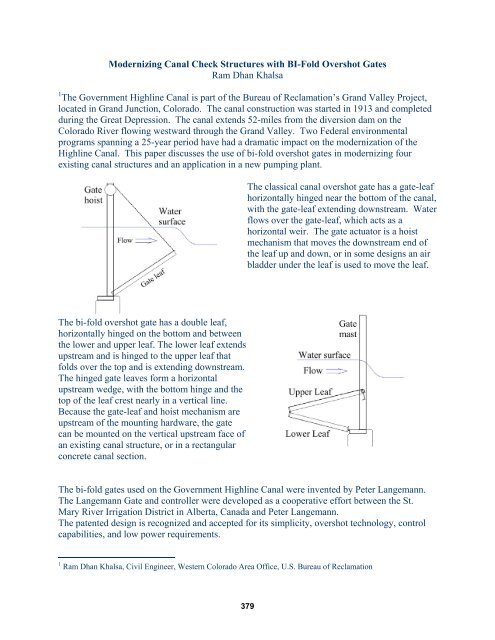
Modernizing Canal Check Structures with BI-Fold Overshot Gates

You also want an ePaper? Increase the reach of your titles
YUMPU automatically turns print PDFs into web optimized ePapers that Google loves.
<strong>Modernizing</strong> <strong>Canal</strong> <strong>Check</strong> <strong>Structures</strong> <strong>with</strong> <strong>BI</strong>-<strong>Fold</strong> <strong>Overshot</strong> <strong>Gates</strong>Ram Dhan Khalsa1 The Government Highline <strong>Canal</strong> is part of the Bureau of Reclamation’s Grand Valley Project,located in Grand Junction, Colorado. The canal construction was started in 1913 and completedduring the Great Depression. The canal extends 52-miles from the diversion dam on theColorado River flowing westward through the Grand Valley. Two Federal environmentalprograms spanning a 25-year period have had a dramatic impact on the modernization of theHighline <strong>Canal</strong>. This paper discusses the use of bi-fold overshot gates in modernizing fourexisting canal structures and an application in a new pumping plant.The classical canal overshot gate has a gate-leafhorizontally hinged near the bottom of the canal,<strong>with</strong> the gate-leaf extending downstream. Waterflows over the gate-leaf, which acts as ahorizontal weir. The gate actuator is a hoistmechanism that moves the downstream end ofthe leaf up and down, or in some designs an airbladder under the leaf is used to move the leaf.The bi-fold overshot gate has a double leaf,horizontally hinged on the bottom and betweenthe lower and upper leaf. The lower leaf extendsupstream and is hinged to the upper leaf thatfolds over the top and is extending downstream.The hinged gate leaves form a horizontalupstream wedge, <strong>with</strong> the bottom hinge and thetop of the leaf crest nearly in a vertical line.Because the gate-leaf and hoist mechanism areupstream of the mounting hardware, the gatecan be mounted on the vertical upstream face ofan existing canal structure, or in a rectangularconcrete canal section.The bi-fold gates used on the Government Highline <strong>Canal</strong> were invented by Peter Langemann.The Langemann Gate and controller were developed as a cooperative effort between the St.Mary River Irrigation District in Alberta, Canada and Peter Langemann.The patented design is recognized and accepted for its simplicity, overshot technology, controlcapabilities, and low power requirements.1 Ram Dhan Khalsa, Civil Engineer, Western Colorado Area Office, U.S. Bureau of Reclamation379
Before embracing the technology for other applications <strong>with</strong>in the irrigation project, the decisionwas made to install and test one Langemann Gate in an existing three bay stop-log structure, sixmiles from the river diversion. The stop-log structure had three 7-foot wide bays that create afore-bay pool for a hydraulic pump turnout. Significant flow changes in the canal requiredadding or removing stop-logs in an attempt maintain a stable water surface level in the fore-bay.This type of control was difficult. The original check structure was made by forming fourmassive vertical concrete gussets that create the three 7-foot wide bays. To help install the stoplogs,the stop-log slots and gussets were sloped.To provide a vertical surface to mount the Langemann gate, the center two gussets were cut tocreate two vertical columns. A short concrete stem-wall was doweled into the base of theconcrete structure.The base beam sets on a stepped stem-wall and the hoist channels are supported by vertical steelangle sections bolted to the inside of the outside concrete gussets. The assembled gate wasplaced into the modified structure using a crane.The gate functions as a vertically adjustable weir. The long horizontal gate-leaf slices throughthe canal current like a wing. The forces are somewhat balanced; the lower-leaf has an up liftingforce that is countered by the downward force on the upper-leaf. With this “balanced” load it ispossible to operate the gate hoist <strong>with</strong> a fractional-horsepower DC motor, which is powered bybatteries. The batteries can be charged either by solar panels or an AC/DC battery charger.Gate automation is accomplished <strong>with</strong> a Programmable Logic Controller (PLC), <strong>with</strong> openarchitecture, that can be easily programmed to run custom control algorithms. Standard controloptions for a Langemann <strong>Gates</strong> are upstream water level control and flow control, although themanufacturer will customize the control to the user’s need. In addition, this gate was supplied<strong>with</strong> an optical encoder to determine gate position, rather than the typical potentiometerindicator.380
The purpose of this installation was to maintain a constant upstream water surface level in thepump fore-bay. The completed installation has a 25-foot wide automated bi-fold overshot gate,mounted in a modified 90-year old three bay concrete stop-log structure. The gate performswell, running on the manufactures automation software, and the decision to install fouraddisional gates on the irrigation project was implemented.The second site is six miles downstream from the first gate. This structure contained aWaterman D-450 Amil gate and six stop-log bays, three on each side. The purpose of this canalcheck was to change and maintain the upstream water surface in the canal to prevent upstreamfreeboard encroachment at high canal flows, and to allow upstream turnout deliveries to be madeduring low canal flows. Although the structure was built in the 1990’s, it was poorly designedand did not work. The Amil gate performed as expected but it was not the correct device for thisapplication.Amil gates have a trapezoidal gate-leaf and massive concrete buttresses. A large concrete sawwas used to cut the buttresses from the floor of the structure. The Amil gate, the concretebuttresses, and one stop-log bay on each side of the of the buttresses were removed. A shortconcrete stem-wall was doweled into the floor of the check structure.A 28-foot Langemann gate was installed in the open span. There is a small difference in watersurface elevation across the gate-leaf, so that the hydrostatic pressures are nearly equal. Of the381
emaining stop-log bays, the two adjacent to the Langemann gate were fitted <strong>with</strong> manuallyoperated electric sluices gates. These gates are open during high canal flows and closed duringlow flows. The outer most stop-log bays are only half the depth of the canal and the stop-logsare permanently in place. The automation at this canal check is accomplished by the Langemanngate, similar to the previous pump fore-bay Langemann gate.The third gate was placed at the entrance of an 800 CFS siphon crossing the Colorado River.The purpose of this installation was to maintain automated flow control and flow measurementinto the siphon.Over 1600 CFS is diverted into the Highline <strong>Canal</strong> at high demand. A bifurcation five milesdownstream in the canal splits the flow approximately in half. Originally the bifurcation wascontrolled using two radial gates, <strong>with</strong> hand-crank gate hoists. One radial gate controls theHighline <strong>Canal</strong> and the other controls the siphon. The gate on the Highline <strong>Canal</strong> had beenrebuilt recently, and as part of the canal modernization, it was upgraded <strong>with</strong> an automatedelectric hoist. This radial gate controls the upstream water level in the bifurcation.The Langemann gate, in the entrance to the siphon, is used to control flow. The installation wassimilar to the previous Langemann gates, but flow conditions were different. The entrance watervelocity is over 6-feet/second and the water freefalls over the gate-leaf into the throat of thesiphon. Even though the bi-fold leaf balances the approach velocity head on the gate, thehydrostatic difference across the leaf causes the gate to want to float.To counteract this lift force, the bottom beam of the gate was securely anchored to the concretestem-wall and the upstream side plates were bolted to the concrete side walls. The greaterhydrostat force across the gate-leaf required high inrush current to the motor to start the gatemoving. Because of increased the inrush current through the motor, the DC motor solenoids were382
eplaced <strong>with</strong> a solid-state soft-start device. DC motor soft starters were installed on all five ofthe project gates, and are now standard equipment on Langemann gates.One unexpected site improvement was a great reduction in the trapped air belching back fromthe siphon inlet. The high velocity discharge under the old radial gate pulled air into the siphon.The water velocity over the Langemann gate-leaf is reduced and the energy is dissipated in thesiphon intake. The gate at this site is presently operated in local hand mode. When it is tied intothe SCADA radio network, it will be locally automated and remotely operated.The forth gate was placed downstream of an emergency siphon on a side-channel spillway fromthe canal. The purpose of this installation is to maintain an automated constant upstream watersurface in the canal, and to measure the canal water administratively spilled into Highline Lake.Historically the siphon would be started by a high water level in the canal and then break suctionwhen the canal water level was drawn down ½-foot. With the Langemann gate installed in thespillway, the three sluice gates in the bottom of the canal are opened and the siphon isinoperative.This Langemann gate has the same hydraulic control challenges as the gate at the bifurcationsiphon inlet. The lake spill is 44-miles from the canal diversion point, and there are a series of14 canal check structures upstream from the spill. The canal checksare operated in upstream control mode, and the miss matches between canal diversion andirrigation deliveries are accumulated downstream at the Highline Lake spill. This gate is 13-feetwide and the spill flow ranges from 0 to 200 CFS. The gate must respond quickly to maintainthe canal water surface level. The PLC algorithm control time step was shortened to make thegate move aggressively.383
The fifth gate was placed at the entrance of the Highline Lake pump back station. The pumpstation is operated to supplement canal supply during short-term increases irrigation demand.The purpose of this gate installation is to prevent debris from building up on the pump screenswhen the pumps are not running. A trash rake cleans the screens when the pumps are operation.A low water level in the canal will cause the Langemann gate in the spillway to rise and stop thespill. If the canal water level falls below the pump target level, the pump PLC will lower thepump station Langemann gate in front of the screens prior to starting the pump. When thepumps stop, the gate is raised to block debris from entering the screens.Conclusion: <strong>Canal</strong> modernization, <strong>with</strong> bi-fold overshot gates was very successful on theHighline <strong>Canal</strong>. The gates performance well in a variety of water control applications. Thesegates are custom engineered for each site and designed <strong>with</strong> the water control feature desired bythe user. The low power requirement and the minimal concrete work needed for installations,makes the Langemann gate a versatile and economic tool for modernizing old canals orconstructing new canals.References: Personal contact <strong>with</strong> Gerald Robinson, R.E.T., Aqua Systems 2000 Inc.384