NEH 16 Chapter 1 - NRCS Irrigation ToolBox Home Page
NEH 16 Chapter 1 - NRCS Irrigation ToolBox Home Page
NEH 16 Chapter 1 - NRCS Irrigation ToolBox Home Page

You also want an ePaper? Increase the reach of your titles
YUMPU automatically turns print PDFs into web optimized ePapers that Google loves.
Classification of drainage methodsThe methods used for land drainage may be classified in two broad categories--surface drainage and subsurface drainage--depending on the way the water isremoved.1. In surface drainage, land surfaces are reshaped as necessary toeliminate ponding and establish slopes sufficient to induce gravitationalflow overland and through channels to an outlet. Surfacedrainage may be d'ivided into works whicha. remove water directly from land by land smoothing, land grading,bedding, and ditchingb. divert and exclude water from land by diversion ditches, dikes,and floodways.2. In subsurface drainage, ditches and buried drains are installed withinthe soil profile to collect and convey excess ground water to a gravityor pumped outlet. The drop in pressure resulting from discharge inducesthe flow of excess ground water through the soil into the drains.a. Interceptor drains are used to prevent entry upon the land whenground water moves laterally. Drains are oriented .approximatelyat right angles to the direction of ground-water flow.b. Relief drains are used when land surfaces are nearly flat, flowvelocities low, or interception of ground water ineffective.Drains are commonly (but not necessarily always) oriented approximatelyparallel with the direction of ground-water flow.Development of drainage-design criteriaDesign criteria are developed in two general ways: (a) from empirical datacollected through evaluation of existing drainage systems, and (b) from atheoretical analysis of the problem, applying known physical laws and testingthe theory through.evaluation of existing drainage systems.An example of empirical criteria are the drainage coefficients used in designof drains in humid areas. Such coefficients are the removal rates for excesswater, found by experience with many installed drainage systems, to provide acertain degree of crop protection. Such protection has been assessed carefullyagainst observed crop response and production, measurements of flow from drainagesystems providing good drainage, and measured heights of water table. Sinceempirical criteria are based substantially on experience and assessments ofnumerous interrelating factors, care must be taken in transposing their use fromone locality to another.Theoretical analysis applies proved principles or laws to problems having knownlimiting conditions. The resulting mathematical expression explains the observedaction of existing drainage systems and permits the rational design of newsystems. Usually several variable site factors enter the expression. An exampleof the theoretical analysis is the ellipse equation for spacing subsurface drainsin irrigated land, where known site characteristics are accounted for in theequation. In one form of the ellipse equation, the variables are hydraulic conductivityof the soil, depth to impermeable layer, depth to the water table at
midpoint between the drains, and rate water is to be removed. By substitutingknown or estimated values for these factors, the equation may be applied to avariety of sites, as long as the site conditions are within the limits for whichthe equation was derived. This last requirement is all important in using thiskind of theoretical approach.Whichever method is used to establish drainage-design criteria, it is evidentthat its value depends not only on sound analysis of the drainage situation butalso on evaluation of installed drains to check their performance.Types of Drainage ProblemsSuccessful drainage of a wet area depends on a correct diagnosis of the problem.At some sites, a brief field study and comparison with previous installationsunder similar conditions may be a sufficient basis for design. More complexdrainage problems require more detailed reconnaissance and preliminary surveysto determine the source of damaging water, how water reaches the wet area, andwhat design criteria apply. The drainage system may be designed, however, onlyafter the nature of the problem has been identified.The following typical drainage problems have been divided into surface and subsurfaceproblems for convenience. Actually, wet land may involve both surfaceand subsurface water, and the drainage design should consider their interdependence.Surface-drainage problemsFlat and nearly flat areas of land are subjec~ to ponded water caused by:1. Uneven land surface with pockets or ridges which prevent or retardnatural runoff. Slowly permeable soils magnify the problem.2. Low-capacity-disposal channels within the area which remove water soslowly that the high water level in the channels causes ponding on theland for damaging pefiods.3. Outlet conditions which hold the water surface above ground level, suchas high lake or pond stages, or tidewater elevations.Sources of surface water are rainfall or snowmelt on the area itself, irrigationsurfacewaste, runoff or seepage from adjoining higher land, or overflow fromstream channels.Surface-drainage methods, such as land grading or smoothing and field ditches,are used on fields to collect and convey surface water to natural channels orconstructed disposal systems. Inadequate outlets may require downstream-channelimprovement, levees with culverts and flapgates, or drainage pumps. Diversionsystems are efficient in preventing or reducing the ponding of surface waterwhere the source is outside the area to be protected. These and other featuresof surface-drainage systems will be described more fully in other chapters.Subsurface-drainage problemsSubsurface-drainage problems arise from many causes. Flatland tends to be poorlydrained, particularly where the subsoil permeability is low. There are many wetareas, however, where there is no evident connection between the area of seepage,or a high water table, and the topography of the site. High water tables may
occur where the soil is either slowly or rapidly permeable, where the climate iseither humid or arid, and where the land is either sloping or flat.For these reasons, it is convenient to classify subsurface-drainage problems bythe source of excess ground water and the way it moves into and through theproblem area. This method of identifying subsurface conditions is especiallyuseful for the more complex drainage problems because it also indicates the kindof drainage system needed. The reconnaissance and preliminary surveys are carriedout to obtain the needed information on ground-water occurrence and othersite conditions. Detailed information is in <strong>Chapter</strong> 2, Drainage Investigations.As experience with subsurface-drainage problems accumulates for a given area,the amount of preliminary information needed to identify certain problem typesusually is reduced. New areas or new kinds of drainage problems require greateremphasis at the preliminary stage of planning.The following examples illustrate some of the more important types of subsurfacedrainageproblems. Particular emphasis is given to the source and direction ofground-water flow. Detailed design of drainage systems for subsurface drainageis discussed in <strong>Chapter</strong> 4, Subsurface Drainage. Refer to the figures in <strong>Chapter</strong>4 for illustration of most of the drainage problems described below.Basin-type free-water tableIn valley bottoms and on wide benchlands, the free ground water saturates thesediments down to the first impervious barrier. Typically, the water tableslopes gently downvalley. This large, very slowly moving body of ground wateris fed by springs, surface streams, or subsurface percolation around the perimeterof the valley; and by infiltrating rainfall, irrigation losses, or surfacerunoff on the valley floor itself. Eventually, the ground water dischargeseffluent seepage at streambanks or at the ground surface in low areas, or exceptfor ground water used by plants or that pumped from wells, it escapes throughaquifers at the lower end of the valley or benchland. Height of the water tablefluctuates with the seasonal variation of accretions to the ground-water basin.The general slope of the water table varies only slightly in response to thesechanges in inflow. Where salts are present in the soil, they tend to move upwardto the surface as capillary rise replenishes the evaporation from the ground.Phreatophytes grow where the water table is close to or at the surface.Relief drains may be used to lower the water table in such areas, unless soilpermeability is too low. The ground-water slope is too nearly flat and thepervious sediments are too deep for efficient interception (except, perhaps, atthe sides of valleys near the base of the hills or the alluvial cones). Whereeconomically feasible, pumped-drainage wells are sometimes used to lower thebasin-type water table.Water table over an artesian aquiferGround water may be confined in an aquifer so that its pressure surface (elevationto which i; would rise in a weli tapping the aquifer) is higher than theadjacent free-water table. The pressure surface may or may not be higher thanthe ground surface. Such ground water is termed artesian. Pressure in theaquifer is from the weight of a continuous body of water extending to a sourcehigher than the pressure surface. Leaks at holes or weak points in the confininglayer above the aquifer create an upward flow, with hydraulic head decreasing inthe upward direction. The ground water moves in response to this hydraulicgradient and escapes as seepage at the ground surface above, or it escapeslaterally through other aquifers above the confining layer.
A water table supported by artesian pressure usually is more difficult to lowerand maintain at the desired height than a water table not subject to suchpressure. This is because water is continuously replenished from the highersource and because it is difficult to remove or control water at the source.Wet areas overlying water under artesian pressure require relatively deep andclosely spaced drains, relief wells, or pumped-drainage wells that tap theaquifer. Such areas may be impractical to drain.The drainage system required to control artesian flow may depend on the kind ofunderlying material. The upward flow from the source aquifer may reach thewater table through a stratum of fairly uniform material, or it may pass throughfractures or other narrow openings in sandstone, clay, lava, limestone, or othermaterials that in themselves are practically impermeable. Surface seeps in someplaces are caused by artesian flow that wells up through relatively small openingsin the confining material, causing ground-water mounds or surface seeps. Thiskind of seep usually may be drained by placing a relief drain as deep as practicablethrough the seepage zone. Additional intercepting drains may be needed topick up flow that escapes laterally above the confining layer.Perched-water tableIn stratified soil, a subsurface-drainage problem may be caused where excesswater in the normal root zone is held up by a layer of low permeability so thatthe perched water is disconnected from the main body of ground water. This mayoccur when surface sources build up a local water table over the slowly permeablelayer. Lateral percolation is too slow to drain the perched water naturally.Drainage systems for perched-water tables are based on the particular site conditions.Usually they consist of relief drains, but an interception drain maybe effective in cutting off lateral seepage into the wet area. Theoretically,perched water could be drained downward by drilling vertical drains (wells)through the restrictive layer. A collection-drain system probably would benecessary, however, and the vertical drains might be impractical outlets foreconomic or other reasons. Perched-water tables in irrigated areas may be subjectto control by reducing seepage from canals, by improving irrigation practices,or by providing adequate surface drainage.Lateral ground-water flow problemsThis group of subsurface-drainage problems is characterized by more or lesshorizontal ground-water percolation within or toward the crop-root zone. Theflow pattern is strongly influenced by soil stratification and other naturalbarriers to flow.Adjacent soil layers often have permeabilities that differ a hundred or a thousandfold. According to Darcy's law of flow, the effective velocity under agiven gradient varies directly with the permeability. Flow of ground water isdiscussed further in the section on "Subsurface-~raina~e Principles." Allsignificant flow may be limited to the more permeable layers. The depth,orientation, and inclination of the strata determine the drainage method andlocation. For example, hillside seepage may appear where ground water moveslaterally over bedrock or over a layer of fine sediments to a point where itemerges at the surface. One or more intercepting drains may be used to cut offthe flow which otherwise would reach the root zone.Alluvial fans and valley bottoms commonly contain sand or gravel deposits. Theseoccur in a variety of ways, as in deep extensive layers, narrow "stringers"(old streambed locations), lenses, or in highly stratified soil profiles. Such
apidly permeable deposits may serve as channels for ground-water movement insome places at high rates of flow. A soil layer of low permeability overlyingsuch an aquifer may create a degree of confinement, which in turn develops anupward hydraulic gradient, particularly if the lower end of the aquifer is closedor of reduced permeability. Interception drains are effective where the aquiferis close enough to the surface so that it is feasible to cut off the flow.Relief wells or pumping may be used where interception is not practical.Subsurface soil masses of low permeability, such as clay lenses and offshoreclay bars formed in the geologic past, are local barriers to ground-water flow.They may cause the water table to be held to a high level and the flow to escapearound or over the barrier. Permeable layers that become thinner or graduallydecrease in permeability in a downstream direction have a similar effect on thewater table. Drains placed just upslope from the restriction usually are effectivein these situations. <strong>Irrigation</strong> canal seepage creates another kind oflateral ground-water flow problem. An intercepting drain at the toe of a canalbank or river levee may cut off much of the flow that would reach the wet areawhere a horizontal barrier forms a convenient "floor" for interception. However,the designer must consider the steeper hydraulic gradient such a drain causesand evaluate its effect on the canal-seepage loss and on the stability of theembankment against sloughing or piping. River seepage through or under leveescreates similar problems.These examples illustrate the unlimited variety of subsurface-drainage problems.The principles of interception, relief, or pumped-well drainage may be appliedto each according to the pattern of subsurface flow. The pattern of flow becomesknown from a field investigation of soil stratification, water source, and watertable or pressure data.Differences in Drainage in Humid and Arid AreasDrainage in humid areas has to do largely with excess water resulting from precipitation;in arid and semiarid areas, the need for drainage arises principallyfrom irrigation, with foreign ground water an important source in some areas.Surface-drainage systems may be required in either humid or in irrigated areas.Surface drainage ia usually an integral part of irrigation systems on slowlypermeable soils or in areas of high precipitation rates.The purpose of subsurface drainage is to lower the water table to a point whereit will not interfere with plant growth and development. The minimum depth atwhich the water level should be maintained varies according to both the croprequirement and the soil. One of the principal factors in the height of thewater table in arid areas is control of salinity and alkalinity in the soil andground water. This is a major reason for theadifference in the subsurfacedrainage of humid and of arid climates.The depth of drains in humid climates is generally 3 to 5 feet. Water isrelatively pure, there usually is a natural excess of water over plant requirements,and there is a net downward movement of ground water.Soils in semiarid or arid climates require subsurface drains at least 5 to 7 feetdeep. Most of the water needed by the crop is added by irrigation. Usuallyground water is somewhat saline because of salts in the soil, the irrigation water,or both. A water table as high as 24-30 inches below the surface, suitablein many humid areas, would create a harmful salt concentration in the root zonein arid areas.
Effects of excess water on cropsCrop RequirementsThe growth of most agricultural crops is sharply affected by continued saturationof any substantial part of the root zone or by ponded water on the surface.Poorly drained soils depress crop production in several ways:1. Evaporation, which takes heat from the soil, lowers soil temperature.Also, wet soil requires more heat to warm up than does dry soil, dueto the high specific heat of water as compared to that of soil. Thus,the growing season is shortened.2. Saturation or surface ponding stops air circulation in the soil and preventsbacterial activity.3. Certain plant diseases and parasites are encouraged.4. High water table limits root penetration.5. Soil structure is adversely affected.6. Salts and alkali, if present in the soil or ground water, tend to beconcentrated in the root zone or at the soil surface.7. Wet spots in the field delay farm operations or prevent uniformtreatment.Drainage requirements determined by cropsDifferent crops have widely differing tolerances for excess water, both as toamount and time. While water itself may not be injurious to plant roots,saturation of the root zone results in an oxygen deficiency and accumulation oftoxic gases. A short term of oxygen deficiency can reduce water uptake, nutrientuptake, and root respiration and build up toxins which leads to death of cellsand roots, and, if extended, the death of the plant itself. However, completesaturation of roots over an extended period may cause no serious damage if itoccurs during dormant periods of plant growth or flow from drainage is sufficientto supply some oxygen and remove toxic gases. The designer of a drainage systemrecognizes these differences in crop requirements by selecting an appropriatedegree or intensity of drainage (often termed the drainage requirement) for thesite. The drainage requirement is based on (a) the maximum duration and frequencyof surface ponding, (b) the maximum height of the water table, or (c) the minimumrate at which the water table must be lowered. The local drainage guide indicatesthe drainage criteria required for various crop-soil combinations. Further informationand guidance can be obtained from reports of continuing research on effectsof flooding, water table depths and soil gases on agricultural crops (2).Crop growth and the water tableThe water table may be defined as the upper surface of the saturated zone of free,unconfined ground water. (A more accurate definition has been made in terms ofwater pressures and film tensions.) The soil-moisture content for a significantheight above a water table is substantially greater than field capacity. For thisreason, plant-root growth is affected by a water table much more than the heightof water table alone indicates.
Bernoulli's theorem is used to compute the hydraulic gradeline for steady-flowconditions. Losses of head due to friction are computed by an open-channelformula, usually Manning's. Head losses at constrictions causing nonuniformflow, such as at bridges or culverts, are computed by formula using appropriateloss coefficients. The field survey must include sufficient information forevaluation of the roughness and cross-section factors, including head loss throughobstructions.In drainage design, nonsteady flow may occur as in discharge into tidal streams.Such problems may sometimes be solved by dividing time into convenient incrementswithin each of which the varying flow may be taken as a constant, mean-flow rate.Forms of soil waterSubsurface-Drainage PrinciplesGravity waterWater that is free to move downward through the soil by the force of gravity iscalled gravity water. At saturation, all pores are filled and the soil holdsthe maximum amount of water that can be absorbed without dilation. (Dilationis the bulking or flotation of soil grains.)Capillary waterCapillary water is held in the soil against gravity. It includes the film ofwater left around the soil grains and the water filling the smaller pores aftergravity water has drained off.If gravity water is allowed to drain from a saturated soil (not influenced bya water table), the quantity of capillary water held is called field capacity.Close to the water table, the quantity of capillary water held in a granularmaterial is greater than field capacity. The amount of water held at a givenpoint depends on the distance above the water table, as well as on the soil poresizes and shapes. This form of capillary water is sometimes called fringe water.Just above the water table, fringe water completely fills the capillary pores,and in this relatively narrow zone, saturation occurs at slight negative pressure(tension). Openings so large that capillary rise in them is negligible arecalled supercapillary openings. Examples of materials containing supercapillaryopenings are gravel, boulders, some forms of lava, structurally fractured rockor clay, solution openings in rock, and soil containing root holes.Hygroscopic waterWhen a granular material is completely dried by heating, then exposed to the air,it absorbs atmospheric moisture. This water, when in equilibrium with theatmospheric moisture, is called hygroscopic water.The water table and the capillary fringeThe water table is the upper surface of the saturated zone of free ground water.Free ground water is defined as water neither confined by artesian conditionsnor subject to the forces of surface tension. At the water table, water pressureis at atmospheric pressure. Thus the water table is the imaginary surface separatingcapillary water (under tension) from the free ground water below.The water table in granular material is not an observable, physical surface becausecapillary water saturates the material just above the water table anddecreases in amount gradually upward. An exception is water in supercapillary
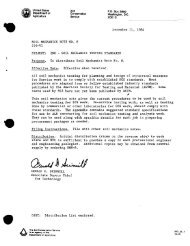
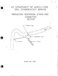
openings, in which the water is in equilibrium with the atmosphere. Auger holesand piezometers are supercapillary in size and open to the atmosphere, and sothey fill to the true water-table level when bored or driven just into the watertable.When an auger hole is bored to locate the water table in a fine or mediurntexturedsoil, the observer finds it difficult to recognize the top of thesaturated zone because of the gradual change from moist to saturated soil. Also,it may take hours or even days for an auger hole to register the water table inslowly permeable soils. Small wells or piezometers react more quickly than largeones because less water need flow through the soil to fill the smaller openings.Water in the capillary fringe may be a significant proportion of ground watermoving toward subsurface drains--as much as 20 percent or more under someconditions.An auger hole or pipe should penetrate the saturated zone only a short way if thewater-table elevation is to be measured accurately. This is particularly importantwhere upward flow or confined flow would be tapped by a deeper hole. Anauger hole that penetrates two or more aquifers in a stratified soil containingconfined water would register the highest hydraulic head modified by leakagefrom the aquifers of higher hydraulic head to those of lower head.These characteristics of the water table have a significant bearing on the kindof field measurements to be made, on the devices used to make the observations,and on the interpretations of data for drain-system design.Principles of flow in the saturated zoneFlow of water in the saturated zone involves mechanical, chemical, and thermalenergy, and molecular attraction. A full discussion of soil-water movement isin numerous publications on soil physics and soil permeability. Here only themechanical forces tending to move water through soils will be considered.Hydraulic headIn saturated flow through soils, as in open channel flow, the total energy content(E) of water is the sum of the kinetic, pressure, and gravity components.As expressed in Bernoulli's equation:E = kinetic energy -I- pressure potential + elevation potential.Velocities in ground-water flow are almost always low, making the velocity(kinetic) term negligible. Essentially, then, the energy causing flow is thesum of the two potential energy items, pressure and elevation. This potentialfor flow is called "hydraulic head."In the English system of units, energy is expressed foot-pounds. Hydraulic headis conveniently expressed as the energy content per unit weight of water, orfoot-pounds per pound, which is feet, dimensionally. Thus, the hydraulic head(fig. 1-l), at a given point is:where H = hydraulic head, ft.; P = pressure at the point referred to the atmosphere,lb/ft2; W = specific weight of the water, lb/ft3; and Z = elevation ofthe point above a datum, ft.
--Pressure Headat Point "P" =Elevation Headat Point "P" =7 r YDATUMFigure 1-1, Illustration of hydraulic headHydraulic Gradient = HI- HzLFigure 1-2, Illustration of hydraulic gradient
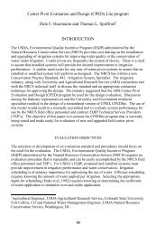
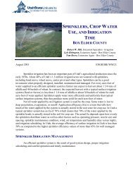
Piezometers convert pressure at a point to a physical pressure head the heightof the water column in the piezometer. This height is not hydraulic head, sinceit is only the term P/W in the equation. To find the hydraulic head at the point(lower end of the piezometer) the elevation (Z) of the point above the datum mustbe added to the pressure head. The elevation of the water surface in the piezometer,referred to the datum, is P/W + Z, and so is numerically equal to thehydraulic head at the lower end of the piezometer.Hydraulic gradientGround-water flow results from the force "available" to move water through thesoil due to differences in energy content; i.e., differences in hydraulic head.This is analagous to the flow of heat or electricity, where flow is due todifferences in temperature (heat potential) or differences in voltage (electricalpotential). Hydraulic gradient is the difference in hydraulic head at two points,divided by the distance between the points measured along the path -- of flow(fig. 1-2). In this figure, the plane of the paper is a vertical surface throughthe path of flow.Hydraulic Gradient =H1 - H2where L = distance measured along the path of flow, ft.Subscripts 1 and 2 refer to the points of the higher and lower hydraulichead, respectively; other units are defined in the preceding paragraphs.In a given flow system (fig. 1-3) each "particle" of water in the system has itscorresponding hydraulic head. All particles or points, of a given hydraulic head(Hi) lie in the corresponding equipotential surface (HI). All points of hydraulichead H2 lie in the equipotential surface Hz, and so on. The force tending to produceflow acts in the direction of greatest decrease in hydraulic head; i.e.,normal to the equipotential surface, as F at point P, or F' at point P'. Themagnitude of this force is proportional to the hydraulic gradient at the point.At the water table, the pressure component of energy (P/W) is zero relative toatmospheric pressure. Therefore, the hydraulic head H of a point at the watertable is Z, the elevation of the point above the datum.Water-table slope represents the hydraulic gradient of flow only under certainconditions. Hydraulic gradient may differ greatly from the water-table slopewhere there is significant upward or downward component of flow such as in thevicinity of pumping wells or subsurface drains, in flow from artesian aquifers,and in unsaturated seepage from canals. As shown in figure 1-4, slope of thewater table is H1 - H2 (or tangent of the angle) by definition. S is the hori-Szontal projection of the path of flow L. But the hydraulic gradient is H1 - H2L(or sine of the angle). On flat gradients and with parallel flow, the watertableslope is essentially the hydraulic gradient because S = L nearly (tangentis nearly the same as the sine for small angles). It should be noted that the
Figure 1-3, Equipotenrial surfaces--.. 2,--Hydraulic Gradient at Water Table =LHI - Hz1. Slope of Water Table .--1 SHI- H2Figure 1-4, Difference between hydraulic gradientand slope of the water table
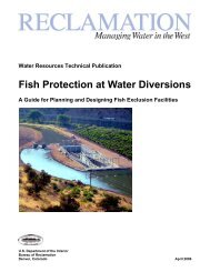
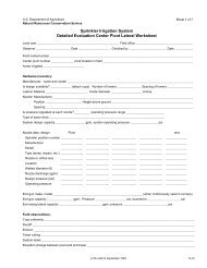
water table is not invariably a path of flow; water may be flowing down from orup into the unsaturated zone, thus crossing the water table.Paths of flow (streamlines)The force due to hydraulic gradient tends to move water along the line of forcenormal to the equipotential surfaces. Whether the flow moves actually in thesame direction as the line of force depends on whether the soil has the samehydraulic conductivity in all directions. If the soil is "isotropic," i.e., ifits hydraulic conductivity is the same in all directions, the path of flow willbe along the lines of force and perpendicular to the equipotential surfaces.If the soil has a higher hydraulic conductivity in one direction than in anotherdirection, the path of flow will not be perpendicular to the equipotential surface.Such a soil is said to be "anisotropic." Water-laid soils often havebedding planes or particle orientation causing them to be anisotropic. Thepaths of flow in anisotropic soils will be perpendicular to the equipotentialsurfaces at points where the lines of force are exactly parallel to or normalto the bedding plane. A soil with microstratification (thin layers with widelydifferent hydraulic conductivities) will cause water to flow in a way similarto the flow in an anisotropic soil.Many flow systems common in soil drainage may be studied in two dimensions ratherthan three, because of uniformity in the third dimension. Equipotential linesthen represent the intersection of the plane of the paper with the equipotentialsurfaces. An example of this representation is the flow into a system of paralleldrains, where the flow is at right angles to the drains.A two-dimensional system on the X-Y plane is illustrated in figure 1-5. The soilis isotropic (hydraulic conductivity is uniform in all directions) in figure 1-5.Figure 1-6 shows another soil, with a line of force normal to the equipotentialline and at an angle b to the vertical axis Y. But in this soil, which isanisotropic,the horizontal hydraulic conductivity Kh exceeds the vertical hydraulicconductivity Kv. The direction of flow is not along the line of force, butalong a line closer to the horizontal axis. It may be shown that the angle thepath of flow makes with the horizontal isKa = tan-' Kh zanThus, the flow pattern may be computed and drawn for an anisotropic system ifthe equipotential lines are known, and if the relative hydraulic conductivitiesKv and Kh are known.In analyzing the direction of flow of ground water, the investigator should beaware of the effect of anisotropic soils on the flow pattern.Flow nets and boundary conditionsFlow in the saturated zone often is studied by means of graphic representationsof hydraulic head and paths of flow. Cross sections are taken through the problemarea, usually in vertical planes. Lines connecting points of equal hydraulic head
Figure 1-5, Flow direction in isotropic soilX-AXISY-AXISFigure 1-6, Flow direction in anisotropic soil
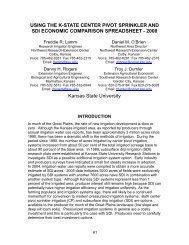
on such planes are called equipotential lines, or "equipotentials." Linesindicating the paths of flow are called "streamlines." A graph showing equipotentialsand streamlines for a flow system or part of a flow system is calleda "flow net."The flow net is the result of the operation of Darcy's Law in a system wherethere are certain sources of water and certain constraints to flow. Theseconditions that govern the pattern of flow in a ground-water system, when takentogether, are called "boundary conditions." Topography, location and quantityof water source, stratigraphy, and drain locations are the principal items makingup the boundary conditions. A field survey of these elements is a basis for(a) isolating the flow system to be studied, and (b) designing the drainagesystem.Figure 1-7 illustrates two flow nets in saturated soils. Each is taken in avertical plane at right angles to a drain, with the soil saturated to the surfaceand an impermeable layer at twice the drain depth. The drain is one of severalequally spaced drains. The upper flow net is for an isotropic soil. The lowerflow net is for the same boundary conditions except that the soil has a horizontalpermeability <strong>16</strong> times its vertical permeability (anisotropic). Numbers on eachstreamline indicate the percent of the total flow which occurs to the left ofthat streamline. Note that 50 percent of the flow reaching the drain through theisotropic soil originates in a strip over the drain and covering about one-fourthof the source area. For the soil with horizontal permeability <strong>16</strong> times greaterthan the vertical, 50 percent of the flow originates in a much wider strip,covering nearly one-half of the source area.If the water source were cut off at the soil surface, the water table would dropin both cases, but the drop would be much more uniform in the second case. Thissame effect is observed in layered soils, except that the flow net, while havingthe same general shape, would show sharp breaks in direction where the linescrossed from one stratum to another.Flow nets may be plotted from actual field measurements of hydraulic head inpiezometers. A drainage problem is sometimes reproduced in a laboratory tankmodel, from which flow data may be taken more readily. Electrical analogs provideadditional useful tools for setting up some drainage problems. Plow nets arereadily plotted from electrical analog data. There are also methods of computingarithmetically the hydraulic head throughout actual or idealized flow systems.However, numerical methods are tedious for complex problems.Flow nets are used to study such special problems as the depth and spacing ofdrains, the best location for a drain conduit designed to intercept flow overan impermeable layer, the effect of pervious backfill in less permeable soil,the quantity of flow entering the bottom half of a buried drain, and canal seepage.Such special conditions may justify flow-net analysis for an individualdrain design, but this technique is more often employed in research or evaluationwork.Permeability and hydraulic conductivity"Permeability" of a porous medium such as soil is its capacity to transmit fluids.It is used as a qualitative term; i.e., it is used as a term for this propertyof soil. The term is also modified to describe the relative ease of transmission,as "rapidly permeable," or "slowly permeable ."
ISOTROPIC SOILI -eDrainIimpervious LayerMidpointBetween Dia insDraindlmpervious LayerMidpointBetween DrainsFigure 1-7, Streamlines and equipotentials
"Hydraulic conductivity" of a soil is a numerical value for permeability. Itis equal to the proportionality factor K in the Darcy equation. The Darcyequation is an expression of effective velocity of flow as a function of hydraulicgradient and the transmission properties of the soil and water. It was found thateffective velocity is proportional to hydraulic gradient, all other things beingequal :Lwhere v = effective flow velocity, dimensions -T(Effective flow velocity is the velocity with respect to the total areaof the porous medium--not the void area alone. It may be defined asthe quantity of flow per unit of time divided by the total area of theporous medium producing that quantity of flow.)LK = a factor, dimensions -Ti = hydraulic gradient, dimensionlessThus, hydraulic conductivity is the effective velocity of flow when the hydraulicgradient is unity. In drainage design, it is convenient to express v and K ininches per hour. Darcy's Law is valid for flow velocities in almost any naturaldrainage situation.Hydraulic conductivity depends on properties both of the soil and of the transmittedwater. A high value is associated with high porosity, coarse open texture,and highly developed structure. Soils do not vary greatly in porosity, but afew large pores are more effective in contributing to high conductivity thanmany small pores. Fine-textured soils-may depend almost entirely on the structuralpores for their conductivity. The quality of the water transmitted, particularlythe salinity and alkalinity, may have a marked effect on hydraulicconductivity.Soil within a drainage-problem area seldom has uniform permeability. This variationis exhibited in two important characteristics: the soil may be nonhomogeneousdue to stratification, barriers, or other distinct masses; or it may have a higherpermeability in one direction than another, even though homogeneous. Soils withthis latter quality are called "anisotropic" (see section on "Paths of Flowt').Rate of flowThe rate of flow (Q) passing a given cross-sectional area of saturated soil (A)is the product of the area and the effective velocity of flow through the section(v) :Combining this expression with the Darcy Lawwe have the expression
This equation may be used to estimate the quantity of flow in simple drainageproblems, such as might be found in hillside interception over a sloping, impermeablelayer. In more complex flow problems, both the hydraulic gradient andthe hydraulic conductivity vary throughout the flow region and analysis is moredifficult. Also, the boundaries of flow may be difficult to determine. Forthese problems, it usually is impractical to define completely the area, p-ermeability,and hydraulic gradient, so less direct methods of estimating flow areemployed. These are discussed in <strong>Chapter</strong> 4, Subsurface Drainage.Sink formation in subsurface drainageSubsurface drainage is accomplished by placing below the water table an artificialchannel in which the hydraulic head is less than it is in the soil to be drained.Thus a hydraulic gradient toward the channel is induced, and a "sink" is creatkd.The sink is maintained, of course, by removing water from the artificial channelby gravity or by pumping.Two factors determine the rate at which water moves toward the sink at any point:The hydraulic gradient and the hydraulic conductivity. This is in accord withDarcy's Law. Total flow to the sink involves hydraulic conductivity throughoutthe whole soil mass through which water moves to the sink. The flow net delineatesthe extent and pattern of flow throughout this soil mass, as discussed onthe preceding pages.The desired control of the water table is accomplished (a) by locating the sinkvertically and horizontally so as to take advantage of the more permeable soilmasses, and (b) by controlling the hydraulic gradient. Hydraulic gradient maybe controlled through depth of the sink, spacing of the sinks, and (in methodsof drainage) the pressure at the sink. In Equation 1-1Hydraulic gradient =P(++zl)P- ($ + z,)these three controls affect Z2, L and P2, respectively.LDrainage devices that are used'to form sinks are buried drains, ditches, reliefwells (upward flow), vertical drains (downward flow), and pumped wells. Thehydraulic head in buried drains and in ditches depends on the water-surface elevationbecause the water is at atmospheric pressure. Relief wells, at theirlower ends where the sink usually is formed, operate under a pressure dependenton the elevation of their outlets--or of the water surface in the drain intowhich they discharge, if submerged. Pumped wells create sinks which may beeither at atmospheric pressure or above atmospheric pressure, depending on thesoil stratification and whether the sink in question is above or below the waterlevel in the pumping well.Theories of Buried Drain and Open Ditch Subsurface DrainageWater movement in the saturated zone may be analyzed by applying Darcy's Law tothe particular set of boundary conditions at the drainage-problem site. If itwere possible by field surveys to determine the exact location of impermeablelayers, the location and hydraulic head of all inflow to and outflow from thesystem, permeability in all parts of the system, time and rate of changes in flow,symmetry of the system--all the factors which affect the amount and pattern offlow--then the problem would be completely defined and subject to direct andexact solution.
Drainage problems are seldom so completely defined in practice, however. Usuallythey consist of a more or less complex combination of different problems. Theprocedure is to determine the boundary conditions, first approximately, then inas much detail as necessary by means of the reconnaissance and preliminary surveys.Certain situations or sets of boundary conditions are recognized as problem typesfor which experience or analysis has given us design criteria. After identificationof the problem type, the necessary field measurements and investigations aremade so that design criteria may be applied. For some drainage problems, thereare few numerical criteria, if any, and the designer relies mostly on good judgment.But in all drainage problems the basic procedure is that previouslyoutlined.Drainage theories have been developed to describe or to attempt to describe theaction of a given saturated flow system. They are useful in getting an approximatesolution to actual field problems. To use them, the designer must comparethe field situation with the underlying assumptions on which the drainage theoriesare based. He then applies such of them as his judgment indicates are mostapplicable. Both steady state and nonsteady state problems are encountered indrainage work. The following approximate theories have been applied to one orboth types of problems.Classification of drainage theories by basic assumptionsHorizontal flow theoriesThese approximation theories are based on two assumptions: (a) that all streamlinesin a gravity flow system are horizontal, and (b) that the velocity alongthese streamlines is proportional to the slope of the free-water surface, butindependent of depth.Although it can be shown that these are erroneous assumptions, (see "HydraulicGradient'' page 1-12) the theory of horizontal flow gives sufficiently accurateresults if its application is restricted to situations where the flow is largelyhorizontal. Three field conditions of this kind are:1. Open ditches that are shallow compared to their spacing and that penetrateto or are close to an impermeable layer.2. Open ditches that are excavated in stratified materials.3. Buried drains under conditions 1 and 2, particularly if the backfilledtrench is more permeable than the undisturbed material.One expression of the horizontal flow theory is the ellipse equation, of whichthe tile-spacing formula developed by Donnan (3) is one form. Application ofthe ellipse equation is discussed in <strong>Chapter</strong> 4, Subsurface Drainage.Visser (4) in another application of the ellipse equation, extended it to applyto nonsteady state problems. His method was developed for conditions in theNetherlands, but according to Van Schilfgaarde, Kirkham, and Frevert (5), themethod possibly could be applied profitably in irrigated areas of the arid regions.Radial flow theoriesA tile line may be thought of as a horizontal well, with water approaching thetile along radial streamlines. This analogy is the basis for the radial flowtheories, which assume (a) a homogeneous isotropic soil of infinite depth, and(b) a flat water table. 'This method can give a good approximation of actual flow
conditions if the curvature of the water table is small (as with a low rainfallrate and relatively high permeability), and if below the drain there is no layerof greatly reduced permeability.Combined horizontal and radial flow theoriesHooghoudt (6) and Ernst (7) have developed solutions of the flow problem bycombining the radial and horizontal flow hypotheses. These solutions correctthe major shortcoming of the ellipse equation (neglect of convergence of flownear the drain). They are valuable and reliable approximations for the steadystateproblem of removing steady rain or equivalent accretion.Hooghoudt modified the ellipse equation by introducing an "equivalent depth,"and he prepared extensive tables of the equivalent depth for solution ofsteady-state problems. Visser (4) reports on a nomographic solution based onthe same general assumptions as Hooghoudt's method, and Van Beers (8) has developednomographs for calculation of drain spacing according to the Hooghoudt and Ernstformulas .Van Deemter's (9) hodograph analysisThis is a mathematical analysis involving the solution of certain differentialequations so as to satisfy the boundary conditions. Van Deemter used thisanalysis to study tile drainage, but his results apply only to tile running full.In summary, the approximate solutions obtained by application of these theoriesare simpler than exact solutions which may be available for some problems, andthey provide solutions to other problems for which no other methods are yetknown. It is important, however, that the following inherent limitations berecognized so that the method which is most nearly applicable may be applied:1. Horizontal flow theory (ellipse equation).--Use where the flow islargely horizontal, as for drains shallow compared to their spacingwith all. impermeable layers at or close to the bottom of the drain.2. Radial flow theory.--Apply it to homogeneous isotropic soil of greatdepth, with a flat or nearly flat water table.3. Combined horizontal and radial theories (as Hooghoudtls).--Use forsituations where the impermeable layer is either shallow or deep, byusing Hooghoudt's equivalent depth or the nomograph published byVisser.4. Van ~eemter's hodograph analysis.--Apply Van ~eemter's analysis onlyto tile drains running just full, or to problems where the watertable stands immediately above the drains.Transient flow conceptThe drainage of irrigated land presents problems which are different from thosein humid areas. The rise and fall of the water table in irrigated areas generallyfollows a cycle which is related to the application of irrigation water duringthe growing season and the termination of irrigation water use in the off season.Contrasted with the steady-state ground-water conditions in humid areas thestorage and discharge of ground water in irrigated areas follows a transient ornonsteady-state regimen. The Bureau of Reclamation has developed a method fordrain spacing based on the transient-flow concept which gives consideration tothe wide diversity of soils and ground-water conditions prevailing in WesternUnited States. A theoretical formula, which incorporates most of the factorsinvolved, was developed by R. E. Glover, and procedures for use of the formula
were developed by Lee D. Durn, both engineers for the Bureau of Reclamation (10).The transient-flow concept has been in use by the Bureau for several years, andthrough experience with its use many refinements have been made (11). Van Beers'(8) nomographs for calculation of drain spacings include one for the Glover/Dummformula and its use is recommended when using metric units.Techniques for applying drainage theoriesThe foregoing are the principal theories of saturated flow toward drains.number of techniques have been used to apply these and other fundamentalapproaches to the solution of actual drainage problems.AMathematical analysisThis method is illustrated by n irk ham's (12) analytical solution of the problemof several tube drains equally spaced above an impermeable layer, using themethod of images. For problems involving curved streamlines and stratifiedsoil, this method is lengthy and involved. ~aplace's fundamental flow equation,which combines Darcy's Law with the equation for continuity of flow, is thestarting point for most mathematical analyses of drainage problems. Theapplication of Laplace's equation is an "exact" method, but its complexity insolving actual problems has lead to the approximate theories described in thepreceding section.Relaxation methodThe relaxation method is a numerical analysis.but usually is tedious to use.It is a simple and powerful toolEssentially, the relaxation method is the application of the Laplace equationby trial to points on a plane through the flow system. The boundary conditionsmust be known. A square grid is oriented conveniently on the plane, and numericalvalues are assigned to the potential along the boundaries in accordance with thesite conditions. At each point of intersection of the grid, arbitrary or estimatednumerical values are assigned. Then these numbers are adjusted untilthe value at each grid point is the arithmetic mean of the four values at theadj acent points.Stratification, anisotropic conditions, and other variations may be accountedfor by appropriate adjustment in the procedure. Luthin and Day (13) have usedthe method to apply to unsaturated flow. The relaxation method was used toconstruct the nomographic solution of the combined horizontal and radial flowtheories previously described. The method has been applied to both steady- andnonsteady-state problems.Electrical analog~aplace's equation is the differential equation for electric potential distributionin conductors. Consequently, electric-model tests of ground-water flowmay be based on the analogy between Darcy's Law and Ohm's Law (hence the name"electrical analog"). Conductor paper may be used to represent a plane in theflow region, on the boundaries of which potentials are placed to represent theactual problem boundary conditions.A vacuum-tube voltmeter is used to measure the potential at various points onthe plane, and from these data the flow net may be drawn. Resistance networkshave been used in place of the conductor paper, particularly to study the effectof stratified soils on flow into drains.
ModelsSand or soil is sometimes placed in tanks so as to reproduce idealized fieldconditions for convenient study. The Hele-Shaw channel--Todd (14)--is a modelwhich substitutes the flow of a viscous liquid between closely spaced plates forthe flow of water through soil. Models are useful in testing the validity ofapproximate drainage theories.Design CriteriaCriteria for design of drainage systems are essentially the specifications forconditions which must exist in a particular area for it to have the optimumlevel of water control required by the kind of agriculture to be practiced.These criteria consist of two items: (a) the rate of water removal necessaryto provide a certain degree of crop protection, and (b) the optimum depth towater table.The rate of water removal, often referred to as the drainage coefficient, maybe expressed as a certain depth of water to be removed from the watershed perday, or as a rate of flow per unit of area, as cubic feet per second per squaremile. For consideration of precipitation and runoff characteristics, the rateof removal should be based on a curve which varies according to the size of thedrainage area.Optimum depth to water table is that depth required for best plant-soil-waterairrelationship, and which is feasible to maintain under existing conditions.A certain tolerance is necessary since it is not possible to maintain aparticular depth exactly.Several factors must be considered in selection of design criteria for aparticular project. These include the requirements of crops to be grown asrelated to water needs and tolerance to excess water, soils, climate, salinityin the soil or in irrigation water, and economics. Within a particular watershedthe criteria may be determined by a detailed analysis of all factors involvedor by use of empirical methods based on experience with similar problems andconsideration of the physical data available.Drainage CoefficientsCriteria for design of drainage disposal systems by the Soil Conservation Serviceis based largely on empirical methods. Formulas for rates of removal have beenused in the United States for over 50 years and have been refined by experienceand gaged data. When planning drainage improvements in the Cypress Creek DrainageDistrict, Desha and Chicot Counties, Arkansas, 1911-15, S. H. McCrory andAssociates (15) developed a formula for determining the rate of runoff fordrainage design. This formula now known as the Cypress Creek Formula, may beexpressed as follows:where Q = rate of runoff at any point in the system from the drainage area abovethe point - in cubic feet per second.M = drainage area in square miles.The coefficient 35 was based on gaged runoff from different parts of the watershed,and consideration of the probable effect that drainage improvements would have onthe rate of runoff.
Drainage systems have been installed on millions of acres of land in thealluvial valley of the Mississippi River by use of the Cypress Creek Formula,and slight modifications of it, and its validity has been proven by the successfulfunctioning of these systems. By substituting a variable coefficient, C, for the35 in the formula, and selecting a value for the coefficient based on thecharacteristics of a particular watershed and the degree of protection desired,the formula can be used for computing surface drainage removal rates in mostof the United States.The selection of a drainage coefficient, or the rate of water removal, for aparticular drainage system, should be based on the water tolerance of crops tobe grown and the physical characteristics of the area. Climate, soils, topographyand crops are always important factors to consider. Where irrigation ispracticed the quantity and quality of the irrigation water and irrigation watermanagement practices also must be considered.Research by Stephens and Mills (<strong>16</strong>) has resulted in a way to relate the coefficientin the Cypress Creek Formula to the particular characteristics of awatershed and the level of protection justified. This is discussed in <strong>Chapter</strong> 5of this Handbook.Drainage coefficients for surface drainageA drainage coefficient for a surface drainage system should consider thecharacteristics of precipitation in the area as well as other climatic factors,topography, crop tolerance to excess water, soils, and irrigation. Streamgage records and studies made of the flow of excess precipitation from flatlandwatersheds indicate that the rate of flow per unit of area decreases as the totalcontributing area' increases. The rate of change, as indicated by the exponentof M in the Cypress Creek Formula, varies somewhat between watersheds and withthe intensity and duration of a particular storm. However, analysis of considerablestream age data and experience with use of the Cypress Creek Formulasupport the lg exponent used in it for flatland watersheds. The proceduredeveloped by Stephens and Mills for relating the coefficient in the Cypress CreekFormula to the characteristics of a watershed and the level of protection desiredcan be used to develop curves for rapid determination of runoff from areas withcertain characteristics and for the required level of protection for specifiedcropping patterns.Drainage coefficients for subsurface drainageWhether the excess water results from precipitation, excess irrigation water,leaching water or ground-water flow from outside the area the flow into subsurfacedrains is more uniform and extends for longer periods of time than does the flowinto surface drains. A drainage coefficient for subsurface drainage is relatedto the source of the excess water, to the rate of flow of the excess water throughthe soil, and to the tolerance of crops in the cropping system to excess water.As the rate of flow through the soil is slower than overland and extends overa longer period of time, drainage coefficients for subsurface drainage are usuallymuch smaller than for surface drainage. They are usually specified as a depthof water to be removed in 24 hours or one day. In humid areas the rate of removalspecified is usually uniform for large areas, but in arid and semiarid irrigatedareas the rate of flow per unit of area decreases as the size of the area increasesbecause of the rotation of irrigation within large project areas and non-uniformityof other sources of excess water.
Drainage coefficients for pumping plantsDrainage coefficients for pumping plants are based on the crite,ria used fordesign of the drainage system which delivers water to them. Characteristicsof flow to the pumping plant, whether surface, subsurface, or both, should beconsidered in determining the pumping capacity of the pumps. Most pumping plantsare designed with a certain amount of storage in the forebay of pumps, whichshould be considered in relating the flow from the contributing area to thepumping capacity required. Surface drainage systems usually have substantialstorage capacity below the elevation which will result in crop damage and whichcan be utilized to reduce the pumping capacity required (17). The flow fromsubsurface systems is much more uniform and less forebay storage is needed.Drainage coefficients for watershed protectionWatershed-protection plans should be developed to create good conditions forplant growth, including protection against excess surface water and control ofsoil-moisture content. To assure these conditions, all multiple-purpose orflood-prevention channels, into which lands requiring drainage must outlet, shouldhave capacities no less than those based on the applicable drainage coefficients.Where lands requiring drainage are planned for protection by flood-water-retardingstructures and channels, the channel system should provide no less protectionthan that established by the drainage coefficient. Such a design requires thatthe entire watershed area be taken into account. Flow from flood-water-retardingstructures should be added to the flow from unprotected uplands and flood-plainlands which is based on appropriate drainage coefficients for such unprotectedland.Special requirements for flatlandIn considering - the runoff from flatlands requiring drainage systems, it is importantto consider the influence of extensive surface-drainage systems on therequired capacity of the main ditches. Flatlands may have a large amount ofsurface storage in shallow depressions and a low rate of runoff before installationof water collection and disposal systems. As drainage collection and disposalsystems are installed, both surface storage and time of concentrationdecrease. The long-range trend of agricultural development needs to be studiedin determining the coefficients applicable to main drainage ditches for extensiveareas of flatland.Depth to water tableOptimum depth to water table is the subject of considerable research in theUnited States; and also in the Netherlands, where water tables can be controlledwithin close limits throughout the growing season in much of the country (18).One of the main factors involved is the quality of water. If it is free fromsalts, indications are that the water table needs to be only as deep as requiredto provide sufficient root zone depth for support of plants to be grown and tosupport tillage equipment. As roots generally do not penetrate deeper thanapproximately one foot above the water table the depth to water table should beapproximately one foot more than the depth of the root penetration desired.Where salts are present the water table must be deep enough to prevent capillaryflow from bringing dissolved salts up into the root zone.Pumped-Well DrainagePumped wells have effectively drained land in some locations. Though costly andrestricted to favorable geologic conditions, pumped wells are versatile and mayhave an economic advantage over other methods of lowering and maintaining adesirable water-table level.
Pumped-well drainage is based on the following principles:1. A pumped well, like other forms of artificial drainage, increases theflow energy gradient by creating a sink within a saturated zone.2. Energy which the well makes available to the ground-water flow systemis derived from the motor which lifts the water from the sink.3. The increased gradient must extend to the crop-root zone in such degreeas to control the water table within the desired area and to the desiredlevel.4. The increased energy gradient may be in the form of drawdown; i.e. watertable slope toward the well; or it may be in the form of a pressuregradient where the ground water is confined. In either case, at agiven point in the saturated zone, the quantity (P2) is decreased inthe expression:Hydraulic gradient =p1p2(q- + z1)- (jj- -I- z2)thus increasing the gradient toward the well."Hydraulic gradient" pages 1-10 to 1-14.Classes of pumped wellsLSee "Hydraulic head" andWater-table wellsWater-table wells remove water directly from the free ground water, creating adrawdown surface in the water table.Confined-aquifer or artesian wellsThese wells remove water from a fully saturated aquifer which is confined byimpermeable or slowly permeable layers.Theories of flow into pumped wellsFlow into wells is ,a function of the drawdown, and usually is expressed in thegeneral form:where yl and y2 are the depths of water (or hydraulic head) at distances rl and r2from the well, respectively.Water-table wellsThe approximations of Dupuit are the basis for the equation:where Q = flow into well, with dimensions L~/TK = hydraulic conductivity, L/Tyl, y2, rl, r2 as previously defined, in units of L(L = length and T = time)
This equation neglects the curvilinear flow due to the drawdown shape. The erroris not large if rl and r2 are sufficiently large so that the curvature is negligible.The equation may be used to predict the draw-down curve and radius ofeffective influence. It is useful also for computing the hydraulic conductivityfrom field-pumping tests. Two or more observation wells are installed at differentdistances from the pumped well. The nearest observation well should not be closerto the pumped well than 100 times the well radius.Confined-aquifer or artesian wellsCorresponding to the equation for unconfined aquifers, the Dupuit equation forconfined aquifers becomes:where Q = flow into well, with dimensions L~/TK = hydraulic conductivity, L/Tm = thickness of' aquifer, in units of Ly1 and y2 = depth from bottom of aquifer to pressure surface, at distancesr1 and r2 from the well, respectively, all in units of L.Additional information on the hydraulics of wells may be obtained from <strong>NEH</strong>,Section 18, Ground Water, pp 1-12 to 1-18.Basis for design of pumped-drainage wellsThe above equations are for the equilibrium or steady-state condition. Similarrelations have been derived for use in the nonsteady state, such as in situationswhere pumped wells continue to deplete stored water.Pumping from confined aquifers usually is steady throughout the season becausethe aquifers are deep and replenish slowly and uniformly. But water-table wellsmay be used for either short-time drawdown or near-constant seasonal discharge.Therefore, their design should be based on two considerations:'1. Capacity should be sufficient to lower the water table after irrigation,heavy precipitation, or other influent seepage, in a relatively shorttime to avoid crop damage.2. Capacity should be sufficient to remove at least the seasonal netreplenishment, which is the ground-water replenishment less depletionsfrom causes other than the pumped well in question. Shorter pumpingperiods may be required for this analysis, such as 1-, 2-, or 3-monthperiods.Advantages of pumped-well drainageA high initial and operating cost for a pumped well for land drainage may be offsetby a number of its advantages over a shallow drain system. Some of these are:1. The water table may be lowered to much greater depths.2. Deep strata may be much more permeable than those nearer the surface.
3. Productive land which would be occupied by open drains is saved,4. Maintenance costs are less than for open drains and may be less thanfor closed drains.5. Pumped water may be a valuable supplement to the irrigation-water supply.
References(1) DARCY, H.1856. Les Fontaines Publiques de la Ville de Dijon, Paris.(2) WILLIAMSON, R. E. and KRIZ, GEORGE J.1970. Response of Agricultural Crops to Flooding, Depth of Water Tableand Soil Gaseous Composition, Transactions of the American Societyof Agricultural Engineers, Vol. 13, No. 2 pp. 2<strong>16</strong>-220.(3) DONNAN, W. W., BRADSHAW, G. B., and BLANEY, H. F.1954. Drainage Investigation in Imperial Valley, A 10-Year Summary.U. S. Dept. Agr., SCS-TP-120.(4) VISSER, W. C.1953. De Grondslagen van de Drainagebereking. Landbouwk. Tidjdschr.65: 66-81.(5) VAN SCHILFGAARDE, J., KIRKHAM, D., and FREVERT, P. K.1956. Physical and Mathematical Theories of Tile and Ditch Drainage andTheir Usefulness in Design. Iowa Agr. Expt. Sta. Res. Bul. 436.667-706.(6) HOOGHOUDT, S . B .1940. Bijdragen tot de Kennis van Eenige Natuurkundige Grootheden vanden Grond, 7, Algemeenhe Beschouwing van het Probleem van de DetailOntwatering en de Infiltratie door Middel van Parallel LoopendeDrains, Greppels, Slooten en Kanalen. Versl. Landbouwk. Ond. 46:515-707. Algemeene Landsdrukkerij, The Hague.(7) ERNST, L. F.1954. Het Berekenen van Stationaire Groundwaterstromingen, Welke in eenVertikaal Vlak Afgebeeld Kunnen Worden, Rapport Bodemk. Inst.T.N.O., Groningen.(8) VAN BEERS, W. F. J.1965. Some Nornographs for the Calculation of Drain Spacings. InternationalInstitute for Land Reclamation and Improvement, Wageningen,the Netherlands, Bulletin 8.(9) VAN DEEMTER, J. J .1950. Bijdragen tot de Kennis van Enige Natuurkundige Grootheden van deGrond, 11, Theoretische en Numerieke Behandeling van OntwateringenInfiltratiestromingsproblemen. Versl. Landbouwk. Ond. 56,Nr. 7. Staatsdrukkerij, The Hague.(10) DUMM, LEE D.1954. Drain Spacing Formula. Agricultural Engineering, Vol. 35,No. 10, pp 726-730.(11) DUMM, LEE D.1964. Transient-Flow Concept in Subsurface Drainage: Its Validity andUse. Transactions of the American Society of AgriculturalEngineers, Volume 7, No. 2, pp 142-146, 151.
(12) KIRKHAM, D.1949. Flow of Ponded Water into Drain Tubes in Soil Overlying anImpervious Layer. Am. Geophys. Union Trans. 30: 369-385.(13) LUTHIN, J. N., and DAY, P. R.1955. Lateral Flow above a Sloping Water Table. Soil Sci. Soc.Am. Proc. 19: 406-410.(14) TODD, D. K.1955. Flow in Porous Media Studied by Hele-Shaw Channel. Civ.Engr. 25: 51.(15) McCRORY, S. H., BAXTER, 0. G., YARNELL, D. L., JONES, L. A., andSCHLICK, W. J.1915. Report upon the Cypress Creek Drainage Distrlcc, Desha andChicot Counties, Arkansas. U. S. Dept. Agr., Office ofExper. Sta., Bul. 198.(<strong>16</strong>) STEPHENS, JOHN C. and MILLS, W. C.1965. Using the Cypress Creek Formula to Estimate Runoff Rates in theSouthern Coastal Plain and Adjacent Flatwoods Land Resource Areas.U. S. Dept. Agr., ARS-41-95.(17) SUTTON, JOHN G.1950. Design and Operation of Drainage Pumping Plants. U. S. Dept. Agr.Tech. Bul. 1008, p. 34.(18) WESSELING, J. and VAN WIJK, W. R.1957. Height of Water Table. Drainage of Agricultural Lands. Vol. VIIof Agronomy Monographs, pp 498-503, American Society of Agronomy.Madison, Wisconsin.