Download - Rain Master Control Systems
Download - Rain Master Control Systems
Download - Rain Master Control Systems

You also want an ePaper? Increase the reach of your titles
YUMPU automatically turns print PDFs into web optimized ePapers that Google loves.
Technical BulletinBulletin No. 020 Rev BSubject:Main Panel Replacement ChecklistPage 1 of 18Product Applicability: Evolution and DX2 <strong>Control</strong>lersEngineering Release: R. A. OlsonEngineering Release Date: June 20, 2003Distribution:APPROVED FOR GENERAL RELEASETABLE OF CONTENTSSection Description Page1 Reference Material, Terms 22 Central System Users, NON-Flow Max, NO ET Tracker 43 Central System Users, Flow Max and/or ET Tracker 64 NON-Central System Users, NON-Flow Max, NO ET Tracker 115 NON-Central System Users, Flow Max and/or ET Tracker 136 Cable Connections, Evolution and DX2 <strong>Control</strong>lers 18Technical Bulletin 020 Sheet 1 of 183910-B Royal Avenue Tel: (805) 527-4498Simi Valley, CA 93063 Fax: (805) 527-2813
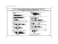
EXAMPLE: FLOW MAX GROUPFIGURE 1-1Technical Bulletin 020 Sheet 3 of 183910-B Royal Avenue Tel: (805) 527-4498Simi Valley, CA 93063 Fax: (805) 527-2813
(2.0) CONDITIONS:SECTION TWOCentral System Users, NON-Flow Max Group, NO ET Tracker01. PANEL REPLACEMENT FOR A SUBMASTER OR SATELLITE (NON-SUBMASTER): NON-FLOW MAX GROUP, NO ET TRACKER CONNECTED.02. UNLESS OTHERWISE SPECIFIED, ALL REFERENCES WILL BE MADE TO THE DX2 USER’SMANUAL. KEY PRESS SEQUENCES FOR THE DX2 CONTROLLER WILL BE THE SAME FORTHE EVOLUTION CONTROLLER.(2.1) PRIOR TO PANEL REMOVAL:01. AT THE CENTRAL PC. With a Central System configuration, prior to removing a controller MainPanel for replacement, it is important to upload the existing data to the Central PC, IF THECENTRAL PC HAS COMMUNICATIONS WITH THE CONTROLLER BEING SERVICED.This will insure the most current information resides at Central. For the controller in questionupload STATISTICS, PROGRAMS, CURRENT LIMITS, and FLOW LIMITS. WARNING:IF A SYSTEM USES BASIC ET, DO NOT UPLOAD PROGRAMINFORMATION FROM THE FIELD CONTROLLER. THE ADJUSTEDSTATION RUN TIME WILL BECOME THE “BASE” RUN TIME IFUPLOADED.02. AT THE CENTRAL PC. Place the Satellite OFF-LINE.03. AT THE CONTROLLER.‣ Is it a SUBMASTER? If so, make note of the Satellite Address. The address number isalternately displayed on the base screen with the program number.‣ Is a FLOW METER(s) CONNECTED? If so, make note of the K and Offset values. Keypresses: QUIT, F1, F5, F5, F2, [F1 = Flow meter 1, F2 = Flow meter 2].Reference DX2 User’s Manual page 4-51.‣ Is a MOISTURE SENSOR(s) CONNECTED? If so, make note of the Trip Point(s). Keypresses: QUIT, F1, F5, F5, F1, [F1 = Review M sensors]. Reference DX2 User’sManual page 4-46.(2.2) MAIN PANEL REMOVAL:01. AT THE CONTROLLER. POWER OFF THE CONTROLLER.02. Remove the four screws that hold the Main Panel assembly in place.03. Note the cable connections and orientation. The cable connections are keyed to minimize error.Gently remove all cables from the Main Panel Assembly and remove the board.(2.3) MAIN PANEL INSTALLATION:01. AT THE CONTROLLER. With controller power off, place Main Panel into enclosure. Do NOTinsert the four screws at this time.02. Carefully connect the cables to the appropriate Main Panel mating connectors.Technical Bulletin 020 Sheet 4 of 183910-B Royal Avenue Tel: (805) 527-4498Simi Valley, CA 93063 Fax: (805) 527-2813
03. Secure the Main Panel in place with the four mounting screws.04. Turn controller power on. The Main Panel will chirp once and the LANGUAGE (Start-upInitialization) options are displayed. Follow the screen prompts.‣ It may be necessary to adjust the contrast in the display by using the DARK and LIGHT frontpanel keys.‣ LANGUAGE options will only be displayed if the controller RAM has been zeroed out;otherwise the BASE SCREEN will be displayed.05. IS THE CONTROLLER A SUBMASTER? Address the controller to act as a SUBMASTER, thekey presses are: QUIT , F1, F5, F4, F4, [F2 = Acts as Submaster]. Make theappropriate selection [F1 = Radio/Wire, F2 = Phone, F3 = Trunk], then enter thedesired address number. Reference DX2 User’s Manual page 4-43.06. IS THE CONTROLLER A NOT A SUBMASTER? The Satellite will self address whencommunication with the SUBMASTER is established. The satellite address will then be displayedon the base screen. Reference DX2 User’s Manual page 4-43.07. Is a FLOW METER(s) CONNECTED? If so, enter the K and Offset values. Key presses:QUIT, F1, F5, F5, F2, [F1 = Flow meter 1, F2 = Flow meter 2]. Reference DX2User’s Manual page 4-51.08. Is a MOISTURE SENSOR(s) CONNECTED? If so, enter the Trip Point(s). Key presses:QUIT, F1, F5, F5, F1, [F1 = Review M sensors]. Reference DX2 User’s Manual page4-46.09. AT THE CENTRAL PC. Place the controller in question ON-LINE.10. AT THE CENTRAL PC. For the controller in question SET SATELLITE TIME AND NAME.11. AT THE CENTRAL PC. For the controller in question download PROGRAMS, CURRENTLIMITS, and FLOW LIMITS.12. AT THE CENTRAL PC. If the controller serviced is connected to a weather station, theRAIN and WIND limits must be downloaded to the controller.Technical Bulletin 020 Sheet 5 of 183910-B Royal Avenue Tel: (805) 527-4498Simi Valley, CA 93063 Fax: (805) 527-2813
(3.0) CONDITIONS:SECTION THREECentral System Users, Flow Max Group, and/or ET Tracker01. PANEL REPLACEMENT FOR A SUBMASTER OR SATELLITE (NON-SUBMASTER): FLOWMAX GROUP AND/OR ET TRACKER CONNECTED.02. FOR A DETAILED DESCRIPTION OF FLOW MAX, REFER TO DX2 USER’S MANUALAPPENDIX F.03. UNLESS OTHERWISE SPECIFIED, ALL REFERENCES WILL BE MADE TO THE DX2 USER’SMANUAL. KEY PRESS SEQUENCES FOR THE DX2 CONTROLLER WILL BE THE SAME FORTHE EVOLUTION CONTROLLER.(3.1) PRIOR TO PANEL REMOVAL:01. AT THE CENTRAL PC. With a Central System configuration, prior to removing a controller MainPanel for replacement, it is important to upload the existing data to the Central PC, IF THECENTRAL PC HAS COMMUNICATIONS WITH THE CONTROLLER BEING SERVICED.This will insure the most current information resides at Central. For the controller in questionupload STATISTICS, PROGRAMS, CURRENT LIMITS, and FLOW LIMITS. WARNING: IF A SYSTEM USES BASIC ET, DO NOT UPLOAD PROGRAM INFORMATIONFROM THE FIELD CONTROLLER. THE ADJUSTED STATION RUN TIME WILL BECOMETHE “BASE” RUN TIME IF UPLOADED.02. AT THE CENTRAL PC. Place the Satellite OFF-LINE.03. AT THE CONTROLLER.‣ Is it a SUBMASTER? If so, make note of the Satellite Address. The address number isalternately displayed on the base screen with the program number.‣ Is it part of a FLOW MAX GROUP? This will require clarification from the end user. Refer toFIGURES 3-1 and 3-2 of this document for guidance. Make note of which devices are shared and which controller the shared devices areconnected to. Key presses: QUIT, F1, F5, F4, F4, F3, [F1 = Share Flow, Pump& MV]. Take note, is Flow Meter 1 connected to this Clock? Press the Down ArrowKey to view and note which devices are connected to this Clock.‣ Is a FLOW METER(s) CONNECTED? If so, make note of the K and Offset values. Keypresses: QUIT, F1, F5, F5, F2, [F1 = Flow meter 1, F2 = Flow meter 2]. Reference DX2User’s Manual page 4-51.‣ Is a MOISTURE SENSOR(s) CONNECTED? If so, make note of the Trip Point(s). Keypresses: QUIT, F1, F5, F5, F1, [F1 = Review M sensors]. Reference DX2 User’s Manualpage 4-46.Technical Bulletin 020 Sheet 6 of 183910-B Royal Avenue Tel: (805) 527-4498Simi Valley, CA 93063 Fax: (805) 527-2813
EXAMPLE: FLOW MAX WORKSHEETFIGURE 3-1Technical Bulletin 020 Sheet 7 of 183910-B Royal Avenue Tel: (805) 527-4498Simi Valley, CA 93063 Fax: (805) 527-2813
FLOW MAX WORKSHEETFIGURE 3-2Technical Bulletin 020 Sheet 8 of 183910-B Royal Avenue Tel: (805) 527-4498Simi Valley, CA 93063 Fax: (805) 527-2813
(3.2) MAIN PANEL REMOVAL:01. AT THE CONTROLLER. POWER OFF THE CONTROLLER.02. Remove the four screws that hold the Main Panel assembly in place.03. Note the cable connections and orientation. The cable connections are keyed to minimize error.Gently remove all cables from the Main Panel Assembly and remove the board.(3.3) MAIN PANEL INSTALLATION:01. AT THE CONTROLLER. With controller power off, place Main Panel into enclosure. Do NOTinsert the four screws at this time.02. Carefully connect the cables to the appropriate Main Panel mating connectors.03. Secure the Main Panel in place with the four mounting screws.04. Turn controller power on. The Main Panel will chirp once and the LANGUAGE options will bedisplayed, follow the screen prompts.‣ It may be necessary to adjust the contrast in the display by using the DARK and LIGHT frontpanel keys.‣ LANGUAGE options will only be displayed if the controller RAM has been zeroed out;otherwise the BASE SCREEN will be displayed.05. IS THE CONTROLLER A SUBMASTER? Address the controller to act as a SUBMASTER, thekey presses are: QUIT, F1, F5, F4, F4, [F2 = Acts as Submaster]. Make theappropriate selection [F1 = Radio/Wire, F2 = Phone, F3 = Trunk], then enter thedesired address number. Reference DX2 User’s Manual page 4-43.06. IS THE CONTROLLER NOT A SUBMASTER? The Satellite will self address whencommunication with the SUBMASTER is established. The satellite address will then be displayedon the base screen. Reference DX2 User’s Manual page 4-43.07. Is a FLOW METER(s) CONNECTED? If so, enter the K and Offset values. Key presses:QUIT, F1, F5, F5, F2, [F1 = Flow meter 1, F2 = Flow meter 2]. Reference DX2User’s Manual page 4-51.‣ If Flow Meter 1and 2 are NOT connected, set K and Offset values to zero. If Flow Meter 1 or 2 are used, and connected to a controller other than theSUBMASTER, the K and Offsets MUST be entered at BOTH the controller where theflow meter is physically connected AND the Submaster controller. All Flow Meter Kand Offset values of both Flow Meter 1 and Flow Meter 2 (if used) must be enteredat the Submaster <strong>Control</strong>ler, regardless of physical connection location.08. Is an ET TRACKER CONNECTED? If so, Flow Meter 2 MUST BE ENABLED (connected to thisclock = yes). Flow Meter 2, K and Offset values, MUST BE SET TO ZERO. This will enable theport to read the ET Tracker. Key presses: QUIT, F1, F5, F5, F2, [F2 = Flow meter 2].Reference DX2 User’s Manual page 4-51.Technical Bulletin 020 Sheet 9 of 183910-B Royal Avenue Tel: (805) 527-4498Simi Valley, CA 93063 Fax: (805) 527-2813
09. A <strong>Control</strong>ler that is part of a FLOW MAX GROUP MUST BE INITIALIZED AS A FLOW MAXPARTICIPANT.Is it a SUBMASTER? (Reference DX2 User’s Manual page F-13).‣ Select the devices that are to be shared in the Flow Max operation. Key presses:QUIT, F1, F5, F4, F4, F3, [F1 = SHARE FLOW, PUMP & MV].Is it a SATELLITE (Non-Submaster)? (Reference DX2 User’s Manual page F-21).‣ If it is a NON-Flow Max Participant, no Flow Max set-up is required. To assure orconfirm the controller is not in Flow Max, set it in the “NORMAL MODE” with Keypresses: QUIT, F1, F5, F4, F4, F3, [F3 = Normal Mode]. The Base Screenreturns.‣ If it is a Flow Max Participant? Select the devices that are to be shared in the FlowMax operation. Key presses: QUIT, F1, F5, F4, F4, F3, [F1 Share Flow, Pump& MV].10. Is a MOISTURE SENSOR(s) CONNECTED? If so, enter the Trip Point(s). Key presses:QUIT, F1, F5, F5, F1, [F1 = Review M sensors]. Reference DX2 User’s Manual page4-46.11. AT THE CENTRAL PC.‣ Place the controller in question ON-LINE.‣ For the controller in question SET SATELLITE TIME AND NAME.‣ For the controller in question download PROGRAMS, CURRENT LIMITS, and FLOW LIMITS.‣ AT THE CENTRAL PC. If the controller serviced is connected to a weather station,the RAIN and WIND limits must be downloaded to the controller.Technical Bulletin 020 Sheet 10 of 183910-B Royal Avenue Tel: (805) 527-4498Simi Valley, CA 93063 Fax: (805) 527-2813
(4.0) CONDITIONS:SECTION FOURNON-Central System Users, NON-Flow Max, NO ET Tracker01. PANEL REPLACEMENT FOR A STAND ALONE CONTROLLER: NO FLOW MAX GROUP ANDNO ET TRACKER CONNECTED.02. UNLESS OTHERWISE SPECIFIED, ALL REFERENCES WILL BE MADE TO THE DX2 USER’SMANUAL. KEY PRESS SEQUENCES FOR THE DX2 CONTROLLER WILL BE THE SAME FORTHE EVOLUTION CONTROLLER.03. REFER TO DX2 USERS MANUAL PAGES 4-1 THROUGH 4-6 FOR SETUP OPTIONS ANDSYSTEM DEFAULTS.(4.1) PRIOR TO PANEL REMOVAL:01. AT THE CONTROLLER.‣ If necessary, review and note all programs.‣ Is a FLOW METER(s) CONNECTED? If so, make note of the K and Offset values. Keypresses: QUIT, F1, F5, F5, F2, [F1 = Flow meter 1, F2 = Flow meter 2].Reference DX2 User’s Manual page 4-51.‣ Is a MOISTURE SENSOR(s) CONNECTED? If so, make note of the Trip Point(s). Keypresses: QUIT, F1, F5, F5, F1, [F1 = Review M sensors]. Reference DX2 User’sManual page 4-46.(4.2) MAIN PANEL REMOVAL:01. AT THE CONTROLLER. POWER OFF THE CONTROLLER.02. Remove the four screws that hold the Main Panel assembly in place.03. Note the cable connections and orientation. The cable connections are keyed to minimize error.Gently remove all cables from the Main Panel Assembly and remove the board.(4.3) MAIN PANEL INSTALLATION:01. AT THE CONTROLLER. With controller power off, place Main Panel into enclosure. Do NOTinsert the four screws at this time.02. Carefully connect the cables to the appropriate Main Panel mating connectors.03. Secure the Main Panel in place with the four mounting screws.04. Turn controller power on. The Main Panel will chirp once and the LANGUAGE options will bedisplayed, follow the screen prompts.‣ It may be necessary to adjust the contrast in the display by using the DARK and LIGHT frontpanel keys.‣ LANGUAGE options will only be displayed if the controller RAM has been zeroed out;otherwise the BASE SCREEN will be displayed.05. Is a FLOW METER(s) CONNECTED? If so, enter the K and Offset values. Key presses:Technical Bulletin 020 Sheet 11 of 183910-B Royal Avenue Tel: (805) 527-4498Simi Valley, CA 93063 Fax: (805) 527-2813
QUIT, F1, F5, F5, F2, [F1 = Flow meter 1, F2 = Flow meter 2]. Reference DX2User’s Manual page 4-51.06. Is a MOISTURE SENSOR(s) CONNECTED? If so, enter the Trip Point(s). Key presses:QUIT, F1, F5, F5, F1, [F1 = Review M sensors]. Reference DX2 User’s Manual page4-46.07. ENTER PROGRAM(S) INTO CONTROLLER. This will require clarification from the End User.08. OPTIONAL: If the panel being installed is a temporary loaner while the original is being repaired,it may not be necessary to utilize the electrical or flow check feature. If however the panel beinginstalled is the permanent, both the station electrical and flow values must be manually entered orrelearned and ENABLE the feature. When Flow Sensing is used, Station Flows, Main Line Flowand Unscheduled Flow Allowance must each be entered. DX2 CONTROLLERS. ESTABLISHCURRENT and/or FLOW LIMITS. This will require clarification from the End User. Key presses:QUIT, F1, F5, F3, F3, [F1 = RUN AUTO LIMITS, F2 = SET LIMIT (%)].Reference DX2 User’s Manual page 4-28.‣ EVOLUTION CONTROLLERS. Manually set CURRENT and/or FLOW LIMITS for eachstation. Key presses: QUIT, F1, F5, F3, [F1 = ENABLE/DISABLE LIMITCHECKING, F2 = MANUAL LIMITS/STATION SETUP].Technical Bulletin 020 Sheet 12 of 183910-B Royal Avenue Tel: (805) 527-4498Simi Valley, CA 93063 Fax: (805) 527-2813
(5.0) CONDITIONS:SECTION FIVENON-Central System Users, Flow Max, and or ET Tracker01. PANEL REPLACEMENT FOR A SUBMASTER OR SATELLITE (NON-SUBMASTER): FLOWMAX GROUP AND/OR ET TRACKER CONNECTED.02. UNLESS OTHERWISE SPECIFIED, ALL REFERENCES WILL BE MADE TO THE DX2 USER’SMANUAL. KEY PRESS SEQUENCES FOR THE DX2 CONTROLLER WILL BE THE SAME FORTHE EVOLUTION CONTROLLER.03. REFER TO DX2 USERS MANUAL PAGES 4-1 THROUGH 4-6 FOR SETUP OPTIONS ANDSYSTEM DEFAULTS.(5.1) PRIOR TO PANEL REMOVAL:01. AT THE CONTROLLER.‣ Is it a SUBMASTER? If so, make note of the Satellite Address. The address number isalternately displayed on the base screen with the program number.‣ If necessary, review and note all programs.‣ Is it part of a FLOW MAX GROUP? This will require clarification from the end user. Refer toFIGURES 5-1 and 5-2 of this document for guidance. Make note of which devices are shared and which devices are connected to this controller.Key presses: QUIT, F1, F5, F4, F4, F3, [F1 = Share Flow, Pump & MV].Take note, is Flow Meter 1 connected to this Clock? Press the Down Arrow Key to viewand note which devices are connected to this Clock.‣ Is a FLOW METER(s) CONNECTED? If so, make note of the K and Offset values. Keypresses: QUIT, F1, F5, F5, F2, [F1 = Flow meter 1, F2 = Flow meter 2].Reference DX2 User’s Manual page 4-51.‣ Is a MOISTURE SENSOR(s) CONNECTED? If so, make note of the Trip Point(s). Keypresses: QUIT, F1, F5, F5, F1, [F1 = Review M sensors]. Reference DX2 User’sManual page 4-46.(5.2) MAIN PANEL REMOVAL:01. AT THE CONTROLLER. POWER OFF THE CONTROLLER.02. Remove the four screws that hold the Main Panel assembly in place.03. Note the cable connections and orientation. The cable connections are keyed to minimize error.Gently remove all cables from the Main Panel Assembly and remove the board.(5.3) MAIN PANEL INSTALLATION:01. AT THE CONTROLLER. With controller power off, place Main Panel into enclosure. Do NOTinsert the four screws at this time.02. Carefully connect the cables to the appropriate Main Panel mating connectors.Technical Bulletin 020 Sheet 13 of 183910-B Royal Avenue Tel: (805) 527-4498Simi Valley, CA 93063 Fax: (805) 527-2813
03. Secure the Main Panel in place with the four mounting screws.04. Turn controller power on. The Main Panel will chirp once and the LANGUAGE options will bedisplayed, follow the screen prompts.‣ It may be necessary to adjust the contrast in the display by using the DARK and LIGHT frontpanel keys.‣ LANGUAGE options will only be displayed if the controller RAM has been zeroed out;otherwise the BASE SCREEN will be displayed.05. IS THE CONTROLLER A SUBMASTER? Address the controller to act as a SUBMASTER, thekey presses are: QUIT, F1, F5, F4, F4, [F2 = Acts as Submaster]. Make theappropriate selection [F1 = Radio/Wire, F2 = Phone, F3 = Trunk], then enter thedesired address number. Reference DX2 User’s Manual page 4-43.06. IS THE CONTROLLER A SATELLITE (not a Submaster)? No Address setup is required. TheSatellite will self address and the base screen will be displayed. Reference DX2 User’s Manualpage 4-43.07. Is a FLOW METER(s) CONNECTED? If so, enter the K and Offset values. Key presses:QUIT, F1, F5, F5, F2, [F1 = Flow meter 1, F2 = Flow meter 2]. Reference DX2User’s Manual page 4-51.08. Is an ET TRACKER CONNECTED? If so, Flow Meter 2 MUST BE ENABLED (connected to thisclock = yes). Flow Meter 2, K and Offset values, MUST BE SET TO ZERO. This will enable theport to read the ET Tracker. Key presses: QUIT, F1, F5, F5, F2, [F2 = Flow meter 2].Reference DX2 User’s Manual page 4-51.09. Is the <strong>Control</strong>ler part of a FLOW MAX GROUP? This will require clarification from the End User.‣ Is it a SUBMASTER? (Reference DX2 User’s Manual page F-13).‣ Select the devices that are to be shared in the Flow Max operation. Key presses:QUIT, F1, F5, F4, F4, F3, [F1 = SHARE FLOW, PUMP & MV].‣ Set Flow Meter K and Offset values All Flow Meter K and Offset values of both Flow Meter 1 and Flow Meter 2 (if used)must be entered at the Submaster <strong>Control</strong>ler, regardless of physical connectionlocation. The values must also be entered at the Satellite <strong>Control</strong>lers that arephysically connected to Flow Meter 1 or 2.‣ Is it a SATELLITE? (Reference DX2 User’s Manual page F-21).‣ If it is a NON-Flow Max Participant, no Flow Max set-up is required. To assure orconfirm the controller is not in Flow Max, set it in the “NORMAL MODE” with Keypresses: QUIT, F1, F5, F4, F4, F3, [F3 = Normal Mode]. The Base Screenreturns.‣ Is it a Participant? Select the devices that are to be shared in the Flow Max operation.Key presses: QUIT, F1, F5, F4, F4, F3, [F1 Share Flow, Pump & MV].10. Is a MOISTURE SENSOR(s) CONNECTED? If so, enter the Trip Point(s). Key presses:QUIT, F1, F5, F5, F1, [F1 = Review M sensors]. Reference DX2 User’s Manual page4-46.11. ENTER PROGRAM(S) INTO CONTROLLER. This will require clarification from the End User.12. OPTIONAL: If the panel being installed is a temporary loaner while the original is being repaired,Technical Bulletin 020 Sheet 14 of 183910-B Royal Avenue Tel: (805) 527-4498Simi Valley, CA 93063 Fax: (805) 527-2813
it may not be necessary to utilize the electrical or flow check feature. If however the panel beinginstalled is the permanent, both the station electrical and flow values must be manually entered orrelearned and ENABLE the feature. When Flow Sensing is used, Station Flows, Main Line Flowand Unscheduled Flow Allowance must each be entered. DX2 CONTROLLERS. ESTABLISHCURRENT and/or FLOW LIMITS. This will require clarification from the End User. Key presses:QUIT, F1, F5, F3, F3, [F1 = RUN AUTO LIMITS, F2 = SET LIMIT (%)].Reference DX2 User’s Manual page 4-28.‣ EVOLUTION CONTROLLERS. Manually set CURRENT and/or FLOW LIMITS for eachstation. Key presses: QUIT, F1, F5, F3, [F1 = ENABLE/DISABLE LIMITCHECKING, F2 = MANUAL LIMITS/STATION SETUP].Technical Bulletin 020 Sheet 15 of 183910-B Royal Avenue Tel: (805) 527-4498Simi Valley, CA 93063 Fax: (805) 527-2813
EXAMPLE: FLOW MAX WORKSHEETFIGURE 5-1Technical Bulletin 020 Sheet 16 of 183910-B Royal Avenue Tel: (805) 527-4498Simi Valley, CA 93063 Fax: (805) 527-2813
FLOW MAX WORKSHEETFIGURE 5-2Technical Bulletin 020 Sheet 17 of 183910-B Royal Avenue Tel: (805) 527-4498Simi Valley, CA 93063 Fax: (805) 527-2813
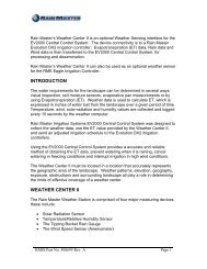
SECTION SIXCable Connections, Evolution and DX2 <strong>Control</strong>lersDX2 <strong>Control</strong>ler All fourconnectors arekeyed. 1 “RED” – MainPanel to <strong>Master</strong>Valve Board. 2 “WHITE” –Main Panel toOutput Board. 3 “FLOW” –Optional,Sensor Boardto SensorTerminalBoard.1234 4 “COMM” –Main Panel toCommHardwireBoard.Evolution<strong>Control</strong>ler All fourconnectors arekeyed. 1 “COMM” -Main Panel toSatellite Board. 2 – “STATIONS”Main Panel toOutput Board,1-24. 3 “FLOW” –Optional, SensorBoard to SensorTerminal Board. 4 “STATIONS” –Main Panel toOutput Board,25-48.Pin 1, Stripe1234END OF BULLETINTechnical Bulletin 020 Sheet 18 of 183910-B Royal Avenue Tel: (805) 527-4498Simi Valley, CA 93063 Fax: (805) 527-2813