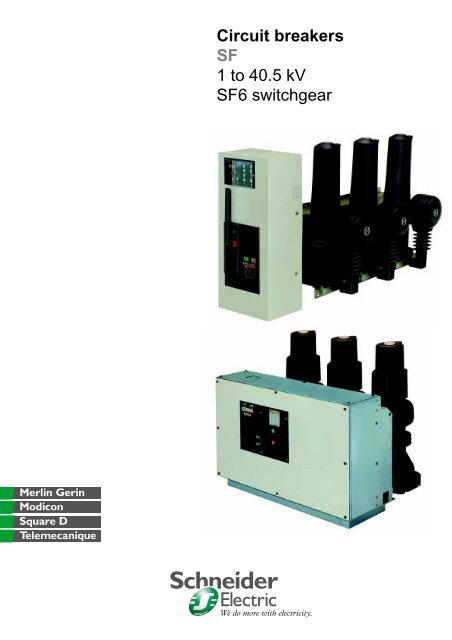
Circuit breakers SF 1 to 40.5 kV SF6 switchgear - Schneider Electric ...
Circuit breakers SF 1 to 40.5 kV SF6 switchgear - Schneider Electric ...
Circuit breakers SF 1 to 40.5 kV SF6 switchgear - Schneider Electric ...

You also want an ePaper? Increase the reach of your titles
YUMPU automatically turns print PDFs into web optimized ePapers that Google loves.
<strong>Circuit</strong> <strong>breakers</strong><strong>SF</strong>1 <strong>to</strong> <strong>40.5</strong> <strong>kV</strong><strong>SF</strong>6 <strong>switchgear</strong>We do more with electricity.
<strong>SF</strong>circuit <strong>breakers</strong>1 <strong>to</strong> <strong>40.5</strong> <strong>kV</strong>contentspage<strong>SF</strong>6 gasthe universal technology 2for medium voltagethe <strong>switchgear</strong> manufacturers’ gas 3breaking techniqueau<strong>to</strong>-compression technique 4operating 5generala high-performance 6and reliable rangecertified quality: ISO 9001 7electrical characteristics 8description<strong>SF</strong>1 circuit breaker 10<strong>SF</strong>set circuit breaker 11<strong>SF</strong>2, I<strong>SF</strong>2, circuit breaker 12auxiliaries 13operating mechanismsand diagrams<strong>SF</strong>1/<strong>SF</strong>set circuit breaker 14<strong>SF</strong>2 circuit breaker 16protection and control/moni<strong>to</strong>ringprotection units 18VIP13 protection unit 20VIP17 protection unit 21VIP200/VIP201 control units 22time/current curves 25dimensions<strong>SF</strong>1, <strong>SF</strong>set 28<strong>SF</strong>2, I<strong>SF</strong>2 30identification of unitsexamples of rating plates, 31inspection shee<strong>to</strong>rder information 32<strong>Schneider</strong> <strong>Electric</strong>GammeAC0415EN_001_007.fm/
0<strong>SF</strong> circuit <strong>breakers</strong>, 1 <strong>to</strong> <strong>40.5</strong> <strong>kV</strong><strong>SF</strong>6 gasthe universal technology for medium voltagemastering difficult currentsThe absence of overvoltages is one of thenumerous advantages of the <strong>SF</strong>6 breakingtechnique, eliminating the need for arrestingdevices <strong>to</strong> reduce switching surges.Short-circuit currentsThe short duration of the arc in the breakingchamber and the rapid recovery of the <strong>SF</strong>6dielectric properties enable <strong>SF</strong>6 <strong>switchgear</strong><strong>to</strong> break fault currents up <strong>to</strong> 50 kA rms.Capacitive currents<strong>SF</strong>6 <strong>switchgear</strong> does not provoke multiplerestrikes. Capacitive currents (lines,unloaded cables, capaci<strong>to</strong>r banks) cantherefore be interrupted without creatingovervoltages that could damage equipmentconnected <strong>to</strong> the network.Low inductive currentsUsing the <strong>SF</strong>6 breaking technique, thechopping current, resulting from theinstability of the arc at low currents, isreduced <strong>to</strong> a very low level. Thecorresponding overvoltage is thereforeconsiderably reduced <strong>to</strong> a level that cannotdamage equipment.Numerous tests carried out in national andinternational labora<strong>to</strong>ries have shown thatmultiple restrikes (opening) or prestrikes(closing) do not occur with <strong>SF</strong>6 <strong>switchgear</strong>.<strong>SF</strong>6 <strong>switchgear</strong> ensures surge-freebreaking, eliminating successive dielectricbreakdowns and the need for surgearrestingdevices.the experience of a majormanufacturerGiven its pioneer work in the puffer-type <strong>SF</strong>6technique, Merlin Gerin naturally played adecisive role in developing furtherapplications of the technique.Merlin Gerin is <strong>to</strong>day one of the foremostmanufacturers of <strong>SF</strong>6 <strong>switchgear</strong>, with:# more than twenty years of industrialexperience using <strong>SF</strong>6 techniques,# more than 500 000 <strong>switchgear</strong> unitsinstalled around the world,It has developed a wide range of highperformanceand reliable units, operatingfaultlessly on all five continents.The company continuously innovates <strong>to</strong>improve performance levels. In 1989, itintroduced a product based on a newconcept, the <strong>SF</strong>set circuit breaker withintegrated protection functions.<strong>SF</strong>6 <strong>switchgear</strong> is thus capable of meetingthe most demanding requirements of publicand industrial distribution networks worldwide,up <strong>to</strong> <strong>40.5</strong> <strong>kV</strong>.C0415EN_001_007.fm/2Gamme<strong>Schneider</strong> <strong>Electric</strong>
0the <strong>switchgear</strong> manufacturers’ gasFa widely available gassealed pressure systemFF<strong>SF</strong>FFLike all gases in current use, <strong>SF</strong>6 isavailable in all countries of the world.<strong>SF</strong>6 is non-<strong>to</strong>xic.a non-inflammable gas<strong>SF</strong>6 is an inert gas and does not sustaincombustion.a very stable gasThe high stability of <strong>SF</strong>6 gas is due <strong>to</strong> the6 covalent bonds of its molecule.an insulating gasThe dielectric strength of <strong>SF</strong>6 is superior <strong>to</strong>that of most known media, reaching 5 timesthat of air at a pressure of a few tenthsof MPa.a breaking gas<strong>SF</strong>6 is "the" breaking gas offering a numberof advantages:# high capacity for carrying the heatproduced by the arc. The arc is rapidlycooled by convection during arcing;# high radial thermal conduction andhigh electron capturing capacity;when the current passes through zero:5 the <strong>SF</strong>6 permits rapid heat exchange fromthe centre of the arc <strong>to</strong>wards the exterior,5 the fluorine a<strong>to</strong>ms, which are highlyelectro-negative, act as veritable "traps" forelectrons; since it is the electrons which aremainly responsible for electric conduction inthe gas, the gap between the contactsrecovers its initial dielectric strength throughthis electron capture phenomenon at currentzero.anticipated service life:more than 30 yearsThe breaking system is designed <strong>to</strong> operatewithout maintenance for many years with inparticular:# no need for any <strong>SF</strong>6 refilling throughoutthe service life of the unit, thanks <strong>to</strong> <strong>SF</strong>6 gasrecombination after breaking,# no continuous pressure moni<strong>to</strong>ring.All Merlin Gerin <strong>switchgear</strong> is of the sealedpressure system type in accordance with theIEC 56 definition (appendix EE).Enclosures are filled <strong>to</strong> a low relativepressure of 0.05 <strong>to</strong> 0.35 MPa (0.5 <strong>to</strong>3.5 bars).The seal and the for-life lubrication of therotary seals is provided by an oil film.In the MV circuit breaker field, for example,on more than 20 000 <strong>SF</strong>6 <strong>switchgear</strong> unitsinstalled by the French electrical utility(EDF), the annual fault rate related <strong>to</strong> sealproblems is less than 0.05 %.enduranceThe mechanical and electrical endurance ofMerlin Gerin <strong>SF</strong>6 <strong>switchgear</strong> is far abovethat recommended by the IEC.This equipment meets the needs of powernetworks, even those operating under themost severe conditions.very low maintenanceThe electrical contacts, housed in a sealedfor-lifeenclosure, require no specialmaintenance.The operating mechanism requires onlyminimum maintenance at intervalsdepending on the conditions of use.Under normal operating conditions, nopreventive maintenance is required before10 000 operations or 10 years of service.insensitivity <strong>to</strong> theenvironmentIn addition <strong>to</strong> the active parts (for breaking),the sealed enclosure contains the essentialmechanical parts (for mechanicaltransmission).The result is a fully insulated system.Furthermore, the long creepage distances ofthe insulated enclosures contribute <strong>to</strong> highinsensitivity <strong>to</strong> the outside environment.<strong>Schneider</strong> <strong>Electric</strong>GammeAC0415EN_001_007.fm/
0<strong>SF</strong> circuit <strong>breakers</strong>, 1 <strong>to</strong> <strong>40.5</strong> <strong>kV</strong>breaking techniqueau<strong>to</strong>-compression technique1 Upper current terminal. pole-unit description12 Insulating enclosure.3 Fixed main contact.24 Fixed arcing contact.5 Moving arcing contact.6 Insulating nozzle.7 Moving main contact.8 Moving pis<strong>to</strong>n.9 Pressure chamber.310 Lower current terminal.11 Connecting rod.12 Crank.4 13 Sealing system.5 14 Shaft.6 15 Molecular sieve.7 16 Bot<strong>to</strong>m cover.8910111213141516The <strong>SF</strong> pole unit consists of:# a main circuit with:5 upper current terminal (1),5 fixed main contact with self-wiping blades(3),5 moving main contact (7),5 lower current terminal (10);# a breaking circuit with:5 fixed arcing contact (4),5 moving arcing contact (5);# an au<strong>to</strong>-compression system with:5 pressure chamber (9),5 moving pis<strong>to</strong>n (8),5 insulating nozzle (6);# a transmission mechanism with:5 shaft (14),5 crank (12),5 connecting rod (11);# a sealing system (13) of the "sealedpressure system" type according <strong>to</strong> thedefinition in IEC 56 appendix EE;# an insulating enclosure (2) containing allthe active components, including:5 <strong>SF</strong>6 at low relative internal pressure,5 molecular sieve (15),5 bot<strong>to</strong>m cover (16).principleSimplicityThe movement of the arcing contactscompresses a small volume of gas behind apis<strong>to</strong>n. The compressed gas is trapped andcannot escape between the arcing contactsuntil they begin <strong>to</strong> separate.This pre-compression stage produces aninstantaneous difference in pressure makingit possible <strong>to</strong> inject the gas by forcedconvection.EfficiencyInjection of a small quantity of gas betweenthe contacts suffices <strong>to</strong> “ smother ” the arcby electron capture. This technique breakslow currents and short-circuit currents withequal effectiveness.Clogging effectDuring breaking of heavy currents, thecross-section of the arc is equal <strong>to</strong> that ofthe inside of the injection nozzle at fullbreaking capacity, which considerablyreduces the flow of the injected gas. That isthe clogging effect.The phenomenon has two beneficial results:# s<strong>to</strong>rage, before the current passes throughzero, of almost all the compressed gas;# limiting of the arcing energy by the brakingof the moving parts, thus limiting the lengthof the arc.Moreover, during breaking of low currents,the mass flowrate is reduced and breaking issurge-free.C0415EN_001_007.fm/4Gamme<strong>Schneider</strong> <strong>Electric</strong>
0fig. 1operation<strong>SF</strong>6 circuit <strong>breakers</strong> use the <strong>SF</strong>6 au<strong>to</strong>compressiontechnique.The main contacts and the arcing contactsare initially closed (fig. 1).Pre-compression (fig. 2)When the contacts begin <strong>to</strong> open, the pis<strong>to</strong>nslightly compresses the <strong>SF</strong>6 gas in thepressure chamber.The arcing period (fig. 3)The arc then forms between the arcingcontacts. The pis<strong>to</strong>n continues its downwardmovement. A small quantity of gas, directedby the insulating nozzle, is injected on<strong>to</strong> thearc.For the breaking of low currents, the arc iscooled by forced convection.However, for high currents, thermalexpansion transfers the hot gases <strong>to</strong>wardthe cold parts of the pole unit.Due <strong>to</strong> the dielectric properties of <strong>SF</strong>6, thegap between the two arcing contacts issufficient at the first current zero <strong>to</strong>definitively interrupt the current.Sweeping overstroke (fig. 4)The moving parts finish their travel and theinjection of cold gas continues until thecontacts are completely open.fig. 2fig. 3fig. 4<strong>Schneider</strong> <strong>Electric</strong>GammeAC0415EN_001_007.fm/
0<strong>SF</strong> circuit <strong>breakers</strong>, 1 <strong>to</strong> <strong>40.5</strong> <strong>kV</strong>generala high-performance and reliable rangewide choiceProgress and innovation in <strong>SF</strong>6 technologyhas led <strong>to</strong> a number of importantbreakthroughs in the field of MV<strong>switchgear</strong>.The high performance levels and thereliability of Merlin Gerin circuit <strong>breakers</strong> arelargely a result of the remarkable propertiesof <strong>SF</strong>6 gas.The many ways of implementing <strong>SF</strong>6technology have led <strong>to</strong> a wide range of<strong>switchgear</strong> units.flexible installationSmall in size, <strong>SF</strong>6 <strong>switchgear</strong> is available ina number of versions:# basic fixed units;# fixed units on support frames;# withdrawable units (please consult us).Most can be equipped with either front orside operating mechanisms.intelligent and au<strong>to</strong>nomous<strong>SF</strong>1 and <strong>SF</strong>2 circuit <strong>breakers</strong><strong>SF</strong>1 and <strong>SF</strong>2 circuit <strong>breakers</strong> are used withthe standard protection units (Sepam,Statimax).<strong>SF</strong>set circuit <strong>breakers</strong><strong>SF</strong>set circuit <strong>breakers</strong> integrate, in a singleunit, the different functions cus<strong>to</strong>marily foundin separate compartments.They are equipped with a fully au<strong>to</strong>nomousprotection system, operating without anyauxiliary source and including:# a set of current sensors installed on thelower terminal of the pole unit;# a VIP electronic protection unit;# a low-consumption Mi<strong>to</strong>p release.The various types of units available make itpossible <strong>to</strong> implement multifunctionprotection systems.C0415EN_001_007.fm/6Gamme<strong>Schneider</strong> <strong>Electric</strong>
0certified quality: ISO 9001a major advantageIn each of its sites, Merlin Gerin has set up afunctional organisation vested with theresponsibility of verifying quality levels andensuring correct implementation ofstandards.Company procedures are:# uniform throughout all departments;# recognised by numerous cus<strong>to</strong>mers andinspection organisations such as the French<strong>Electric</strong>al Authority, Frama<strong>to</strong>me, SSIA(French Military Procurement Surveillance),General <strong>Electric</strong>, etc.Furthermore, it is the rigorous application ofprocedures that has enabled certification byan independent organisation, the FrenchAssociation for Quality Assurance (AFAQ).The quality system of the MV departmenthas been certified for conformity with theISO 9001 quality assurance standard.severe and systematicinspectionsDuring production, each circuit breakerundergoes routine testing <strong>to</strong> ensure qualityand conformity. The following points arechecked:# pole-unit seals;# mechanical operation of the unit and anyassociated locking systems;# simultaneous closing of contacts;# insulation level at industrial frequency;# resistance of the main circuit;# insulation level of auxiliary circuits;# electrical resistance of the auxiliarycircuits;# operating speed;# operating cycle;# operating times.Results are indicated on the test certificatefor each unit.<strong>Schneider</strong> <strong>Electric</strong>GammeAC0415EN_001_007.fm/
0<strong>SF</strong> circuit <strong>breakers</strong>, 1 <strong>to</strong> <strong>40.5</strong> <strong>kV</strong>general (cont.)electrical characteristicstype <strong>SF</strong>1 circuit breakerCEI 56, VDE 0670, BS 5311, UTE C 64-100/101rated voltage (<strong>kV</strong> 50/60 Hz) 17.5 24 36insulation level <strong>kV</strong> rms 50 Hz-1 min 38 50 70<strong>kV</strong> impulse 1.2/50 µs 95 125 170rated current 400 # # # # #la (A) 630 # # # # # # # # # #1250 # # # # # # # #25003150breaking capacity at (<strong>kV</strong>) : 6 17,5 12.5 20 25Isc (kA rms) 24 12.5 16 20 2536 12.5 20 2540,5making capacity (kA peak) 31.5 50 63 31.5 40 50 63 31.5 50 63short-time withstand current (kA rms-3s) 12.5 20 25 12.5 16 20 25 12.5 20 25capaci<strong>to</strong>r breaking for Ia (A) : 400 280 280 280 280 280 280 280 280 280capacity 630 440 440 440 440 440 440 440 440 440(A) 1250 875 875 875 875 875 875 875 875 87525003150rated operation O-3 min-CO-3 min-CO # # #sequence O-0.3 s-CO-15 s-CO # # #O-0.3 s-CO-3 min-CO # # #approximate operating opening 50 50 50times (ms) breaking 65 65 65closing 70 70 70ANSI C37.04-C37.06-C37.09rated maximum voltage <strong>kV</strong>, 60 Hz 15.5 (2) 25.8 (1) (2) 38 (4)rated voltage range K fac<strong>to</strong>r 1 1 1rated insolation level <strong>kV</strong>, rms. 60 Hz-1 mn 50 60 80<strong>kV</strong>, impulse 1,2/50 µs 110 150 150rated continuous current A 600 # #1200 # # #20003000rated short-circuit current kA, rms. 25 25 25(at rated max <strong>kV</strong>)rated maximum kA, rms 25 25 25symmetrical interruptingcapability and rated short-time currentclosing and kA, crest 68 68 68latching capability(2.7 K times rated short-circuit current)rated interrupting time cycles 60 Hz 5 5 5rating operation CO-15 s-CO # # #sequence(1) Please consult us.(2) This values are valid for outdoor installations.(3) Above 24 <strong>kV</strong>, the <strong>SF</strong>set is equipped with conventional current transformers.(4) Indoor installations.(5) Interphase barriers.(6) Only in fix installations.C0415EN_008_009.fm/8Gamme<strong>Schneider</strong> <strong>Electric</strong>
<strong>SF</strong>set <strong>SF</strong>2 circuit breaker I<strong>SF</strong>2 switchcircuit breaker with integrated protection unit17.5 24 36 (3) 24 36 <strong>40.5</strong> 24 <strong>40.5</strong>38 50 70 50 70 85 50 8595 125 170 125 170 185 125 185 (5)# # # # ## # # # # # # # # # # ## # # # # # # # # ## # # # # # # # ## # (6) Ã#12.5 20 2512.5 16 20 25 12.5 25 31.5 40 31.512.5 25 31.5 4031.5 2531.5 50 63 31.5 40 50 63 31.5 31.5 63 79 100 63 79 100 79 79 6312.5 20 25 12.5 16 20 25 12.5 12.5 25 31.5 40 25 31.5 40 31.5 31.5 25280 280 280 280 280 280 280 280 280 280 280 280440 440 440 440 440 440 440 440 440 440 440 440875 875 875 875 875 875 875 875 875 875 875 8751750 1750 1750 1750 1750 1750 17502200 2200# # # # # # # Ã# ## # # ## # # # # #50 50 50 50 50 5065 65 65 65 65 6570 70 70 70 70 7025.8 (1)(2) 38 (1)(2)1 160 80 80150 200 150# # ## # # ## #25 25 31.5 40 (1)25 25 31.5 40 (1)68 68 85 1085 5 5 5# # # #<strong>Schneider</strong> <strong>Electric</strong>GammeAC0415EN_008_009.fm/
0 <strong>SF</strong>circuit <strong>breakers</strong>, 1 <strong>to</strong> <strong>40.5</strong> <strong>kV</strong>description<strong>SF</strong>1 circuit breakerapplicationThe <strong>SF</strong>1 is a 3-pole MV circuit breaker forindoor installation.It is used primarily for switching andprotection of 1 <strong>to</strong> 36 <strong>kV</strong> public, industrialand commercial distribution networks.All standard protection units (Sepam,Statimax) may be used with the <strong>SF</strong>1 circuitbreaker.Note that it may also be equipped with anintegrated protection system <strong>to</strong> form a fullyau<strong>to</strong>nomous circuit breaker (see the <strong>SF</strong>set).Basic fixed <strong>SF</strong>1technologyThe <strong>SF</strong>1 implements the au<strong>to</strong>-compressiontechnique using <strong>SF</strong>6 gas as the currentinterruption and insulation medium.The <strong>SF</strong>1 is available in three versions:# basic fixed unit;# fixed unit with a support frame;# withdrawable unit (please consult us).Each version can be equipped with anoperating mechanism installed on the rightside, left side or in front.The basic fixed unit comprises:# three independent main poles that aremechanically connected; each comprises:5 an insulating enclosure of the "sealedpressure system" type (in compliance withIEC 56, 1987 edition, appendix EE) forminga hermetic assembly filled with <strong>SF</strong>6 at a lowrelative pressure (0.05 MPa, i.e. 0.5 bars or0.2 MPa depending on systemcharacteristics);5 active parts housed in the insulatingenclosure;# an RI-type s<strong>to</strong>red-energy operatingmechanism (see the "operating mechanism"section);# a front panel with all the controls andindica<strong>to</strong>rs;# upstream and downstream terminals forconnection of the power circuits.The fixed unit with a support framecomprises:# the basic fixed unit described above;# a support frame fitted with:5 rollers for handling and installation;5 lugs for securing <strong>to</strong> the floor.options (1)For each version, options include:# an electrical RI operating mechanism;# a device for locking the circuit breaker inthe open position (via a keylock);# a keylock for the locking option;# a pressure switch for each pole,equipped with an NO contact for continuousmoni<strong>to</strong>ring of the <strong>SF</strong>6 (please consult us);(1) The "operating mechanism" section describes otherspecific auxiliaries.0415EN_010_017.fm/10Gamme<strong>Schneider</strong> <strong>Electric</strong>
0<strong>SF</strong>set circuit breakerBasic fixed <strong>SF</strong>set.Schematic diagram of the <strong>SF</strong>set<strong>SF</strong>1Mi<strong>to</strong>pCSVIP12applicationThe <strong>SF</strong>set is a 3-poles MV circuit breakerfor indoor installation.It is used primarily for switching andprotection of 1 <strong>to</strong> 36 <strong>kV</strong> public, industrialand commercial distribution networks.The <strong>SF</strong>set is equipped with an integratedprotection system that is fully au<strong>to</strong>nomous(with VIP type protection unit), operatingwithout an auxiliary power supply (see the“protection andcontrol/moni<strong>to</strong>ring” section).technologyThe <strong>SF</strong>set implements the au<strong>to</strong>compressiontechnique using <strong>SF</strong>6 gas asthe current interruption and insulationmedium.The <strong>SF</strong>set is available in two versions:# basic fixed unit;# fixed unit with a support frame.Each version can be equipped with anoperating mechanism installed on the rightside, left side or in front.The basic fixed unit comprises:# a <strong>SF</strong>1 circuit breaker;# an au<strong>to</strong>nomous protection systemcomprising:5 2 or 3 functional current sensors (2)installed on the lower current terminals ofthe pole units;5 a VIP electronic protection unit installedon the operating mechanism enclosure,5 a "Mi<strong>to</strong>p" low-consumption openingrelease installed on the circuit breaker.The fixed unit with a support framecomprises:# the basic fixed unit described above;# a support frame fitted with:5 rollers for handling and installation,5 lugs for securing <strong>to</strong> the floor.options (1)For each version, options include:# a device for locking the circuit breaker inthe open position (via a keylock);# a keylock for the locking option;# a pressure switch for each pole,equipped with an NO contact for continuousmoni<strong>to</strong>ring of the <strong>SF</strong>6 (please consult us).(1) The "operating mechanism" section describes otherspecific auxiliaries.(2) For voltages 24 <strong>kV</strong>, units are fitted with conventionalcurrent transformers (please consult us).<strong>Schneider</strong> <strong>Electric</strong>GammeAC0415EN_010_017.fm/1
0<strong>SF</strong> circuit <strong>breakers</strong>, 1 <strong>to</strong> <strong>40.5</strong> <strong>kV</strong>description (cont.)<strong>SF</strong>2, I<strong>SF</strong>2 circuit breakerapplicationThe <strong>SF</strong>2 is a 3-pole MV circuit breaker forindoor installation.It is used primarily for switching andprotection of 24 <strong>to</strong> 38 <strong>kV</strong> public andindustrial distribution networks.All standard protection units (Sepam,Statimax) may be used with the <strong>SF</strong>2(please consult us).special applicationI<strong>SF</strong>2 is a 3-pole indoor switch-circuitbreaker. Designed <strong>to</strong> withstand highoperating rates, it is especially suitable forthe control of electric furnaces. It can switch50.000 times with a maintenance program <strong>to</strong>be defined in accordance with operatingconditions.Fixed <strong>SF</strong>2 with support frame.technologyThe <strong>SF</strong>2 implements the au<strong>to</strong>-compressiontechnique using <strong>SF</strong>6 gas as the currentinterruption and insulation medium.The <strong>SF</strong>2 is available in three versions:# basic fixed unit;# fixed unit with a support frame;# withdrawable unit (please consult us).The basic fixed unit comprises:# three independent main poles that aremechanically connected. Each comprises:5 an insulating enclosure of the "sealedpressure system" type (in compliance withIEC 56, 1987 edition, appendix EE) forminga hermetic assembly filled with <strong>SF</strong>6 at a lowrelative pressure (0.35 MPa, i.e. 3.5 bars);5 active parts housed in the insulatingenclosure;# an GMh-type s<strong>to</strong>red-energy operatingmechanism (see the "operating mechanism"section);# a front panel with all the controls andindica<strong>to</strong>rs;# upstream and downstream terminals forconnection of the power circuits.The fixed unit with a support framecomprises:# the basic fixed unit described above;# a support frame fitted with:5 rollers for handling and installation,5 lugs for securing <strong>to</strong> the floor.options (1)For the basic fixed unit or the fixed unitwith support frame, options include:# a device for locking the circuit breaker inthe open position (via a keylock);# a keylock for the locking option;# a pressure switch for each pole, forcontinuous moni<strong>to</strong>ring of the <strong>SF</strong>6.1) The "operating mechanism" section describes otherspecific auxiliaries.0415EN_010_017.fm/12Gamme<strong>Schneider</strong> <strong>Electric</strong>
0auxiliariesSingle shunt opening releasefor <strong>SF</strong>1, <strong>SF</strong>set and <strong>SF</strong>2.Auxiliary contact blockfor <strong>SF</strong>1, <strong>SF</strong>set and <strong>SF</strong>2.Double shunt opening releasefor <strong>SF</strong>1, <strong>SF</strong>set and <strong>SF</strong>2.Auxiliary contact blockfor <strong>SF</strong>2.Undervoltage opening releasefor <strong>SF</strong>1, <strong>SF</strong>set and <strong>SF</strong>2."End of charging" and "Operating mechanism charged"auxiliary contact block for <strong>SF</strong>1, <strong>SF</strong>set and <strong>SF</strong>2."Mi<strong>to</strong>p" opening release for <strong>SF</strong>2.<strong>Schneider</strong> <strong>Electric</strong>GammeAC0415EN_010_017.fm/1
0<strong>SF</strong> circuit <strong>breakers</strong>, 1 <strong>to</strong> <strong>40.5</strong> <strong>kV</strong>operating mechanisms and diagrams<strong>SF</strong>1 and <strong>SF</strong>set circuit <strong>breakers</strong><strong>Electric</strong>al RI operating mechanism<strong>SF</strong>1 and <strong>SF</strong>set circuit <strong>breakers</strong> are actuatedby an RI operating mechanism that ensuresoperating speeds (opening and closing)independent of opera<strong>to</strong>r action.When equipped with an electrical operatingmechanism, the circuit breaker can take onremote control functions and implementreclosing cycles.manual RI operatingmechanismThe basic version of the circuit breakercomes with a manual RI operatingmechanism comprising:# a s<strong>to</strong>red-energy mechanism (springtype) that s<strong>to</strong>res the energy required <strong>to</strong> closeand open the contacts;# a spring charging system using a built-inlever;# a mechanical "opening/closing"actuated by two pushbut<strong>to</strong>ns on the frontpanel;# an electrical "opening" system includingan opening release (2) ;# an "operating mechanism charged"indication contact;# an "end of charging" contact;# a block with auxiliary contacts (3) ;# a black/white mechanical "open/closed"position indica<strong>to</strong>r;# a terminal block for connection of externalauxiliary circuits;# a cover <strong>to</strong> protect the operatingmechanism.electrical RI operatingmechanismThe electrical RI operating mechanism,available on request, is made up of themanual RI operating mechanism with thefollowing equipment added in the fac<strong>to</strong>ry:# an electrical "closing" system with aclosing release and an anti-pumping relay;# an electrical spring charging device(mo<strong>to</strong>r-driven) that au<strong>to</strong>matically rechargesthe mechanism as soon as the contacts areclosed;# an operations counter.options (1)The following options are available for themanual RI operating mechanism:# an electrical "closing" system includinga closing release;# an operations counter;# the common auxiliaries (see below).The following common auxiliaries areavailable for both teh manual and electricalRI operating mechanism:# an additional opening release (2) (seecombination possibilities below);# for the undervoltage release:5 a mechanical time delay for opening,adjustable from 0 <strong>to</strong> 3 seconds,5 a mechanism enabling the closing of thecircuit breaker in the event of a circuitbreaker supplied by a "downstream" voltage,# a momentary contact <strong>to</strong> indicate trippingby the "Mi<strong>to</strong>p" release;# a green/red mechanical position indica<strong>to</strong>r(instead of black/white).Auxiliaries: combination possibilities (4)RI operating mechanism electrical closing opening releases availableand auxiliary contacts spring release shunt under- overcurrent Mi<strong>to</strong>p contacts (3)charging single double voltage single double NC NO CHGpower voltage AC (V) 50 Hz 48 - 110 - 220 - 230supply 60 Hz 120 - 240DC (V) 24 - 48 - 110 - 125 - 220current AC (A) 2 à 5 2 à 5consumption AC (VA) 390 180 180 2 x 180 120 120DC (W) 390 65 65 2 x 65 160 15 15combinable auxiliary # 1 # 1 # 1 # 1 5 4 1types and quantities (4) or # 1 # 1 # 1 # 1 5 3 1for <strong>SF</strong>1 and <strong>SF</strong>set or # 1 # 1 # 1 # 1 5 5 1or # 1 # 1 # 1 # 1 5 5 1or # 1 # 1 # 1 # 1 5 4 1additional combination # 1 # 1 # 1 # 1 5 4 1possibilities or # 1 # 1 # 1 # 1 5 4 1for <strong>SF</strong>1 or # 1 # 1 # 1 # 1 5 4 1or # 1 # 1 # 1 # 1 5 3 1or # 1 # 1 # 1 # 1 5 4 1or # 1 # 1 # 1 # 1 5 5 1or # 1 # 1 # 1 # 1 5 5 1or # 1 # 1 # 1 5 5 1rated current (A) 10breaking AC 220V (cos ø ≥ 0,3) 1capacity (A) DC 110/220V (L/R ≤ 0,02 s) 0.3(1) The "description" section provides further information.(2) Single or double shunt release, undervoltage release, or Mi<strong>to</strong>p release (requiring no auxiliary source, necessary for <strong>SF</strong>set).(3) The number of available contacts depends on the options selected.(4) Maximum quantities with the electrical RI operating mechanism.0415EN_010_017.fm/14Gamme<strong>Schneider</strong> <strong>Electric</strong>
JSm1SnMQFSm2Sm3auxiliary wiring diagramRI operating mechanism for <strong>SF</strong>1 (1) J <strong>Circuit</strong> breaker.KN Anti-pumping relay.M Spring charging mo<strong>to</strong>r.M1-M2 End-of-charging contacts.M3 "Operating mechanism charged" indicationcontact.QF <strong>Circuit</strong> breaker auxiliary contacts.SD Fault (Mi<strong>to</strong>p) trip indication momentary contact.SE Trip indication maintained contact.Sm1 Closing pushbut<strong>to</strong>n (outside).Sm2 Opening pushbut<strong>to</strong>n for shunt release (outside).Sm3 Opening pushbut<strong>to</strong>n for undervoltage release(outside).Sn Closing disable contact (outside).SP Pressure-switch contact (please consult us).YF Closing release.Y01-Y02 Shunt opening releases.YM Undervoltage opening release.Mi<strong>to</strong>p Mi<strong>to</strong>p opening release (au<strong>to</strong>nomous).YX1-YX2 Overcurrent opening releases.M1M2SEYFKNY01YMM3Y02SDMi<strong>to</strong>pYX1SPYX2JMQFSnSm1VIPSm2Sm3J <strong>Circuit</strong> breaker.KN Anti-pumping relay.M Spring charging mo<strong>to</strong>r.M1-M2 End-of-charging contacts.M3 "Operating mechanism charged" contact.QF <strong>Circuit</strong> breaker auxiliary contacts.SD Fault (Mi<strong>to</strong>p) trip indication momentary contact.SE Trip indication maintained contact.Sm1 Closing pushbut<strong>to</strong>n (outside).Sm2 Opening pushbut<strong>to</strong>n for shunt release (outside).Sm3 Opening pushbut<strong>to</strong>n for undervoltage release(outside).Sn Closing disable contact (outside).SP Pressure-switch contact (please consult us).YF Closing release.Y01 Shunt opening releases.YM Undervoltage opening release.Mi<strong>to</strong>p Mi<strong>to</strong>p opening release.YX1-YX2 Overcurrent opening releases.M1M2KNSEMi<strong>to</strong>pM3Y01YMSPYFSDYX1YX2(1) Dotted lines represent optional equipment.<strong>Schneider</strong> <strong>Electric</strong>GammeAC0415EN_010_017.fm/1
0<strong>SF</strong> circuit <strong>breakers</strong>, 1 <strong>to</strong> <strong>40.5</strong> <strong>kV</strong>operating mechanisms and diagrams (cont.)<strong>SF</strong>2 circuit <strong>breakers</strong><strong>Electric</strong>al GMh operating mechanism (cover removed)<strong>SF</strong>2 circuit <strong>breakers</strong> are actuated by aGMh operating mechanism that ensuresoperating speeds (opening and closing)independent of opera<strong>to</strong>r action.It can take on remote control functions andimplement reclosing cycles.GMh operating mechanismEvery <strong>SF</strong>2 circuit breaker comes with amanual and electrical GMh operatingmechanism.The manual operating mechanismcomprises:# a s<strong>to</strong>red-energy mechanism (springtype) that s<strong>to</strong>res the energy required <strong>to</strong> closeand open the contacts;# a spring charging system using aremovable lever;# a mechanical "opening/closing" systemactuated by two pushbut<strong>to</strong>ns on the frontpanel;# an electrical "opening" system includingan opening release (2) ;# an "operating mechanism charged"indication contact;# an "end of charging" contact;# a block with auxiliary contacts (3) ;# a black/white mechanical "open/closed"position indica<strong>to</strong>r;# a terminal block for connection ofexternal auxiliary circuits;# a cover <strong>to</strong> protect the operatingmechanism.The electrical GMh operating mechanism ismade up of the manual GMh operatingmechanism plus:# an electrical spring charging device(mo<strong>to</strong>r-driven) that au<strong>to</strong>matically rechargesthe mechanism as soon as the contacts areclosed;# an electrical "closing" system with aclosing release and an anti-pumping relay;# an operations counter.options (1)The following options are available for theGMh operating mechanism:# an additional opening release (2) (seecombination possibilities below);# for the undervoltage release:5 a mechanical opening time delay,adjustable from 0 <strong>to</strong> 3 seconds,5 a mechanism enabling the closing of thecircuit breaker in the event of a circuitbreaker supplied by a "downstream" voltage,# a green/red mechanical position indica<strong>to</strong>r(instead of black/white).Auxiliaries: combination possibilities (4)GMh operating mechanism electrical closing opening release availableand auxiliary contacts spring release shunt under- Mi<strong>to</strong>p contacts (3)charging single double voltage NC NO CHGpower voltage AC (V) 110 - 127 - 220 - 230supply DC (V) 24 - 48 - 110 - 125 - 220consumption AC (VA) 700 120 120 2 x 120 75DC (W) 570 70 70 2 x 70 15combinable auxiliary # 1 # 1 # 1 # 1 5 4 1types and quantities (4) or # 1 # 1 # 1 5 4 1or # 1 # 1 # 1 # 1 5 4 1or # 1 # 1 # 2 5 3 1or # 1 # 1 # 1 # 1 5 3 1or # 1 # 1 # 1 5 3 1or # 1 # 1 # 1 5 5 1or # 1 # 1 # 1 # 1 5 3 1or # 1 # 1 # 1 5 5 1rated current (A) 10breaking AC 220V (pf 4 0.3) 10capacity (A) DC 110/220V (L/R 6 0.01 s) 3(1) The "description" section provides further information.(2) Single or double shunt release, undervoltage release,or Mi<strong>to</strong>p release (requiring no auxiliary source, for Statimaxsystem).(3) The number of available contacts depends on theoptions selected.(4) Maximum quantities with the electrical GMh operatingmechanism.0415EN_010_017.fm/16Gamme<strong>Schneider</strong> <strong>Electric</strong>
0auxiliary wiring diagramJGMh operating mechanism for <strong>SF</strong>2 (1) J <strong>Circuit</strong> breakerSm1SnM1MQFSm2Sm3KNMM1-M2M3QFSESm1Sm2Sm3SnSPYFY01-Y02YMMi<strong>to</strong>pAnti-pumping relaySpring charging mo<strong>to</strong>rEnd-of-charging contacts"Operating mechanism charged" indicationcontact<strong>Circuit</strong> breaker auxiliary contactsMaintained trip indication contactClosing pushbut<strong>to</strong>n (outside)Opening pushbut<strong>to</strong>n for shunt release (outside)Opening pushbut<strong>to</strong>n for undervoltage release(outside)Closing disable contact (outside)Pressure-switch contactClosing releaseShunt opening releasesUndervoltage opening releaseMi<strong>to</strong>p opening release (au<strong>to</strong>nomous)M1SEM2KNY01M3Y02Mi<strong>to</strong>pSPYFYM(1) Dotted lines represent optional equipment.<strong>Schneider</strong> <strong>Electric</strong>GammeAC0415EN_010_017.fm/1
0<strong>SF</strong> circuit <strong>breakers</strong>, 1 <strong>to</strong> <strong>40.5</strong> <strong>kV</strong>protection and control/mono<strong>to</strong>ringProtection unitsVIP protection unit installed on the front panel.for <strong>SF</strong>1 and <strong>SF</strong>2All standard protection units (Sepam,Statimax) may be used with the <strong>SF</strong>1 and<strong>SF</strong>2.For further information, please consult us.for <strong>SF</strong>setThe <strong>SF</strong>set is made up of a <strong>SF</strong>1 circuitbreaker with an added integrated protectionsystem that comprises:■ a VIP protection unit mounted on theoperating mechanism enclosure ;■ a set of current sensors installed on thelower current terminals of the pole units ;■ a low-consumption Mi<strong>to</strong>p release,installed on the operating mechanism.The protection system is fully au<strong>to</strong>nomousand operates without an auxiliary source.VIP protection units are available in threemodels° :■ VIP13, with an adjustable threshold ° ;■ VIP17, with an adjustable threshold,■ VIP200 and VIP201, offeringmicroprocessor-based universal protection.Depending on the model, overcurrent andzera-sequence protection functions areprovided.Current sensorsThe VIP protection units are used inconjunction with functional current sensors.Two interchangeable sensors, Csa andCSb, cover all needs ranging from 10 <strong>to</strong>1250A.252016The various units ofer wide trip-currentsetting ranges and are very stable overtime.OperationSensors supply the protection system with:■ ° current ° information, used by theprotection system ;■ the electrical power required forthe operation of the protection system (VIP unitand ° Mi<strong>to</strong>p ° release).All settings are visible and accessible fromthe front of the circuit breaker.Possible combinationsThe VIP unit mulst be selected taking in<strong>to</strong>account the network characteristicsindicated in the table below.0kA17,5VIP200 - VIP20112,5VIP13 - VIP17 - VIP200 - VIP2012436<strong>kV</strong>The table below indicates the current sensor<strong>to</strong> be used, depending on the current settingIs required on the protection unit.CS-type current sensors.VAP5 test unit.Sensor selectionprotection sensorunit typeprotection unit current setting Is:sensor applicability (1) (for each protection unit rating INC)(A)VIP13 CSa 10 100VIP17 INC = 20CSb 62 630INC = 125VIP200, CSa 20 100VIP201 INC = 2040 100 200INC = 40CSb 125 200 630INC = 125250 630 1250INC = 250test unitsAll VIP protection units are equipped with atest socket for connection of the VAP5-VAP6 test unit (optional).The portables and au<strong>to</strong>nomous VAP5-VAP6units check operation of the protectionsystem.(1) The coloured bars represent the rcommended values,while the shaded bars represent the absolute limits of thevalues thaat may be used.(2) Please consult us.
0VIP 13 protection unitThe VIP13 offers the following protectionfunctions:■ overload protection, with a fixedthreshold and an adjustable time delay;■ short-circuit protection, with anadjustable threshold and instantaneoustripping;■ inverse-time tripping.VIP17 protection unitThe VIP17 offers the following protectionfunctions:■ overload protection, with an adjustablethreshold and an adjustable time delay;■ short-circuit protection, with anadjustable threshold and instantaneoustripping;VIP200 protection unitThe VIP200 offers the following protectionfunctions;■ overload protection, with an adjustable(definite time) or fixed (inverse time)threshold and delayable tripping;■ short-circuit protection, with anadjustable threshold and instantaneoustripping;■ zero-sequence protection, with twoadjustable thresholds and delayable tripping;■ inverse-time curves (4 curves) ordefinite-time curves that may be selected onthe front apnel.The VIP 200 can also be used for localcontrol/moni<strong>to</strong>ring functions:■ tripping indication via a mechanicalindica<strong>to</strong>r (magnetic latching);■ reset of the mechanical indica<strong>to</strong>r;■ self-moni<strong>to</strong>ring with LED indications.VIP201 protection unitThe VIP201 offers the following protectionfunctions:■ overload protection, with and adjustable(definite time) or fixed (inverse-time)threshods and delayable tripping;■ short-circuit protection, with anadjustable thresholds and delayable tripping;■ zero-sequence protection, with twoadjustable threshods and delayable tripping;■ inverse-time curves (4 curves) ordefinite-time curves that may be selected onthe front panel.The VIP201 can also be used for localcontrol/moni<strong>to</strong>ring functions:■ tripping indication via three mechanicalindica<strong>to</strong>rs (magnetic latching);■ reset of the mechanical indica<strong>to</strong>r;■ ammeter with digital display.<strong>Schneider</strong> <strong>Electric</strong>GammeAC0415EN_018_023.fm/1
0<strong>SF</strong> circuit <strong>breakers</strong>, 1 <strong>to</strong> <strong>40.5</strong> <strong>kV</strong>protection and control/mono<strong>to</strong>ring (cont.)VIP13 Protection unit1 2 3vers disjoncteurMi<strong>to</strong>pYD7877Front-plate+5 3A1A2A31A8.1500030.3 t(s).3.61.25 I5IS.5000020A.6 IS.3.6INC1.22.3125A INCtest12A4Inc (a)Csals(A)Csb20 12510 - - -10062 - - - 630A5A6t46A7–1 Test socket (for VAP5-VAP6 tst unit)2 Indication of Inc.3 Is/Inc setting (32 possibilities from 0.5 <strong>to</strong> 5).4 High threshold setting (4 possibilities forI>>/Is from 3 <strong>to</strong> 10).5 Time delay at 10 Is on the inverse time curve(16 possibilities form 0.15 <strong>to</strong> 2.4 s).6 Table indicating the correspondencebetween the characteristic values related <strong>to</strong> thesensor.VIP13 time/current curvetd (s)1 0005002001005020105210,50,20,10,055characteristicsIS setting range10 <strong>to</strong> 630 Alow setting (± 10 %) fixed: 1,2 xthreshold time delay at 10 Is 0,15 <strong>to</strong> 2,4high setting 3 à 10 ISthreshold tripping time fixed: 30 msfor I > 20 ISthermal continuous 6 x INCwithstand 1 speak withstand capacityDefinitions20 kA rms50 kA peakI current in the phase.Inc protection unit current setting.Is protectioon unit current setting.I>> hign threshold current setting.Td tripping time (value read on thecurve for a given setting).<strong>to</strong>tal circuit breaker opening time:td + 32 ms.0,020,010,0050,51 1,223454710203050 60I/IsVIP13 setting exampleConsider an installation with a phase currentI of 18 A, requiring:■ for the fixed low trip threshold: a timedelay of 1.25s at 1.2 Is;■ for the high trip threshold setting: 180 Astep parameters valeursà affichersensor selection for I = 18 A, choose sensor INC = 20 forCSa, with INC = 20setting (2)<strong>to</strong> set IS = 18 A, calculate IS/INC = 0,9IS/INC = 18/20 = 0,9 for setting (3)"phase" protectionlow setting fixed at 1,2 IS, i.e. n.a.thershold1,2 x 18 = 21,6 Acurve always inverse time n.a.timedelayon the curve <strong>to</strong> a "1,25 sdelay at 1,2 IS", read td value= <strong>to</strong> 10 IS, i.e. 0,15 s0,15 sfor setting (5)high setting calculate I>>/IS = 180/18 = 10 I>>/IS = 10thershold for setting (4)resulting curve
0VIP17 Protection unitvers disjoncteurMi<strong>to</strong>p7877Front-plate3 4 5+A8VIP17I>>/Inc I>/Inc t(s)A1+ -A21A3A4A5tA61A7–21 Test socket (for VAP5-VAP6 test unit).2 Indication of Inc.3 High setting I>>/Inc (10 <strong>to</strong> 50 by steps of 2).4 Low setting I>/Inc (0.5 <strong>to</strong> 6.25 by stepsof 0.25).5 Time delay setting t (0.15 <strong>to</strong> 2.1 sec bysteps of 0.05).VIP17time/current curvet (s)1052,12,0521,9510,50,250,20,150,050,020,010,0054 35characteristicsIs setting rangelow setting ± 5 % 0,5 <strong>to</strong> 6,25 Incthershold time delay constant time0,15± 5 % or ± 20 ms <strong>to</strong> 2,1 sechigh setting ± 5 % 10 <strong>to</strong> 50 Incthershold tripping fixed 40 mstimethermal continuous 6 Incwithstand 1s20 KApeak withstandcapacity50 KA peakdéfinitionsI current in the phaseInc protection unit current ratingI> low threshold current settingI>> high threshold current settingtd tripping time<strong>to</strong>tal circuit breaker opening time :td + 32 ms.0,0020,0010,00050,511,22345710203050 60I/IsVIP17 setting exampleConsider an installation:■ low threshold: I>=15A.■ time delay: td = 350 ms.■ high threshold: I>> = 240A.step parameters settings resulting curvesensor selectionfor I> = 15 A, choose a sensorCSa (Inc = 20 A)INC = 20 Afor setting 2t350ms"phase" protection15A 240A Alow thershold setting > = 15 A I > /Inc = 15/20 = 0,75 write 0,75 in zone 4time delay td = 350 ms t (s) = 0,35 write 0,35 s in zone 5high thershold settingI>> = 240 A I>>/Inc = 240/20 = 12 write 12 in zone 3<strong>Schneider</strong> <strong>Electric</strong>GammeAC0415EN_018_023.fm/2
0<strong>SF</strong> circuit <strong>breakers</strong>, 1 <strong>to</strong> <strong>40.5</strong> <strong>kV</strong>protection and control/mono<strong>to</strong>ring (cont.)VIP200 and VIP 201 control units1 2 3B1B2B3B4B5B6B8B7vers disjoncteurMi<strong>to</strong>pYDalimentationIIOCAD7877au<strong>to</strong>surveillancePréglagesLEDsortiesignalisationvoyants mécaniquesde déclenchement+C2–C1A8A7définitionsI current flowing in the phases.Io zero-sequence fault current.Inc protection unit current rating.Is protection unit current settingI> low threshold current settingI>> high threshold current settingIos zero-sequence protection currentsetting.td tripping time (value read on the curvefor given settings).T base time corresponding <strong>to</strong> a phasecurrent of 10 Is.Time/current curvesDT Definite Time curveSI Standard Inverse time curveVI Very Inverse time curveEI Extremely Inverse time curveLTI not usedRI Dependent time curveS2 not used∞ low threshold disable (for “ phase ” or“ zero-sequence ” protection).ampèremètretestcharacteristics (as per standards IEC 255 and IEC 68)thresholdsaccuracy of: IS setting ±5 %low threshold setting (DT curve) ±5 %low threshold time delay±5 % (or ±30 ms)high threshold setting ±5 %high threshold delay VIP200 25 ms, -0 +15 msVIP201 25 ms <strong>to</strong> 1.575 s,±5 % (or -0 +15 ms)maximum drift temperature from 0 <strong>to</strong> 50 °C no significiant driftfor: temperature from -25 <strong>to</strong> 70 °C ±3 %frequency from 45 <strong>to</strong> 65 Hzno significiant driftdropout percentage 95 % ±3 %times: memory 10 msfault duration without tripping 10 msresetting50 msminimum zero-sequencetrip threshold (1)10 % of INCinput currentfrequency50 - 60 Hzshort time withstand capacity continuous 6 INC1 s 25 kA rmspeak withstand capacity50 kA peakenvironmentinsulation 50 Hz-1min 2 <strong>kV</strong> rms (IEC 255-4)level impulse wave 1,2/50 µs 5 <strong>kV</strong> choc (IEC 255-4)high frequency 1MHz damped oscillating wave 2,5 <strong>kV</strong> (IEC 255-4 classe III)disturbances electrical fast transicients (5 ns) 4 <strong>kV</strong> (IEC 801-4 classe III)electrostatic discharge 15 <strong>kV</strong> (IEC 801)radiation10 V/m (IEC 801-3 classe III)mechanical endurance of circuit-breaker10 000 operations (CO)mechanical vibrationsIEC 255-21-1 classe Ishock and in service 5 gbumps out of service 15 g (IEC 255-21-2 classe I)degree of protection (relay front plate) IP 51temperature range: operation -25 <strong>to</strong> +70 °C (IEC 68-2-1 et 68-2-2)s<strong>to</strong>rage -40 <strong>to</strong> +85 °C (IEC 68-2-1 et 68-2-2)(1) This protection is operational only if the zero-sequencecurrent is greater than INC when the fault occurs.
0VIP200+ –012345677 8 9DT 2 T(s)3SI 1.5VI .8EILTI 3.17RIS281000001000000.050000I1.1.2.2.5121.5124124.1.1.2.4.8ISINCIIStT.1000001000000.050000IO.2.2.4.81.61.5124124.1.1.2.4.811121013VIP200 front-plateThe front-plate of the VIP200 includes the followingelements:1 indica<strong>to</strong>r “ reset ” but<strong>to</strong>n3 Self-moni<strong>to</strong>ring LED:■ LED off ; normal VIP operation (hotstandby);■ LED on (not flashing): internal fault;■ LED flashing : time delay operating ortest initiated via the “ Reset ” but<strong>to</strong>n.4 Test socket (for VAP5-VAP6 unit)5 Inc indication:■ Inc = 20 A set 20A x 1;■ Inc = 40 A set 20 A x 2 ;■ Inc = 125 A set 125 A x 1;■ Inc = 250 A set 125 A x 2;6 Used when testing with VAP5-VAP6 testunit.7 Time/current curves (available curveswith indication of time base <strong>to</strong> be used fortestreset3000020A551020Is125A8IIStestINC30000x1551020 Isx2814658 “ Phase ” protection (I).9 “ Zero-sequence ” protection (Io):10 Choice of type of curve;11 Choice of Is and Ios;12 Low threshold current setting I/Is and Io/Is, for definite time DT curve only;13 Low threshold time delay setting;14 High threshold current settings.3 4 12VIP201+ –testx IS.02500001501234567DT 2 T(s)3SI 1.5VI .8EILTI 3.17RIS28.075.1.2.4.87 8 91000001000000.0500003000020AI1.1.2.2.5121.5124124.1.1.2.4.8551020Is125A8ISINCIIStTIIStestINC.1000001000000.05000030000x1IO.2.2.4.81.61.5124124.1.1.2.4.8551020 Isx281112101314VIP201 front-plateThe front-plate of the VIP201 includes thesame elements as the VIP200 front-plate,with in addition:15 Digital ammeter (displays the value ofthe current flowing in the phase with thehighest load as a percentage of Is).16 High threshold time delayFor all current values, the high accuracy ofthese time delay settings makes it possible<strong>to</strong> obtain discrimination in stages of 0.2 s(settings from 0.025 s <strong>to</strong> 1.575 s in steps of0.05s).Indications18 “ phase fault ” trip ;19 “ zero-sequence fault ” trip ;These indica<strong>to</strong>rs, with magnetic latching,maintain fault trip indications even after thecircuit breaker has opened. The powerrequired for resetting the indica<strong>to</strong>rs issupplied either by an internal capaci<strong>to</strong>r (12hours au<strong>to</strong>nomy) or by connecting theVAP5-VAP6 test unit.reset653 4 116 1819<strong>Schneider</strong> <strong>Electric</strong>GammeAC0415EN_018_023.fm/2
0<strong>SF</strong> circuit <strong>breakers</strong>, 1 <strong>to</strong> <strong>40.5</strong> <strong>kV</strong>protection and control/moni<strong>to</strong>ring (cont.)setting examplesetting a VIP200 protection unit+ –012345677 8 9DT 2 T(s)3SI 1.5VI .8EILTI 3.17RIS281000001000000.050000I1.1.2.2.5121.5124124.1.1.2.4.8ISINCIIStT.1000001000000.050000IO.2.2.4.81.61.5124124.1.1.2.4.811121013Characteristics of the circuit <strong>to</strong> beprotectedConsider an installation requiring:# "phase" protection:5 low trip threshold for a phase current ofI = 50 A (with possible doubling of this valuein 3 years), with a time delay of 20 s,5 standard inverse time curve (SI),5 high trip threshold: 1000 A;# "zero-sequence" protection:5 low trip threshold for a current of 15 A,with a time delay of 0.2 s,5 definite time curve (DT),5 high trip threshold: infinite value.3000020A551020Is125A8IIStestINC30000x1551020 Isx28145resetstep parameters settings resulting curvesensor selection for I = 50 A, choose sensor INC = 20 forCSa, with INC = 20 setting (5)<strong>to</strong> set Is = 50 A, calculateIS/INC = 50/20 = 2.5IS/INC = 2.5 forsetting (11)"phase" protectionlow setting fixed at 1.2 Is, i.e. n.a.threshold 1.2 x 50 = 60 Acurve standard inverse time (SI) SI (no. 1) forsetting (7)time delay the SI setting indicates T = 3s td/T = 0.5 foron the curve = <strong>to</strong> 20 s at 1.2s, setting (13)read the td value = <strong>to</strong> 10 Is,i.e. 1.5 s; calculatetd/T = 1.5/3 = 0.5high setting calculate I>>/Is = 1000/50=20 I>>/Is = 20 forthreshod setting (14)"zero-sequence" protectionlow setting choose an arbitrary value of I0S/INC = 0.3threshold l0S 10 % of Is, e.g. 6 A; for setting (11)calculate I0S/INC = 6/20 = 0.3curve definite time (DT) DT (no. 0) forsetting (7)time delay the DTsetting indicates T = 2 s td/T = 0.1 forfor the desired time delayedtd = 0.2 s, calculatesetting (13)td/T = 0.2/2 = 0.1high setting the high threshold is infinite, ∞ for settingthreshold therefore no calculation is (14)requiredNoteFor the subsequent doubling of the phasecurrent (50 A <strong>to</strong> 100 A), recalculate asfollows;# "phase" protection:5 calculate as above, replacing Is = 50 byIs = 100;5 increase the value of the high threshold ifnecessary;# "zero-sequence" protection:no changes required unless a new curve ortime delay is adopted.20s1,5s0,025s0,2std50AIstd60A1,2Is500A10IsIos = 6A 15A1000A20IsIIo0415EN_024_027.fm/24Gamme<strong>Schneider</strong> <strong>Electric</strong>
0time/current curves for VIP200 and VIP201definite time (DT) curvefor phase and zero-sequence faults1 0005002001005020105210,50,20,10,05td (s)13121416# setting 12 : low threshold setting; rangefrom 1 <strong>to</strong> 8.5 Is (or I0S) in steps of 0.5;# setting 13: low threshold time delaysetting; range from 0.1 <strong>to</strong> 3.2 s in steps of0.1 s;# setting 14: high threshold setting; rangingfrom 3 <strong>to</strong> 20 Is (or I0S) with 9 positions: 3, 5,8, 10, 13, 15, 18, 20 and infinite;# the high threshold is instantaneous on theVIP200; tripping time: 0.025 s;# setting 16: high threshold time delaysetting:5 0.025 s for the VIP200 (fixed delay),5 from 0.025 <strong>to</strong> 1.575 for the VIP201, insteps of 0.050 s;# <strong>to</strong>tal circuit breaker opening time:td + 32 ms.0,020,010,0050,511,22345710203050 60I/Isstandard inverse time (SI) curvesfor phase and zero sequence faults (as per IEC 255-4 and BS142)low1 0005002001005020105td (s)threshold: fixed at 1.2 Is (or I0S), setting12 is inoperative;# setting 13: setting of the low time delayfrom 0.15 <strong>to</strong> 4.8 s, 0.075 <strong>to</strong> 2.4 s, or 0.04<strong>to</strong> 1.28 s (for 10 Is or 10 I0S);# setting 14: high threshold setting; rangefrom 3 <strong>to</strong> 20 Is (or I0S) with 9 positions (3, 5,8, 10, 13, 15, 18, 20 and infinite);# setting 16: high threshold time delaysetting:5 0.025 s for the VIP200 (fixed delay),5 from 0.025 <strong>to</strong> 1.575 for the VIP201, insteps of 0.050 s;# <strong>to</strong>tal circuit breaker opening time:td + 32 ms.210,5130,20,10,0514160,020,010,0050,511,22345710203050 60I/Is<strong>Schneider</strong> <strong>Electric</strong>GammeAC0415EN_024_027.fm/2
0<strong>SF</strong> circuit <strong>breakers</strong>, 1 <strong>to</strong> <strong>SF</strong>1 <strong>40.5</strong> <strong>kV</strong>protection and control/moni<strong>to</strong>ring (cont.)time/current curves for VIP200 and VIP201 protection units (cont.)very inverse (VI) time curvesfor phase and zero sequence faults (as per IEC 255-4 and BS142)1 0005002001005020105td (s)low threshold: fixed at 1.2 Is (or I0S), setting12 is inoperative;# setting 13: setting of the low time delayfrom 0.15 <strong>to</strong> 4.8 s, 0.075 <strong>to</strong> 2.4 s, or 0.04<strong>to</strong> 1.28 s (for 10 Is or 10 I0S);# setting 14: high threshold setting; rangefrom 3 <strong>to</strong> 20 Is (or I0S) with 9 positions (3, 5,8, 10, 13, 15, 18, 20 and infinite);# setting 16: high threshold time delaysetting:5 0.025 s for the VIP200 (fixed delay),5 from 0.025 <strong>to</strong> 1.575 for the VIP201, insteps of 0.050 s;# <strong>to</strong>tal circuit breaker opening time:td + 32 ms.210,50,20,10,0513160,020,010,0050,511,2234571410203050 60I/Isextremely inverse (EI) time curvesfor phase and zero sequence faults (as per IEC 255-4 and BS142)1 0005002001005020105210,5td (s)low threshold: fixed at 1.2 Is (or I0S),setting (12) is inoperative;# setting 13: setting of the low time delayfrom 0.15 <strong>to</strong> 4.8 s, 0.075 <strong>to</strong> 2.4 s, or 0.04<strong>to</strong> 1.28 s (for 10 Is or 10 I0S);# setting 14: high threshold setting; rangefrom 3 <strong>to</strong> 20 Is (or Ios) with 9 positions (3, 5,8, 10, 13, 15, 18, 20 and infinite);# setting 16: high threshold time delaysetting:5 0.025 s for the VIP200 (fixed delay),5 from 0.025 <strong>to</strong> 1.575 for the VIP201, insteps of 0.050 s;# <strong>to</strong>tal circuit breaker opening time:td + 32 ms.0,20,10,0513 160,020,010,0050,511,2234571410203050 60I/Is0415EN_024_027.fm/26Gamme<strong>Schneider</strong> <strong>Electric</strong>
0time dependent (RI) curvesfor phase and zero sequence faults1 0005002001005020105td (s)low threshold: fixed at 1.2 Is (or I0S), setting12 is inoperative;# setting 13: setting of the low time delayfrom 0.16 <strong>to</strong> 5.1 s (for 10 Is or 10 I0S);# setting 14: high threshold setting; rangefrom 3 <strong>to</strong> 20 Is (or I0S) with 9 positions (3, 5,8, 10, 13, 15, 18, 20 and infinite);# setting 16: high threshold time delaysetting:5 0.025 s for the VIP 200 (fixed delay),5 from 0.025 <strong>to</strong> 1.575 for the VIP201, insteps of 0.050 s;# <strong>to</strong>tal circuit breaker opening time:td + 32 ms.210,5130,2160,10,050,020,010,0050,511,2234571410203050 60I/Is<strong>Schneider</strong> <strong>Electric</strong>GammeAC0415EN_024_027.fm/2
0<strong>SF</strong> circuit <strong>breakers</strong>, 1 <strong>to</strong> <strong>40.5</strong> <strong>kV</strong>dimensions0<strong>SF</strong>1, <strong>SF</strong>setBasic fixed unitUpper connection (all versions, all types ofoperating mechanism on the right <strong>SF</strong>1 and <strong>SF</strong>set <strong>SF</strong>1 <strong>SF</strong>set operating mechanisms)E E<strong>SF</strong>1 and <strong>SF</strong>set20M856H20817 13 +0.20M8350 3502708562017 13 +0.20operating mechanism on the left<strong>SF</strong>1 <strong>SF</strong>set <strong>SF</strong>1 et <strong>SF</strong>setEEDDLower connection<strong>SF</strong>1, insulation 6 125 <strong>kV</strong> impulseH1820350350operating mechanism in front<strong>SF</strong>1 and <strong>SF</strong>set <strong>SF</strong>set <strong>SF</strong>1EE270270W270<strong>SF</strong>1, insulation 6 170 <strong>kV</strong> impulse10607525±0,552H<strong>SF</strong>set34534520 20Dimensions and weightsrated dimensions (mm) weight ratedcurrent (A) H W D E (Kg) voltage <strong>kV</strong><strong>SF</strong>1operating mechanism on the right or on the left630, 750 993 290 220 78 17,51250 (2) 750 1143 290 280 80 24750 1560 365 380 88 36operating mechanism in the front630, 745 766 490 220 78 17,51250 (2) 745 886 490 280 80 24745 927 559 350 85 36745 1260 565 380 88 36<strong>SF</strong>se<strong>to</strong>perating mechanism on the right or on the left630, 750 993 420 220 88 17,51250 (2) 750 1143 420 280 90 24operating mechanism in the front630, 745 766 620 220 88 17,51250 (2) 745 886 620 280 90 240415EN_028_032.fm/28(2) When there are several lines of values for a given ratedcurrent, each line corresponds <strong>to</strong> a different insulation level.<strong>Schneider</strong> <strong>Electric</strong>
0Fixed unit with support frameoperating mechanism on the righ<strong>to</strong>perating mechanism on the left<strong>SF</strong>1 and <strong>SF</strong>set <strong>SF</strong>1 <strong>SF</strong>set <strong>SF</strong>1 <strong>SF</strong>set <strong>SF</strong>1 and <strong>SF</strong>setEED DDDE EH (1)H (1) 775 (1)775 (1) 775 (1) 775 (1)WWoperating mechanism in front<strong>SF</strong>1 and <strong>SF</strong>set <strong>SF</strong>1 <strong>SF</strong>setEEDDH (1)775 (1)775 (1)WDimensions and weightsrated dimensions (mm) weights ratedcurrent (A) H W D E (Kg) voltage <strong>kV</strong><strong>SF</strong>1operating mechanism on the right or on the left630, 1175 1065 600 220 103 17,51250 (1)(2 )1175 1215 600 280 105 241175 632 600 380 113 36operating mechanism in the front630, 1175 853 600 220 103 17,51250 (1)(2 )1175 973 600 280 105 241175 1347 600 380 113 36<strong>SF</strong>se<strong>to</strong>perating mechanism on the right or on the left630, 1175 1065 600 220 103 17,51250 (1)(2 )1175 1215 600 280 105 24operating mechanism in the front630, 1175 853 649 220 103 17,51250 (1)(2 )1175 973 649 280 105 24(1) Additional holes are provided on the frame for positioning the unit 215 mm lower.(2) When there are several lines of values for a given rated current, each line corresponds <strong>to</strong> a different insulation level.<strong>Schneider</strong> <strong>Electric</strong>GammeAC0415EN_028_032.fm/2
0<strong>SF</strong> circuit <strong>breakers</strong>, 1 <strong>to</strong> <strong>40.5</strong> <strong>kV</strong>dimensions (cont.)0<strong>SF</strong>2 - I<strong>SF</strong>2Basic fixed unit <strong>SF</strong>2E ED190300Connection <strong>SF</strong>2630, 1250 A 2500, 3150 A32.535H1018.59090703510049.53726370W26264710117Fixed unit with support frame <strong>SF</strong>2 - I<strong>SF</strong>2EEP1903002000 A (1)7830H3020630L 644Connection I<strong>SF</strong>22500 A 3150 A7832.5 3530100<strong>SF</strong>2 dimensions and weightsrated dimensions (mm) weight ratedcurrent (A) H W D E (kg) voltage (<strong>kV</strong>)basic fixed unit630, 1250 825 910 750 300 159 24825 1110 750 400 212 36825 1224 750 457 242 40,52500, 3150 942 910 777 300 174 24942 1110 777 400 227 36942 1224 777 457 242 40,5fixed unit with support frame630, 1250 1030 910 750 300 179 241030 1110 750 400 239 361030 1224 750 457 272 40,52500, 3150 1147 910 777 300 194 241147 1110 777 400 254 361147 1224 777 457 272 40,5020351011749.570(1) This connection terminal is specific <strong>to</strong> the ANSI standard 2000 A current rating.I<strong>SF</strong>2 dimensions and weightsrated dimensions (mm) weight rated voltagecurrent (A) H W D E (kg) (Kv)fixed unit with frame3150 A 1147 910 777 300 194 242500 A 1147 910 777 300 194 40,5 (2)(2) With interphases barriers.0415EN_028_032.fm/30Gamme<strong>Schneider</strong> <strong>Electric</strong>
identification of units0examples of rating platesunits complying with IECstandards<strong>Circuit</strong> breaker, electrical operating mechanism and auxiliariesIEC 56n°U------------<strong>kV</strong> Uw----------- <strong>kV</strong>Isc ----------kA---------sec In -------------- ASeq --------------------------f -------------- Hztension de fermeture - closing voltageEinschaltspannung - tension de cierretensione di chiusura----------------------------------------------------------------------------------tension d'ouverture - opening voltageAusschaltspannung - tension de aperturatensione di apertura -----------------------------------------------------------------------------------------------------------------------------------------------------------------------------------------------------------------------------------------------------tension du moteur - mo<strong>to</strong>r voltageMo<strong>to</strong>renspannung - tension del mo<strong>to</strong>rtensione del mo<strong>to</strong>re ----------------------------------------------------------------------------------schema - diagramSchaltbild - esquemaschema--------------------------------------------------------------------------------------------------!<strong>SF</strong>6 :P = -------- barsunits complying with ANSIstandards<strong>Circuit</strong> breaker<strong>Electric</strong>al operating mechanismand auxiliariesn°Rated frequencyRated cont.currentRated max.voltageRange fac<strong>to</strong>r kBILRated SC currentRated interr.timeOperating pressureWeightInstruction bookStd. duty cycleHzA<strong>kV</strong><strong>kV</strong>kACyclesbn°Closing control voltage ----------VTripping control voltage----------VClosing current --------------------ATripping current--------------------AWiring diagram ---------------------------inspection sheetunits complying with IECand ANSI standardsAll devicesdépartement DOMT.Fgarantie qualitélepar<strong>Schneider</strong> <strong>Electric</strong>GammeAC0415EN_028_032.fm/3
0order information0General informationquantityPerson ordering ...........................................................................................Order number ...........................................................................................User ...........................................................................................Name of project ...........................................................................................Operating manuals french english ...............................................Network characteristicsService voltageFrequencyInsulation levelUnit characteristics........................................................... V........................................................... Hz........................................................... <strong>kV</strong> rms 1 min........................................................... <strong>kV</strong> impulse 1.2/50 µsRated current........................................................... ABreaking capacity........................................................... kA rmsShort-time withstand current ........................................................... kA rms ................. sStandards IEC ANSI<strong>Circuit</strong>-breaker model <strong>SF</strong> ..................................................quantityVersionInstallationbasic fixed unitfixed unit with support frameindoorspecial paneloutdoorSelection of additional auxiliariesand accessories depends on the typeof <strong>switchgear</strong>.Consult the options proposed in the"description" and "operating mechanismand diagrams" sections.(1) If the selected protection unit includes zero-sequenceprotection (VIP200 and VIP201), 3 sensors are required.(2) Momentary contact <strong>to</strong> indicate tripping by the "Mi<strong>to</strong>prelease.0415EN_028_032.fm/32Operating sequenceProtection unitstandard (O - 3 min - CO - 3 min - CO)rapid 1 (O - 0,3s - CO - 3 min - CO)rapid 2 (O - 0,3s - CO - 15 s - CO)For <strong>SF</strong>set unit type VIPsensor typeFor <strong>SF</strong>1 et <strong>SF</strong>2please consult usAuxiliaries and accessoriesGammequantity (1)Operating mechanism manualmanual and electricspring charging mo<strong>to</strong>r ...................... V,............................closing release ................................. V,............................Opening release shunt single .......... V,............................quantitydouble ......... V,............................Additional auxiliariesAccessoriesundervoltagemechanical time delayclose enablingmechanismovercurrent.................... V,................................................ yes.................... no.................... yes.................... nosingle .......... Aquantitydouble ......... AMi<strong>to</strong>p (necessary for Fluarc <strong>SF</strong>set) :without momentary contact (2)with momentary contact (2)pressure switch...................................................................................................................................................................................."green-red" mechanical indica<strong>to</strong>rsoperation counter (for manual RI operating mechanism)locking device: without lockswith locksVAP5 test unitquantity......................................................................................................................................................................................<strong>Schneider</strong> <strong>Electric</strong>
0<strong>Schneider</strong> <strong>Electric</strong> SA postal address As standards, specifications and designs change fromF-38050 Grenoble cedex 9 time <strong>to</strong> time, please ask for confirmation of the informationtel : +33 (0) 4 76 57 60 60 given in this publication.telex : merge 320842 FThis document has beenprinted on ecological paper.AC0415/3EPublishing : <strong>Schneider</strong> <strong>Electric</strong> SAART. 62637 Design, production : Idra 08 / 1998Printing :