AS-Interface cabling system - Schneider Electric
AS-Interface cabling system - Schneider Electric
AS-Interface cabling system - Schneider Electric

Create successful ePaper yourself
Turn your PDF publications into a flip-book with our unique Google optimized e-Paper software.
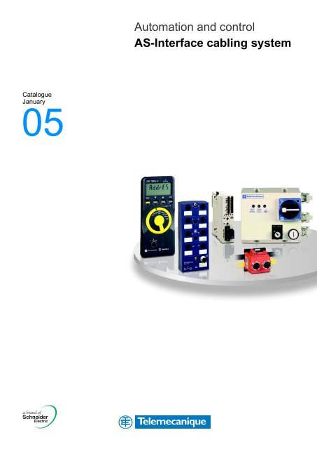
Automation and control<strong>AS</strong>-<strong>Interface</strong> <strong>cabling</strong> <strong>system</strong>CatalogueJanuary05
Art. 802731 - MKTED204073EN2004Ethernet TCP/IPTransparent FactoryArt. 67341 - MKTED203111EN2004Safety solutionsusing PreventaArt. 804961 - MKTED204121EN2005Automation and control<strong>AS</strong>-<strong>Interface</strong><strong>cabling</strong> <strong>system</strong>Human/Machine dialogueCommunicationControl and Protection,Detection,Automation,Human/Machine dialogueAn overviewof the product rangeControl and Protection,Detection,Automation,Human/Machine dialogue,CommunicationControl and signalling unitsArt. 28697 - MKTED299014ENControl and protection,Detection,Automation,Human/Machine dialogue,Communication,Supervision,Panel-building and <strong>cabling</strong>accessories2001TelemecaniqueComponents forHuman-Machine interfacesTerminals and display unitsArt. 96949 - MKTED2040401ENAutomation and controlHuman/Machine interfacesArt. 70263 - MKTED203113EN20042003Automation and control<strong>Interface</strong>s, I/O splitter boxesand power supplies2003Art. 70455 - MKTED204011ENAutomation and controlAutomation and relay functionsHuman/Machine dialogueSupervisionNot all products shown in this catalogue are available in every country.Check individual country's web site or Sales Office for product availability.See on: www.schneider-electric.com.Panel-building and <strong>cabling</strong> accessoriesAutomation
Art. 804818 - MKTED204101ENAutomation and controlIP 20 Distributed I/O AUTC201104124ENAdvantys STB2004 Modicon Momentumautomation platform20022004Art. 802621 - MKTED204071ENAutomation and controlAutomation platformModicon Quantumand Unity - ConceptProworx softwareArt. 802625 - MKTED204072ENAutomation and controlAutomation platformModicon Premiumand Unity - PL7 software2004Automation platformModicon TSX Microand PL7 software2004Art. 70984 - MKTED204012ENArt. 960015 - DIA1ED2040506EN2004Automation and controlTelemecaniqueThe essentialAutomation,CommunicationArt. 66692 - DIA7ED20310006ENArt. 61233 - DIA7ED2030902EN2004Motion controlLexiumArt. 802660 - MKTED204091EN2003Twin LineMotion controlSoft starters andvariable speed drivesArt. 27501 - MKTED201001EN2004Art. 54752 - MKTED203031EN2003Global DetectionElectronic andelectromechanical sensors2001Motor starter solutionsControl and protectioncomponentsControl and protectionDetection
General contents 0<strong>AS</strong>-<strong>Interface</strong><strong>cabling</strong> <strong>system</strong>Presentation . . . ..............................................page 41 – <strong>Interface</strong>s for generic productsSelection guide for IP 20 and IP 67 interfaces .................... page 1/2Advantys, modular interfaces IP 20, <strong>AS</strong>-<strong>Interface</strong> V2.1 ............... page 1/6Advantys, interfaces IP 67 I/O, <strong>AS</strong>-<strong>Interface</strong> V2.1 .................. page 1/232 – Dedicated componentsSelection guide: dedicated components for control. . ............. page 2/2Selection guide: dedicated components for dialogue ............. page 2/4Communication module for TeSys model U starter-controller ...... page 2/6TegoPowercommunicationmodule........................... page 2/9LA9Z<strong>AS</strong>-<strong>Interface</strong>V1,forD.O.L.starters...................... page 2/13EnclosedD.O.L.starters,ininsulatedormetalenclosures........ page 2/26Tego Dial for Human-Machine interfaces on<strong>AS</strong>-<strong>Interface</strong> <strong>cabling</strong> <strong>system</strong> ................................. page 2/45Control stations and adapter for control and signalling units. ..... page 2/47Illuminatedindicatorbanks,typeXVB......................... page 2/523 – Safety solutions on <strong>AS</strong>-<strong>Interface</strong> <strong>cabling</strong> <strong>system</strong>Selectionguide............................................. page 3/2<strong>AS</strong>-<strong>Interface</strong>"Safetyatwork"monitors......................... page 3/6<strong>AS</strong>-<strong>Interface</strong> safety interfaces ................................ page 3/104 – Installation <strong>system</strong>Selectionguide............................................. page 4/2<strong>AS</strong>-<strong>Interface</strong>cables ......................................... page 4/4Repeaters ................................................. page 4/5Connection accessories ..................................... page 4/6ExtensioncableswithM12maleconnectors .................... page 4/8M12maleconnectorsandextensioncables.................... page 4/13Phaseo regulated switch mode power supplies ................. page 4/17Powersuplymoduleandunit................................ page 4/19Insulationcontrolrelayfor<strong>AS</strong>-<strong>Interface</strong>line.................... page 4/23Master module for Twido programmable controllers . ............ page 4/25TSX SAZ master module forModiconTSXMicroprogrammablecontrollers.................. page 4/27TSX SAY master module forModiconPremiumprogrammablecontrollers................... page 4/292
Master module for Modicon Quantum programmable controllers . . . page 4/33Fipio bus/<strong>AS</strong>-<strong>Interface</strong> line gateway module ....................page4/35Modbus/Modbus plus <strong>AS</strong>-<strong>Interface</strong> line gateway modules ........page4/375 – <strong>AS</strong>-<strong>Interface</strong> toolsSelection guide for terminals ..................................page5/2<strong>AS</strong>-<strong>Interface</strong> Design installation configuration software. ...........page5/4<strong>AS</strong>-<strong>Interface</strong> V1 and V2.1 terminals .............................page5/46 – ServicesTechnical information ........................................page6/2<strong>Schneider</strong> <strong>Electric</strong> worldwide .................................page6/8Product reference index .....................................page6/153
Presentation 0<strong>AS</strong>-<strong>Interface</strong><strong>cabling</strong> <strong>system</strong> 0The <strong>AS</strong>-<strong>Interface</strong> conceptb <strong>AS</strong>-<strong>Interface</strong> is a <strong>cabling</strong> <strong>system</strong> that meets the needs of industrial automation<strong>system</strong> integration. It allows fast connection of sensors and actuators to theprogrammable controller by means of a single cable that ensures both transmissionof data and supply of power to the sensors. The <strong>AS</strong>-<strong>Interface</strong> <strong>cabling</strong> <strong>system</strong> is acost-effective alternative to parallel wiring between the PLC and thesensors/actuators.b <strong>AS</strong>-<strong>Interface</strong> is today widely used in many sectors of industry:v assembly machines,v conveyor applications,v mechanical handling,v etc.b <strong>AS</strong>-<strong>Interface</strong> is an open industry standard supported by the <strong>AS</strong>-Internationalassociation. This association, founded in 1991, counts among its members not only<strong>Schneider</strong> <strong>Electric</strong>, but also leading manufacturers of sensors, actuators,programmable controllers and connection accessories.b <strong>AS</strong>-<strong>Interface</strong> is recognized world-wide and all products conform to standardsEN 50295 and IEC 62026-2.b <strong>AS</strong>-<strong>Interface</strong> is an open <strong>system</strong> and guarantees interchangeability andinteroperability between the various products in the market. This guarantee isassured by <strong>AS</strong>-<strong>Interface</strong> certification.<strong>AS</strong>-<strong>Interface</strong> architecture<strong>AS</strong>-<strong>Interface</strong>masterEarth faultmonitor<strong>Interface</strong>s forgeneric productsDedicatedcomponentsSafetysolutionsIP 20enclosureTools<strong>AS</strong>-<strong>Interface</strong> lineAuxiliary c 24 Vpower supplyIP 65 or IP 67machine4
Presentation (continued) 0<strong>AS</strong>-<strong>Interface</strong><strong>cabling</strong> <strong>system</strong> 0The advantages of <strong>AS</strong>-<strong>Interface</strong>SimplicityThe simplicity of the <strong>AS</strong>-<strong>Interface</strong> <strong>cabling</strong> <strong>system</strong> is due to:b Use of a single cable for connecting all the sensors in an automation <strong>system</strong>.b Management of communications incorporated in the products.Reduction in costsCosts can be reduced by up to 40% as a result of:b Reduced design, installation, setting-up and implementation times.b Space saved in enclosures due to more compact products and the elimination ofintermediate enclosures, since the majority of functions can be remotely located onthe machine.b Elimination of control cable runs and reduction of the amount of cable ductingrequired.Maximum safety<strong>AS</strong>-<strong>Interface</strong> helps to improve machine reliability, operational availability and safety:b Wiring errors are no longer possible.b No risk of electrical connection failure.b High immunity to electromagnetic interference (EMC).b The safety function of the machine can be totally integrated with <strong>AS</strong>-<strong>Interface</strong>"Safety at work".<strong>AS</strong>-<strong>Interface</strong> components<strong>Interface</strong>s for generic productsThese allow any standard product (sensor, actuator, motor starter, etc.) to beconnected on the <strong>AS</strong>-<strong>Interface</strong> line. They provide great freedom in the selection ofsensors, actuators, etc. and are particularly suitable for modification or upgrading ofmachines previously wired in the traditional way.These interfaces are available for installation in enclosures (IP 20) or for directmounting on the machine (IP 65 or IP 67).Dedicated interfaces and componentsDedicated interfaces (communication module, …) allow communication with the<strong>AS</strong>-<strong>Interface</strong> line.Dedicated components incorporate an interface and can therefore be connecteddirectly on the <strong>AS</strong>-<strong>Interface</strong> line.They allow significantly faster wiring, but provide less freedom of choice thaninterfaces for generic products.The masterThis is the central component of the <strong>system</strong>. Its function is to manage the exchangeof data with interfaces and components (also called slaves) distributed in theinstallation. It can accept a maximum of 31 V1 interfaces and components (max.cycle time = 5 ms) and 62 V2.1 interfaces and components (max. cycle time =10 ms).The master may be:b Integrated in a programmable controller, for example in the form of an extension.b Connected to a field bus (for example Modbus). This is called a gateway.5
Presentation (continued) 0<strong>AS</strong>-<strong>Interface</strong><strong>cabling</strong> <strong>system</strong> 0<strong>AS</strong>-<strong>Interface</strong> components (continued)The <strong>AS</strong>-<strong>Interface</strong> power supplyProvides a PELV (Protective Extra Low Voltage) of 29.5 to 31.6 V for the interfacesand components supplied from the <strong>AS</strong>-<strong>Interface</strong> line. It ensures disconnection ofcommunication data. It is protected against overload and short-circuits. Only thistype of power supply unit can be connected to the <strong>AS</strong>-<strong>Interface</strong> line. Since thecurrent in the <strong>AS</strong>-<strong>Interface</strong> cable is limited, it is sometimes necessary to supplycertain circuits, in particular the actuators, directly or via the interface outputs, witha separate, standard c 24 V supply unit. In this case, a dual supply can be used:<strong>AS</strong>-<strong>Interface</strong> and c 24 V.The ribbon cableThe yellow cable, connected to the <strong>AS</strong>-interface power supply, performs both ofthe following functions:b Transmission of data between the master, the dedicated components, theinterfaces and the safety products (slaves).b Supply of power to the sensors.The black cable, connected to the c 24 V auxiliary power supply, provides powersupply for the actuators, but also, on certain interfaces and components, for thesensors (isolated inputs).The mechanical profile of these cables makes it impossible to reverse the polarity.The material used also allows fast and reliable connection of the variouscomponents, interfaces and accessories by means of insulation displacementconnectors (IDC). When products are removed - for example when wiring needs tobe modified - the cable resumes its original form due to its self-sealing sheath.These cables can be used both in an enclosure and on the machine. The maximumoperational current is 8 A.The ribbon cables are available in 2 types of material:b Rubber, for standard applications and maximum cable flexibility.b TPE, for applications where the cable is installed in an environment with splashingoil.Ribbon cable withmechanical profileIDC connector6
Presentation (continued) 0<strong>AS</strong>-<strong>Interface</strong><strong>cabling</strong> <strong>system</strong> 0<strong>AS</strong>-<strong>Interface</strong> components (continued)Safety solutions on <strong>AS</strong>-<strong>Interface</strong>Standard process information and information relating to safety can now betransmitted over the same cable. Capable of managing safety functions up to level 4of standard EN 60954-1, the <strong>AS</strong>-<strong>Interface</strong> "Safety at work" <strong>system</strong> meets the needsof the most common safety applications, such as:b Emergency stop monitoring with instantaneous break contacts (stop category 0).b Emergency stop monitoring with delayed break contacts (stop category 1).b Monitoring of switches with and without interlocking.b Monitoring of light curtains.Parameters for options relative to the selected safety function (such as, for example,start button monitoring) may be set for all pre-defined, certified functions.Safety is incorporated into the <strong>AS</strong>-<strong>Interface</strong> <strong>system</strong> by adding a safety monitor andsafety interfaces connected, together with other standard <strong>AS</strong>-<strong>Interface</strong> components,on the yellow cable.Safety information is only exchanged between the safety monitor and the safetyinterfaces. This is transparent for the other standard <strong>AS</strong>-<strong>Interface</strong> components.Based on this principle, <strong>AS</strong>-<strong>Interface</strong> <strong>system</strong>s that are already installed can beupdated with safety functions without having to replace the existing components(masters, input/output interfaces, power supplies, etc.). Safety circuits arediagnosed readily, and with no additional wiring, by the standard <strong>AS</strong>-<strong>Interface</strong>master communicating with the safety monitor(s) via the yellow cable.<strong>AS</strong>-<strong>Interface</strong> connection accessoriesThese are used for connecting components to the ribbon cables and for creatingtap-offs. Certain components, however, such as interfaces for generic products withIDC connectors, can be connected directly on the ribbon cable without any need foraccessories.The addressing terminalSince <strong>AS</strong>-<strong>Interface</strong> components are connected in parallel on the <strong>AS</strong>-<strong>Interface</strong> cable,it is necessary to assign an address to each of them (interfaces, motor starters,dedicated components). This function is performed by the addressing terminalwhich can be connected to the various products by means of connection cables.7
Presentation (continued) 0<strong>AS</strong>-<strong>Interface</strong><strong>cabling</strong> <strong>system</strong> 0The topology of the <strong>AS</strong>-<strong>Interface</strong> <strong>cabling</strong> <strong>system</strong> is unrestricted: point-to-point, line, tree, ring, etc...This lack of restrictions enables the most direct connections to be made between the <strong>AS</strong>-<strong>Interface</strong> <strong>system</strong> and the various sensors and actuatorsin an installation. The maximum length of the <strong>AS</strong>-<strong>Interface</strong> line is 100 m (including main runs and tap-off runs). Runs of up to 300 m are possibleusing repeaters (signal regenerators).Point-to-pointLineTreeRing8
Presentation (continued) 0<strong>AS</strong>-<strong>Interface</strong><strong>cabling</strong> <strong>system</strong> 0<strong>AS</strong>-<strong>Interface</strong> <strong>system</strong> versionsThe original version of the <strong>AS</strong>-<strong>Interface</strong> <strong>system</strong> (V1) has been followed byversion V2.1, which incorporates the following enhancements:b Possibility of connecting a maximum of 62 slaves, compared with 31 previously,by means of a 2-bank addressing <strong>system</strong> (called extended or A/B addressing).b Possibility of transmitting a "peripheral fault" message to the <strong>AS</strong>-<strong>Interface</strong> masterwithout totally inhibiting the slave (continuity of service). This means thatcommunication faults can be separated from faults associated with the productperipherals.b Management of analogue slaves.Important: products that conform to the V2.1 specification do not necessarilyinclude all these enhancements.Extended or A/B addressing<strong>AS</strong>I20MT4IE(A/B addressing)address 2A<strong>AS</strong>ILUFC5(std addressing)address 3<strong>AS</strong>ISSLB4(std addressing)address 4<strong>AS</strong>I20MT211OTE(A/B addressing)address 5A<strong>AS</strong>I20MT413OSE(A/B addressing)address 7A1 2 3 4 5 6 7 8 9 29 30 31Bank ABank BXALS2001(std addressing)address 1<strong>AS</strong>I 67FFP22E(A/B addressing)address 2B<strong>AS</strong>I 67FFP40E(A/B addressing)address 5B<strong>AS</strong>ISAFEMON1(std addressing)address 6<strong>AS</strong>I20MT414OS(std addressing)address 8<strong>AS</strong>-<strong>Interface</strong> masters developed according to the V2.1 specification have2 addressing banks, A and B.b V2.1 slaves with extended addressing (A/B) connected to this type of master onlyoccupy one of the 2 banks (A or B), allowing up to 62 slaves to be addressed.b V2.1 slaves with standard addressing or V1 slaves can only be addressed in bankA and bank B of the same address is no longer available.It is quite possible to mix V1, V2.1 standard addressing and V2.1 extendedaddressing slaves, but in this case the total number of slaves will be less than 62.<strong>Schneider</strong> <strong>Electric</strong> PLC programming software packages automatically generate themaximum number of slaves possible, according to the type of addressing of theproducts (standard or extended).The scan time for slaves with extended addressing will be twice that of slaves withstandard addressing.Configurations with 4 inputs/4 outputs and with 4 outputs cannot be achieved withextended addressing; they are replaced by configurations with 4 inputs/3 outputsand with 3 outputs.9
NL24 V<strong>AS</strong>-i : 2,4 APresentation (continued) 0<strong>AS</strong>-<strong>Interface</strong><strong>cabling</strong> <strong>system</strong> 0<strong>AS</strong>-<strong>Interface</strong> versions (continued)Peripheral faultThis new function allows any problem external to the <strong>AS</strong>-<strong>Interface</strong> <strong>cabling</strong> <strong>system</strong> tobe signalled to the PLC and, in particular:b A short-circuit in the sensor supply.b Absence of auxiliary voltage.b Short-circuit or overload on the outputs.On V1 slaves, faults of this type result in total inhibition of the slave, which is nolonger "seen" by the PLC.AnalogueTwo new profiles make it possible to use slaves with analogue inputs. The types ofinput available are:b Voltage 0-10 V.b Current 0-20 mA or 4-20 mA.Compatibility between master and slave versionsV1 slavesV2.1 slaves withstandard addressingV1 masters Compatible Compatible but peripheralfaults are not signalled tothe masterV2.1 slaves withstandard addressingNot compatibleV2.1 analogue slavesNot compatibleV2.1 masters Compatible Compatible Compatible CompatibleExample of machine cabled with the <strong>AS</strong>-<strong>Interface</strong> <strong>system</strong>1 2345123456 6 61 Power supplies <strong>AS</strong>I ABLppppp2 Master TWD NOI 10M33 Safety monitors <strong>AS</strong>I SAFEMONp4 IP 20 interfaces for generic products <strong>AS</strong>I 20Mppp5 <strong>Interface</strong>s for TeSys model U starters: <strong>AS</strong>I LUFC51 IP 67 interfaces for generic products <strong>AS</strong>I 67FpPppp2 Motor starters LF1/LF2/LF7/LF83 <strong>Interface</strong> for Emergency stop <strong>AS</strong>I SSLB44 Control stations XAL S200p5 Illuminated indicator banks XVB C21p6 Tap-offs for ribbon cable: XZ CGpppp, <strong>AS</strong>I DCPpppp10
Presentation (continued) 0<strong>AS</strong>-<strong>Interface</strong><strong>cabling</strong> <strong>system</strong> 0Setting-upProducts connected to the As-<strong>Interface</strong> cableOnly the “<strong>AS</strong>-<strong>Interface</strong> +” and “<strong>AS</strong>-<strong>Interface</strong> -” terminals of a product may beconnected to the <strong>AS</strong>-<strong>Interface</strong> cable.EarthingThe earth terminals (Shd or Gnd) on products must be connected to the machineearth and to the enclosure earth, and these points must be themselves connectedto earth:b <strong>AS</strong>-<strong>Interface</strong> supply.b Auxiliary supply.b Earth fault monitor.b Safety monitor.b <strong>AS</strong>-<strong>Interface</strong> master.b Programmable controller rack.In addition to double insulation of the <strong>AS</strong>-<strong>Interface</strong> supply, this condition ensures:b Safety of personnel on an <strong>AS</strong>-<strong>Interface</strong> line.b Good resistance to electromagnetic interference (EMC).Connection of power suppliesb If a switch has to break the <strong>AS</strong>-<strong>Interface</strong> supply, then it must be located upstreamof the <strong>AS</strong>-<strong>Interface</strong> supply: the switch must not be installed on the <strong>AS</strong>-<strong>Interface</strong>line.b If a switch has to break a programmable controller’s supplies, then this switchmust be common to the PLC's <strong>AS</strong>-<strong>Interface</strong> supply and to its auxiliary supply (24 Vor 220 V). This makes it possible to ensure that both supplies are switched on andoffatthesametime.b It is recommended that <strong>AS</strong>-<strong>Interface</strong> supplies be installed close to theprogrammable controllers.Use of an earth fault monitorIn order to conform to machine standard EN 60204-1 (in particular paragraph9.4.3.1 concerning earth faults), the <strong>AS</strong>-<strong>Interface</strong> <strong>system</strong> must include an earth faultmonitor. The earth fault monitor may be:b Either separate from the power supply (example: RMOP<strong>AS</strong>101),b Or built into the power supplies (example: <strong>AS</strong>I ABLD300p).Cable lengths<strong>AS</strong>-<strong>Interface</strong> cablesWe recommend use of the yellow ribbon cable (see page 8). The maximum lengthof an <strong>AS</strong>-<strong>Interface</strong> run is 100 m, which can be extended to 200 m by using onerepeater (see page 10) or to 300 m with 2 repeaters. It is not possible to exceed adistance of 300 m between the master and the most distant slave. By placing themaster in the middle of the network, runs of up to 500 m are possible.MAAA A AA AMS S S S100 m 100 mM = Master moduleA = SupplyS = <strong>Interface</strong> or componentS S S SS S S S S S S S100 m 100 m 50 m 50 m 100 m 100 m11
Presentation (continued) 0<strong>AS</strong>-<strong>Interface</strong><strong>cabling</strong> <strong>system</strong> 0Setting-up (continued)Cable lengths (continued)Calculating cable lengthsThe total length of cable and wires connected to the <strong>AS</strong>-<strong>Interface</strong> + terminals and<strong>AS</strong>-<strong>Interface</strong> - terminals of the master must be carefully counted, both inside andoutside the enclosure, including the lengths of tap-offs in cases where <strong>AS</strong>-<strong>Interface</strong>components are not installed directly on the yellow cable using the IDC <strong>system</strong>.Lengths of tap-off cables must be counted twice. We therefore recommend usingshort tap-off runs and, wherever possible, using products installed directly on theyellow cable via IDC connectors (example: IP 67 interfaces, references<strong>AS</strong>I 67FFPppp).2 m2 m2 m0,3 mTotal length of ribbon cableTotal length of round wireTotal length of tap-offsLength of network=40m=Lc=2m=Lf=4.3m=Ld= Lc + Lf + 2 x Ld = 50.60 mCables between sensors/actuators and interface inputsSensors/actuators must be supplied with power directly at the <strong>AS</strong>-<strong>Interface</strong> interfaceterminals or connectors. The sensor supply must not be connected to any potential.Maximum lengths are:b Between safety sensors and safety interfaces: 3 m (2 m recommended).b Between standard sensors/actuators and interfaces: 10 m.12
Presentation (continued) 0<strong>AS</strong>-<strong>Interface</strong><strong>cabling</strong> <strong>system</strong> 0Setting-up (continued)Cable routingb Do not route the <strong>AS</strong>-<strong>Interface</strong> cable with other cables in the same strand. Inexceptional circumstances, it is permissible to run cables carrying low power signals(for example: wires connected to start/stop buttons) close to the <strong>AS</strong>-<strong>Interface</strong> + and<strong>AS</strong>-<strong>Interface</strong> - cables.b Do not route the <strong>AS</strong>-<strong>Interface</strong> cable close to sources of interference (variatorcables, etc...) including inside the enclosure.b To ensure symmetry, the <strong>AS</strong>-<strong>Interface</strong> cable must be laid flat in relation to thesupport on which it is fixed, especially if the support is in metal.v the end of the <strong>AS</strong>-<strong>Interface</strong> cable must be protected (never leave the end of thecable open), for example by terminating the line with an IP 67 interface,v in an enclosure, when standard wire is used for <strong>cabling</strong> <strong>AS</strong>-<strong>Interface</strong> + and<strong>AS</strong>-<strong>Interface</strong> - lines, these wires must be of the same length and must be laid inparallel. They must be spaced no more than 10 mm apart.Limiting the interference emittedby certain productsIn order to limit the electromagnetic disturbance emitted by products, a number ofrecommendations must be taken into account:b Fit frequency variators with suitable filters.b Use screened cables between the variator and the motor.b Fit inductive loads (coils of contactors, relays, brakes, solenoid valves etc.) withflywheel diodes, varistors or RC circuits.When it is not possible to completely eliminate emitted interference, is it essential toensure that the following distances are maintained.b In the case of an <strong>AS</strong>-<strong>Interface</strong> installation including safety products,the <strong>AS</strong>-<strong>Interface</strong> cable or the safety input cables must be located at a distancegreater than:v 50 cm from products which have a control circuit with inductive load (relays,contactors, coils, reversing contactors, etc...).v 100 cm from products such as welding machines, power circuits in general,electronic speed regulators, switch mode power supplies.b In the case of an <strong>AS</strong>-<strong>Interface</strong> that does not include safety products, the<strong>AS</strong>-<strong>Interface</strong> cable or standard sensor/actuator cables must be located as adistance greater than:v 10 cm from products which have a control circuit with inductive load (relays,contactors, coils, reversing contactors, etc...).v 50 cm from products such as welding machines, power circuits in general,electronic speed regulators, switch mode power supplies.In all cases, we recommend that the practical installation guidelines in the <strong>Schneider</strong><strong>Electric</strong> EMC manual be followed (please consult your Regional Sales Office).13
1/0
Contents 01-Advantys,interfaces for generic productsSelection guide for IP 20 and IP 67 interfaces. . . ................page1/2b Advantys, modular interfaces IP 20, <strong>AS</strong>-<strong>Interface</strong> V2.1v For analogue inputs. ...................................... page 1/6v For discrete inputs/outputs ................................ page 1/111b Advantys, interfaces IP 67 I/O, <strong>AS</strong>-<strong>Interface</strong> V2.1v Direct connection interfaces ............................... page 1/23v <strong>Interface</strong>s with remote M12 connector. ....................... page 1/25b Connection of sensors and actuators to Advantys <strong>AS</strong>I 67F interfaces . page 1/32b Jumper cables for connection of conventional sensors. ............ page 1/36b Connection of sensors and actuators on the <strong>AS</strong>-<strong>Interface</strong> linev Compatibility table for connection ofTelemecanique brand sensors ............................ page 1/371/1
Selection guide 1<strong>AS</strong>-<strong>Interface</strong><strong>cabling</strong> <strong>system</strong> 1Advantys, interfaces for generic productsIP 20 and IP 671Description Analogue modular interfaces Discrete modular interfacesDegree of protection IP 20Functions Connection of 1 to 2 analogue sensors Connection of 1 to 8 discrete sensors/actuatorsConnection of sensors/actuatorsBy removable screw clamp connectors (optional spring terminal connectors)Supply for the inputs and sensors Via the <strong>AS</strong>-<strong>Interface</strong> line Via the <strong>AS</strong>-<strong>Interface</strong> line or via c 24 V externalpower supplySupply for the outputs – Via c 24 V external power supplyConnection to the <strong>AS</strong>-<strong>Interface</strong> and auxiliary supplyBy removable screw clamp connectors (optional IDC connectors)<strong>AS</strong>-<strong>Interface</strong> version V2.1Extended addressing No YesI/O configurations 2 inputs: 0/4…20 mA or 2 inputs 0…10 V 2 inputs/1 output, 4 inputs, 4 inputs/4 outputs,4 inputs/3 outputsOutput type – Relay or triac 2 A,Transistor 0.5 AType <strong>AS</strong>I 20MApp <strong>AS</strong>I 20MTppPages 1/6 1/111/2
11Telefast compact discrete interfaces Discrete interfaces, direct connection Discrete interfaces, remote connection1IP 20 IP 67Connection of 1 to 8 discrete sensors/actuatorsConnection of 1 to 8 discrete sensors/actuatorsBy removable screw connectorsBy M12 connectorVia the <strong>AS</strong>-<strong>Interface</strong> line or via c 24 V externalpower supplyVia the <strong>AS</strong>-<strong>Interface</strong> lineVia c 24 V external power supplyBy removable screw connectors Directly to the ribbon cable by IDC connectors By M12 connectorV1 V2.1 and V1 compatible V2.1NoYes4 inputs, 4 inputs/4 outputs, 4 outputs 4 inputs, 2 inputs/2 outputs, 4 inputs/4 outputs, 3 outputs, 4 outputs, 4 inputs/3 outputsRelay 2A,Transistor 0.5 ATransistor 2 AABE 8pp <strong>AS</strong>I 67FFPppp <strong>AS</strong>I 67FMPpppPlease consult your Regional Sales Office (1) 1/23 and 1/24 1/25(1) Products used only for maintenance.1/3
Presentation 1<strong>AS</strong>-<strong>Interface</strong><strong>cabling</strong> <strong>system</strong> 1Advantys, interfaces for generic productsIP 20, <strong>AS</strong>-<strong>Interface</strong> V2.1Modular, for analogue inputs11 2 3Presentation<strong>AS</strong>I 20MA modular interfaces enable analogue output sensors (proximity, pressure,temperature sensors...) to be connected to the <strong>AS</strong>-<strong>Interface</strong> <strong>cabling</strong> <strong>system</strong>.Due to their particularly compact size, they are suitable for fitting in small-sizeenclosures as well as in larger, floor-standing enclosures.Inputs are of the current type (0-10 mA or 4-20 mA, depending on connection) orvoltage type (0-10 V), and supply to the sensors is from the <strong>AS</strong>-<strong>Interface</strong> line.All connectors are of the removable type and are supplied with screw terminal blockas standard. Quick connect terminal blocks are available as an accessory. A "Jack"connector on the front panel allows addressing of the product independently, or wheninstalled.Composition<strong>AS</strong>-<strong>Interface</strong> connection:1 <strong>AS</strong>I 20MACC4 screw terminal block, fitted as standard.2 <strong>AS</strong>I 20MACC1 insulation displacement connector for chaining, to be orderedseparately.3 APE1 PAD21 self-stripping connector, to be ordered separately.Sensor connection:4 <strong>AS</strong>I 20MACC2 screw terminal block, fitted as standard.5 <strong>AS</strong>I 20MACC3 spring terminal connector, to be ordered separately.54ChainingThe <strong>AS</strong>-<strong>Interface</strong> line can be chainedusing an <strong>AS</strong>I 20MACC1 insulationdisplacement connector, to be orderedseparately.109481-28-M152634Description1 Removable screw terminal block for connection of the <strong>AS</strong>-<strong>Interface</strong> line. Thisterminal block can be replaced by an APE 1PAD21 self-stripping block forconnecting a single interface, or by an <strong>AS</strong>I 20MACC1 quick connect block forchaining several <strong>AS</strong>I 20MA interfaces.2 Removable labels for marking the interface and the address, fitted as standard.3 Removable screw terminal block for connection of the inputs and of the powersupply for the sensors. This terminal block can be replaced by an <strong>AS</strong>I 20MACC3quick connect terminal block.4 Not used.5 Diagnostic LED.6 “Jack” connector for connection of an <strong>AS</strong>I TERACC2 cable (see page 5/5) foraddressing and diagnostic terminal type <strong>AS</strong>I TERV2 or XZ MC11.7 Fitting for clipping onto 35 mm symmetrical DIN rail and screw fixing onto panel.71/4
Characteristics 1<strong>AS</strong>-<strong>Interface</strong><strong>cabling</strong> <strong>system</strong> 1Advantys, interfaces for generic productsIP 20, <strong>AS</strong>-<strong>Interface</strong> V2.1Modular, for analogue inputsEnvironmentProduct certificationsUL, CSA, GL (pending)Operating temperature °C -20…+60Storage temperature °C -40…+85Degree of protection Conforming to IEC/EN 60529 IP 20Shock resistance Conforming to IEC/EN 60068-2-27 15 gn (for 11 ms)Vibration resistance Hz 2…13.2 amplitude ± 1 mm, 13.2…100: 1 gnResistance to electrostatic Conforming to IEC/EN 61000-4-2 Level 3dischargeResistance to radiated fields Conforming to IEC/EN 61000-4-3 V/m 10Resistance to transients Conforming to IEC/EN 61000-4-4 kV 2Overvoltage category Conforming to IEC/EN 60664-1 IIDegree of pollution Conforming to IEC/EN 60664-1 21<strong>AS</strong>-<strong>Interface</strong> characteristics<strong>AS</strong>-<strong>Interface</strong> version V2.1<strong>AS</strong>-<strong>Interface</strong> profile (I/O code, ID code, ID1, ID2) (1)S7.3.F.DMaximum number of addresses 31<strong>AS</strong>-<strong>Interface</strong> supply c V 26.5…31.6Consumption on the<strong>AS</strong>-<strong>Interface</strong> lineNo-load mA 60Maximum mA 250Diagnostic signalling <strong>AS</strong>-<strong>Interface</strong> power ON Green LEDFault (2)RedLEDandfaultbitParameter bit P0 Not usedP10: input 1 On, input 2 Off,1: input 1 On, input 2 OnP21: fault bit OnP3Not usedMountingOn 35 mm 5 rail (horizontal only) or screw fixing using 2 x Ø 3 screwsHousing materialPolycarbonate (UL94VO)Connection <strong>AS</strong>-<strong>Interface</strong> Removable terminal block<strong>AS</strong>I 20MACC4: 0.2 to 2.5 mm 2 ; <strong>AS</strong>I 20MACC1: 0.5 to 0.75 mm 2 ;APE 1PAD2: 0.5 to 0.75 mm 2SensorsRemovable terminal block<strong>AS</strong>I 20MACC2: max 1.5 mm 2 ;<strong>AS</strong>I20MACC3:0.14to1.5mm 2Analogue input characteristics (sensor side)<strong>Interface</strong> type <strong>AS</strong>I 20MA2VU <strong>AS</strong>I 20MA2VIInputs Voltage c V 0…10 –Current c mA – 0…20 or 4…20Sensor input typeAnalogueMax. permissible value without destruction (3) c V 14 –c mA – 24Supply to sensors V Viathe<strong>AS</strong>-<strong>Interface</strong>lineonlyInput impedance Ω 20 000 250Range of values decimal 0…10 000 0…20 000 or 4000…20 000Resolution bits 12Refresh time ms 10.5 V (VU), current < 1 mA or > 21 mA (VI).(3) The inputs are not protected above these values.1/5
References 1<strong>AS</strong>-<strong>Interface</strong><strong>cabling</strong> <strong>system</strong> 1Advantys, interfaces for generic productsIP 20, <strong>AS</strong>-<strong>Interface</strong> V2.1Modular, for analogue inputs1109481ReferencesModular interfaces supplied with removable screw terminal blocksInputs (1) Reference WeightNumberTypekg2 c 0…10 V <strong>AS</strong>I 20MA2VU 0.090<strong>AS</strong>I 20MA2Vpc 0…20 mAc 4…20 m<strong>AS</strong>pare partsDescription For use with Terminalblock typeSold inlots ofConnectors <strong>AS</strong>-<strong>Interface</strong> Screw 5yellow+ 5 black<strong>AS</strong>I 20MA2VI 0.090Unit reference Weightkg<strong>AS</strong>I 20MACC4 0.010InsulationDisplacementConnectorSelf-strippingconnector5yellow+ 5 black<strong>AS</strong>I 20MACC1 0.01016 grey APE 1PAD21 0.003Inputs (2) Screw 10 <strong>AS</strong>I 20MACC2 0.020Spring 10 <strong>AS</strong>I 20MACC3 0.020Labels – – 22 <strong>AS</strong>I 20MACC5 –(1) The inputs and sensor electronics are supplied from the <strong>AS</strong>-<strong>Interface</strong> line.(2) Connectors supplied with locating facility not activated; locating facility to be activated bycutting off a lug.1/6
Dimensions,connections 1<strong>AS</strong>-<strong>Interface</strong> <strong>cabling</strong> <strong>system</strong> 1Advantys, interfaces for generic productsIP 20, <strong>AS</strong>-<strong>Interface</strong> V2.1Modular, for analogue inputsDimensionsConnections<strong>AS</strong>I 20MA2Vp <strong>AS</strong>I 20MA2Vp <strong>AS</strong>I 20MA2VU<strong>AS</strong>-<strong>Interface</strong>+1S +I1+8287<strong>AS</strong>-<strong>Interface</strong><strong>AS</strong>-<strong>Interface</strong> +R = 20 kΩS –S +I20…10 V+1,577 2512S +I1S –S +I2S –R = 20 kΩS –0…10 Vd The sensors do not have to be supplied froman external source.The inputs are not protected against overvoltage.<strong>AS</strong>I 20MA2VI1 red “FAULT” LED2 green “<strong>AS</strong>I PWR” LED<strong>AS</strong>-<strong>Interface</strong>+S ++Connection examplefor a 3-wire sensorI10…10 m<strong>AS</strong> –S ++I24…20 m<strong>AS</strong> –Connection examplefor a 2-wire sensorLED signallingNormal operationd The sensors do not have to be supplied froman external source.The inputs are not protected against overcurrent.LED <strong>AS</strong>I PWR FAULT<strong>AS</strong>-<strong>Interface</strong> exchange fault<strong>AS</strong>I 20MA2VU input overload: U > 10.5 V<strong>AS</strong>I 20MA2VI input overload or underload:I21mA(1) Flashing.(1)1/7
Presentation 1<strong>AS</strong>-<strong>Interface</strong><strong>cabling</strong> <strong>system</strong> 1Advantys, interfaces for generic productsIP 20, <strong>AS</strong>-<strong>Interface</strong> V2.1Modular, for discrete inputs/outputs11 2 3Presentation<strong>AS</strong>I 20MT modular interfaces enable traditional discrete sensors and actuators(sensors, motor starters, pushbuttons, pilot lights...) to be connected to the<strong>AS</strong>-<strong>Interface</strong> <strong>cabling</strong> <strong>system</strong>.Due to their particularly compact size, they are suitable for fitting in small-sizeenclosures (pushbutton and pilot light interfacing) as well as in larger, floor-standingenclosures.Conforming to the <strong>AS</strong>-<strong>Interface</strong> V2.1 specification, they offer diagnostic functionsand are available, depending on the model, with standard addressing (up to31 Slaves per Master) or with extended A/B addressing (up to 62 Slaves per Master).The inputs are compatible with 2 and 3-wire sensors, supply to the the sensors beingprovided, depending on the model, via the <strong>AS</strong>-<strong>Interface</strong> line or by an external c 24 Vsource (isolated inputs).The outputs, supplied by an external source, are of the relay or 2 A triac or 0.5 Atransistor type.All connectors are of the removable type and are supplied with screw terminal blockas standard. Quick connect terminal blocks are available as an accessory. A "Jack"connector on the front panel allows allows addressing of the product independently,or when installed.Composition<strong>AS</strong>-<strong>Interface</strong> and auxiliary supply connection:1 <strong>AS</strong>I 20MACC4 screw terminal blocks, fitted as standard.2 <strong>AS</strong>I 20MACC1 insulation displacement connectors for chaining, to be orderedseparately.3 APE 1PAD21 self-stripping connectors, to be ordered separately.Sensor/actuator connection:4 <strong>AS</strong>I 20MACC2 screw terminal blocks, fitted as standard.5 <strong>AS</strong>I 20MACC3 spring terminal connectors, to be ordered separately.5ChainingThe <strong>AS</strong>-<strong>Interface</strong> line and the auxiliarysupply can be chained using<strong>AS</strong>I 20MACC1 insulation displacementconnectors, to be ordered separately.4109482-28-M10128396475Description1 Removable screw terminal block for connection of a c 24 V PELV (ProtectiveExtra Low Voltage) auxiliary power supply, for supply to the transistor outputs andthe isolated inputs. This terminal block can be replaced by an APE 1PAD21 selfstrippingblock or an <strong>AS</strong>I 20MACC1 quick connect block for chaining several<strong>AS</strong>I 20MT interfaces.2 Removable screw terminal block for connection of the <strong>AS</strong>-<strong>Interface</strong> line. Thisterminal block can be replaced by an APE 1PAD21 self-stripping block or an<strong>AS</strong>I 20MACC1 quick connect block for chaining several <strong>AS</strong>I 20MT interfaces.3 Removable labels for marking the interface and the address, fitted as standard.4 Removable screw terminal block for connection of the inputs and of the powersupply for the sensors. This terminal block can be replaced by an <strong>AS</strong>I M20ACC3quick connect terminal block. This terminal block is fitted with a locating facility toprevent inversion of the 2 terminal blocks on the front panel.5 <strong>AS</strong>I 20MACC2 removable screw terminal block for connection of the outputs andof the power supply for the relay and triac outputs. This terminal block can bereplaced by an <strong>AS</strong>I 20MACC3 quick connect terminal block.6 Input status LED.7 Output status LED.8 Diagnostic LED.9 “Jack” connector for connection of an <strong>AS</strong>I TERACC2 cable (see page 5/5) foraddressing and diagnostic terminal type <strong>AS</strong>I TERV2 or XZ MC11.10Device for clipping onto 35 mm symmetrical DIN rail and screw fixing onto panel.1/8
Characteristics 1<strong>AS</strong>-<strong>Interface</strong><strong>cabling</strong> <strong>system</strong> 1Advantys, interfaces for generic productsIP 20, <strong>AS</strong>-<strong>Interface</strong> V2.1Modular, for discrete inputs/outputsEnvironmentProduct certificationsUL, CSA, GL (pending)Operating temperature °C -20…+60Storage temperature °C -40…+85Degree of protection Conforming to IEC/EN 60529 IP 20Shock resistance Conforming to IEC/EN 60068-2-27 15 gn (for 11 ms)Vibration resistance Hz 2…13.2 amplitude ± 1 mm, 13.2…100: 1 gnResistance toConforming to IEC/EN 61000-4-2 kV 6electrostatic dischargeResistance to radiated fields Conforming to IEC/EN 61000-4-3 V/m 10Resistance to transients Conforming to IEC/EN 61000-4-4 kV 2Dielectric test voltage Conforming to IEC/EN 60364-4-41 V 500 (transistor outputs), 3750 (relay and triac outputs)between <strong>AS</strong>-<strong>Interface</strong> lineand the outputsOvervoltage category Conforming to IEC/EN 60664-1 IIDegree of pollution Conforming to IEC/EN 60664-1 21<strong>AS</strong>-<strong>Interface</strong> characteristics<strong>AS</strong>-<strong>Interface</strong> version V2.1<strong>AS</strong>-<strong>Interface</strong> supply c V 26.5…31.6Diagnostic signalling <strong>AS</strong>-<strong>Interface</strong> power ON Green LEDAuxiliary supply ONGreen LEDInput/output statusYellow LEDFault (1)Red LEDN° of data bits/n° of inputs or outputs D0 Input 1 or output 1D1 Input 2 or output 2D2 Input 3 or output 3D3 Input 4 or output 4Value of input or output status data bit D0 to D3 0 = input or output OFF1 = input or output ONOutput fallback if watchdog tripped Output state 0Parameter bitNot usedMountingOn 35 mm 5 rail (horizontal only) or screw fixing using 2 x Ø 3 screwsHousing materialPolycarbonate (UL94VO)Connection <strong>AS</strong>-<strong>Interface</strong> Removable terminal block<strong>AS</strong>I 20MACC4: 0.2 to 2.5 mm 2 ; <strong>AS</strong>I 20MACC1: 0.5 to 0.75 mm 2 ;APE 1PAD21: 0.5 to 0.75 mm 2SensorsRemovable terminal block<strong>AS</strong>I 20MACC2: max 1.5 mm 2 ;<strong>AS</strong>I20MACC3:0.14to1.5mm 2(1) Fault LED:off = no fault,on steady = no data exchange on <strong>AS</strong>-<strong>Interface</strong>,flashing = peripheral fault.1/9
Characteristics (continued) 1<strong>AS</strong>-<strong>Interface</strong><strong>cabling</strong> <strong>system</strong> 1Advantys, interfaces for generic productsIP 20, <strong>AS</strong>-<strong>Interface</strong> V2.1Modular, for discrete inputs/outputs1<strong>AS</strong>-<strong>Interface</strong> characteristics specific to I/O with standard addressing<strong>Interface</strong> type <strong>AS</strong>I 20MT4I4OR 20MT4I4OS 20MT4I4OSAMaximum number of addresses for one master 31Number of inputs 4 4 4isolated(1)Number of outputs 4x2Arelay 4 x 0.5 A transistorSupply to the sensors (inputs) Via the <strong>AS</strong>-<strong>Interface</strong> line max: 200 mA Via external PELV (2) powersupply (AUX) max: 200 m<strong>AS</strong>upply to the actuators (outputs)External a 250 V max, Via external PELV (2) power supply (AUX)c 150 V maxProfile (I/O code, ID code, ID1, ID2) (3)S7.0.F.E<strong>AS</strong>-<strong>Interface</strong> certifications N° 52101 N° 52301 N° 52401Consumption onthe <strong>AS</strong>-<strong>Interface</strong> lineNo-load mA 15 15 15Maximum (4) mA 110 50 20<strong>AS</strong>-<strong>Interface</strong> characteristics specific to I/O with extended A/B addressing<strong>Interface</strong> type <strong>AS</strong>I 20MT4IE 20MT2I1OTE 20MT4I3ORE 20MT4I3OSE 20MT4I3OSAEMaximum number of addresses for one master 62Number of inputs 4 2 4 4 4isolated(1)Number of outputs – 1x2Atriac 3x2Arelay 3x0.5AtransistorSupply to the sensors (inputs)Via the <strong>AS</strong>-<strong>Interface</strong> linemax: 170 m<strong>AS</strong>upply to the actuators (outputs) – Externala 24…250 VVia the<strong>AS</strong>-<strong>Interface</strong>linemax: 170 mAExternalmax: a 250 VVia the<strong>AS</strong>-<strong>Interface</strong>linemax: 150 mAVia externalPELV (2) powersupply (AUX)max: 200 mAVia external PELV (2) powersupply (AUX)Profile (I/O code, ID code, ID1, ID2) (3) S0.A.7.0 S3.A.7.0 S7.A.7.0<strong>AS</strong>-<strong>Interface</strong> certification n° 52501 53801 52201 52302 52401Consumption onthe <strong>AS</strong>-<strong>Interface</strong> lineNo-load mA 15 15 15 15 15Maximum (4) mA 50 40 90 50 20Input characteristics (sensor side)<strong>Interface</strong> type <strong>AS</strong>I 20MT4IE 20MT4I4OR20MT4I3ORESensor typePNP 2 or 3-wireState 1 guaranteedU>11VandI>6m<strong>AS</strong>tate 0 guaranteedU
References,dimensions 1<strong>AS</strong>-<strong>Interface</strong> <strong>cabling</strong> <strong>system</strong> 1Advantys, interfaces for generic productsIP 20, <strong>AS</strong>-<strong>Interface</strong> V2.1Modular, for discrete inputs/outputsReferences109483109481Modular interfaces supplied with removable screw terminal blocksType ofaddressingNumberof inputs (1)Number,type of outputsReferenceWeightkg1Standard 4 4 x z 250 V/2 A relay <strong>AS</strong>I 20MT4I4OR 0.0904xc 24 V/0.5 A transistor <strong>AS</strong>I 20MT4I4OS 0.0904 isolated 4 x c 24 V/0.5 A transistor <strong>AS</strong>I 20MT4I4OSA 0.090Extended A/B 4 – <strong>AS</strong>I 20MT4IE 0.0902 1 x a 250 V/2 A triac <strong>AS</strong>I 20MT2I1OTE 0.090<strong>AS</strong>I 20MT4I4OR<strong>AS</strong>I 20MT4IE4 3 x z 250 V/2 A relay <strong>AS</strong>I 20MT4I3ORE 0.0903xc 24 V/0.5 A transistor <strong>AS</strong>I 20MT4I3OSE 0.0904 isolated 3 x c 24 V/0.5 A transistor <strong>AS</strong>I 20MT4I3OSAE 0.090<strong>AS</strong>I 20MT4I3OSESpare partsDescription For use with Terminalblock typeConnectors <strong>AS</strong>-<strong>Interface</strong> Screwand auxiliaryInsulationDisplacementConnectorSelf-strippingconnectorInputs/outputs(2)Sold inlots of5yellow+5black5yellow+5blackUnitreferenceWeightkg<strong>AS</strong>I 20MACC4 0.010<strong>AS</strong>I 20MACC1 0.01016 grey APE 1PAD21 0.240Screw 10 <strong>AS</strong>I 20MACC2 0.020Spring 10 <strong>AS</strong>I 20MACC3 0.020Legends – – 22 <strong>AS</strong>I 20MACC5 –Dimensions<strong>AS</strong>I 20MTppp(1) Unless marked "isolated", the inputs and sensor electronics are supplied from the<strong>AS</strong>-<strong>Interface</strong> line.(2) Connectors supplied with locating facility not activated; locating facility to be activated bycutting off a lug.LED signallingLED <strong>AS</strong>I PWR AUX PWR FAULTNormal operation123Outputshort-circuited (1)82874No auxiliary supply(1)<strong>AS</strong>-<strong>Interface</strong>exchange fault1,5LEDInputs/outputs77 25ON1 red “FAULT” LED2 green “<strong>AS</strong>I PWR” LED3 green “AUX PWR” LED4 yellow LEDs: inputs/outputsOFF(1) Flashing.1/11
Schemes,connections 1<strong>AS</strong>-<strong>Interface</strong> <strong>cabling</strong> <strong>system</strong> 1Advantys, interfaces for generic productsIP 20, <strong>AS</strong>-<strong>Interface</strong> V2.1Modular, for discrete inputs/outputs1<strong>AS</strong>I 20MT4I4OR<strong>AS</strong>-<strong>Interface</strong>+I1<strong>AS</strong>I 20MT4I4OSAUX <strong>AS</strong>-<strong>Interface</strong>+ +I1I2AUX –AUX + (auxiliary)I2<strong>AS</strong>-<strong>Interface</strong><strong>AS</strong>-<strong>Interface</strong> +I3<strong>AS</strong>-<strong>Interface</strong><strong>AS</strong>-<strong>Interface</strong> +I3I4Out+I4Out+I1I2I3I4S +S –O1O2O3O4CommonS +S –O1O2O3O4CC4Amax4Amax– F< a 250 V< c 150 VI1I2I3I4S +S –O1O2O3O4AUX –AUX –AUX –S +S –O1O2O3O4AUX –2Amax<strong>AS</strong>I 20MT4I4OSA<strong>AS</strong>I 20MT4IEAUX <strong>AS</strong>-<strong>Interface</strong>+ +I1<strong>AS</strong>-<strong>Interface</strong>+I1AUX –AUX + (auxiliary)<strong>AS</strong>-<strong>Interface</strong><strong>AS</strong>-<strong>Interface</strong> +I2<strong>AS</strong>-<strong>Interface</strong><strong>AS</strong>-<strong>Interface</strong> +I2I3I3I4Out+I4Out+I1I2I3I4S +S–O1O2O3O4AUX –AUX –I
Schemes,connections (continued) 1<strong>AS</strong>-<strong>Interface</strong> <strong>cabling</strong> <strong>system</strong> 1Advantys, interfaces for generic productsIP 20, <strong>AS</strong>-<strong>Interface</strong> V2.1Modular, for discrete inputs/outputs<strong>AS</strong>I 20MT2I1OTE<strong>AS</strong>-<strong>Interface</strong>+I1<strong>AS</strong>I 20MT4I3ORE<strong>AS</strong>-<strong>Interface</strong>+I11+I2OutI2<strong>AS</strong>-<strong>Interface</strong><strong>AS</strong>-<strong>Interface</strong> +n.c.n.c.S +S –O1<strong>AS</strong>-<strong>Interface</strong><strong>AS</strong>-<strong>Interface</strong> +I3I4Out+I1I2n.c.S +S –O1Commonn.c.– T2– T1C– F250 V max.I1I2I3I4S +S –O1O2O3n.c.CommonS +S –O1O2O3n.c.CC4Amax4Amax– F< a 250 V< c 150 V<strong>AS</strong>I 20MT4I3OSE<strong>AS</strong>I 20MT4I3OSAEAUX <strong>AS</strong>-<strong>Interface</strong>+ +I1AUX+<strong>AS</strong>-<strong>Interface</strong>+I1AUX –AUX + (auxiliary)<strong>AS</strong>-<strong>Interface</strong><strong>AS</strong>-<strong>Interface</strong> +I2I3AUX –AUX + (auxiliary)<strong>AS</strong>-<strong>Interface</strong><strong>AS</strong>-<strong>Interface</strong> +I2I4Out+I3I4Out+I1I2I3I4S +S –O1O2O3X (1)AUX –AUX –AUX –S +S –O1O2O3X d (1)AUX – 2AmaxI1I2I3I4S +S–O1O2O3X (1)AUX –AUX –I
Schemes,characteristics 1<strong>AS</strong>-<strong>Interface</strong> <strong>cabling</strong> <strong>system</strong> 1Advantys, interfaces for generic productsIP 20, <strong>AS</strong>-<strong>Interface</strong> V2.1Connection of motor starters1Recommended schemes: control of non-reversing motors0V + 24VSafety– AU<strong>AS</strong>-i – <strong>AS</strong>-i +AUX− + − +I1I2I3I4S +S −KM4KM3 KM2 KM1O1O2O3O4Q4Q3Q2Q1AUX −AUX −KM4KM3KM2KM1<strong>AS</strong>I 20MT4I4OS- Q4UVW2/T14/T26/T31/L13/L25/L3- Q3- KM4UVW2/T14/T26/T31/L13/L25/L3- Q2- KM3UVW2/T14/T26/T31/L13/L25/L3- Q1- KM2UVW2/T14/T26/T31/L13/L25/L3- KM1M4M3M2M1Data exchange characteristics<strong>AS</strong>-<strong>Interface</strong> profileS.7.0.F.EData bits (commands) Bit value =0 =1Commands D0 (O) De-energise contactor 1 Energise contactor 1Commands D1 (O) De-energise contactor 2 Energise contactor 2Commands D2 (O) De-energise contactor 3 Energise contactor 3Commands D3 (O) De-energise contactor 4 Energise contactor 4Data bits (status) Bit value =0 =1Status D0 (I) Contactor 1 energised Contactor 1 de-energisedStatus D1 (I) Contactor 2 energised Contactor 2 de-energisedStatus D2 (I) Contactor 3 energised Contactor 3 de-energisedStatus D3 (I) Contactor 4 energised Contactor 4 de-energised1/14
Schemes,characteristics (continued) 1<strong>AS</strong>-<strong>Interface</strong> <strong>cabling</strong> <strong>system</strong> 1Advantys, interfaces for generic productsIP 20, <strong>AS</strong>-<strong>Interface</strong> V2.1Connection of motor startersRecommended schemes: control of reversing motors0V + 24VSafety– AU<strong>AS</strong>-i – <strong>AS</strong>-i +1AUX− + − +I1I2I3I4S +KM2KM1S −AUX −O1O2O3XAUX −Q2KM2Q1KM1<strong>AS</strong>I 20MT4I3OSE-QUVW2/T14/T26/T31/L13/L25/L3- KM1 - KM2MData exchange characteristics<strong>AS</strong>-<strong>Interface</strong> profileS.7.A.7.0Data bits (commands) Bit value =0 =1Commands D0 (O) Stop forward running Start forward runningCommands D1 (O) Stop reverse running Start reverse runningCommands D2 (O)Not usedCommands D3 (O)Do not useData bits (status) Bit value =0 =1Status D0 (I) Forward running Stopped forward runningStatus D1 (I) Reverse running Stopped reverse runningStatus D2 (I)Not usedStatus D3 (I)Not used1/15
Component compatibility 1<strong>AS</strong>-<strong>Interface</strong><strong>cabling</strong> <strong>system</strong> 1Advantys, interfaces for generic productsIP 20, <strong>AS</strong>-<strong>Interface</strong> V2.1Connection of motor starters1Standard motor startersRated operationalpower for utilisationcategory AC-3400/415 V 220/230 V CircuitbreakersQ1 to Q4D.O.L. starters, non-reversing Reversing starters Contactorconsumptionat 24 VAdd-onauxiliaryblockContactorsKM1 to KM4CircuitbreakerQAdd-onauxiliaryblockReversingstartersKM1 and KM2Add-onauxiliaryblockReference Reference Reference Reference Reference Reference ReferencekW kW mA0.06 – GV2 ME02 GV AE20 LP1 K0601BD GV2 ME02 GV AE20 LP2 K0601BD LA1 KN11 1250.09 0.06 GV2 ME03 GV AE20 LP1 K0601BD GV2 ME03 GV AE20 LP2 K0601BD LA1 KN11 1250.12/0.18 – GV2 ME04 GV AE20 LP1 K0601BD GV2 ME04 GV AE20 LP2 K0601BD LA1 KN11 1250.25 0.09/0.12 GV2 ME05 GV AE20 LP1 K0601BD GV2 ME05 GV AE20 LP2 K0601BD LA1 KN11 1250.37/0.55 0.18/0.25 GV2 ME06 GV AE20 LP1 K0601BD GV2 ME06 GV AE20 LP2 K0601BD LA1 KN11 1250.75 0.37 GV2 ME07 GV AE20 LP1 K0601BD GV2 ME07 GV AE20 LP2 K0601BD LA1 KN11 1251.1/1.5 0.55/0.75 GV2 ME08 GV AE20 LP1 K0601BD GV2 ME08 GV AE20 LP2 K0601BD LA1 KN11 1252.2 1.1 GV2 ME10 GV AE20 LP1 K0601BD GV2 ME10 GV AE20 LP2 K0601BD LA1 KN11 1253/4 1.5 GV2 ME14 GV AE20 LP1 K0901BD GV2 ME14 GV AE20 LP2 K0901BD LA1 KN11 1255.5 2.2/3 GV2 ME16 GV AE20 LC1 D12BD GV2 ME16 GV AE20 LC2 D12BD LAD N11 1257.5 4 GV2 ME20 GV AE20 LC1 D18BD GV2 ME20 GV AE20 LC2 D18BD LAD N11 2259 – GV2 ME21 GV AE20 LC1 D25BD GV2 ME21 GV AE20 LC2 D25BD LAD N11 22511 5.5 GV2 ME22 GV AE20 LC1 D25BD GV2 ME22 GV AE20 LC2 D25BD LAD N11 22515 7.5/9 GV2 ME32 GV AE20 LC1 D32BD GV3 ME40 GV3 A03 LC2 D32BD LAD N11 22518.5 – GV3 ME40 GV3 A02 LC1 D32BD GV3 ME40 GV3 A03 LC2 D32BD LAD N11 22522 11 GV3 ME63 GV3 A02 LC1 D50BD – – – – 920 (1)30 15 GV3 ME63 GV3 A02 LC1 D65BD – – – – 920 (1)37 18.5/22 GV7 RE80 GV7 AE11 LC1 D80BD – – – – 920 (1)(1) For these motor starters, use interfaces with relay outputs <strong>AS</strong>I 20MT4I4OR or <strong>AS</strong>I 20MT4I3ORE.1/16
Component compatibility(continued) 1<strong>AS</strong>-<strong>Interface</strong> <strong>cabling</strong> <strong>system</strong> 1Advantys, interfaces for generic productsIP 20, <strong>AS</strong>-<strong>Interface</strong> V2.1Connection of motor startersHigh performance motor startersRated operationalpower for utilisationcategory AC-3400/415 V 220/230 V CircuitbreakersQ1 to Q4D.O.L. starters, non-reversing Reversing starters Consumptioncontactorat 24 VAdd-onauxiliaryblockContactorsKM1 to KM4CircuitbreakerQAdd-onauxiliaryblockReversingstartersKM1 and KM2Add-onauxiliaryblockReference Reference Reference Reference Reference Reference ReferencekW kW mA0.06 – GV2 P02 GV AE20 LC1 D09BD GV2 P02 GV AE20 LC2 D09BD LAD N11 22510.09 0.06 GV2 P03 GV AE20 LC1 D09BD GV2 P03 GV AE20 LC2 D09BD LAD N11 2250.12/0.18 – GV2 P04 GV AE20 LC1 D09BD GV2 P04 GV AE20 LC2 D09BD LAD N11 2250.25 0.09/0.12 GV2 P05 GV AE20 LC1 D09BD GV2 P05 GV AE20 LC2 D09BD LAD N11 2250.37/0.55 0.18/0.25 GV2 P06 GV AE20 LC1 D09BD GV2 P06 GV AE20 LC2 D09BD LAD N11 2250.75 0.37 GV2 P07 GV AE20 LC1 D09BD GV2 P07 GV AE20 LC2 D09BD LAD N11 2251.1/1.5 0.55/0.75 GV2 P08 GV AE20 LC1 D18BD GV2 P08 GV AE20 LC2 D18BD LAD N11 2252.2 1.1 GV2 P10 GV AE20 LC1 D18BD GV2 P10 GV AE20 LC2 D18BD LAD N11 2253/4 1.5 GV2 P14 GV AE20 LC1 D18BD GV2 P14 GV AE20 LC2 D18BD LAD N11 2255.5 2.2/3 GV2 P16 GV AE20 LC1 D25BD GV2 P16 GV AE20 LC2 D25BD LAD N11 2257.5 4 GV2 P20 GV AE20 LC1 D25BD GV2 P20 GV AE20 LC2 D25BD LAD N11 2259 – GV2 P21 GV AE20 LC1 D25BD GV2 P21 GV AE20 LC2 D25BD LAD N11 22511 5.5 GV2 P22 GV AE20 LC1 D25BD GV2 P22 GV AE20 LC2 D25BD LAD N11 22515 7.5/9 GV3 ME40 GV3 A02 LC1 D80BD GV3 ME40 GV3 A02 – – 920 (1)18.5 – GV3 ME40 GV3 A02 LC1 D80BD GV3 ME40 GV3 A02 – – 920 (1)22 11 GV3 ME63 GV3 A02 LC1 D80BD – – – – 920 (1)30 15 GV3 ME63 GV3 A02 LC1 D80BD – – – – 920 (1)37 18.5/22 GV7 RE80 GV7 AE11 LC1 D80BD – – – – 920 (1)(1) For these motor starters, use interfaces with relay outputs <strong>AS</strong>I 20MT4I40R or <strong>AS</strong> 20MT4I30RE.1/17
Presentation,description 1<strong>AS</strong>-<strong>Interface</strong> <strong>cabling</strong> <strong>system</strong> 1Advantys, interfaces for generic productsIP 67 I/O, <strong>AS</strong>-<strong>Interface</strong> V2.111 12Presentation<strong>AS</strong>I 67F interfaces enable traditional sensors and actuators - in particular proximitysensors, photo-electric sensors and limit switches - to be connected to the<strong>AS</strong>-<strong>Interface</strong> <strong>cabling</strong> <strong>system</strong>.564407-24-M9Because of their IP 67 degree of protection, they can be mounted directly on themachine, as near as possible to the sensors and actuators.564405-19-M6231 1281291071123581211107Two types of housing are available:b A compact, 45 mm wide housing for 4-channel interfaces.b A flat, 60 mm wide housing for 8-channel interfaces.The sensors and actuators are connected to the interface by M12 connectors. The<strong>AS</strong>-<strong>Interface</strong> line and any external power supply are connected in one of thefollowing ways, depending on the model:b Directly to the ribbon cables via an Insulation Displacement Connector (IDC)(2 possible mounting positions).b By means of an M12 connector.Conforming to the <strong>AS</strong>-<strong>Interface</strong> V2.1 specification, they offer diagnostic functionsand are available, depending on the model, with standard addressing (up to31 Slaves per master) or with extended addressing (up to 62 Slaves per master).Specific "V1 compatible" versions allow replacement of previous XZS interfaces anduseinassociationwithV1masters.564408-19-M511058564406-24-M1 121294512 118 121191054The inputs are compatible with 2 and 3-wire sensors and with the majority of modelsin the Osiris, Osiprox and Osiswitch sensor ranges, with or without alarm output.Supply to the sensors (200 mA max) is via the <strong>AS</strong>-<strong>Interface</strong> line.The outputs, supplied by an external source, are of the 2 A transistor type.Description<strong>AS</strong>I 67F interfaces comprise:1 M12 connectors for connecting the sensors and actuators.2 Connector for yellow ribbon cable (<strong>AS</strong>-<strong>Interface</strong> line).3 Connector for black ribbon cable (auxiliary supply) - depending on model.4 M12 connectors for connecting the <strong>AS</strong>-<strong>Interface</strong> line and the auxiliary powersupply, also allowing connection for addressing via an <strong>AS</strong>I TERACC1Fconnection cable.5 Holes for fixing screws.6 Fitting for clipping onto 35 mm symmetrical rail.7 Jack connector for connection of an <strong>AS</strong>I TERACC2 cable for terminal <strong>AS</strong>I TERV2or XZ MC11.8 Diagnostic LED.9 I/O status LED.10Channel marker labels.11<strong>Interface</strong> marker label.12<strong>Interface</strong> to connection base fixing screws.Setting-up :pages 1/19 and 1/20Characteristics :pages 1/21 and 1/22References :pages 1/23 to 1/25Dimensions :page 1/26Schemes, connections :pages 1/27 to 1/301/18
CANIQUECANIQUETELEMECTELEMECCANIQUECANIQUESetting-up 1<strong>AS</strong>-<strong>Interface</strong><strong>cabling</strong> <strong>system</strong> 1Advantys, interfaces for generic productsIP 67 I/O, <strong>AS</strong>-<strong>Interface</strong> V2.1DF564460<strong>AS</strong>I 67FFB02Setting-up of direct connection modules(Insulation Displacement Connector)This method of connecting the <strong>AS</strong>-<strong>Interface</strong> lines and the auxiliary power supplyenables fast and simple installation, without any connection accessories, whilelimiting the length of the <strong>AS</strong>-<strong>Interface</strong> cable.1Direct connection modules consist of an interface and a connection base.<strong>AS</strong>I 67FFB0145 mm wide compact type interfaces (4-channel) can be used with 2 connection basemodels:b An <strong>AS</strong>I 67FFB01 compact connection base, whose fixing centres are identical tothose of the V1 type XZSD interface ranges. This connection base can also bemounted on a 35 mm symmetrical rail.b An <strong>AS</strong>I67FFB02 connection base, whose fixing centres are identical to those of<strong>AS</strong>I B4VM12 connection bases and conform to the CNOMO standard.DF564461<strong>AS</strong>I 67FFB0360 mm wide flat type interfaces (8-channel) must be used with an <strong>AS</strong>I 67FFB03connection base. The fixing centres are identical to those of the V1, XZS CA typeinterface ranges and of <strong>AS</strong>I B8VM12 connection bases. These fixing centresconform to the CNOMO standard.For all models (4 and 8-channel), connections to the yellow (<strong>AS</strong>-<strong>Interface</strong>) and black(auxiliary supply) ribbon cables are made via the IDC connectors on the interface.The ribbon cables can be fitted either way round and 2 yellow cables and 2 blackcables can be connected simultaneously to one interface, to constitute a tap-off(max. current in the tap-off: 2 A, degree of protection IP 54).Any unused M12 connectors must be fitted with a sealing plug to guarantee theIP 67 degree of protection. The sealing plugs supplied with the interfaces andadditional components can also be ordered separately.Conventional directionReversed direction<strong>Interface</strong> addressing can be carried out, before or after installation, using <strong>AS</strong>I TERV2or XZM C11 terminals equipped with an <strong>AS</strong>I TERACC2 cable and connected to theJack connector.<strong>AS</strong>I +<strong>AS</strong>I –TELEMECTELEMEC<strong>AS</strong>I –<strong>AS</strong>I +AUX –AUX +AUX –TELEMECAUX +DF564464DF564462DF564463Example of connection to 4-channel module<strong>AS</strong>I –<strong>AS</strong>I +AUX –AUX +TELEMECTELEMECTap-offsExample of tap-offs on 8-channel modulePresentation, description :page 1/18Characteristics :pages 1/21 and 1/22References :pages 1/23 to 1/25Dimensions :page 1/26Schemes, connections :pages 1/27 to 1/301/19
Setting-up (continued) 1<strong>AS</strong>-<strong>Interface</strong><strong>cabling</strong> <strong>system</strong> 1Advantys, interfaces for generic productsIP 67 I/O, <strong>AS</strong>-<strong>Interface</strong> V2.11Setting-up of remote connection modules (M12 type)This connection method allows fast disconnection of the interfaces. It is particularlysuitable for "star" wiring and requires the use of tap-offs for ribbon cable. It isadvisable to reduce the length of these tap-offs to the minimum necessary.These modules are of the monobloc type; there is no need to order a separateconnection base.Fixing centres are identical to those of the <strong>AS</strong>I 67FFB03 connection base.Any unused M12 connectors must be fitted with a sealing plug to guarantee theIP 67 degree of protection. The sealing plugs supplied with the interfaces andadditional components can also be ordered separately.<strong>Interface</strong> addressing can be carried out, before or after installation, using <strong>AS</strong>I TERV2or XZM C11 terminals equipped with an <strong>AS</strong>I TERACC1F cable and connected to the<strong>AS</strong>-<strong>Interface</strong>/Aux. M12 connector.Example showing connection of remote connection modules using tap-offs.DF564465CANIQUECANIQUE<strong>AS</strong>I DCPM12D03XZC G01205DPresentation, description :page 1/18Characteristics :pages 1/21 and 1/22References :pages 1/23 to 1/25Dimensions :page 1/26Schemes, connections :pages 1/27 to 1/301/20
Characteristics 1<strong>AS</strong>-<strong>Interface</strong><strong>cabling</strong> <strong>system</strong> 1Advantys, interfaces for generic productsIP 67 I/O, <strong>AS</strong>-<strong>Interface</strong> V2.1EnvironmentProduct certificationsUL, CSA (GL pending)Operating temperature To IEC/EN 60529 °C -25…+70Storage temperature °C -40…+85Installation category To IEC 60664 IIDegree of protection To IEC 60529 IP 67 (IP 54 for use as tap-off or at line end)Shock resistance To IEC 60068-2-27 30 gn (for 11 ms)Vibration resistance To IEC/EN 60068-2-6 2…36 Hz: amplitude 1 mm, 36...150 Hz: 5 gnTo GL2…13.2 Hz: ± 1 mm, 13.2…100 Hz: 0.7 gnDielectric test voltageconforming to IEC/EN 60664-1Inputs and outputs V 500 (for 1 minute)Inputs and auxiliary supply V 500 (for 1 minute)Outputs and <strong>AS</strong>-<strong>Interface</strong> line kV 2 for 1 minute between the M12 connectors and earthAuxiliary supplyV 500and <strong>AS</strong>-<strong>Interface</strong> lineInputs and <strong>AS</strong>-<strong>Interface</strong> lineNo insulationOutputs and auxiliary supply No insulationResistance to electrostatic discharge To IEC/EN 61000-4-2 kV 8, level 3Resistance to radiated fields To IEC/EN 61000-4-3 V/m 10, level 3Surge withstand To IEC/EN 61000-4-5 1 kV at 2 Ohms (differential mode), 2 kV at 12 Ohms (common mode)Resistance to transients To IEC/EN 60100-4-4 kV 2, level 3Degree of pollution To IEC/EN 60604-4-1 Level 3Flame resistance To IEC/EN 60695-2-11 At 750 °C, extinction < 30 s (hot wire test)Mechanical resistance Product drop test m 1 (no damage)Mounting2 or 3 x M4 screwsOn 35 mm rail IEC/EN 60715 (for connection base <strong>AS</strong>I 67FFB01)Tightening torque Fixing screws Nm 0.6Material of metal partsStainless steelHousing material PBT 30% GF Valox 553<strong>AS</strong>-<strong>Interface</strong> characteristics<strong>AS</strong>-<strong>Interface</strong> version V2.1<strong>AS</strong>-<strong>Interface</strong> supply V 26.5…31.6ProtectionAgainst polarity inversionConnection To the addressing terminal Jack connector (for <strong>AS</strong>I 67FFPppp)M12 connector (for <strong>AS</strong>I 67FMPppp)Diagnostic signalling <strong>AS</strong>-<strong>Interface</strong> power ON Green LEDAuxiliary supply ONGreen LEDFaultRed LEDInput/output statusYellow LEDCharacteristics of V1 compatible interfaces<strong>Interface</strong> type <strong>AS</strong>I 67FFP40A <strong>AS</strong>I 67FFP22A <strong>AS</strong>I 67FFP04A <strong>AS</strong>I 67FFP44A<strong>AS</strong>-<strong>Interface</strong> max. consumption without sensor supply (1) 45 mA 32 mA 19 mA 49 mA<strong>AS</strong>-<strong>Interface</strong> profile (I/O code, ID code, ID1, ID2) 00FF 30FF 80FF 70FF<strong>AS</strong>-<strong>Interface</strong> certification n° 55001 n° 55101 n° 55201 n° 55301Maximum number of addresses 31Number of data bits/number of I/OD0 I1 I1 O1 I1 / O1D1 I2 I2 O2 I2 / O2D2 I3 O3 O3 I3 / O3D3 I4 O4 O4 I4 / O4Input or output statusD0 to D30 = input or output Off. 1 = input or output Ondata bit valueOutput fallbackOff in the absence of communicationParameter bitsNot usedProduct statusin the event of a peripheral fault-Sensor supply overload(I > 200 mA).<strong>Interface</strong> inhibited (2)Overload on one output <strong>Interface</strong> not inhibited (3) <strong>Interface</strong> inhibited (2)(3)Peripheral fault information –(1) Add the consumption of the sensor supply to obtain the total max. consumption on the<strong>AS</strong>-<strong>Interface</strong> line.(2) The status of the inputs is no longer communicated to the master.(3) All the outputs are off.1Presentation, description :page 1/18Setting-up :pages 1/19 and 1/20References :pages 1/23 to 1/25Dimensions :page 1/26Schemes, connections :pages 1/27 to 1/301/21
Characteristics (continued) 1<strong>AS</strong>-<strong>Interface</strong><strong>cabling</strong> <strong>system</strong> 1Advantys, interfaces for generic productsIP 67 I/O, <strong>AS</strong>-<strong>Interface</strong> V2.11Characteristics of V2.1 compatible interfaces<strong>Interface</strong> type <strong>AS</strong>I 67FpP40D <strong>AS</strong>I 67FpP22D <strong>AS</strong>I 67FpP04D <strong>AS</strong>I 67FpP44D/44DY<strong>AS</strong>-<strong>Interface</strong> max. consumption without sensor supply (1) 45 mA 32 mA 19 mA 49 mA<strong>AS</strong>-<strong>Interface</strong> profile (I/O code, ID code, ID1, ID2) 00FE 30FE 80FE 70FE (<strong>AS</strong>I 67FpP44D)7FFE (<strong>AS</strong>I 67FpP44DY)<strong>AS</strong>-<strong>Interface</strong> certifications N° 55001 N° 55101 N° 55201 N° 55301(<strong>AS</strong>I 67FpP44D)pending (P44DY)Maximum number of addresses 31Number of data bits/number of I/O D0 I1 I1 O1 I1 or O1D1 I2 I2 O2 I2 or O2D2 I3 O3 O3 I3 or O3D3 I4 O4 O4 I4 or O4Input or output status data bit value D0 to D3 0 = input On / output Off. 1 = input / output OnOutput fallbackOff in the absence of communicationParameter bitsNot usedProduct status in the event of a peripheral faultThe interface is not inhibited. The peripheral fault bit is On and can be accessed by the master.Peripheral fault informationThe peripheral fault bit is On in the case of: - output overload or short-circuit, - absence ofauxiliary supply, - sensor supply overload (I > 200 mA).The interface is not inhibited.Characteristics of extended A/B addressing interfaces<strong>Interface</strong> type <strong>AS</strong>I 67FpP40E/40EY <strong>AS</strong>I 67FpP22E <strong>AS</strong>I 67FpP03E <strong>AS</strong>I 67FpP43E/43EY<strong>AS</strong>-<strong>Interface</strong> max. consumption without sensor supply (1) 45 mA 32 mA 18 mA 48 mA<strong>AS</strong>-<strong>Interface</strong> profile (I/O code, ID code, ID1, ID2)<strong>AS</strong>-<strong>Interface</strong> certification0A70 (<strong>AS</strong>I 67FpP40E)0A72 (<strong>AS</strong>I 67FpP40EY)n° 55001 (<strong>AS</strong>I 67FpP40E)pending (P40EY)BA70 8A70 7A70 (<strong>AS</strong>I 67FpP43E)7A7E (<strong>AS</strong>I 67FpP43EY)n° 55101 n° 55201 n° 55301 (<strong>AS</strong>I 67FpP43E)pending (P43EY)Maximum number of addresses 62Number of data bits/number of I/O D0 I1 O1 O1 I1 or O1D1 I2 O2 O2 I2 or O2D2 I3 I3 O3 I3 or O3D3 I4 I4 - ∆ (2) I4 ∆ (2)Input or output status data bit value D0 à D3 0 = input or output Off. 1 = input or output OnOutput fallbackOff in the absence of communicationParameter bitsNot usedProduct status in the event of a peripheral faultThe interface is not inhibited. The peripheral fault bit is On and can be accessed by the master.Peripheral fault informationThe peripheral fault bit is On in the case of: output overload or short-circuit, absence of auxiliarysupply, sensor supply overload (I > 200 mA).The interface is not inhibited.Input characteristics (sensor side)Sensor typePNP (2 and 3-wire)Supply voltage To IEC/EN 60947-5-1 V 18…30Maximum sensor supply current(3)Via the <strong>AS</strong>-<strong>Interface</strong>linemA 200 (for an operating temperature < 40 °C). 150 (for an operating temperaturebetween 40 °C and 70 °C). 100 for <strong>AS</strong>I 67FpP22pState 1 guaranteedU>11VandI>6m<strong>AS</strong>tate 0 guaranteedU
References 1<strong>AS</strong>-<strong>Interface</strong><strong>cabling</strong> <strong>system</strong> 1Advantys, interfaces for generic productsIP 67 I/O, <strong>AS</strong>-<strong>Interface</strong> V2.1121105-24-MV1 compatible interfacesThese interfaces replace the XZS CA and XZS DA ranges.XZS CA and XZS DA interfaces can be replaced when maintenance work is carriedout, without any need for adjustments on the PLC and reusing the existing fixingscrews (profile and fixing centres are compatible).The interfaces can also be used to build new installations with V1 masters.They are only available with standard addressing and do not include any peripheralfault management functions.1121111-19-MDirect connection interfaces via IDC connector (1), for use with a connection baseAddressing Number Number Housing M12 Reference WeightofinputsofoutputstypeconnectorpinarrangementkgStandard 4 – Compact, 45 mm Standard <strong>AS</strong>I 67FFP40A 0.090(4-channel)<strong>AS</strong>I 67FFP40A<strong>AS</strong>I 67FFP44A2 2 Compact, 45 mm(4-channel)– 4 Compact, 45 mm(4-channel)Standard <strong>AS</strong>I 67FFP22A 0.090Standard <strong>AS</strong>I 67FFP04A 0.120121108-17-M4 4 Flat, 60 mm(8-channel)Standard <strong>AS</strong>I 67FFP44A 0.090121109-17-MConnection bases for direct connection interfaces via IDC connectorFor interfaces Fixing RailmountingReference WeightkgCompact, 45 mm(4-channel)2 fixing points Yes <strong>AS</strong>I 67FFB01 0.0444 fixing points(CNOMO centres)No <strong>AS</strong>I 67FFB02 0.039<strong>AS</strong>I 67FFB01<strong>AS</strong>I 67FFB02Flat type, 60 mm(8-channel)4 fixing points(CNOMO centres)No <strong>AS</strong>I 67FFB03 0.066121110-23-MSeparate componentsDescriptionSold inlots ofUnitreferenceWeightkgSealing plug10 <strong>AS</strong>I 67FACC1 0.013for M12 connectorHeat shrinkable cable end10 <strong>AS</strong>I 67FACC2 0.020(2)(1) Products supplied with two M12 plugs, not fitted (for 45 mm compact type), with four M12plugs, not fitted (for 60 mm flat type) and one M12 plug (addressing) fitted.(2) Enables IP 67 sealing to be achieved at the end of a ribbon cable.<strong>AS</strong>I 67FFB03Presentation, description :page 1/18Setting-up :pages 1/19 and 1/20Characteristics :pages 1/21 and 1/22Dimensions :page 1/26Schemes, connections :pages 1/27 to 1/301/23
References (continued) 1<strong>AS</strong>-<strong>Interface</strong><strong>cabling</strong> <strong>system</strong> 1Advantys, interfaces for generic productsIP 67 I/O, <strong>AS</strong>-<strong>Interface</strong> V2.11121111-19-M<strong>AS</strong>I 67FFP40E121105-24-M121108-17-M<strong>AS</strong>I 67FFP44DV2.1 compatible interfacesThese interfaces fully comply with the <strong>AS</strong>-<strong>Interface</strong> V2.1 specification:b Up to 62 interfaces can be associated with each master (extended A/Baddressing).b Peripheral fault management.They replace and reinforce the <strong>AS</strong>I M range.Two types of M12 connector pin arrangement are available for the inputs:b Standard pin arrangement for sensors with single NO/NC output.b Dual pin arrangement (Y) for sensors with signal output + alarm output or sensorswith single NO output.Direct connection interfaces via IDC connector (1), for use with a connection baseAddressing Number Number Housing M12 Reference WeightofinputsofoutputstypeconnectorpinarrangementkgStandard 4 – Compact, 45 mm Standard <strong>AS</strong>I 67FFP40D 0.090(4-channel)2 2 Compact, 45 mm Standard <strong>AS</strong>I 67FFP22D 0.090(4-channel)– 4 Compact, 45 mm Standard <strong>AS</strong>I 67FFP04D 0.090(4-channel)4 4 Flat, 60 mm Standard <strong>AS</strong>I 67FFP44D 0.160(8-channel)Dual (Y) <strong>AS</strong>I 67FFP44DY 0.160121111-19-MExtendedA/B4 – Compact, 45 mm(4-channel)Standard <strong>AS</strong>I 67FFP40E 0.090Dual (Y) <strong>AS</strong>I 67FFP40EY 0.090<strong>AS</strong>I 67FFB01<strong>AS</strong>I 67FFB022 2 Compact, 45 mm(4-channel)– 3 Compact, 45 mm(4-channel)4 3 Flat, 60 mm(8-channel)Standard <strong>AS</strong>I 67FFP22E 0.090Standard <strong>AS</strong>I 67FFP03E 0.090Standard <strong>AS</strong>I 67FFP43E 0.160Dual (Y) <strong>AS</strong>I 67FFP43EY 0.160121110-23-MConnection bases for direct connection interfaces via IDC connectorFor interfaces Fixing RailmountingReference WeightkgCompact, 45 mm 2 fixing points Yes <strong>AS</strong>I 67FFB01 0.044(4-channel)4 fixing pointsNo <strong>AS</strong>I 67FFB02 0.039(CNOMO centres)Flat type, 60 mm(8 channel)4 fixing points(CNOMO centres)No <strong>AS</strong>I 67FFB03 0.066<strong>AS</strong>I 67FFB03Separate componentsDescriptionSold inlots ofUnit referenceWeightkgSealing plug10 <strong>AS</strong>I 67FACC1 0.011for M12 connectorHeat shrinkable cable end10 <strong>AS</strong>I 67FACC2 0.020(2)(1) Products supplied with two M12 plugs, not fitted (for 45 mm compact type), with four M12plugs, not fitted (for 60 mm flat type) and one M12 plug (addressing) fitted.(2) Enables IP 67 sealing to be achieved at the end of a ribbon cable.Presentation, description :page 1/18Setting-up :pages 1/19 and 1/20Characteristics :pages 1/21 and 1/22Dimensions :page 1/26Schemes, connections :pages 1/27 to 1/301/24
References (continued) 1<strong>AS</strong>-<strong>Interface</strong><strong>cabling</strong> <strong>system</strong> 1Advantys, interfaces for generic productsIP 67 I/O, <strong>AS</strong>-<strong>Interface</strong> V2.1DF564408-19-MV2.1 compatible interfaces (continued)<strong>Interface</strong>s with remote M12 connector (1)Addressing NumberofinputsNumber Housingof typeoutputsStandard 4 – Compact, 45 mm(4-channel)2 2 Compact, 45 mm(4-channel)– 4 Compact, 45 mm(4-channel)4 4 Flat, 60 mm(8-channel)M12 Referenceconnectorpinarrangement(3)WeightkgStandard <strong>AS</strong>I 67FMP40D 0.125Standard <strong>AS</strong>I 67FMP22D 0.125Standard <strong>AS</strong>I 67FMP04D 0.125Standard <strong>AS</strong>I 67FMP44D 0.220Dual (Y) <strong>AS</strong>I 67FMP44DY 0.2201<strong>AS</strong>I 67FMP40EExtendedA/B4 – Compact, 45 mm(4-channel)Standard <strong>AS</strong>I 67FMP40E 0.125Dual (Y) <strong>AS</strong>I 67FMP40EY 0.125121100-24-M2 2 Compact, 45 mm(4-channel)– 3 Compact, 45 mm(4-channel)4 3 Flat, 60 mm(8-channel)Standard <strong>AS</strong>I 67FMP22E 0.125Standard <strong>AS</strong>I 67FMP03E 0.125Standard <strong>AS</strong>I 67FMP43E 0.220Dual (Y) <strong>AS</strong>I 67FMP43EY 0.220Separate components (2)DescriptionSealing plugfor M12 connectorSold inlots ofUnit referenceWeightkg10 <strong>AS</strong>I 67FACC1 0.013<strong>AS</strong>I 67FMP43EIP 54 tap-off for connecting <strong>AS</strong>I 67FMP40pto ribbon cable, cable length 0.6 mwith M12 straight connectorIP67 tap-off for connecting <strong>AS</strong>I 67FMP(except <strong>AS</strong>I 67FMP40) to ribbon cable,cable length 0.3 m with M12 straight connector1 XZ CG01205D 0.0901 <strong>AS</strong>I DCPM12D03 0.150(1) Products supplied with two M12 plugs, not fitted (for 45 mm compact type) or with four M12plugs, not fitted (for 60 mm flat type). These are monobloc products; there is no need to ordera connection base.(2) For other tap-off accessories, see page 4/6 (connection accessories).(3) Connector for connecting sensors/actuators.Presentation, description :page 1/18Setting-up :pages 1/19 and 1/20Characteristics :pages 1/21 and 1/22Dimensions :page 1/26Schemes, connections :pages 1/27 to 1/301/25
Dimensions 1<strong>AS</strong>-<strong>Interface</strong><strong>cabling</strong> <strong>system</strong> 1Advantys, interfaces for generic productsIP 67 I/O, <strong>AS</strong>-<strong>Interface</strong> V2.11Assembled products (direct connection modules)4-channel interfaces with connection base <strong>AS</strong>I 67FFB01Can be mounted on 35 mm 5 rail.4-channel interfaces with connectionbase <strong>AS</strong>I 67FFB028-channel interfaces with connection base<strong>AS</strong>I 67FFB0360= =42457116,5Ø345= =107 515134 40,5807 66(1)4,5(1)724,57 31 7Monobloc products (remote connection modules)4-channel interfaces37,5(1) 2 elongated holes Ø 4.6 x 3. (1) 2 elongated holes Ø 4.6 x 3.8-channel interfaces3 33 330,510,5 33 10,560116,5Ø345= =107 5151= =34 40,5(1)(1)724,54,547,53 33 34010,5 33 10,5(1) 2 elongated holes Ø 4.6 x 3. (1) 2 elongated holes Ø 4.6 x 3.Explanation of LEDs4-channel interfaces8 channel interfaces1 I/O LED1 I/O LED2 341I/O ON:, I/O OFF:2 <strong>AS</strong>-<strong>Interface</strong> power On LED (<strong>AS</strong>I PWR)3 Fault LED4 AUX power On LED (AUX PWR)1234I/O ON: , I/O OF :2 <strong>AS</strong>-<strong>Interface</strong> power On LED (<strong>AS</strong>I PWR)3 Fault LED4 AUX power On LED (AUX PWR)Status <strong>AS</strong>I PWR Fault AUX PWROffPower off or reversed polarityon the <strong>AS</strong>-<strong>Interface</strong> lineOK (1)Power off or reversed polarity on the AUX line(4)ON OK No communication (2) OK (4)Flashing – Peripheral fault (3) –(1) No fault indication if power off or reversed polarity on the <strong>AS</strong>-<strong>Interface</strong> line.(2) Master in STOP condition, incorrect IO/ID configuration, Slave at address 0.(3) Sensor supply or output overload, undervoltage or reversed polarity on AUX line, only for <strong>AS</strong>I 67FpPppD/<strong>AS</strong>I 67FpPppE.(4) LED not working on <strong>AS</strong>I 67FpP40pp.Presentation, description :page 1/18Setting-up :pages 1/19 and 1/20Characteristics :pages 1/21 and 1/22References :pages 1/23 to 1/25Schemes, connections :pages 1/27 to 1/301/26
Schemes 1<strong>AS</strong>-<strong>Interface</strong><strong>cabling</strong> <strong>system</strong> 1Advantys, interfaces for generic productsIP 67 I/O, <strong>AS</strong>-<strong>Interface</strong> V2.1<strong>AS</strong>I 67FFP40p <strong>AS</strong>I 67FFP22p <strong>AS</strong>I 67FFP03p, <strong>AS</strong>I 67FFP04p<strong>AS</strong>-i+––++–Input12345I1123I245<strong>AS</strong>-i+––++–Input1234512345I1 or I3I2 orI4<strong>AS</strong>-i+––++–Output1234512345O1O211234512345I3I4AUX+––+Output1234512345O1 orO3O2 orO4AUX+––+(1)1234512345O3O4(1)(2)<strong>AS</strong>I 67FMP22p(2)<strong>AS</strong>I 67FMP03p, <strong>AS</strong>I 67FMP04p(2)(1) Links on <strong>AS</strong>I 67FFP04p only+<strong>AS</strong>-i–+AUX–1342+–Input1234512345I1 or I3I2 or I4+<strong>AS</strong>-i–+AUX–1342+–Output1234512345O1O21Output2345O1 or O312345O312345O2 or O4(1)123 O44 (1)5(2)(2)(1) Links on <strong>AS</strong>I 67FMP04p only<strong>AS</strong>I 67FFP40EY <strong>AS</strong>I 67FMP40p <strong>AS</strong>I 67FMP40EY<strong>AS</strong>-i+––++–Input1234512345I1/I2I2+<strong>AS</strong>-i–+AUX–1342+–Input1234512345I1I2+<strong>AS</strong>-i–+AUX–1+3–42Input1234512345I1/I2I212345I3/I412345I312345I3/I412345I412345I412345I4(2)(2) Fixing screw making it possible to connect all no. 5 pins to earth.(2)(2)Presentation, description :page 1/18Setting-up :pages 1/19 and 1/20Characteristics :pages 1/21 and 1/22References :pages 1/23 to 1/25Dimensions :page 1/261/27
Schemes (continued) 1<strong>AS</strong>-<strong>Interface</strong><strong>cabling</strong> <strong>system</strong> 1Advantys, interfaces for generic productsIP 67 I/O, <strong>AS</strong>-<strong>Interface</strong> V2.1<strong>AS</strong>I 67FFP43EY, <strong>AS</strong>I 67FFP44DY<strong>AS</strong>I 67FMP43EY, <strong>AS</strong>I 67FMP44DY1<strong>AS</strong>-i+––++–Input1234512345I1/I2I2+<strong>AS</strong>-i–+AUX–1342+–Input1234512345I1/I2I212345I3/I412345I3/I412345I412345I4Output 12Output 1233O14455O112345O212345O2AUX–++–(1)1234512345O3O4(1)(1)1234512345O3O4(1)(2)(2)(1) Links on <strong>AS</strong>I 67FFP43EY only(2) Fixing screw making it possible to connect all no. 5 pins toearth.(1) Links on <strong>AS</strong>I 67FMP43EY only(2) Fixing screw making it possible to connect all no. 5 pins to earth.Presentation, description :page 1/18Setting-up :pages 1/19 and 1/20Characteristics :pages 1/21 and 1/22References :pages 1/23 to 1/25Dimensions :page 1/261/28
Schemes (continued) 1<strong>AS</strong>-<strong>Interface</strong><strong>cabling</strong> <strong>system</strong> 1Advantys, interfaces for generic productsIP 67 I/O, <strong>AS</strong>-<strong>Interface</strong> V2.1<strong>AS</strong>I 67FFP43E, <strong>AS</strong>I 67FFP44p<strong>AS</strong>I 67FMP43E, <strong>AS</strong>I 67FMP44D<strong>AS</strong>-i+––++–Input1234512345I1I2<strong>AS</strong>-i+AUX–1342+–Input1234512345I1I2112345I312345I312345I412345I4Output12345O1Output12345O112345O212345O2AUX–++–(1)1234512345O3O4(1)(1)1234512345O3O4(1)(2)(2)(1) Links on <strong>AS</strong>I 67FFP43E only(2) Fixing screw making it possible to connect all no. 5 pins toearth.(1) Links on <strong>AS</strong>I 67FMP43E only(2) Fixing screw making it possible to connect all no. 5 pins to earth.Presentation, description :page 1/18Setting-up :pages 1/19 and 1/20Characteristics :pages 1/21 and 1/22References :pages 1/23 to 1/25Dimensions :page 1/261/29
Connections 1<strong>AS</strong>-<strong>Interface</strong><strong>cabling</strong> <strong>system</strong> 1Advantys, interfaces for generic productsIP 67 I/O, <strong>AS</strong>-<strong>Interface</strong> V2.11Connector locations<strong>AS</strong>I 67FFP44p/FMP44p <strong>AS</strong>I 67FFP44DY/FMP44DY <strong>AS</strong>I 67FFP43E/FMP43E <strong>AS</strong>I 67FFP43EY/FMP43EYI1I2I1/I2I2I1I2I1/I2I2I3I4I3/I4I4I3I4I3/I4I4O1O2O1O2O1O2O1O2O3O4O3O4O3O3<strong>AS</strong>I 67FFP40p<strong>AS</strong>I 67FMP40p<strong>AS</strong>I 67FFP22A/22D<strong>AS</strong>I 67FMP22A/22D<strong>AS</strong>I 67FFP04p<strong>AS</strong>I 67FMP04p<strong>AS</strong>I 67FFP40EY<strong>AS</strong>I 67FMP40EY<strong>AS</strong>I 67FFP22E<strong>AS</strong>I 67FMP22E<strong>AS</strong>I 67FFP03E<strong>AS</strong>I 67FMP03EI1I 3I2I4I1O3I2O4O1O3O2O4I1/I2I3/I4I2I4I3O1I4O2O1O3O2Pin arrangement of connectors for connecting sensors/actuators (viewed from product side)<strong>AS</strong>I 67FpPppp<strong>AS</strong>I 67FpPpppYConnector I1…I4 Connector O1…O4 Connector I1/I2 Connector I3/I4– IComO– I1 – I33 43 43 43 455552 1I +Pin arrangement ofconnectors <strong>AS</strong>-i AUX(viewed from productside) (<strong>AS</strong>I 67FMPppp)AUX+<strong>AS</strong>-i +4123<strong>AS</strong>-i–AUX –2 1Notconnected2 1 +Not connectedConnector I2Example of input connections.Volt-free contactor 2-wire sensor14NotconnectedI2 2 1 +–3 42 1 +Not connectedConnector I43-wire sensor Sensor signal +alarmExample of connection of sensors with signal + alarm output to interfaces with dual pin arrangement15+3 –4OutI42 1+–3 41Alarm2345+–OutConnector O1…O4ComO3 45Notconnected2 1NotconnectedExample of output connectionsLoad34DF5644221 2112 212TELEMECTELEMECTELEMECTELEMECTELEME CTELEMEC1 Do no use this connector2 Sensor with signal + alarm outputexamples: XU MOppp, XUKOppp, XUXOpppPresentation, description :page 1/18Setting-up :pages 1/19 and 1/20Characteristics :pages 1/21 and 1/22References :pages 1/23 to 1/25Dimensions :page 1/261/30
Selection 1<strong>AS</strong>-<strong>Interface</strong><strong>cabling</strong> <strong>system</strong> 1Advantys, interfaces for generic productsIP 67 I/O, <strong>AS</strong>-<strong>Interface</strong> V2.1The Advantys <strong>AS</strong>I 67F interface range can be used to fully replace the range of V1and V2.1 interfaces with the following references: XZS ppp and <strong>AS</strong>I Mppp.Substitution tableOld rangeNew range<strong>Interface</strong> Connection base <strong>Interface</strong> Connection base<strong>AS</strong>I ME2I2O <strong>AS</strong>I B4VM12 <strong>AS</strong>I 67FFP22D <strong>AS</strong>I 67FFB02<strong>AS</strong>I ME2I2OE <strong>AS</strong>I B4VM12 <strong>AS</strong>I 67FFP22E <strong>AS</strong>I 67FFB02<strong>AS</strong>I ME4I <strong>AS</strong>I B4VM12 <strong>AS</strong>I 67FFP40D <strong>AS</strong>I 67FFB02<strong>AS</strong>I ME4I4O <strong>AS</strong>I B8VM12 <strong>AS</strong>I 67FFP44D <strong>AS</strong>I 67FFB03<strong>AS</strong>I ME4IE <strong>AS</strong>I B4VM12 <strong>AS</strong>I 67FFP40E <strong>AS</strong>I 67FFB02<strong>AS</strong>I ME4O <strong>AS</strong>I B4VM12 <strong>AS</strong>I 67FFP04A <strong>AS</strong>I 67FFB02XZS CA44D21 Integrated <strong>AS</strong>I 67FFP44A <strong>AS</strong>I 67FFB03XZS DA04D32 XZS DE1133 <strong>AS</strong>I 67FFP04A <strong>AS</strong>I 67FFB01XZS DA22D32 XZS DE1133 <strong>AS</strong>I 67FFP22A <strong>AS</strong>I 67FFB01XZS DA40D3 XZS DE1113 <strong>AS</strong>I 67FFP40A <strong>AS</strong>I 67FFB01XZS DA40D3 XZS DE1133 <strong>AS</strong>I 67FFP40A <strong>AS</strong>I 67FFB01<strong>AS</strong>I DCPACC3 – <strong>AS</strong>I 67FACC1 –XZL G102 – <strong>AS</strong>I 67FACC1 –1Replacement of older interfaces with the Advantys <strong>AS</strong>I 67F range duringmaintenance operations has the following advantages:b The old product fixings can be reused.b The installation can be restarted without having to adjust the PLC and without anaddressing terminal (provided that the PLC is configured for automatic addressingand that the interfaces are replaced one by one).b Identical behaviour of old and new range interfaces in the event of a peripheralfault (sensor or output supply overload, absence of auxiliary voltage).Note: old connection bases are not compatible with new interfaces and old interfacesare not compatible with new connection bases.Both the interface and connection base must be replaced in all cases.1/31
Presentation 1<strong>AS</strong>-<strong>Interface</strong><strong>cabling</strong> <strong>system</strong> 1Connection of sensors and actuatorsto Advantys <strong>AS</strong>I 67Fp interfaces1Conventional sensors (1)Proximity sensorsSensor typesXSp (inductive),XTp (capacitive)2-wire (scheme 1)or 3-wire (scheme 2)PNP typeFunctions possible whenunit is connected on the<strong>AS</strong>-<strong>Interface</strong> cableNO output or NC outputSensorconnectionmethodCableJumper cables or pre-wiredconnectors (2)XZ CC12MCM40B1–+32541Compatibility withinterfaces<strong>AS</strong>I 67FpPpppStandard pinarrangementYes (4) Yes (4)<strong>AS</strong>I 67FpPpppYDual (Y) pinarrangementXZ CC12MDM40B2–+32541XSp pppppp M123-wire PNP typeNO output only M12 connector M12 M12XZ CR151p040A2NC output only M12 connector M12 M12NoXSp pppppp M83-wire PNP typePhoto-electric sensorsXZ CR151p040E2NO or NC output M8 connector M8 M12XZ CR150p040G2Yes (4)XUpXUBpXUKpXUXp3-wire PNP typeNO or NC outputCableXZ CC12MCM40B2–+32541Osiris Design 18,XUBppp M12Osiris Compact design XU3-wire PNP typeCylindricalØ18mmXUKppp M12XUXppp M123-wire PNP typeXUM0ppp M8XUDAppp M84-wire PNP typeXUK0ppp M124-wire PNP typeXUX0ppp M124-wire PNP typeXZ CC12MDM40BNO or NC output M12 connector M12 M12XZ CR151p040A2NO or NC output M12 connector M12 M12XZ CR151p040A2NO or NC output with alarm M8 connector M8 M12XZ CR1509041J2Output4 3 –NO or NC output with alarm M12 connector M12 M12Output4XZ CR151p041C2NO or NC output with alarm M12 connector M12 M12Output4XZ CR151p041C2No Yes (3)Osiris Fibre optic design NO or NC output M8 connector M8 M12Yes (4) Yes (4)XUDAppp M8,Osiris Miniature designXZ CR1509040H2XUMppp M8,Osiris Fork design XUV K(1) Check the alternatives for connecting photo-electric sensors and proximity sensors to the splitter boxes. See compatibility table on page 1/37.(2) Length: 2 m. To order a jumper cable or pre-wired connector with a 1 m long cable, replace the last number of the reference (2) by 1.Example: reference XZ CR151p040A2 becomes XZ CR151p040A1 witha1mlongcable.To order a straight input connector, replace the p by the number 1.To order an elbowed input connector, replace the p by the number 2.(3) 2 sensors maximum connected to connectors I1/I2 and I3/I4 of the interface (connectors I2 and I4 must not be used).(4) 1 sensor per M12 input connector on the interface.+ 1Output4 3 –+ 1Output4+ 1+ 1+ 13 –22Alarmoutput3 –2Alarmoutput3 –Alarmoutput1/32
Presentation (continued) 1<strong>AS</strong>-<strong>Interface</strong><strong>cabling</strong> <strong>system</strong> 1Connection of sensors and actuatorsto Advantys <strong>AS</strong>I 67Fp interfacesConventional sensors (1) (continued)Ultrasonic sensorsSensor typesXX512A2PAM83-wire PNP typeXX518A3PAM12XX7 F1 A2 PAL01M12XX7 K1 A2 PAM12XX7 V1 A1 PAM123-wire PNP typeFunctions possible whenunit is connected on the<strong>AS</strong>-<strong>Interface</strong> cableSensorconnectionmethodJumper cables or pre-wiredconnectors (2)NO M8 connector M8 M12XZ CR150p040G2NO M12 connector M12 M12XZ CR151p040A2Compatibility withinterfaces<strong>AS</strong>I 67FpPpppStandard pinarrangementYes (4) Yes (4)<strong>AS</strong>I 67FpPpppYDual (Y) pinarrangement1XX 630 Ap PCM123and4-wirePNPtypeNO, 3-wire type M12 connector M12 M12XZ CR151p040A2NOoutput43 –+ 12NC, 3-wire type M12 connector M12 M12XZ CR151p040E24+ 13 –2NCoutputYes (4)NoNO + NC, 4-wire type M12 connector M12 M12XZ CR151p041C2NOoutput43 –No Yes (3)(1) Check the alternatives for connecting ultrasonic sensors to the splitter boxes. See compatibility table on page 1/37.(2) Length: 2 m. To order a jumper cable or pre-wired connector with a 1 m long cable, replace the last number of the reference (2) by 1.Example: reference XZ CR151p040A2 becomes XZ CR151p040A1 with a 1 m long cable.To order a straight input connector, replace the p by the number 1.To order an elbowed input connector, replace the p by the number 2.(3) 2 sensors maximum connected to connectors I1/I2 and I3/I4 of the interface (connectors I2 and I4 must not be used).(4) 1 sensor per M12 input connector on the interface.+ 12NCoutput1/33
Presentation (continued) 1<strong>AS</strong>-<strong>Interface</strong><strong>cabling</strong> <strong>system</strong> 1Connection of sensors and actuatorsto Advantys <strong>AS</strong>I 67Fp interfaces1Conventional sensors (1) (continued)Limit switchesSensor typesXCMDpZCMDpFunctions possible whenunit is connected on the<strong>AS</strong>-<strong>Interface</strong> cableN/C contactSensorconnectionmethodM12 connector4-pinJumper cables or pre-wiredconnectors (2)M12M1243Compatibility withinterfaces<strong>AS</strong>I 67FpPpppStandard pinarrangementYes (4)<strong>AS</strong>I 67FpPpppYDual (Y) pinarrangementNoXZ CR151p062B212N/C contactM12 connector5-pinM12M124 35XZ CR151p062B21 2N/C contact or N/O contactPre-cabled34Yes (4) Yes (4)XZ CC12MpM40B21XCMpNXCMDpZCMDpN/C + N/O contacts orN/C + N/C contactsPre-cabledXZ CC12MpM40B3241No Yes (3)XCK pD N/C contact M12 connector5-pinM12M12XZ CR151p062B24 351 2Yes (4)NoXCK pP N/C contact M12 connector4-pinM12M12XZ CR151p062B24132XCK pPXCK pDXCK pNXCK TpXCK LpXCK MpXCK JpXCK SpN/C contact or N/O contactTerminalsBKBNXZ CP1541L2 (4 contacts)XZ CP1564L2 (5 contacts)Yes (4) Yes (4)Electromechanical pressure and vacuum switchesXML ppppppS11 N/C + N/O contacts TerminalsBK/WHBKNo Yes (3)BNXZ CP1541L2XZ CP1564L2XML ppppppC11 N/O contact DIN connector DIN 4350A M1245Yes (4) Yes (4)XZ CR1523062K21(1) Check the alternatives for connecting limit switches and pressure/vacuum switches to the splitter boxes. See compatibility table on page 1/37.(2) Length: 2 m. To order a jumper cable or pre-wired connector with a 1 m long cable, replace the last number of the reference (2) by 1.Example: reference XZ CR151p040A2 becomes XZ CR151p040A1 witha1mlongcable.To order a straight input connector, replace the p by the number 1.To order an elbowed input connector, replace the p by the number 2.(3) 2 sensors maximum connected to connectors I1/I2 and I3/I4 of the interface (connectors I2 and I4 must not be used).(4) 1 sensor per M12 input connector on the interface.1/34
Presentation (continued) 1<strong>AS</strong>-<strong>Interface</strong><strong>cabling</strong> <strong>system</strong> 1Connection of sensors and actuatorsto Advantys <strong>AS</strong>I 67Fp interfacesConventional actuators (continued)ActuatorsOther actuatorsActuator connectionmethodScrew terminalsJumper cables or pre-wiredconnectors (1)XZ CP1564Lp+-BKBUCompatibility withinterfaces<strong>AS</strong>I 67FpPpppStandard pinarrangementYes<strong>AS</strong>I 67FpPpppYDual (Y) pinarrangementYes1M8 or M12 connector (1)XZ CR15pppppp(1) Select the appropriate jumper cable according to the connector wiring (See pages 4/8 to 4/12).1/35
Presentation 1<strong>AS</strong>-<strong>Interface</strong><strong>cabling</strong> <strong>system</strong> 1Use of jumper cablesFor connection of conventional sensors1Jumper cablesConnectionConventional sensorsXCR ppJp b Photo-electric sensors, 4-wire PNP type XUM0ppp M8 and XUDAppp M8.NO or NC output with alarm function.4 311 4 25 2 2333 11 244XZ CRppppCp b Photo-electric sensors, 4-wire PNP type XUK0pp M12 and XUX0pp M12.NO or NC output with alarm function.4 3 113 455b Ultrasonic sensors, 4-wire PNP type XX630ApPC M12.2323NO + NC output.1 2N/C + N/O contact.442 1b Limit switches XCMDp and XCKPp.XZ CRppppApb Photo-electric sensors, 3-wire PNP type, cylindrical XUK ppM12 and XUX ppM12.4 351 21341343 452 1b Photo-electric sensors, 3-wire PNP type XUB pppM12, Osiris.b Ultrasonic sensors, 3-wire PNP type XX7ppppPp, XX518A3Pp and XX630pPCM12.NO output only.b Proximity sensors XSppM12, 3-wire PNP type.NO output only.XZ CRppppEp4 351231233 45b Ultrasonic sensors, 3-wire PNP type XX630ApPCM12.NC output.b Proximity sensors XSppM12, 3-wire PNP type.NC output only.1 22 1XZ CRppppGp4 351 213413443 1b Ultrasonic sensors, 3-wire PNP type XX512A2PAM8.NO output.b Proximity sensors XSppM, 3-wire PNP type.NO or NC output.XZ CRppppHp4 351 21341344 23 1b Photo-electric sensors, 3-wire PNP type, Osiris Fibre optic design XUDApppM8 andOsiris Miniature design XUMpppM8 and Osiris Fork design XUV K.“Light on” switching only.NO or NC output.XZ CRppppKpb Electromechanical pressure or vacuum switches XMLpppC11.N/O contact only.4 351 214513431 24IXZ CRpppBp4 3512123 45b Limit switches XCKDp, XCMDp and XCKPp.N/C + N/O or N/C + N/C contact.1 25 52 11/36
Associations 1<strong>AS</strong>-<strong>Interface</strong><strong>cabling</strong> <strong>system</strong> 1Connection of sensors and actuators on the<strong>AS</strong>-<strong>Interface</strong> lineCompatibility table for connection of Telemecaniquebrand sensors<strong>Interface</strong> type <strong>AS</strong>I 67FpP40p/04p/03p/44p/43p <strong>AS</strong>I 67FpP22pMaximum number of sensors that can be connected (1) 4 2Maximum current for the 4 or 2 inputs 200 mA 100 mAInductive proximity sensors1XSp ppppDppp (2-wire)XSp ppppPppp (3-wire, PNP)Capacitive proximity sensorsXT1 M12Pppp, XT4 P12PpppXT1 M18Pppp, XT4 P18PpppXT1 M30Pppp, XT4 P30PpppXT7 C40PCpppPhoto-electric sensors Thru-beam Reflex Diffuse Thru-beam Reflex DiffuseXUB ppPpppp (3-wire, PNP)XUB H01353pXUp N18PP341pXU2 M18AP20DXU2 P18PP340DLXU5 M18U1DXUM pAPpppp (3-wire, PNP)XUM H15353pXUM W1K, XUV KpppXUK pAKpppp (only with PNP output selected)XUK APpppp (3-wire, PNP)XUK T1KSMppXUX pAKpppp (only with PNP output selected)XUM pAPpppp (3-wire, PNP)XUC pAKppp (only with PNP output selected)XUD AppXUV H00ppppXUR CppppppXUR Kpppppp(1) See application conditions in the table above.Not applicable to XUV Tpp.Connection of the maximum number of sensors possible.Note: the maximum number of sensors that can be connected is limited by the maximum rated current of the splitter box. Check the consumption ofthe products.Not applicable.1/37
2/0
Contents 02-Dedicated componentsSelectionguide:dedicatedcomponentsforcontrol...............page2/2Selectionguide:dedicatedcomponentsfordialogue..............page2/4b Communication module for TeSys model U starter-controller ......... page 2/6b Tego Power communication module ............................ page 2/9b <strong>AS</strong>-<strong>Interface</strong> V1 for D.O.L. starters, LA9 Z ...................... page 2/13b Enclosed D.O.L. starters, in insulated enclosures. . .......................v With rotary control knob, with blue handle on black background- non-reversing, model LF1 P .............................. page 2/26- reversing, model LF2 P .................................. page 2/26v With pushbutton control- non-reversing, model LF1 M .............................. page 2/27- reversing, model LF2 M. ................................. page 2/27v With rotary control knob, with red handle on yellow background- non-reversing, model LF7 P .............................. page 2/28- reversing, model LF8 P .................................. page 2/292b Enclosed D.O.L. starters, in metal enclosuresv With rotary control knob, model LF1 MP or LF2 MP ............. page 2/26v With pushbutton control, model LF1 MM or LF2 MM ............ page 2/27b Tego Dial for Human-Machine interfaceson <strong>AS</strong>-<strong>Interface</strong> <strong>cabling</strong> <strong>system</strong> ............................... page 2/45b Control stations and adapter for control and signalling units. ........ page 2/47b Illuminated indicator banks, type XVBv <strong>AS</strong>-<strong>Interface</strong> base units ................................... page 2/52v Illuminated lens units, steady. .............................. page 2/52v Illuminated lens units, with “flash” discharge tube ............... page 2/53v Accessories ............................................ page 2/542/1
Selection guide 2<strong>AS</strong>-<strong>Interface</strong><strong>cabling</strong> <strong>system</strong> 2Dedicated componentsFor controlDescriptionCommunication module for TeSys model Ustarter-controllerTego Power communication module2Degree of protection IP 20FunctionsFor D.O.L. starting, while providing protectionand control for single-phase or 3-phasemotors, and control of the applicationFor controlling up to 8 “Quickfit System” motorstartersConnection to <strong>AS</strong>-<strong>Interface</strong> By removable screw connector By 2-way plug-in connectorSupply for the outputs (coils) Via c 24 V external power supply Via the <strong>AS</strong>-<strong>Interface</strong> lineType <strong>AS</strong>I LUFC5 APP 1C<strong>AS</strong>2Pages 2/6 and 2/7 2/92/2
22Dedicated interfaces for motor startersReversing or non-reversing D.O.L. starters2IP 20 IP 55/IP 65For building reversing, non reversing or 2-speed motor startersFor motor starter control as near as possible to the motorBy Insulation Displacement Connector (IDC)By M12 male connectorVia c 24 V external power supplyLA9 Z3ppVia c 24 V external power supply (LF1/LF2/LF7/LF8)Via the <strong>AS</strong>-<strong>Interface</strong> line (LF1/LF2)LFp2/13 2/26 to 2/312/3
Selection guide (continued) 2<strong>AS</strong>-<strong>Interface</strong><strong>cabling</strong> <strong>system</strong> 2Dedicated componentsFor dialogueDescriptionDedicated interface for Tego Dial2Degree of protection IP 20FunctionsFor connection of control and signalling units to the Tego Dial <strong>system</strong>Connection to <strong>AS</strong>-<strong>Interface</strong>By removable screw clamp terminal blockSupply for the outputs (pilot lights) and illuminated unitsVia c 24 V external power supplyTypeAPE 1F<strong>AS</strong>I1Pages 2/452/4
22Control stationsIlluminated indicator banks2IP 65 IP 65Control stations with 2 flush, spring return pushbuttons, illuminated or notIndicator banks, modular, with illuminated lens units or audible signalling units(1 to 4 illuminated units)By M12 male connectorBy M12 male connector or 1 m cable + M12 male connectorVia the <strong>AS</strong>-<strong>Interface</strong> lineVia the <strong>AS</strong>-<strong>Interface</strong> line or via c 24 V external power supplyXAL S200pXVB Cpp2/47 2/52 to 2/542/5
References 2<strong>AS</strong>-<strong>Interface</strong><strong>cabling</strong> <strong>system</strong> 2Dedicated componentsCommunication module for Tesys model Ustarter-controllerSeries type connectionArchitecture1 Communication module <strong>AS</strong>I LUF C52 Tap-off XZ CG01423 Pre-wired coil connection LU9B N11C2312c 24 V<strong>AS</strong>-<strong>Interface</strong>5311181 2Information transmitted by the <strong>AS</strong>-<strong>Interface</strong> <strong>system</strong><strong>AS</strong>-<strong>Interface</strong> profile7.D.F.0Data bits (command) Bit value = 0 = 1Command D0 (O) Stop forward Forward runningCommand D1 (O) Stop reverse Reverse runningCommand D2 (O) Not used Not usedCommand D3 (O) Not used Not usedData bits(status)Bit value = 0 = 1Status D0 (I) Not ready or fault ReadyStatus D1 (I) Stopped RunningStatus D2 (I) Not used Not usedStatus D3 (I) Not used Not used5 4 31 Green LED: <strong>AS</strong>-<strong>Interface</strong> voltage present2 Red LED: <strong>AS</strong>-<strong>Interface</strong> or module fault3 Yellow connector for connection to the <strong>AS</strong>-<strong>Interface</strong><strong>system</strong>4 Black connector for connection to a c 24 V auxiliarypower supply5 Outputs for starter commands<strong>AS</strong>-<strong>Interface</strong> communication moduleThe <strong>AS</strong>-<strong>Interface</strong> communication module makes it easy to connect starter-controllersto the <strong>AS</strong>-<strong>Interface</strong> <strong>cabling</strong> <strong>system</strong>, and therefore allows remote control andcommand of these starter-controllers.The various operating states of the module (<strong>AS</strong>-<strong>Interface</strong> voltage present,communication fault, addressing fault,…) are indicated on the front panel by 2 LEDs(green 1 and red 2).Operation of the module is continuously monitored by auto-testing, in a way that istotally transparent to the user.The incorporation of <strong>AS</strong>-<strong>Interface</strong> V.2.1 functions allows diagnostics to be performedon the module, either remotely via the line or locally via the <strong>AS</strong>I TERV2 addressingterminal.The communication module must be connected to a c 24 V auxiliary power supplyand must be used in conjunction with a c 24 V control unit, LUCp ppBL.The product is supplied with a yellow connector 3 for connection to the <strong>AS</strong>-<strong>Interface</strong><strong>system</strong>, a black connector 4 for connection to the c 24 V auxiliary supply and a blackconnector 5 for connection of the outputs.Description Item Reference WeightkgCommunication module 1 <strong>AS</strong>I LUF C5 0.0652/6
References (continued) 2<strong>AS</strong>-<strong>Interface</strong><strong>cabling</strong> <strong>system</strong> 2Dedicated componentsCommunication module for Tesys model Ustarter-controller510300Pre-wired components simplify wiring and reduce wiring errors.Connection of communication module output terminals to thecoil terminalsBy pre-wired connector or wire link.13b Pre-wired connector: pre-wired coil connectionThe use of a power base without pre-wired control circuit connections isrecommended.DescriptionFor use withpower baseItem Reference WeightkgPre-wired coil connection LUB pp 3 LU9B N11C 0.045LU2B pp 5 LU9M RC 0.0302520799LUB + <strong>AS</strong>ILUF C5 + LU9Bb Wire linkAllows insertion, for example, of an emergency stop control or a voltage interface.This type of connection must be used for a reversing starter-controller assembledusing an LU6M reverser block for separate mounting. When reverser block LU6Mand the power base are mounted side-by-side, a pre-wired connector LU9M RC maybe used.Connection of the communication module (1)Achieved by using a tap-off for connection to 2 ribbon cables:b 1 for <strong>AS</strong>-<strong>Interface</strong> (yellow).b 1 for separate c 24 V supply (black).15DescriptionLengthmReferenceWeightkgTap-off 2 XZ CG0142 0.265520898LU2B + <strong>AS</strong>ILUF C5 + LU9M520899Consoles and cable adaptorsDescription Reference WeightkgAddressing consoleXZ MC11 0.550Battery operated. Battery charger supplied<strong>AS</strong>-<strong>Interface</strong> V.1 and V.2.1 compatibleAdjustment and diagnostics console<strong>AS</strong>I TERV2 0.500Runs on LR6 batteriesAllows addressing of <strong>AS</strong>-<strong>Interface</strong> V.2.1interfaces and diagnosticsCable adaptorFor console XZ MC11XZ MG12 0.070XZ MC11<strong>AS</strong>I TERV2Software set-up<strong>AS</strong>-<strong>Interface</strong> configuration is carried out using PL7 Micro/Junior/Pro software. Fromthe module declaration screen, it is possible to configure all the slave devicescorresponding to all the <strong>AS</strong>-<strong>Interface</strong> I/O.Configuration is carried out by following the instructions on the screen.561421TeSys model U user's manual (2)Application Language Reference WeightkgOn CD-RomMulti-language LU9 CD1 0.022(3)(1) Degree of protection IP 54. Connection by 4 x 0.34 mm 2 wires.Black wire: +24 V.White wire: 0 V.Blue wire: <strong>AS</strong>-<strong>Interface</strong> (–).Brown wire: <strong>AS</strong>-<strong>Interface</strong> (+).(2) The CD-Rom contains user's manuals for the <strong>AS</strong>-<strong>Interface</strong> and Modbus communicationmodules, multifunction control units and gateway modules, as well as the gatewayprogramming software.(3) English, French, German, Italian, SpanishConfiguration example with Premium TSX SAY 1000 module2/7
Presentation,characteristics 2<strong>AS</strong>-<strong>Interface</strong> <strong>cabling</strong> <strong>system</strong> 2Dedicated componentsTego Power communication module2Presentation1 2 3Communication modules are used to send I/O data from a Tego Power motor powerstarterconfiguration to a PLC.The communication module is selected according to the type of connection required:- in parallel mode (modules, terminal blocks or HE 10),- or in serial mode on a bus or network (<strong>AS</strong>-<strong>Interface</strong> line, INTERBUS, Profibus DP,CAN Open or Device Net modules).Modules in a TeSys motor power-starter <strong>system</strong> with spring terminalsMotor power-starters can be connected to a PLC or a line in two ways:- by direct connection from the control circuit splitter box 3, 4 starters, with oneHE 10 connector (8I/8O) or two HE 10 connectors (16 I and 8 O).- by a Tego Power module 1 using an APP 2CX adapter plate 2.Tego Power communication modules for <strong>AS</strong>-<strong>Interface</strong><strong>AS</strong>-<strong>Interface</strong> module APP 1C<strong>AS</strong>2 is an 8 input/8 output module for connection on<strong>AS</strong>-<strong>Interface</strong> (2 addresses).b Notes on 8 input/8 output modulesModule APP 1C<strong>AS</strong>2 (<strong>AS</strong>-<strong>Interface</strong> 8I/8O) is fitted with a 4-switch <strong>system</strong> for makingthe following selections:v switches C and D: option to feed back to the PLC data from either the circuitbreakercontact, or from the contactor on each of the 8 starters,v switch E: an external input can be selected for each of the 4 end starters (nos. 5to 8) if the starter is not being used,v switch F: an external output can be selected for each of the 4 end starters (nos. 5to 8) if the starter is not being used.CharacteristicsType of moduleAPP 1C<strong>AS</strong>2Ambient air temperature °C 0…+ 55Number of channels Inputs 8Outputs 8SupplyVia the <strong>AS</strong>-<strong>Interface</strong> cable, c 26.5 to 31.6 VIndicationBy LED, inputs/outputs and power ONCurrent consumption on the line mA
References,dimensions,scheme 2<strong>AS</strong>-<strong>Interface</strong> <strong>cabling</strong> <strong>system</strong> 2Dedicated componentsTego Power communication module816864ReferencesDescription Type of connection Reference WeightkgCommunication module <strong>AS</strong>-<strong>Interface</strong> APP 1C<strong>AS</strong>2 0.416AccessoriesDescription Characteristics Reference WeightkgAdapter For <strong>AS</strong>-<strong>Interface</strong> module APP 2CX 0.1302APP 1C<strong>AS</strong>2DimensionsAPP 1C<strong>AS</strong>2Insulation DisplacementConnector (IDC)for <strong>AS</strong>-<strong>Interface</strong>APP 2CXYellow LA9 Z32825 0.100850254254128,7a147102,73551Scheme and operating principleSelection of local I/O by means of switches E and F and selection of contactor or circuit-breaker contact by means of switches C and D. Withthis module, information is fed back to the PLC via the <strong>AS</strong>-interface line.A– KM1– Q1– KM4– Q4– KM5– Q5– KM8– Q8– Km1– Km4– Km5– Km8CDFEBE1<strong>AS</strong>-<strong>Interface</strong> lineE4+–E5E8S1S4<strong>AS</strong>-i +<strong>AS</strong>-i –S5S8I.5+X2I.8+O.5X3–O.8–X4<strong>AS</strong>-i –<strong>AS</strong>-i +<strong>AS</strong>-i –<strong>AS</strong>-i +ABX2,X3X4C,DEFLocal inputsLocal outputsOption of connecting 4 local external inputs and 4 local external outputs:selection via switches F and E.Tego Power sub-base.Communication module.Removable terminal blocks, 8 pins, at intervals of 5.08 mm, for connecting 4 external inputs and 4 external outputs.Removable terminal blocks, 4 pins, at intervals of 5.08 mm, for the <strong>AS</strong>-<strong>Interface</strong> line (APP 1C<strong>AS</strong>2).Switches for selecting between feedback to the PLC from either the circuit-breaker or contactor status contact, for each of the 8 starters.Switch for each of the last 4 starters (5 to 8), for selecting between feedback to the PLC of the circuit-breaker or contactor status (result of switch D) or anexternal input (if the starter is not used).Switch for each of the last 4 starters (5 to 8), for selecting between controlling the contactor coil or an external output (if the starter is not used).2/9
Presentation 2<strong>AS</strong>-<strong>Interface</strong><strong>cabling</strong> <strong>system</strong> 2Dedicated componentsLA9 Z, <strong>AS</strong>-<strong>Interface</strong> V1For D.O.L. startersPresentation<strong>AS</strong>-interface modules LA9 Z32810 and LA9 Z32811 allow motor starters to bemonitored and controlled by <strong>AS</strong>-<strong>Interface</strong>. These products are in addition to the“<strong>AS</strong>-<strong>Interface</strong> enclosed starter” range, LF1 and LF2, LF7 and LF8.The module sizes offered are: 2 inputs/1 output or 4 inputs/2 outputs.2These products can be mounted in two ways:b on 5 rail,b on LA9 Zppp adapters for use with busbar <strong>system</strong>s.565188565189<strong>AS</strong>-IPWR<strong>AS</strong>-IPWRInputs/outputs are connected to a built-in, flexible terminal type connector, soreducing installation time.The <strong>AS</strong>-<strong>Interface</strong> line is connected to the module by the yellow connector.The external c 24 V supply to the module outputs is connected to the blackconnector. With this supply method, it is possible to make the output states subjectto external safety conditions (Emergency stop, safety overtravel, etc.).Characteristics :page 2/122/10References :page 2/13Dimensions, schemes :pages 2/14 and 2/15
Presentation (continued) 0<strong>AS</strong>-<strong>Interface</strong><strong>cabling</strong> <strong>system</strong> 2Dedicated componentsLA9 Z, <strong>AS</strong>-<strong>Interface</strong> V1For D.O.L. startersFields of applicationThe various module sizes allow control of:- non-reversing starters,- reversing starters,- 2-speed starters for motors with separate windings.The outputs, supplied by the separate auxiliary voltage, can simultaneously switch acurrent of 0.5 A at c 24 V and can therefore switch the following contactors:- LP1, LP4 K06 ... K12,-LC1D09toD32.2565190<strong>AS</strong>-IPWR12Composition<strong>AS</strong>-<strong>Interface</strong> module1 <strong>AS</strong>-<strong>Interface</strong> green/red LED indicator:- red: no communication with the Master. The outputs are switched off,- green: communication OK, outputs OK,- red/yellow flashing: module has no address (assign an address between 1 and 31),- off: no power supply to <strong>AS</strong>-<strong>Interface</strong>.2 Green PWR LED:- LED on: auxiliary power supply ON,- LED off: auxiliary power supply OFF.Characteristics :page 2/12References :page 2/13Dimensions, schemes :pages 2/14 and 2/152/11
Characteristics 2<strong>AS</strong>-<strong>Interface</strong><strong>cabling</strong> <strong>system</strong> 2Dedicated componentsLA9 Z, <strong>AS</strong>-<strong>Interface</strong> V1For D.O.L. starters2General <strong>system</strong> environment<strong>Interface</strong> type LA9 Z32810 LA9 Z32811Product certifications <strong>AS</strong>-<strong>Interface</strong> N° 18701 <strong>AS</strong>-<strong>Interface</strong> N° 18601Protective treatment“TH”Degree of protection Conforming to IEC 60539 IP 20Ambient air temperature Storage, conforming to IEC 60539 °C -40…+85around the deviceOperation °C -10…+55Maximum operating altitude Without derating m 2000Flame resistance Conforming to IEC 60695-2-1 °C 960Resistance to externalmechanical impactVibration resistanceImmunity to non-dissipatingshockwave (Uimp)Immunity toelectrostatic dischargeImmunity tofast transient currentsImmunity todissipated shock waveImmunity to conductedradio-frequency interferenceImmunity to radiatedradio-frequency interferenceRadio-conducted andradio-radiated rejection1/2 sine wave, 11ms15 gnconforming to IEC 60068-2-65…150 Hz2gnconforming to 60068-2-6Conforming to IEC 60439-1 kV 2.5: <strong>AS</strong>-<strong>Interface</strong>, 24 V and on inputs/outputsConforming to IEC 61000-4-2EN 61 000-4-2Conforming to IEC 61000-4-4EN 61 000-4-4 level 4Conforming to IEC 61000-4-5EN 61 000-4-5Conforming to IEC 61000-4-6ENV 50 141Conforming to IEC 1000-4-3ENV 50 140 and ENV 50 204(GSM)ENV 55 011/CISPR (G1)kV 8: in open air (level 3)4: in indirect mode (level 2)kV 2: <strong>AS</strong>-<strong>Interface</strong>, 24 V and on inputs/outputskVV/m 10V/m 102: <strong>AS</strong>-<strong>Interface</strong>, 24 V and on inputs/outputsClass A<strong>AS</strong>-<strong>Interface</strong> supply V 29.5-31.6Cabling c.s.a., <strong>AS</strong>-<strong>Interface</strong> Flexible cable mm 2 2 x 0.5…0.75Cabling c.s.a., 24 V Flexible cable mm 2 2 x 0.5…0.75Cabling c.s.a., input/output Flexible cage terminalmm 2 0.08…2.5; AWG28…12and flexible cableInput current mA 7Coincidence of inputs 100 %Maximum length of wires to switching components m 0.4Maximum current of outputs c 13/14, (24 V) A 0.5Thermal current Ith A 2Coincidence of outputs 100 %Short-circuit protection By flywheel diode YesOutputs switched off WatchdogYesin event of interferenceon the <strong>AS</strong>-<strong>Interface</strong> line<strong>AS</strong>-<strong>Interface</strong> profile 3F 7FNumber of I/O 2 inputs/1 output 4 inputs/2 outputsCurrent consumption On <strong>AS</strong>-<strong>Interface</strong> On/OFF mA 8…12 8…12Data bits Status 0 1 0 1Command D0 (O) Out 1 Off On Off OnD1 (O) Out 2 Not used Off OnD2 (O) Out 3 Not usedD3 (O) Out 4 Not usedStatus D0 (I) In 1 Absent Present Absent PresentD1 (I) In 2 Absent Present Absent PresentD2 (I) In 3 Not used Absent PresentD3 (I) In 4 Not used Absent PresentParameters P0…P3 Not usedPresentation :pages 2/10 and 2/112/12References :page 2/13Dimensions, schemes :pages 2/14 and 2/15
References 2<strong>AS</strong>-<strong>Interface</strong><strong>cabling</strong> <strong>system</strong> 2Dedicated componentsLA9 Z, <strong>AS</strong>-<strong>Interface</strong> V1For D.O.L. starters<strong>AS</strong>-<strong>Interface</strong> modules (1) (2)No. of Numberchannels of inputsNumberof outputsOutputvoltageCurrentper outputReferenceWeightV A kg3 2 1 c 24 0.5 LA9 Z32810 0.0706 4 2 c 24 0.5 LA9 Z32811 0.070AccessoriesDescriptionModules withoutelectrical connection,for use with allLA9 Zpp adaptersBusbar Width Reference Weight<strong>system</strong>mm mm kg40 or 60 45 LA9 Z32744 0.04454 LA9 Z32745 0.0512Module withPE + N polarity and5-way connector40 45 LA9 Z32740 0.09154 LA9 Z32741 0.09860 45 LA9 Z32742 0.08554 LA9 Z32743 0.092Replacement connectors and adapter cableDescription Colour Sold inlots ofInsulation DisplacementConnector (IDC) for <strong>AS</strong>-<strong>Interface</strong>UnitreferenceWeightkgYellow 5 LA9 Z32825 0.100Insulation DisplacementConnector (IDC)for auxiliary supplyBlack 5 LA9 Z32826 0.100Description Cable length Reference WeightAdapter cable for connection toaddressing terminal XZ MC11mkg0.5 XZ MG12 0.070(1) User's Manual to be ordered separately, please consult your Regional Sales Office.(2) Supplied with connectors LA9 Z32825 and LA9 Z32826.Presentation :pages 2/10 and 2/11Characteristics :page 2/12Dimensions, schemes :pages 2/14 and 2/152/13
Dimensions,mounting 2<strong>AS</strong>-<strong>Interface</strong> <strong>cabling</strong> <strong>system</strong> 2Dedicated componentsLA9 Z, <strong>AS</strong>-<strong>Interface</strong> V1For D.O.L. startersDimensionsLA9 Z3281p26569,586 45Mounting on modulesLA9 Z32742, LA9 Z32743LA9 Z32740, LA9 Z3274160 mm busbar <strong>system</strong> 40 mm busbar <strong>system</strong>Common front face view120115808040135,5125,5a30LA9aZ32740, Z32742 45Z32741, Z32743 54LA9 Z3274540 or 60 mm busbar <strong>system</strong>LA9 Z32744Common front face view808040135,5125,5aLA9aZ32745 54Z32744 45Presentation :pages 2/10 and 2/112/14Characteristics :page 2/12References :page 2/13
Schemes 2<strong>AS</strong>-<strong>Interface</strong><strong>cabling</strong> <strong>system</strong> 2Dedicated componentsLA9 Z, <strong>AS</strong>-<strong>Interface</strong> V1For D.O.L. startersD.O.L. starter, non-reversing1 motor 2 motorsLA9 Z32810LA9 Z32811IN1– X3, 1IN2– X3, 2IN +– X3, 3M –– X4, 4OUT1– X4, 2– Q– KM– Q– KM2– QUVW2/T14/T26/T31/L13/L25/L3– Q1– KMUVW2/T14/T26/T31/L13/L25/L3– Q2– KM1UVW2/T14/T26/T31/L13/L25/L3IN1– X3, 1IN2– X3, 2IN3– X3, 3IN4– X3, 4IN +– X3, 5M –– X3, 6OUT1– X3, 7OUT2– X3, 8– KM1– KM2 – Q1 – Q2– Q1 – Q2– KM1– KM2– KM2MM1M2D.O.L. starter, reversingLA9 Z32811IN1– X3, 1IN2– X3, 2IN3– X3, 3IN4– X3, 4IN +– X3, 5M –– X3, 6OUT1– X3, 7OUT2– X3, 8– KM1– KM2 – Q– Q– KM2– KM1– KM1– KM2– QUVW2/T14/T26/T31/L13/L25/L3– KM1 – KM2MPresentation :pages 2/10 and 2/11Characteristics :page 2/12References :page 2/132/15
Presentation 2<strong>AS</strong>-<strong>Interface</strong><strong>cabling</strong> <strong>system</strong> 2Dedicated componentsEnclosed D.O.L. starters2PresentationLF7 and LF8 startersThese are the entry level models in our range of starters which communicate on the<strong>AS</strong>-<strong>Interface</strong>. These starters incorporate interface module LA9 Z32811 and aresubdivided according to the different power connection methods (cable gland orHarting plug-in connectors) and Local/<strong>AS</strong>-<strong>Interface</strong> remote operating modes. Theseeconomical devices provide a simple and effective solution for building decentralisedmotor starters as near as possible to the motor.LF1 and LF2 startersThese complete, intelligent starters incorporate pre-programmed functions and afault-management function. They are available in insulated or metal enclosures tosuit different environments. When fitted with Harting plug-in connectors (variantA74), they drastically reduce setting-up times, thereby increasing the availability ofmachines.Decentralisation of machine startersThese enclosed starters which communicate on <strong>AS</strong>-<strong>Interface</strong> are pre-assembledand ready-to-use with a minimum of <strong>cabling</strong>. They are designed for buildingdecentralised electrical installations, i.e. the starters are installed as near as possibleto the motors they are to control. The decentralisation of the starters providesobvious advantages regarding power distribution to machines not grouped together,for example: motors driving a conveyor <strong>system</strong>.Traditional installationEquipmentfloor-standingenclosureDistribution circuit circuit-breakerProgrammable controller with its inputs/outputsContactor + thermal overload relayDecentralised installationPowerDistributionenclosure<strong>AS</strong>-<strong>Interface</strong>Distribution circuit circuit-breakerProgrammable controller<strong>AS</strong>-<strong>Interface</strong> starterM M M M MPower is distributed either by prefabricated trunking or by cable.These starters incorporate all the functions necessary for the management of motors(control, protection, isolation, etc.), and comprise:- a thermal-magnetic circuit-breaker,- a low consumption contactor (non reversing) or contactor pair (reversing),- an electronic control device or, for LF7 and LF8, an <strong>AS</strong>-<strong>Interface</strong> module,LA9 Z32811.Designed primarily for use with 3-phase a.c. motors, they can nevertheless be usedwith single-phase or d.c. motors. In these applications, the 3 phases of the internalcircuit-breaker should be wired in series (each phase sensing the same current) inorder to avoid tripping due to an assumed phase failure.Characteristics :pages 2/22 to 2/25References :pages 2/26 to 2/29Dimensions, schemes :pages 2/34 to 2/41Connections :pages 2/32 and 2/332/16
Description 2<strong>AS</strong>-<strong>Interface</strong><strong>cabling</strong> <strong>system</strong> 2Dedicated componentsEnclosed D.O.L. starters5652041 2 3 411 10 9 85675652051 2 3 411 10 9 8131267Connection by cable gland1 Yellow LED, illuminated when motor running.2 Red LED illuminated when there is a motor fault (overload or short-circuit) or aninternal fault in the starter, or in the event of a communication fault.3 Green LED illuminated (steady light) when the <strong>AS</strong>-<strong>Interface</strong> line is powered andflashing when information to the starter is being transmitted via the <strong>AS</strong>-<strong>Interface</strong>line.4 Knock-out for cable gland (included for auxiliary supply, power extension or outputcontrol relay <strong>cabling</strong>, if required).5 Disconnect rotary control knob.Indicates “Trip” when switch-disconnector tripped.6 Local/<strong>AS</strong>-<strong>Interface</strong> key switch (variant A79).7 3-position, spring return to zero selector switch for reversing starter (LF2).Function:- position 1 = forward running,- position 0 = Stop,- position 2 = reverse running (variant A79).Pushbutton for non-reversing starter (LF1) .Function: Pulsed operation (variant A79).8 Cable gland for power supply cable.9 M12 female connector for cable connection to a sensor (supplied with protectivecap) (variants A78 and A79).10 M12 male connector for connection to <strong>AS</strong>-<strong>Interface</strong> (1) and auxiliary supply, ifrequired.11 Cable gland for motor <strong>cabling</strong>.12 Reset pushbutton.13 Stop pushbutton.25652065652081 2 3 8 4 6 5713 12 11 9 10123 4 6 75652075652091 2 3 8 4 14 15 5713 12 11 9 10123 4 14 15 7Connection by plug-in connectors (variant A74)1 Yellow LED, illuminated when motor running.2 Red LED illuminated when there is a motor fault (overload or short-circuit) or aninternal fault in the starter, or in the event of a communication fault.3 Green LED illuminated (steady light) when the <strong>AS</strong>-<strong>Interface</strong> line is powered andflashing when information to the starter is being transmitted via the <strong>AS</strong>-<strong>Interface</strong>line.4 Knock-out for cable gland (included) for auxiliary supply <strong>cabling</strong>, if required.5 Male connector for incoming power supply to motor starter (2)6 Disconnect rotary control knob.Indicates “Trip” when switch-disconnector tripped.7 Female connector for power supply to the next motor starter (2)8 Local/<strong>AS</strong>-<strong>Interface</strong> key switch (variant A79).9 3-position, spring return to zero selector switch for reversing starter (LF2).Function:- position 1 = forward running,- position 0 = Stop,- position 2 = reverse running (variant A79).Pushbutton: for non-reversing starters (LF1)Function: Pulsed operation (variant A79).10 Female connector for power supply to motor (2).11 Knock-out for cable gland (included) for output control relay.12 M12 female connector for cable connection to a sensor (supplied with protectivecap) (variants A78 and A79).13 M12 male connector for connection to <strong>AS</strong>-<strong>Interface</strong> (1) and auxiliary supply, ifrequired.14 Stop pushbutton.15 Reset pushbutton.13 128 11 9 1013 12811 9 10(1) Extension cables: please consult your Regional Sales Office.(2) Harting plug-in connector to be fitted to cable (not included, see page 2/33).Characteristics :pages 2/22 to 2/25References :pages 2/26 to 2/29Dimensions, schemes :pages 2/34 to 2/41Connections :pages 2/32 and 2/332/17
Functions 2<strong>AS</strong>-<strong>Interface</strong><strong>cabling</strong> <strong>system</strong> 2Dedicated componentsEnclosed D.O.L. startersAuxiliary supply<strong>AS</strong>-<strong>Interface</strong>Control-command andcontactor supplyControl-command supplyc 24 V auxiliary supplyContactor supply2Power supplyLF1 and LF2 starters do not require an auxiliary supply to operate the contactors,since that provided by the <strong>AS</strong>-<strong>Interface</strong> line (yellow cable) is sufficient. Again, thisreduces the <strong>cabling</strong> required.However, depending on the application, it is possible to supply the contactor coils byan external c 24 V source. Selection is made by repositioning a jumper within thestarter.A c 24 V supply is necessary for LF7 and LF8 starters.Prospective current consumptions are listed on page 2/25.Motor command-controlThe functions provided by this range of starters are:- motor control and status monitoring via <strong>AS</strong>-<strong>Interface</strong>,- D.O.L. starting (non-reversing or reversing),- overload protection of the motor,- short-circuit protection of the motor and its power supply <strong>cabling</strong>.11427Starters with rotary control knobThese starters provide the following functions:- load break switch-disconnector with padlockable control knob,- IP 55 degree of protection, double insulation.Opening of the enclosure is mechanically inhibited whilst the starter is switched onor whilst in the off position and padlocked.The rotary control knob has 3 positions:0: switch-disconnector opened manually,I: switch-disconnector closed,Trip: switch-disconnector tripped.11429Starters with pushbutton controlThese starters provide the following functions:- pushbutton resetting of the protection device,- pushbutton stop,- IP 65 degree of protection, double insulation.Characteristics :pages 2/22 to 2/25References :pages 2/26 to 2/29Dimensions, schemes :pages 2/34 to 2/41Connections :pages 2/32 and 2/332/18
Functions (continued) 0<strong>AS</strong>-<strong>Interface</strong><strong>cabling</strong> <strong>system</strong> 2Dedicated componentsEnclosed D.O.L. startersLocal controlStop and reset functions are possible from the front of the enclosure. The stopcommand is achieved by actuating the internal circuit-breaker, which provides theswitch-disconnector function.Depending on the type of starter, stopping is controlled by either:- a rotary control knob, or- a stop pushbutton (black) (1).In the event of an overload, resetting of the internal thermal-magnetic circuit-breakeris possible after the motor has cooled down.2Depending on the type of starter, resetting is controlled by either:- a rotary control knob, or- a reset pushbutton (blue) (1).11423Integral local/<strong>AS</strong>-<strong>Interface</strong> control (variant A79)This starter variant is fitted with a 2-position “local/<strong>AS</strong>-<strong>Interface</strong>” switch which,depending on the position of the switch, allows the following functions:b <strong>AS</strong>-<strong>Interface</strong>: the PLC controls the motor starter.b Local: local Start/Stop commands override instructions from the PLC.b 3-position, spring return to zero selector switch for reversing starters (LF2, LF8).Function:- position 1 = forward running,- position 0 = Stop,- position 2 = reverse running.Pushbutton for non-reversing starters (LF1, LF7). Function: Pulsed operation.Control via a control station<strong>AS</strong>-<strong>Interface</strong>Message 1Message 2Power supplyIt is possible to achieve manual local start control from a pushbutton control stationconnected to <strong>AS</strong>-<strong>Interface</strong>. Please consult your Regional Sales Office.Actuation of the pushbutton is transmitted to the programmable controller(message 1) which passes it on to the starter (message 2).(1) Only a rotary control knob is available for starters LF7 and LF8.Characteristics :pages 2/22 to 2/25References :pages 2/26 to 2/29Dimensions, schemes :pages 2/34 to 2/41Connections :pages 2/32 and 2/332/19
Functions (continued) 0<strong>AS</strong>-<strong>Interface</strong><strong>cabling</strong> <strong>system</strong> 2Dedicated componentsEnclosed D.O.L. startersLocal signallingVisual indication of the various operating states is provided by LEDs (3 LEDs forLF1/LF2 and 1 LED for LF7/LF8) located on the enclosure cover.SafetyThe starter features continual self-checking to ensure correct operation.2External safety functions are not processed by the starter.Emergency stop and machine safety wiring must follow standard safety practice andbe hard-wired, using electromechanical devices in the approved way. Thesefunctions must not be handled by communication bus <strong>system</strong>s (EN 60204 § 9.2.5.4).Protection against sudden restarting, after an accidental power supply failure, mustbe provided by a safety device separate from the starter.The starter control (rotary knob or pushbutton) does not provide the Emergency Stopfunction if the machine is fitted with other actuators. The control operators on thestarter are therefore coloured black, in accordance with standard EN 60204 § 10.2.1.Starters with rotary control knob may be padlocked in the ON position, since thiscontrol does not provide an Emergency Stop function.Loss of control (LF1, LF2 only)When communication is interrupted, the starter is no longer controlled by the PLC. Inthis case, it can be configured to adopt the following fallback conditions:- motor set to stop (applications: potentially dangerous movements),- motor set to run in direction 1 (forward) (applications: fans, pumps),- or motor continues to run as it was immediately prior to loss of control(application: suction grippers).The fallback configuration is set via <strong>AS</strong>-<strong>Interface</strong>.The default configuration is with the motor set to stop.Output control relay (LF1, LF2 only)This relay incorporates a C/O contact, which may be used to control an indicatorlamp, solenoid valve, etc. (24 V, 1 A), via <strong>AS</strong>-<strong>Interface</strong>.<strong>AS</strong>-<strong>Interface</strong>Characteristics :pages 2/22 to 2/25References :pages 2/26 to 2/29Dimensions, schemes :pages 2/34 to 2/41Connections :pages 2/32 and 2/332/20
Functions (continued) 0<strong>AS</strong>-<strong>Interface</strong><strong>cabling</strong> <strong>system</strong> 2Dedicated componentsEnclosed D.O.L. startersStarters with sensor connectedTwo 3-wire PNP sensors (50 mA max) or 2-wire limit switches can be connecteddirectly to the starter.The information supplied by the sensor/limit switch is fed back via <strong>AS</strong>-<strong>Interface</strong>.In addition, for LF1 and LF2 starters only, the sensor signal can be processed locallyto achieve a Reflex motor stop. This function is selected by means of micro switches.127 other selections are reserved for future applications.Reflex stop (LF1, LF2 only)There are two types of “Reflex stop” function:2b “Reflex stop” function n° 1Sensor n° 1 directly controls stopping of the motor.After a new start instruction, the motor restarts (stop instruction then startinstruction).A Reflex stop makes it possible to achieve precise and repetitive positioning,independently of the <strong>AS</strong>-<strong>Interface</strong> and PLC cycle times.For reversing starters, sensor n° 1 acts on both running directions.Sensor n° 2 does not affect Reflex operation.Sensor 2Sensor 1<strong>AS</strong>-<strong>Interface</strong>RevForwTimeInstruction from <strong>AS</strong>-<strong>Interface</strong>Motor controlled by the starterInformation from sensor 1 = component presentb “Reflex stop” function n° 2Sensor n° 1 controls stopping of the motor when it is running in the forward direction.Sensor n° 2 controls stopping of the motor when it is running in reverse direction.A new start instruction (stop instruction then start instruction) causes restarting of themotor even if a component is still detected.Sensor n° 2 does not affect forward running. Sensor n° 1 does not affect reverserunning.Characteristics :pages 2/22 to 2/25References :pages 2/26 to 2/29Dimensions, schemes :pages 2/34 to 2/41Connections :pages 2/32 and 2/332/21
Characteristics 2<strong>AS</strong>-<strong>Interface</strong><strong>cabling</strong> <strong>system</strong> 2Dedicated componentsEnclosed D.O.L. startersEnvironmentStarter type LF1, LF2 LF7, LF8Conforming to standards IEC 60204-1, EN 60204-1,–IEC 60439-1, IEC 60947-4-1,EN 60947-4-1UL 508, CSA C22-2 n° 14 (1)Product certifications <strong>AS</strong>-<strong>Interface</strong> pending <strong>AS</strong>-<strong>Interface</strong> N° 186012Protective treatment Standard version “TC” “TH”Degree of protectionconforming to IEC 60529Ambient air temperaturearound the deviceconforming to IEC 60439-1Starters with rotary control knob IP 55 IP 55Starters with pushbutton control IP 65 –Storage °C -40…+80 - 40…+ 85Operation °C -5…+40 - 10…+ 40Maximum operating altitude Without derating m 2000Operating positionswithout deratingIn relation to normalvertical mounting plane30°30°90°90°Flame resistanceConforming to IEC 60695-2-1 °C 960of equipmentShock resistanceContactor open10 gn(1/2 sine wave, 11 ms)conforming to IEC 60068-2-27Contactor closed15 gnVibration resistanceContactor open2gn5…150 Hzconforming to IEC 60068-2-6Contactor closed4gnSafe separation of circuits Conforming to VDE 0106and IEC 60536SELV (Safety Extra Low Voltage), up to 400 VImmunity to non-dissipatingshockwave (Uimp)Material and colourof enclosure baseMaterial and colourof enclosure coverConforming to IEC 60947-1 kV 6: power2.5: <strong>AS</strong>-<strong>Interface</strong>, 24 V and sensorInsulated enclosures6: power2: <strong>AS</strong>-<strong>Interface</strong>, 24 V and sensorPolycarbonate impregnated with 20 % glass fibre, black throughoutMetal enclosures Sheet steel, RAL 7032 –Insulated enclosuresPolycarbonate impregnated with 20% glass fibre, grey RAL 7032 throughoutMetal enclosures Sheet steel, RAL 7032 –Resistance tochemical agentsInsulated enclosuresAvoid allowing this material to come into contact with: strong bases (certaindetergents), aromatic hydrocarbons, alcohol, chlorine solvents, ketones.Electromagnetic compatibilityImmunity toelectrostatic dischargeImmunity tofast transient currentsImmunity todissipated shock waveImmunity to conductedradio-frequency disturbanceImmunity to radiatedradio-frequency disturbanceRadio-conducted andradio-radiated rejectionConforming to IEC 61000-4-2EN 61000-4-2Conforming to IEC 61000-4-4EN 61000-4-4Conforming to IEC 61000-4-5EN 61000-4-5Conforming to IEC 61000-4-6ENV 50 141Conforming to IEC 61000-4-3ENV 50 140 and ENV 50 204(GSM)kV 8: in open air (level 3)4: in indirect mode (level 2)kV 2: power, <strong>AS</strong>-<strong>Interface</strong>, 24 V and sensor(level 3)kV 4/2: power (level 4)2/0.5: <strong>AS</strong>-<strong>Interface</strong>, 24 V and sensor(level 2)V/m 10V/m 10ENV 55 011/CISPR11 (G1) Class B Class A2: <strong>AS</strong>-<strong>Interface</strong>, 24 V and oninputs/outputs2: <strong>AS</strong>-<strong>Interface</strong>, 24 V and oninputs/outputs(1) Only for metal enclosures with letter U at the end of the reference.Functions :pages 2/18 to 2/21References :pages 2/26 to 2/29Dimensions, schemes :pages 2/34 to 2/41Connections :pages 2/32 and 2/332/22
Characteristics (continued) 0<strong>AS</strong>-<strong>Interface</strong><strong>cabling</strong> <strong>system</strong> 2Dedicated componentsEnclosed D.O.L. startersConnectionStarter type LF1, LF7 LF2, LF8Min. Max. Min. Max.Power supply<strong>cabling</strong>Motor <strong>cabling</strong>Auxiliary 24 Vsupply and outputcontrol relay<strong>cabling</strong>Screw clampterminalsCable gland(Pg 16)Screw clampterminalsCable gland(Pg 16)Solid cable mm 2 1x1.5 2x6 1x1.5 2x6Flexible cablemm 2 1x1.5 2x6 1x1.5 2x6without cable endFlexible cablemm 2 1x1.5 2x4 1x1.5 2x4with cable endTightening torque (1) N.m 1.7 1.7 1.7 1.7Clamping capacity mm 10 15 10 15Min. Max. Min. Max.Solid cable mm 2 1x1.5 2x4 1x1.5 1x4Flexible cablemm 2 1x1.5 2x4 1x1.5 1x4without cable endFlexible cablemm 2 1x1.5 1x1.5+1x2.5 1x1.5 1x2.5with cable endTightening torque (1) N.m 0.8 0.8 0.8 0.8Clamping capacity mm 10 15 10 15Min. Max. Min. Max.Terminal block Solid cable mm 2 0.5 1.5 0.5 1.5Flexible cablemm 2 0.5 1.5 0.5 1.5without cable endFlexible cablemm 2 0.5 1.5 0.5 1.5with cable endTightening torque (2) N.m 0.7 0.7 0.7 0.7Cable gland(included)Clamping capacity Pg 13 mm 8 13 8 13Pg 16 mm 10 15 10 152Pole electrical characteristicsUtilisation category Conforming to IEC 60947-2 A(circuit-breaker)Conforming to 947-4-1AC-3(motor starter)Rated operational voltage (Ue) Conforming to IEC 60947 V 415Rated insulation voltage (Ui) Conforming to IEC 60947 V 415Rated operational frequency Conforming to IEC 60947 Hz 50/60Breaking capacity(Ics and Icu)Sensitivity to phase failureConforming toIEC 60947-2Conforming toIEC 60947-4-1 § 7-2-1-5-2230/240 V kA >100400/415 V kA >100Circuit-breaker characteristics (manual operation)Mechanical durability C.O.: closing, opening C.O. 100 000<strong>Electric</strong>al durability In category AC-3 C.O. 100 000Service class Maximum operating rate C.O./h 25Circuit-breaker characteristics (automatic operation)Maximum operating rateIn operating cycles3600per hourMechanical durabilityIn millions of30 5operating cycles<strong>Electric</strong>al durability In category AC-3 to 8.5 A 800 000YesOther characteristicsStarters with rotary control knobStarters with pushbutton controlNon-reversing startersReversing startersCircuit-breaker typeSee our catalogue "Motor starter solutions"GV2 PCircuit-breaker typeSee our catalogue "Motor starter solutions"GV2 ME - LF1, LF2 onlyContactorSee our catalogue "Motor starter solutions"LP4 K09015BW3Reversing contactorSee our catalogue "Motor starter solutions"LP5 K09015BW3(1) Philips n° 2 or flat screwdriver Ø 5.5.(2) Flat screwdriver Ø 3.5.Functions :pages 2/18 to 2/21References :pages 2/26 to 2/29Dimensions, schemes :pages 2/34 to 2/41Connections :pages 2/32 and 2/332/23
Characteristics (continued) 2<strong>AS</strong>-<strong>Interface</strong><strong>cabling</strong> <strong>system</strong> 2Dedicated componentsEnclosed D.O.L. startersSensor inputsStarter type LF1, LF2 (A78 and A79) LF7, LF8 (A78)Connection M12 M122Nominal input values Voltage V c 24 c 24Maximum currentmA 50 7available per sensorSensor supply (including ripple) V 19…30 –Input value limits At state 1 Voltage V c >12.6 –Current mA >4.9 –At state 0 Voltage V c
Characteristics (continued) 0<strong>AS</strong>-<strong>Interface</strong><strong>cabling</strong> <strong>system</strong> 2Dedicated componentsEnclosed D.O.L. startersConsumptionStarter typeProduct configuredfor supply from the<strong>AS</strong>-<strong>Interface</strong> lineProduct configured forsupply from anauxiliary c 24 V supplyLF1 LF2 LF1 LF2 LF7 LF8Current consumptionFrom the<strong>AS</strong>-<strong>Interface</strong> lineDe-energised 80 mA 90 mA 80 mA 90 mA 8mA 8mAInrush 190 mA 200 mA 80 mA 90 mA – –Sealed 110 mA 120 mA 80 mA 90 mA 12 mA 12 mAWith sensor Sensor consumption (50 mA max) + 15 mA (signal = 1)Relay 25 mA2From the auxiliaryc 24 V supplyDe-energised – – 0 0 0 0Inrush – – 110 mA 110 mA 750 mA 750 mAEnergised – – 30 mA 30 mA 750 mA 750 mAData exchange characteristics<strong>AS</strong>-<strong>Interface</strong> profile 7.D (3) 7FData bits (commands) Bit value =0 =1 For commands, please refer to the LF7 andLF8 starter schemes on page 2/38.Command D0 (O)Stop - forward running Start - forward runningCommand D1 (O)Command D2 (O)Stop - reverse running Start - reverse running(2)Deactivation ofcontrol relayActivation ofcontrol relayCommand D3 (O) Not Used Not UsedData bits (status) Bit value =0 =1 For states, please refer to the LF7 and LF8starter schemes on page 2/38.Status D0 (I) Not ready or fault ReadyStatus D1 (I) Stopped RunningStatus D2 (I)Status D3 (I)Sensor 1 signal absent(1)Sensor 2 signal absent(1)Sensor 1 signal present(1)Sensor 2 signal present(1)Parameter bits Bit value =0 =1(default value) –Parameter P0Maintainoperational stateParameter P1 Fallback condition -StartAssumefallback conditionFallback condition -StopNot usedNot usedParameter P2 Not used Not used Not usedParameter P3Reflex functioninhibitedReflex functionenabledNot used(1) Only applicable to starters with sensors (variants A78 and A79).(2) Only on LF2 or LF8.(3) Please consult the user’s guide supplied with the product.Functions :pages 2/18 to 2/21References :pages 2/26 to 2/29Dimensions, schemes :pages 2/34 to 2/41Connections :pages 2/32 and 2/332/25
Characteristics,references 2<strong>AS</strong>-<strong>Interface</strong> <strong>cabling</strong> <strong>system</strong> 2Dedicated componentsEnclosed D.O.L. startersModels LF1 P and LF2 PCharacteristicsConforming to standards IEC 60204-1, 60439-1, 60947-4-1, EN 60204-1, 60947-4-1UL 508, CSA C22-2 n° 14 (1)Degree of protection Conforming to IEC 60529 IP 55Ambient air temperature Operation -5to+40°COperating positionsSame as for the contactorsMaterialLFp P: polycarbonate (2). LFp MP: sheet steel2114271142711432Starters in insulated enclosuresLF1 PppDLF1 PppDA78LF2 PppDA79A74Standard power ratings of 3-phase motors50/60 Hz in category AC-3Circuit-breakeradjustment rangeof thermal tripsStarterReferenceWeight220/230 V 400/415 VkW kW A kgNon-reversing starters with rotary control knob, with blue handle on black background (3)– – Without LF1 P00D (4) 1.020– 0.06 0.16…0.25 LF1 P02D 1.3000.06 0.09 0.25…0.40 LF1 P03D 1.300––0.090.120.180.250.120.180.25–0.370.550.40…0.63 LF1 P04D 1.3000.63…1 LF1 P05D 1.3001…1.6 LF1 P06D 1.3500.37 0.75 1.6…2.5 LF1 P07D 1.3500.551.12.5…4 LF1 P08D 1.3500.751.51.1 2.2 4…6.3 LF1 P10D 1.3501.5–2.23345.5–6…10 LF1 P14D 1.3509…14 LF1 P16D 1.350Reversing starters with rotary control knob, with blue handle on black background (3)– – Without LF2 P00D (4) 1.020– 0.06 0.16…0.25 LF2 P02D 1.5500.06 0.09 0.25…0.40 LF2 P03D 1.550––0.090.120.180.250.120.180.25–0.370.550.40…0.63 LF2 P04D 1.5500.63…1 LF2 P05D 1.5501…1.6 LF2 P06D 1.6000.37 0.75 1.6…2.5 LF2 P07D 1.6000.551.12.5…4 LF2 P08D 1.6000.751.51.1 2.2 4…6.3 LF2 P10D 1.6001.5–2.23Starters in metal enclosures345.5–6…10 LF2 P14D 1.6009…14 LF2 P16D 1.600Add the letter M after LF1 or LF2 in the references selected above. Example: LF1 P02D becomes LF1 MP02D.To order a starter that conforms to standards UL 508 and CSA C22-2 n° 14, add a letter M after LF1 or LF2 and the letter Uat the end of the references selected above. Example: LF1 P02D becomes LF1 MP02DU.Metal enclosures are fitted, as standard, with connections for 2 sensors.11431Variants (pre-assembled)LF2 MPppDA74A79Description For mounting on Suffix to be added to thestarter reference (5)With HARTING connectors (6) Insulated or metal enclosure A74With connections for 2 sensors Insulated enclosure A78With connections for 2 sensorsInsulated enclosureA79and local/<strong>AS</strong>-<strong>Interface</strong> controlWith local/<strong>AS</strong>-<strong>Interface</strong> control Metal enclosure A79(1) Only for metal enclosures with letter U at the end of the reference.(2) Avoid allowing the material to come into contact with strong bases (detergents, chlorine solvents, ketones, alcohol, aromatichydrocarbons).(3) On metal enclosures only, to order an Emergency Stop rotary control knob with red handle on yellow background, add theletter R to the end of the reference. Example: LF1 MP02DR.(4) Supplied without circuit-breaker GV2 P.(5) Example: LF1 P02DA79A74.(6) Connectors to be fitted to cables (to be ordered separately, see page 2/33).Dimensions :pages 2/34 to 2/37Schemes :pages 2/39 and 2/412/26
Characteristics,references (continued) 2<strong>AS</strong>-<strong>Interface</strong> <strong>cabling</strong> <strong>system</strong> 2Dedicated componentsEnclosed D.O.L. startersModels LF1 M and LF2 M114291142611425CharacteristicsConforming to standards IEC 60204-1, 60439-1, 60947-4-1, EN 60204-1, 60947-4-1UL 508, CSA C22-2 n° 14 (1)Degree of protectionConforming to IEC 60529Insulated enclosure IP 65Metal enclosure IP 55Ambient air temperature Operation -5to+40°COperating positionsSame as for the contactorsMaterialLFp M: polycarbonate (2). LFp MM: sheet steelStarters in insulated enclosuresLF1 MppDLF1 MppDA78LF1 MppDA79Standard power ratings of 3-phase motors50/60 Hz in category AC-3Circuit-breakerAdjustment rangeof thermal tripsStarterReferenceWeight220/230 V 400/415 VkW kW A kgNon-reversing starters with pushbutton control– – Without LF1 M00D (3) 1.000– 0.06 0.16…0.25 LF1 M02D 1.2500.06 0.09 0.25…0.40 LF1 M03D 1.250––0.090.120.180.250.120.180.25–0.370.550.40…0.63 LF1 M04D 1.2500.63…1 LF1 M05D 1.2501…1.6 LF1 M06D 1.3000.37 0.75 1.6…2.5 LF1 M07D 1.3000.551.12.5…4 LF1 M08D 1.3000.751.51.1 2.2 4…6.3 LF1 M10D 1.3001.5–2.23345.5–6…10 LF1 M14D 1.3009…14 LF1 M16D 1.300Reversing starters with pushbutton control– – Without LF2 M00D (3) 1.000– 0.06 0.16…0.25 LF2 M02D 1.5000.06 0.09 0.25…0.40 LF2 M03D 1.500––0.090.120.180.250.120.180.25–0.370.550.40…0.63 LF2 M04D 1.5000.63…1 LF2 M05D 1.5001…1.6 LF2 M06D 1.5500.37 0.75 1.6…2.5 LF2 M07D 1.5500.551.12.5…4 LF2 M08D 1.5500.751.51.1 2.2 4…6.3 LF2 M10D 1.5501.5–2.23Starters in metal enclosures345.5–6…10 LF2 M14D 1.5509…14 LF2 M16D 1.550Add the letter M after LF1 or LF2 in the references selected above. Example: LF1 M02D becomes LF1 MM02D.To order a starter that conforms to standards UL 508 and CSA C22-2 n° 14, add a letter M after LF1 or LF2 and the letter Uat the end of the references selected above. Example: LF1 M02D becomes LF1 MM02DU.Metal enclosures are fitted, as standard, with connections for 2 sensors.211432Variants (pre-assembled)LF2 MMppDA79A74Description For mounting on Suffix to be added to thestarter reference (4)With HARTING connectors (5) Insulated or metal enclosure A74With connections for 2 sensors Insulated enclosure A78With connections for 2 sensors andInsulated enclosureA79local/<strong>AS</strong>-<strong>Interface</strong> controlWith local/<strong>AS</strong>-<strong>Interface</strong> control Metal enclosure A79(1) Only for metal enclosures with letter U at the end of the reference.(2) Avoid allowing the material to come into contact with strong bases (detergents, chlorine solvents, ketones, alcohol, aromatichydrocarbons).(3) Supplied without GV2 ME motor circuit-breaker.(4) Example: LF1 M02DA79A74.(5) Connectors to be fitted to cables (to be ordered separately, see page 2/33).Dimensions :pages 2/34 to 2/37Schemes :pages 2/39 and 2/412/27
Characteristics,references (continued) 2<strong>AS</strong>-<strong>Interface</strong> <strong>cabling</strong> <strong>system</strong> 2Dedicated componentsEnclosed D.O.L. startersModel LF7 PCharacteristicsConforming to standards –Degree of protection Conforming to IEC 60529 IP 55Ambient air temperature Operation -10to+40°C211637Operating positionsSame as for the contactorsMaterial Polycarbonate (1)Starters in insulated enclosuresNon-reversing starters with rotary control knob, with red handle on yellow backgroundStandard power ratings of 3-phase motors50/60 Hz in category AC-3Circuit-breakerAdjustment rangeof thermal tripsStarterReferenceWeight220/230 V 400/415 VkW kW A kg– – Without LF7 P00D (2) 1.020– 0.06 0.16…0.25 LF7 P02D 1.3000.06 0.09 0.25…0.40 LF7 P03D 1.30011633LF7 PppD––0.090.120.180.250.120.180.25–0.370.550.40…0.63 LF7 P04D 1.3000.63…1 LF7 P05D 1.3001…1.6 LF7 P06D 1.3500.37 0.75 1.6…2.5 LF7 P07D 1.3500.550.751.11.52.5…4 LF7 P08D 1.3501.1 2.2 4…6.3 LF7 P10D 1.350LF7 PppDA741.5–2.23345.5–6…10 LF7 P14D 1.3509…14 LF7 P16D 1.350Variants (pre-assembled)DescriptionWith HARTING connectors (4)Suffix to be added to thestarter reference (3)A74With local/<strong>AS</strong>-<strong>Interface</strong> control (5)A79(1) Avoid allowing the material to come into contact with strong bases (detergents, chlorine solvents, ketones, alcohol, aromatichydrocarbons).(2) Supplied without GV2 P motor circuit-breaker.(3) Example: LF1 P02DA79A74.(4) Connectors to be fitted to cables (to be ordered separately, see page 2/33).(5) LF7 enclosures are fitted, as standard, with connections for 2 sensors (2-wire only).Dimensions :pages 2/34 and 2/35Schemes :pages 2/38 to 2/412/28
Characteristics,references (continued) 2<strong>AS</strong>-<strong>Interface</strong> <strong>cabling</strong> <strong>system</strong> 2Dedicated componentsEnclosed D.O.L. startersModel LF8 PCharacteristicsConforming to standards –Degree of protection Conforming to IEC 60529 IP 55Ambient air temperature Operation -10to+40°C11637Operating positionsSame as for the contactorsMaterial Polycarbonate (1)Starters in insulated enclosuresReversing starters with rotary control knob, with red handle on yellow backgroundStandard power ratings of 3-phase motors50/60 Hz in category AC-3Circuit-breakerAdjustment rangeof thermal tripsStarterReferenceWeight220/230 V 400/415 VkW kW A kg– – Without LF8 P00D (2) 1.0202– 0.06 0.16…0.25 LF8 P02D 1.5500.06 0.09 0.25…0.40 LF8 P03D 1.55011633LF8 PppDA78––0.090.120.180.250.120.180.25–0.370.550.40…0.63 LF8 P04D 1.5500.63…1 LF8 P05D 1.5501…1.6 LF8 P06D 1.6000.37 0.75 1.6…2.5 LF8 P07D 1.6000.550.751.11.52.5…4 LF8 P08D 1.6001.1 2.2 4…6.3 LF8 P10D 1.600LF2 PppDA78A741.5–2.23345.5–6…10 LF8 P14D 1.6009…14 LF8 P16D 1.600Variants (pre-assembled)DescriptionWith HARTING connectors (4)Suffix to be added to thestarter reference (3)A74With connection for 2 sensors (2-wire only)A78With local/<strong>AS</strong>-<strong>Interface</strong> controlA79(1) Avoid allowing the material to come into contact with strong bases (detergents, chlorine solvents, ketones, alcohol, aromatichydrocarbons).(2) Supplied without GV2 P motor circuit-breaker.(3) Example: LF8 P02DA79A74.(4) Connectors to be fitted to cables (to be ordered separately, see page 2/33).Dimensions :pages 2/34 and 2/35Schemes :pages 2/38 to 2/412/29
References (continued) 2<strong>AS</strong>-<strong>Interface</strong><strong>cabling</strong> <strong>system</strong> 2Dedicated componentsEnclosed D.O.L. startersInsulated enclosures LF1, LF2, LF7, LF8Power extension (daisy-chaining)TerminalLA9 LFFLA9 LFF2LA9 LFMLA9 LFMLA9 LFCLA9 LFTMetal enclosures LF1, LF2LA9 LFMLA9 LFMMLA9 LFFM402/30
References (continued) 2<strong>AS</strong>-<strong>Interface</strong><strong>cabling</strong> <strong>system</strong> 2Dedicated componentsEnclosed D.O.L. startersAccessories for insulated enclosures with variant A74PresentationIn order to reduce setting-up times and to simplify maintenance, variant A74 LFstarters are fitted with Harting plug-in connectors. These starters are designed toallow 2 types of connection topology.Connectionusing tap linksLFLFThis configuration avoids having to switch off the powersupply when replacing or adding one or more starters.Although machine availability is increased, a largernumber of power connections is required: 4 per starter.2Connectionusing powerextension(daisychaining)The number of power connections per starter is halved, butcontinuity of service is no longer assured if any of the“upstream” starters are disconnected or removed. Withthis type of installation, special precautions must be takenbecause removal of a starter at the head of the powersupply line de-energises all the remaining starters on thatline. For safety reasons therefore, starters must not beremoved under load (prohibited by standard EN60204above 3kW/400V).The 2 connection kits and accessories shown below have been designed to facilitate setting upof power extension configurations by the user.Connection kit (depending on enclosure application)EnclosureapplicationPowerextensionTerminalCapacity Kit contents Formounting onmm 23-pole1.5 or 2.53-pole1.5 or 2.51 female connector2 male connectors andcorresponding powersockets (1)1 female connector1 male connector,1 blanking plug andcorresponding powersockets (1)ReferenceWeightkgIP 55enclosuresLF1, LF2, LF7,LF8LA9 LFC 0.150IP 55enclosuresLF1, LF2, LF7,LF8LA9 LFT 0.110Crimping contactsType Capacitymm 2Sold inlots ofUnitreferenceWeightkgMale 1.5 100 LA9 LFM15 0.1202.5 100 LA9 LFM25 0.120Female 1.5 100 LA9 LFF15 0.1602.5 100 LA9 LFF25 0.150Accessories for metal enclosures with variant A74Connection kitForconnectorInputOutputto motorLFKitcontentsLFFormounting on1 metal coverMetal2 size 16 cable glandsenclosures1 blanking plugLF1, LF21 female power socket (3P + earth)4 female crimping contacts (2)1 metal cover1size16cablegland1 female power socket(3P + earth) (1)Crimping contactsType Capacity ThermalcurrentVoltageMetalenclosuresLF1, LF2Sold inlots ofReferenceWeightkgLA9 LFFM40 0.260LA9 LFMM 0.060UnitreferenceWeightmm 2 A V kgMale 1.5 10 400 100 LA9 LFM15 0.1202.5 10 400 100 LA9 LFM25 0.120(1) Crimping contacts to be ordered separately.(2) For flexible cable, 4 mm 2 maximum, Ith: 16 A, Us: 400 V.2/31
Connections 2<strong>AS</strong>-<strong>Interface</strong><strong>cabling</strong> <strong>system</strong> 2Dedicated componentsEnclosed D.O.L. startersStarters in enclosures with cable glands12234M5889 7 61 Junction box2 Incoming power3 Power extension4 XZ LC1220C1: splitter block5 XZ CR1511040Ap: extension6 XZ CB1pp02: flat cable (black) for auxiliary supply7 XZ CG01403D: tap link for two cables8 XZ CB1pp01: flat cable (yellow) for <strong>AS</strong>-<strong>Interface</strong>9 XZ CG01205D: tap link for one cableFunctions :pages 2/18 to 2/21Characteristics :pages 2/22 to 2/25References :pages 2/27 and 2/28Dimensions, schemes :pages 2/34 to 2/412/32
Connections (continued) 2<strong>AS</strong>-<strong>Interface</strong><strong>cabling</strong> <strong>system</strong> 2Dedicated componentsEnclosed D.O.L. startersStarters in insulated enclosures with HARTING type plug-in power connectorsM1231 Incoming power2 Power extension3 Control relay (example: illuminated indicator bank)4 XZ LC1220C1: splitter block5 XZ CR1511040Ap: extension6 XZ CB1pp02: flat cable (black) for auxiliary supply7 XZ CG01403D: tap link for two cables8 XZ CB1pp01: flat cable (yellow) for <strong>AS</strong>-<strong>Interface</strong>9 XZ CG01205D: tap link for one cable2Configuration of HARTING connectors to be fitted on cables(to be ordered separately)Number and HARTING reference4for incoming powerfemale connectorfor power extensionand motor connectionmale connectorsStraight cover 1x09-20-003-0420 2x09-20-003-0420885Male insert6-way, 400 VFemale insert6-way, 400 V– 2x09-12-005-31011x09-12-005-3001 –9 7 6Male contacts – 8x09-33-000-61022.5 mm 2Female contacts 3x09-33-000-6202 –2.5 mm 2Plug for the last socket – 1x09-20-003-5408Starters in metal enclosures with HARTING type plug-in power connectors121 Incoming power2 Control relay (example: illuminated indicator bank)3 XZ LC122C1: splitter block4 XZ CR1511040Ap: extension5 XZ CB1pp02p: flat cable (black) for auxiliary supply6 XZ CG1403D: tap link for two cables7 XZ CB1pp01p: flat cable (yellow) for <strong>AS</strong>-<strong>Interface</strong>8 XZ CG01205D: tap link for one cableMConfiguration of HARTING connectors to be fitted on cables(to be ordered separately)Number and HARTING reference3for incoming powerfemale connectorfor power extensionand motor connectionmale connectorsStraight cover 1x09-30-006-442 (1)1x09-30-006-443 (2)2x09-20-003-1440Male insert6-way, 400 V– 2x09-12-005-3101778 6 54Female insert 1x09-33-006-2702 –6-way, 400 VMale contacts – 5x09-33-000-61022.5 mm 2Female contacts 3x09-33-000-6207 –2.5 mm 2(1) PG21.(2) PG29.Functions :pages 2/18 to 2/21Characteristics :pages 2/22 to 2/25References :pages 2/26 to 2/29Dimensions, schemes :pages 2/34 to 2/412/33
Dimensions 2<strong>AS</strong>-<strong>Interface</strong><strong>cabling</strong> <strong>system</strong> 2Dedicated componentsD.O.L. starters in insulated enclosureModels LF1 P, LF2 P, LF7 P and LF8 PNon-reversing and reversing starters with rotary control knobWith cable glandsLFp PppDWith HARTING plug-in connectors (A74)LFp PppDA74175175 175175 471204x5,3841204x5,384230150165150165(1)(1)18With cable glandsIncorporating sensor variant (A78)LFp PppDA78With HARTING plug-in connectors (A74)Incorporating sensor variant (A78)LFp PppDA78A74175175175 175471204x5,3841204x5,38430150165150165(1) (2)(1) (2)18With cable glandsIncorporating sensor and local/<strong>AS</strong>-<strong>Interface</strong> control variant (A79)LFp PppDA79With HARTING plug-in connectors (A74)Incorporating sensor and local/<strong>AS</strong>-<strong>Interface</strong> control variant (A79)LFp PppDA79A74175175175 175471204x5,3841204x5,38430150165150165(1) (2)(1) (2)18Knock-outs for cable glandFrom above2 x Pg16 and 2 x Pg13From below1 x Pg16(1) M12 male connector for connection to <strong>AS</strong>-<strong>Interface</strong>(2) M12 female connector for connection to sensor.References :pages 2/26 to 2/29Schemes :pages 2/38 to 2/412/34
Dimensions (continued) 2<strong>AS</strong>-<strong>Interface</strong><strong>cabling</strong> <strong>system</strong> 2Dedicated componentsD.O.L. starters in insulated enclosureModels LF1 M and LF2 MNon-reversing and reversing starters with pushbutton controlWith cable glandsLFp MppDWith HARTING plug-in connectors (A74)LFp MppDA74140 1751401204x5,3 841204x5,3175 4784150165150165230(1)(1)18With cable glandsIncorporating sensor variant (A78)LFp MppDA78With HARTING plug-in connectors (A74)Incorporating sensor variant (A78)LFp MppDA78A74140 1751401204x5,3841204x5,3175 478430150165150165(1) (2)(1) (2)18With cable glandsIncorporating sensor and local/<strong>AS</strong>-<strong>Interface</strong> control variant (A79)LFp MppDA79With HARTING plug-in connectors (A74)Incorporating sensor and local/<strong>AS</strong>-<strong>Interface</strong> control variant (A79)LFp MppDA79A74165 1751651204x5,3841204x5,3175 478430150165150165(1) (2)(1) (2)18Knock-outs for cable glandFrom above2 x Pg16 and 2 x Pg13From below1 x Pg16(1) M12 male connector for connection to <strong>AS</strong>-<strong>Interface</strong>(2) M12 female connector for connection to sensor.References :pages 2/26 to 2/29Schemes :pages 2/38 to 2/412/35
Dimensions (continued) 2<strong>AS</strong>-<strong>Interface</strong><strong>cabling</strong> <strong>system</strong> 2Dedicated componentsD.O.L. starters in metal enclosureModels LF1 MP and LF2 MPNon-reversing and reversing starters with rotary control knobWith cable glandsLFp MPppDWith HARTING plug-in connectors (A74)LFp MPppDA74179219 179219 60125Ø71758,5125Ø717521992308,5245199230245Ø13(1)Ø13(1)With cable glandsIncorporating sensor variant (A78)With HARTING plug-in connectors (A74)Incorporating sensor variant (A78)LFp MPppDA78LFp MPppDA78A74179125219 179175125219 60175Ø78,5Ø71992302451998,5230245Ø13 (1) (2)Ø13(1) (2)With cable glandsIncorporating sensor and local/<strong>AS</strong>-<strong>Interface</strong> control variant (A79)LFp MPppDA79With HARTING plug-in connectors (A74)Incorporating sensor and local/<strong>AS</strong>-<strong>Interface</strong> control variant (A79)LFp MPppDA79A74179219179219 60125Ø71758,5125Ø71751992308,5245199230245Ø13 (1) (2)Ø13(1) (2)Knock-outs for cableglandStandard enclosureFrom above 3 x Pg16 1 x Pg16From below 2 x Pg16 1 x Pg16(1) M12 male connector for connection to <strong>AS</strong>-<strong>Interface</strong>(2) M12 female connector for connection to sensor.Enclosure with variantA74References :pages 2/26 and 2/27Schemes :pages 2/39 to 2/412/36
Dimensions (continued) 2<strong>AS</strong>-<strong>Interface</strong><strong>cabling</strong> <strong>system</strong> 2Dedicated componentsD.O.L. starters in metal enclosureModels LF1 MM and LF2 MMNon-reversing and reversing starters with pushbutton controlWith cable glandsLFp MMppDWith HARTING plug-in connectors (A74)LFp MMppDA74145219145219 60125175125175Ø78,5Ø721992302458,5199230245Ø13(1)Ø13(1)With cable glandsIncorporating sensor variant (A78)With HARTING plug-in connectors (A74)Incorporating sensor variant (A78)LFp MMppDA78LFp MMppDA78A74145219145219 60125Ø71758,5125Ø71758,5199230245199230245Ø13(1) (2)Ø13(1) (2)With cable glandsIncorporating sensor and local/<strong>AS</strong>-<strong>Interface</strong> control variant (A79)LFp MMppDA79With HARTING plug-in connectors (A74)Incorporating sensor and local/<strong>AS</strong>-<strong>Interface</strong> control variant (A79)LFp MMppDA79A74169125Ø7219 1691751258,5Ø7219 601751992302451998,5230245Ø13 (1) (2)Ø13(1) (2)Knock-outs for cableglandStandard enclosureFrom above 3 x Pg16 1 x Pg16From below 2 x Pg16 1 x Pg16(1) M12 male connector for connection to <strong>AS</strong>-<strong>Interface</strong>(2) M12 female connector for connection to sensor.Enclosure with variantA74References :pages 2/26 and 2/27Schemes :pages 2/39 to 2/412/37
Schemes 2<strong>AS</strong>-<strong>Interface</strong><strong>cabling</strong> <strong>system</strong> 2Dedicated componentsEnclosed D.O.L. startersModels LF7 and LF8Non-reversing starters LF7LF71/L13/L25/L3IN1– X3, 1IN2– X3, 2IN3– X3, 3LA9 Z32811 (7F)IN4– X3, 4IN +– X3, 5M –– X3, 6OUT 1– X3, 72– Q– KM21 22– Q14132 351 4– Q– KMA2 A1 23 24LF7 with variant A79– KM24 V0 V24 V+–IN1– X3, 1IN2– X3, 2IN3– X3, 3LA9 Z32811 (7F)IN4– X3, 4IN +– X3, 5M –– X3, 6OUT 1– X3, 7+<strong>AS</strong>-i +<strong>AS</strong>-i –2/T1U4/T2V6/T3W2 351 424 V0 V 0 1Local–lineM21 22– KM– Q1413– Q– KMA2 A1 23 24Reversing starters LF8LF8 without variant and LF8 with variant A791/L13/L25/L324 V24 V0 V+–IN1– X3, 1IN2– X3, 2IN3– X3, 3LA9 Z32811 (7F)– Q– KM1 – KM2LF8 with variant A78UVWIN4– X3, 4IN +– X3, 5M –– X3, 6OUT 1– X3, 7OUT 2– X3, 8+–<strong>AS</strong>-i +<strong>AS</strong>-i –21 22– KM121 22– KM2– Q141324 V0 VLocallineII 0 ILF8withvariantA79– Q2423– KM2A1– KM16262– KM16161A1A2 A2– KM22/T14/T26/T3LA9 Z32811 (7F)IN1– X3, 1IN2– X3, 2IN3– X3, 3IN4– X3, 4IN +– X3, 5M –– X3, 6OUT 1– X3, 7OUT 2– X3, 8M21 22– KM121 22– KM2– Q141312 354– Q2423– KM2A1– KM16261– KM1A161 62A2 A2– KM2References :pages 2/28 and 2/29Dimensions :pages 2/34 and 2/352/38
Schemes (continued) 2<strong>AS</strong>-<strong>Interface</strong><strong>cabling</strong> <strong>system</strong> 2Dedicated componentsEnclosed D.O.L. startersModels LF1 and LF2Non-reversing starters LF11/L13/L25/L3M12 <strong>AS</strong>-i<strong>AS</strong>-i –<strong>AS</strong>-i +– QGV2 GV2 KM<strong>AS</strong>-i24 V ext.0Vext.<strong>AS</strong>-i –<strong>AS</strong>-i +24 V <strong>AS</strong>-iGV2 openGV2 trippedK1 auxiliaryLocal/line2Local/<strong>AS</strong>-II– KMSignal sensor 1Signal sensor 2ForwardrunningGV2– KM2/T14/T26/T3EconomyresistorUVMW0 V <strong>AS</strong>-iOutput control relay– K3NO COM NC<strong>AS</strong>-i24 V ext.M12 sensorInsulated enclosure with variant A78+ Insulated enclosure with variant A79 or metal enclosure with variant A79Reversing starters LF21/L13/L25/L3M12 <strong>AS</strong>-i<strong>AS</strong>-i –<strong>AS</strong>-i +24 V ext.<strong>AS</strong>-i –<strong>AS</strong>-i +24 V <strong>AS</strong>-iGV2 openGV2 trippedKM1GV2 GV2 KM1 KM2<strong>AS</strong>-iLocal/line0Vext.KM2Local/lineSignal sensor 1Signal sensor 2GV21 0 2Forward running– KM1 – KM2Reverse running– KM1– KM2Economyresistor2/T1U4/T2V6/T3W0 V <strong>AS</strong>-iOutput control relay– K3<strong>AS</strong>-i24 V ext.NO COM NCMM12 sensorInsulated enclosure with variant A78+ Insulated enclosure with variant A79 or metal enclosure with variant A79References :pages 2/26 and 2/27Dimensions :pages 2/34 to 2/372/39
Recommendedapplication schemes2<strong>AS</strong>-<strong>Interface</strong> <strong>cabling</strong> <strong>system</strong> 2Dedicated componentsEnclosed D.O.L. startersModels LF1, LF2, LF7 and LF8Non-reversing and reversing starters without sensor and without an auxiliary supply2UVWUVW2T14T26T31L13L25L32T14T26T31L13L25L3MM<strong>AS</strong>-<strong>Interface</strong> lineNon-reversing and reversing starters with 2 sensors, an auxiliary supply and a control relayUVWUVW2T14T26T31L13L25L32T14T26T3J5ÐJ5+1L13L25L3J2 NCJ2 COMJ2 NOMM<strong>AS</strong>-<strong>Interface</strong> line24 VReferences :pages 2/26 to 2/29Dimensions :pages 2/34 to 2/372/40
Recommendedapplication schemes(continued) 2<strong>AS</strong>-<strong>Interface</strong> <strong>cabling</strong> <strong>system</strong> 2Dedicated componentsEnclosed D.O.L. startersModels LF1 and LF2Connections on enclosures (LF1, LF2 only)M12 male connector for <strong>AS</strong>-<strong>Interface</strong> and c 24 V auxiliary supply24 V –4 3 <strong>AS</strong>-i<strong>AS</strong>-i + 1 2 0 V2Sensor M12 female connector(for starters LF1 and LF2, only applicable to starters with sensor variants A78 and A79)Limit switch 2-wire PNP type sensor 3-wire PNP type sensor3245 Sensor 11Sensor 232541–+–Sensor 1Sensor 232541–+–Sensor 1Sensor 2References :pages 2/26 to 2/29Dimensions :pages 2/34 to 2/372/41
Presentation,description 2<strong>AS</strong>-<strong>Interface</strong> <strong>cabling</strong> <strong>system</strong> 2Dedicated componentsTego Dial for Human-Machine interfaceson <strong>AS</strong>-<strong>Interface</strong> <strong>cabling</strong> <strong>system</strong>2PresentationThe modular Tego Dial <strong>system</strong> is used to define Human-Machine interfaces. It facilitates the installation of Ø 22, 16 and 30 mm control andsignalling units, DIN format display units, Magelis terminals and display units, XBL keypads and other products.Tego Dial covers all application needs:v definition of the application by Tego Dial Design software,v quick assembly of control, signalling and display units, through the use of modular elements,v standard connections from the control and signalling units to PLCs, buses and other products,v easy integration of the dialogue application into the machine, control panel, enclosure or machine housing, either directly or using suspensionarms.Descriptionb Tego Dial Design definition softwareThis software on CD-ROM facilitates graphical definition of the dialogueapplication in relation to the control units, pilot lights and display unitsnecessary for the device. It selects the correct Tego Dial components thatare required for the application and also features a legend design andprinting function, for both the front panel and the connections.13b Dialboard front panels 1The front panels basically comprise a grey, RAL 7016, painted aluminiumframe which is covered by a polycarbonate film.6 sizes are available 2, based on a modular pattern of height H = 50 mmand width L = 75 mm. The sizes are 3H x 4L, 3H x 6L, 6H x 4L, 9H x 2L,9H x 4L and 9H x 6L.3 H 6 HH = 50 mm, L = 75 mm4 L9 H9 H4 L 2 L4 L24 53 H9 H6 L6 Lb Dialpack control console enclosures 3Four control consoles are available in the following modular sizes:3H x 4L, 6H x 4L, 9H x 4L and 9H x 6L.The Dialpack console is an assembly comprising a Dialboard type frontpanel and a sheet steel folded and welded enclosure, painted in texturedgrey RAL 7016.Thefrontpanelishingedandcanbeopenedto120°.Closingisbya1/4turndevice, with stop and locking by Ronis key n° 455. Double bar or CNOMOtriangular key locks are also available. A customising component in2 versions - yellow or unpainted - enhances the Dialpak unit and makes itmore ergonomic. A Dialpack S version in stainless steel type 304 is availablefor corrosive environments. This version conforms to enclosure standardEN 50298.b Plates and cross-pieces 4A range of modular dimensioned plates facilitates the installation of allcombinations of control and signalling units, operator dialogue terminalsand other devices. These plates are attached directly to the framework ofthe front panel.The plates, made from sheet steel and painted grey RAL 7016, aredesigned for the following product ranges:v Ø 22, Ø 16, and Ø 30 control and signalling units,v DIN format display units,v electronic operator terminals and displays (Magelis and others),v keypads,v other units: joystick controllers, cam switches, etc.Cross-pieces aid vertical mounting of several rows of plates.Cut-outs in the plates are dimensioned to suit the dialogue or display unitsthat are to be installed. Some plate versions for Ø 22 units are availablewith knock-outs, which need to be removed before mounting the unit. Otherversions incorporate cut-outs for clip-in mounting of the transparentpolycarbonate legend holders included with the plates. Alternatively, solidplates are also available for mounting any special equipment required.b Tool Kit 5The installation of dialogue and display units requires cut-outs to be madethrough the polycarbonate film. To simplify this operation, the plate is markedwith cut-out guides and a tool kit is available, comprising cutting tools andreplacement blades.b Pre-assembled kitsDialboard and Dialpack with pre-assembled plates and cross-pieces areavailable.Characteristics :page 2/442/42References :page 2/45Dimensions :page 2/45
Presentation (continued) 2<strong>AS</strong>-<strong>Interface</strong><strong>cabling</strong> <strong>system</strong> 2Dedicated componentsTego Dial for Human-Machine interfaceson <strong>AS</strong>-<strong>Interface</strong> <strong>cabling</strong> <strong>system</strong>Standard connection11Tego Dial offers a range of interface components and <strong>cabling</strong>accessories that simplify connections between control andsignalling units on the one hand, and PLCs, buses and otherproducts on the other.The main components which make up this range are:v prefabricated connection cables and insulationdisplacement connectors 1, on 5 mm pitch, for connectingcontrol and signalling units to Dialbase interfaces;v a Dialbase <strong>AS</strong>-<strong>Interface</strong> 4I/4O interface 2, with integratedcommons for connecting control and signalling units to the<strong>cabling</strong> <strong>system</strong>.2<strong>AS</strong>-<strong>Interface</strong>1 4 Q1 Q4101 104 105 108201301 204 205 2062Suspension armsThe Dialpack control console can be fitted directly using4 adjustable lugs, AE3 FX122.However, for improved ergonomy, it is usually mounted on asuspension arm. This can be either fixed (Dialfix) or moving(Dialmove).b Dialfix fixed armsTwo versions are available:v a straight fixed arm kit, comprising a straightØ 70 mm tube, 500 or 1000 mm in length, and a pair ofclamps (one for each end). Depending on which way roundthe clamps are fitted, an inclination of +/- 15° from the neutralposition can be achieved;v an elbowed (90°) fixed arm kit, 500 mm in length. This kitalso includes the pair of clamps described above.b Arms for corrosive environmentsThese arms are in 304 type stainless steel and provide350° rotation on the Dialpack fixing side.Two models are available:v straight arm kit, length 1000 mm,v 90° elbowed arm kit, length 500 mm.b Dialmove moving armsThis arm enables an extensive choice of mountingconfigurations. The <strong>cabling</strong> runs through the elements whichhave removable side covers for easy access.Various configurations can be achieved by combining thefollowing components:v straight tubes (100 to 1000 mm long),v fixed 90° joint,v wall fixing brackets (straight or elbowed, fixed or mobile),v straight fixing plates (one fixed, one rotating) for Dialpack,v 15° tilted joints,v pivoting joint ( -90° to +90°) in the same plane.Characteristics :page 2/44References :page 2/45Dimensions :page 2/452/43
Characteristics 2<strong>AS</strong>-<strong>Interface</strong><strong>cabling</strong> <strong>system</strong> 2Dedicated componentsTego Dial for Human-Machine interfaceson <strong>AS</strong>-<strong>Interface</strong> <strong>cabling</strong> <strong>system</strong>EnvironmentProductsProtective treatmentAPE 1F<strong>AS</strong>I1“TC”Degree of protection(against direct contact)Product certificationsConforming to IEC 529 IP 20UL, CSA2BV pending<strong>AS</strong>-i N° 179 (for APE 1F<strong>AS</strong>I1 only)Resistance toincandescent wireResistance tomechanical impactConforming to IEC 695-2-1 °C 750 extinction < 30 sConforming to IEC 68-2-27 ms 11 (half sine wave)15 gn (acceleration)Vibration resistance Conforming to Bureau VERIT<strong>AS</strong> Hz 5…1000.7gn(acceleration)Resistance toConforming to IEC 1000-4-2 Level 3electrostatic dischargeResistance to radiated fields Conforming to IEC 1000-4-3 MHz Level 3Resistance to fast transients Conforming to IEC 1000-4-4 Level 3<strong>Electric</strong>al surge withstand Conforming to IEC 1000-4-5 kV 1at2Ω (serial mode), 2 at 12 Ω (common mode)Ambient air temperature Conforming to IEC 1131-2 °C - 5…+ 60 (operation)Conforming to IEC 1131-2 °C - 40…+ 80 (storage)Insulation voltage Terminals/mounting rails kV 2(for1minute)Installation category Conforming to IEC 664 IIDegree of pollution Conforming to IEC 664 2MountingConnectionsBase typeNumber of channels and functionsConnector type, component sideConnector type, <strong>AS</strong>-<strong>Interface</strong> sideStandard mounting rail/supportsuppliedmm Height of standard 5 mounting rail 7.5 or 15APE 1F<strong>AS</strong>I14 inputs, 4 solid state outputs2-pin, 5 mm pitch per channel2 x 2-pin, 5 mm pitchPresentation :pages 2/42 and 2/432/44
References,dimensions 2<strong>AS</strong>-<strong>Interface</strong> <strong>cabling</strong> <strong>system</strong> 2Dedicated componentsTego Dial for Human-Machine interfaces on<strong>AS</strong>-<strong>Interface</strong> <strong>cabling</strong> <strong>system</strong>8195271 4 Q1 Q4101 104 105 108201301 204 205 206Dialbase for connection via the <strong>AS</strong>-<strong>Interface</strong> lineDescription Connector type toComponents <strong>AS</strong>-<strong>Interface</strong>VoltageUelinec VDialbase<strong>AS</strong>-<strong>Interface</strong>4I/4O2-pin,5mmpitchper channel2 x 2-pin,5mmpitchNumberof inputs24 4 channelssuppliedvia the<strong>AS</strong>-<strong>Interface</strong>lineNumberof outputs4 solid statechannels,externalsupplyReference WeightkgAPE 1F<strong>AS</strong>I1 0.2402APE 1F<strong>AS</strong>I1819529Connectors and cables for control and signalling unitsDescriptionSelf-stripping connector2-pin, 5 mm pitchForunitsWirec.s.a.CablelengthSold inlots ofUnitreferenceWeightmm 2 mm kgØ22 0.75 – 16 APE 1PAD21 0.020APE 1PAD21Cable with 1 connector2-pin, 5 mm pitchØ22 0.75 500(1) 8 APE 1C2150 0.120Cable with 2 connectors2-pin, 5 mm pitchØ22 0.75 500(1) 8 APE 1C2250 0.130Cable with 2 connectors2-pin, 5 mm pitch and2-pin Faston connectorØ16 0.75 500(1) 8 APE 1C1250 0.130DimensionsDialbase APE 1F<strong>AS</strong>I1356277 (1)6215990(1) Connector fittedPresentation :pages 2/42 and 2/432/45
Characteristics 2<strong>AS</strong>-<strong>Interface</strong><strong>cabling</strong> <strong>system</strong> 2Dedicated componentsControl stations and adapter for control andsignalling unitsEnvironmentControl stations XAL SZ200pProduct certifications <strong>AS</strong>-<strong>Interface</strong> N° 06301Ambient air temperaturearound the deviceOperation °C -25…+70Storage °C -40…+702Degree of protection IP 65Vibration resistance 15 gn (f = 40…500 Hz) conforming to IEC 68-2-6Shock resistance70 gn conforming to IEC 68-2-27 (pushbuttons)Materials Polycarbonate enclosure, coloured grey RAL 7035 and grey RAL 7021Enclosure flame resistanceMechanical lifeConnectionNF C 20-455: 960 °C, UL 94: V03 million operating cyclesBy M12 male connectorAdapter XAL SZ1 for control and signalling unitsProduct certificationsAmbient air temperaturearound the deviceULOperation °C -25…+70Storage °C -40…+70Degree of protection IP 20Connection mm 2 2 x 4 wires, 0.6<strong>Electric</strong>al characteristicsControl stations XAL SZ200pPower supplyCurrent consumption,<strong>AS</strong>-<strong>Interface</strong> lineVia the <strong>AS</strong>-<strong>Interface</strong> lineXAL S2001, XAL S2002 mA
References,dimensions,connections 2<strong>AS</strong>-<strong>Interface</strong> <strong>cabling</strong> <strong>system</strong> 2Dedicated componentsControl stations and adapter for control andsignalling unitsReferencesControl stations for <strong>AS</strong>-<strong>Interface</strong> <strong>cabling</strong> <strong>system</strong>Description Pushbutton colours Reference WeightkgControl stationsWith 2 spring return flushpushbuttons, Ø 22 mmPushbutton “I” (N/O contact):whitePushbutton “O” (N/C contact):blackXAL S2001 0.190Pushbutton “I” (N/O contact):greenPushbutton “O” (N/C contact):redXAL S2002 0.1902Control stationsWith 2 spring return flush,illuminated pushbuttons,Ø22mmPushbutton 1 (N/O contact):greenPushbutton 2 (N/C contact):redXAL S2003 0.220XAL S2001, XAL S2002XAL S2003Adapter for control and signalling unitsDescription Reference Weightkg2 input/2 output interfaces For control stationsXAL S200p, customisedfor operation on the<strong>AS</strong>-<strong>Interface</strong> <strong>cabling</strong> <strong>system</strong>XAL SZ1 0.050XAL SZ1DimensionsControl stations for <strong>AS</strong>-<strong>Interface</strong> <strong>cabling</strong> <strong>system</strong>XAL S2001,XAL S2003XAL S2003Common front viewRear housingAdapter for control and signalling unitsXAL SZ11510104104= 30 == == 48 == 68 =3815052 150516214516814=68== 40== 54 =ConnectionsXAL S200pXAL SZ113Pushbutton 2 Pushbutton 1<strong>AS</strong>-i +<strong>AS</strong>-iBKBKIN 2IN 1BKBKIN 2IN 1GRGROUT 2 OUT 1GRGROUT 2 OUT 1Indicator 2 Indicator 12/47
Presentation 2<strong>AS</strong>-<strong>Interface</strong><strong>cabling</strong> <strong>system</strong> 2Dedicated componentsIlluminated indicator banks type XVB22XVB C6pp4XVB C0812XVB Cppp3XVB C9p11XVB CY219XVB C21pXVB C2210XVB C236XVB C0205XVB C027XVB C118XVB C12 (1)Characteristics :pages 2/50 and 2/512/48References :pages 2/52 to 2/54(1) For base unit XVB C21A only.Dimensions :page 2/55
General 2<strong>AS</strong>-<strong>Interface</strong><strong>cabling</strong> <strong>system</strong> 2Dedicated componentsIlluminated indicator banks type XVBXVB illuminated beacons and indicator banks are visual or audible signalling unitsused mainly to indicate machine operation sequences and to check status from adistance. They are visible through 360°.Examples: machine start, machine stop, no material, call technical personnel, faultsignalling, etc.XVB indicator banks are connected to the <strong>AS</strong>-<strong>Interface</strong> <strong>cabling</strong> <strong>system</strong> means of abase unit containing an integrated circuit (<strong>AS</strong>IC).Indicator bankFor customer assembly2Variable composition, with up to 4 illuminated or audible signalling units, suppliedunassembled (for assembly by the user).It comprises:1 A base unit, incorporating a removable terminal block and bottom or side cableentry; an M12 outgoing connector for the <strong>AS</strong>-<strong>Interface</strong> line.2 1 to 4 coloured lens units: green, red, orange, blue, clear or yellow.3 Or 1 audible signalling unit.(Maximum configuration:- 4 illuminated lens units or- 3 illuminated lens units + 1 audible signalling unit).4 A top cover (except with discharge tube unit).The illuminated or audible signalling units stack vertically and are easily locked andunlocked by an integral ring nut.Only one “flash” discharge tube unit can be fitted on each indicator bank, always atthe top.<strong>Electric</strong>al connections between each unit are made automatically during assembly.Accessories5 Support tube 100, 400 or 800 mm.6 Support tube concealment cover.7 Fixing plate screwed onto tube for mounting on a horizontal surface.8 Fixing plate for mounting on a vertical surface.9 Coloured markers (1).10 Legend holders with legend (1).11 Legends that attach to locking ring of individual signalling units for identification.Setting-upFixingBase fitted directly onto panel by means of 2 screws or by means of a plate screwedto the support tube.CablingBy means of a removable terminal block incorporated in the base unit (simplifiedwiring). The screw and captive cable clamp terminals are protected to preventaccidental contact with live parts.(1) These allow the position of the various units (illuminated or audible) to be marked foridentification in the event of disassembly.Characteristics :pages 2/50 and 2/51References :pages 2/52 to 2/54Dimensions :page 2/552/49
Characteristics 2<strong>AS</strong>-<strong>Interface</strong><strong>cabling</strong> <strong>system</strong> 2Dedicated componentsIlluminated indicator banks type XVBEnvironmentProduct certifications Standard version CSA, UL (pending)Conforming to standards IEC/EN 60947-5-1Protective treatment Standard version “TC”Ambient air temperature Storage °C -20…+702Operation °C -10…+50Shock resistance Conforming to IEC 68.2.27 25 gnVibration resistance Conforming to IEC 68.2.6 5gnProtection againstelectric shocksconforming to IEC 536Tube mountingDirect mounting on base unitClass IClass IIDegree of protection Conforming to IEC 529and NF C 20-010IP 65Conforming to UL 508Type 4X NEMA "Indoor"Material Illuminated lens units PolycarbonateBase unit and top coverTubeFixing platePolycarbonatePainted aluminiumZamakPresentation :pages 2/48 and 2/492/50References :pages 2/52 to 2/54Dimensions :page 2/55
Characteristics (continued) 2<strong>AS</strong>-<strong>Interface</strong><strong>cabling</strong> <strong>system</strong> 2Dedicated componentsIlluminated indicator banks type XVB<strong>Electric</strong>al characteristicsRated insulation voltage (Ui) Conforming to IEC 947-1 V 250Voltage limits Conforming to IEC 947-5-1 V 0.85 to 1.10 Un(Un: nominal voltage)Consumption LED unit Steady mA z 24 V: < 30Flashing mA z 24 V: < 40Unit with discharge tube mA z 24 V: 5J unit: < 430(on energisation)Audible signalling units mA z 12…48 V: < 20 VRated impulseConforming to IEC 947-1 kV Uimp=4withstand voltageBulb type Illuminated units, steady Bulbs with BA 15d base fitting, minimum power 5 W, maximum power 10 WIlluminating powerUnits with discharge circuit(“flash” lamp with integral tube)cds 13 (integral high intensity tube) with clear lens unit: 5J tube26 (integral high intensity tube) with clear lens unit: 10J tube2Audible signalling unit Continuous or intermittent signal dB 90 at 1 mFundamental frequency kHz 2.8Terminal referencing Common to all 5 units 1 terminal referenced “C”Depending on number of units 1 or 5 terminals referenced 1 to 5ConnectionFrequency of illuminatedunitsMaximum clamping capacityon protected, ready-to-tighten,screw and captive cable clampterminalsmm 2Flashing units Hz 1Units with discharge circuit Hz 1Characteristics specific to the <strong>AS</strong>-<strong>Interface</strong> base unit1 x 1.5 with cable endSupply to components Via the <strong>AS</strong>-<strong>Interface</strong> line V 24…31.6External V 19.2…30 PELV (Protective Extra Low Voltage)Current consumption,<strong>AS</strong>-<strong>Interface</strong> lineCurrent supplied to theilluminated or audiblesignalling unitsNo-load mA 30 (with supply via the <strong>AS</strong>-<strong>Interface</strong> line or external supply)Under load mA 250 (with supply via the <strong>AS</strong>-<strong>Interface</strong> line), 30 (with external supply)Supply via the <strong>AS</strong>-<strong>Interface</strong> line mA 200 max for 1 to 4 unitsExternal supply A 0.7 max per unit, 2 max for 4 units<strong>AS</strong>-<strong>Interface</strong> <strong>cabling</strong> <strong>system</strong> profileS.7.F<strong>AS</strong>-<strong>Interface</strong> <strong>cabling</strong> <strong>system</strong> certification N° 25701Data bitsState of unitdiagnosticsBit value 0 1D0 (Input) Unit 1: “fault” Unit 1: “on”D1 (Input) Unit 2: “fault” Unit 2: “on”D2 (Input) Unit 3: “fault” Unit 3: “on”D3 (Input) Unit 4: “fault” Unit 4: “on”Control of units D0 (Output) Unit 1: “off” Unit 1: “on”D1 (Output) Unit 2: “off” Unit 2: “on”D2 (Output) Unit 3: “off” Unit 3: “on”D3 (Output) Unit 4: “off” Unit 4: “on”Unit parametersetting bitsP0 Unit 1: flashing Unit 1: steadyP1 Unit 2: flashing Unit 2: steadyP2 Unit 3: flashing Unit 3: steadyP3 Unit 4: flashing Unit 4: steadyProgramming of the supply Supply via the <strong>AS</strong>-<strong>Interface</strong> lineor external supplyConnection to the <strong>AS</strong>-<strong>Interface</strong> lineBy 2 links (see page 2/55)By M12 connectorPresentation :pages 2/48 and 2/49References :pages 2/52 to 2/54Dimensions :page 2/552/51
References 2<strong>AS</strong>-<strong>Interface</strong><strong>cabling</strong> <strong>system</strong> 2Dedicated componentsIlluminated indicator banks type XVBIlluminated lens units and base units560580<strong>AS</strong>-<strong>Interface</strong> base units + top coversBase unit attached directly to tubeDescription Type Reference WeightkgBase unit + top coverwith M12 side cable entry<strong>AS</strong>-<strong>Interface</strong> XVB C21A 0.1902XVB C21ABase unit + coverwith bottom cable entry,1 m length flying lead withM12 moulded end connector (1)<strong>AS</strong>-<strong>Interface</strong> XVB C21B 0.300522039Illuminated lens units, steadyDescription Indicator Colour Reference WeightkgIlluminated lensunits for use withXVB C21pbase unitLED suppliedz 24 VGreen XVB C2B3 0.150Red XVB C2B4 0.150XVB C2BpOrange XVB C2B5 0.150Blue XVB C2B6 0.150Clear XVB C2B7 0.150Yellow XVB C2B8 0.150(1) Can only be fitted using support tubes and fixing plate XVB C11.Presentation :pages 2/48 and 2/492/52Characteristics :pages 2/50 and 2/51Dimensions :page 2/55
References (continued) 2<strong>AS</strong>-<strong>Interface</strong><strong>cabling</strong> <strong>system</strong> 2Dedicated componentsIlluminated indicator banks type XVBIlluminated lens units and base units522040Illuminated lens units with “flash” discharge tubeDescriptionIlluminatedlens unitsFor use withbase unitXVB C21pLightsource“Flash”discharge tube5joulesz 24 VColour Reference WeightkgGreen XVB C6B3 0.295Red XVB C6B4 0.295Orange XVB C6B5 0.2952Blue XVB C6B6 0.295XVB C6ppClear XVB C6B7 0.295Yellow XVB C6B8 0.295522041“Flash”discharge tube10 joulesz 24 VGreen XVB C8B3 0.305Red XVB C8B4 0.305Orange XVB C8B5 0.305Blue XVB C8B6 0.305Clear XVB C8B7 0.305XVB C8ppYellow XVB C8B8 0.305522042Audible signalling unitDescription Characteristics Reference WeightkgBuzzerunit90dBat1mv Adjustable70or90dBv Continuous or intermittent modes(microswitch)v for use with base unit XVB C21pz 12…48 V XVB C9B 0.170XVB C9ppPresentation :pages 2/48 and 2/49Characteristics :pages 2/50 and 2/51Dimensions :page 2/552/53
References (continued) 2<strong>AS</strong>-<strong>Interface</strong><strong>cabling</strong> <strong>system</strong> 2Dedicated componentsIlluminated indicator banks type XVBAccessories821009Accessories common to beacons and indicator banksDescription Characteristics Sold inlots ofAluminiumsupport tube,black paint finishUnitreferenceWeightkg100 mm 1 XVB C02 0.100400 mm 1 XVB C03 0.350800 mm 1 XVB C04 0.6902XVB C02Aluminiumsupport tube,unpainted100 mm 1 XVB C02A 0.100400 mm 1 XVB C03A 0.350800 mm 1 XVB C04A 0.690821012Support tubeconcealment cover100 mm 1 XVB C020 0.080400 mm 1 XVB C030 0.305800 mm 1 XVB C040 0.610Fixing plate forhorizontal surfaceFor mounting on tubeXVB C0p1 XVB C11 0.170XVB C020Fixing plate forvertical surfaceIncandescent bulbsBA 15d base fittingFor direct mountingon base unit or withplate XVB C11 + tubeXVB C0p1 XVB C12 0.38024 V 10 W 10 DL1 BLB 0.09024 V 6.5 W 10 DL1 BEB 0.090821010LEDsBA 15d base fitting24 V White 1 DL1 BDB1 0.015Green 1 DL1 BDB3 0.015Red 1 DL1 BDB4 0.015XVB C11Blue 1 DL1 BDB6 0.015Yellow-Orange1 DL1 BDB8 0.015821011Accessories specific to indicator banksDescription Characteristics Reference WeightkgCover only – XVB C081 0.030Set ofcoloured markers6 colours XVB C22 0.001XVB C12Setof5legend holdersIdentification of stacked unitson baseXVB C23 0.002Sheetof85legendsfor base unitlegend holder(XVB C23)Identification of stacked unitson baseXVB CY1 0.005Sheet of52 legendsSIS labellingsoftwarecreation of legendsIdentification of stacked unitson locking ringFor English, French, German,Italian, SpanishXVB CY2 0.005XBY 2U 0.010Presentation :pages 2/48 and 2/492/54Characteristics :pages 2/50 and 2/51Dimensions :page 2/55
Dimensions 2<strong>AS</strong>-<strong>Interface</strong><strong>cabling</strong> <strong>system</strong> 2Dedicated componentsIlluminated indicator banks type XVBIlluminated indicator banks type XVB CWithout “flash” discharge tube unitWith “flash” discharge tube unit31 + 3 = Base unit XVB C21p +cover2 Illuminated or audiblesignalling unit XVB Cppp3 Cover4 M12 connector for connectionto the <strong>AS</strong>-<strong>Interface</strong> <strong>cabling</strong><strong>system</strong>31 + 3 = Base unit XVB C21p2 Illuminated or audible signallingunit XVB Cppp3 “Flash” unit XVB Cppp4 M12 connector for connection tothe <strong>AS</strong>-<strong>Interface</strong> <strong>cabling</strong> <strong>system</strong>22170 15(1)Support tube XVB C0p and fixingplate for horizontal surfaceXVB C11418bbNumber of illuminated oraudible signalling units(no “flash”)bNumber of illuminated oraudible signalling unitsother than “flash” tube1 138 1 2952 201 2 3583 264 4 3 4214 327 14 4845 390 (1) Only for XVB C21A(1) Only for XVB C21AFixing plate for vertical surface XVB C12Direct mounting on base unit270 15(1)18Mounting by means of plate XVB C11screwed onto tube XVB C0pb1b51,525,521b2 = =6811425,51141 Tube XVB C0p Ø25mm2 Fixing plate for horizontal surface XVB C11b1 Tube Ø 25 mm2 Fixing plate for vertical surfaceXVB C12bXVB C02 77 XVB C02 77XVB C03 377 XVB C03 377XVB C04 777 XVB C04 777M12 male connectorsSupply programming413251 + <strong>AS</strong>-<strong>Interface</strong> supply2 - External supply3 - <strong>AS</strong>-<strong>Interface</strong> supply4 + External supply5 N.C.Link positionsSupply via the <strong>AS</strong>-<strong>Interface</strong> lineExternal supplyShuntShuntShuntShuntPresentation :pages 2/48 and 2/49Characteristics :pages 2/50 and 2/51References :pages 2/52 to 2/542/55
3/0
Contents 03-Safety solutions on <strong>AS</strong>-<strong>Interface</strong><strong>cabling</strong> <strong>system</strong>Selectionguide.............................................page3/2b <strong>AS</strong>-<strong>Interface</strong> “Safety at work” monitors .......................... page 3/6b <strong>AS</strong>-<strong>Interface</strong> safety interfaces ................................ page 3/1033/1
Selection guide 3<strong>AS</strong>-<strong>Interface</strong><strong>cabling</strong> <strong>system</strong> 3Safety solutions on <strong>AS</strong>-<strong>Interface</strong> <strong>cabling</strong> <strong>system</strong>Safety monitors and interfacesApplicationsSafety monitors on <strong>AS</strong>-<strong>Interface</strong> <strong>cabling</strong> <strong>system</strong>"<strong>AS</strong>-<strong>Interface</strong> safety at work"Safety is incorporated into the <strong>AS</strong>-<strong>Interface</strong> <strong>cabling</strong> <strong>system</strong> by adding a monitor and a safetyinterface connected together with other standard <strong>AS</strong>-<strong>Interface</strong> components to the yellow cable3FunctionsSafety applications integrated on the <strong>AS</strong>-<strong>Interface</strong> lineEmergency stop, limit switch and safety light curtain monitoring<strong>AS</strong>-<strong>Interface</strong> profile 7.FAddressingWith configuration software <strong>AS</strong>ISWIN2Conforming to standards Product Category 4 conforming to EN 954-1, EN 1088EN 61496-1 (type 4), EN 1780EN 60947-6-3Machine assemblies IEC/EN 60204-1, EN 292, EN 418Product certificationsUL, CSANumber of circuits Safety 2“NO” 2x2N/OAdditional 1 solid-state output for signalling to PLC 2 solid-state outputsDisplay 5LEDs 8LEDsSupply c 24 V c 24 VType<strong>AS</strong>I SAFEMONp, <strong>AS</strong>ISAFEMONpBPages 3/63/2
33Safety interfaces on <strong>AS</strong>-<strong>Interface</strong> <strong>cabling</strong> <strong>system</strong>Safety is incorporated into the <strong>AS</strong>-<strong>Interface</strong> <strong>cabling</strong> <strong>system</strong> by adding a monitor and a safety interface connected together with other standard <strong>AS</strong>-<strong>Interface</strong>components to the yellow cable3Emergency stop interfaces<strong>Interface</strong>s for safety productsMetal Plastic 1 M12 input 2 M12 inputs 1 M16 ISO input0.B.F.F 0.B.F.F 0.B.F.F 0.B.F.F 0.B.F.FInfrared with <strong>AS</strong>I-TERV2adjustment console +<strong>AS</strong>I-TERIR1 cableInfrared with <strong>AS</strong>I-TERV2adjustment console +<strong>AS</strong>I-TERIR1 cableInfrared with <strong>AS</strong>I-TERV2adjustment console +<strong>AS</strong>I-TERIR1 cableInfrared with <strong>AS</strong>I-TERV2adjustment console +<strong>AS</strong>I-TERIR1 cableInfrared with <strong>AS</strong>I-TERV2adjustment console +<strong>AS</strong>I-TERIR1 cableEN 1088, EN 61496-1, EN 61947-5-3, EN 574IEC/EN 60204-1, EN 292, EN 418UL, CSA– – – –– – – –2LEDs 2LEDs 2LEDs 2LEDsOn <strong>AS</strong>-<strong>Interface</strong> line On <strong>AS</strong>-<strong>Interface</strong> line On <strong>AS</strong>-<strong>Interface</strong> line On <strong>AS</strong>-<strong>Interface</strong> line<strong>AS</strong>I SSLBp <strong>AS</strong>I SSLCp <strong>AS</strong>I SSLLS3/103/3
Principle 3<strong>AS</strong>-<strong>Interface</strong><strong>cabling</strong> <strong>system</strong> 3Safety solutions on <strong>AS</strong>-<strong>Interface</strong> <strong>cabling</strong> <strong>system</strong><strong>AS</strong>-<strong>Interface</strong> “Safety at work” monitorsProgrammable controllerOperating principle<strong>AS</strong>-<strong>Interface</strong>, the recognised <strong>cabling</strong> <strong>system</strong> for sensors and actuators, haschanged. Standard process information and information relating to safety can nowbe transmitted over the same cable. Capable of managing safety functions up to level4 of standard EN-954-1, the <strong>AS</strong>-<strong>Interface</strong> "Safety at work" <strong>system</strong> meets the needsof the most common safety applications, such as:b monitoring of Emergency stops with instantaneous break contacts (stop category 0),b monitoring of Emergency stops with delayed break contacts (stop category 1),b monitoring of switches with and without interlocking,b monitoring of light curtains, etc.3<strong>AS</strong>-<strong>Interface</strong>supplyStandardinterface<strong>AS</strong>-<strong>Interface</strong>“Safety at work”monitorSafety interfaceM12 connectorsSafety interface forEmergency stop buttonParameters for options relative to the selected safety function (such as, for example,start button monitoring) may be set for all pre-defined, certified functions.Safety is incorporated into the <strong>AS</strong>-<strong>Interface</strong> <strong>cabling</strong> <strong>system</strong> by adding a safety monitorand safety interfaces connected together with other standard <strong>AS</strong>-<strong>Interface</strong>components on the yellow cable.Safety information is exchanged only between the safety monitor and the safetyinterfaces. This is transparent for the other standard <strong>AS</strong>-<strong>Interface</strong> components.Based on this principle, <strong>AS</strong>-<strong>Interface</strong> <strong>cabling</strong> <strong>system</strong>s that are already nstalled canbe updated with safety functions without having to replace the existing components(masters, input/output interfaces, power supplies, etc.). Safety circuits are diagnosedreadily, and with no additional wiring, by the standard <strong>AS</strong>-<strong>Interface</strong> <strong>cabling</strong> <strong>system</strong>master communicating with the safety monitor(s) via the yellow cable.The <strong>AS</strong>I SWIN2 configuration software is included on the Safety Suite V.0 CD-Rom.The <strong>AS</strong>-<strong>Interface</strong> “Safety at work” <strong>system</strong> is configured by means of theWindows-based <strong>AS</strong>I SWIN2 software. A library of pre-defined and certified safetyfunctions is made available by the software and the user can graphically select thedesired safety functions, at the last minute, by the “Drag and drop” method in theconfiguration software. Knowledge of a programming language or specific tools is notnecessary to set up the <strong>system</strong>. The configuration is loaded into the safety monitor(s)by means of a PC by carrying out a secure serial transmission and using theparameter setting connector on the monitor front panel.Safety interfaceforlight curtainStandardinterfaceISO M16safety interface forsafety switchTo meet different safety requirements, the As-<strong>Interface</strong> "Safety and work" monitor isavailable in two versions:b monitors for basic monitoring of safety devices,b monitors for enhanced monitoring of safety devices.As-<strong>Interface</strong> "Safety at work" monitors for basic and enhanced monitoring areavailable with:b 1 safety output with 2 contacts or,b 2 independent safety outputs with 2 x 2 contacts.In addition to safety outputs with volt-free contacts, As-<strong>Interface</strong> "Safety at work"monitors are equipped, depending on the model, with one or two solid-statesignalling outputs and front panel lights indicating the status of the <strong>system</strong> and of themonitoring circuits. To monitor more safety functions simultaneously or to stopseveral safety circuits at different locations, a greater number of safety monitors maybe used in an <strong>AS</strong>-<strong>Interface</strong> <strong>cabling</strong> <strong>system</strong>.The safety interfaces are connected directly to the yellow cable via an insulationdisplacement connector. In addition to the possibility of self-addressing by the<strong>AS</strong>-<strong>Interface</strong> <strong>cabling</strong> <strong>system</strong> master and manual addressing by the console, they canbe addressed directly by infrared means on the front panel of products. Theircompact size provides the possibility of direct attachment to control devices such as,for example, Emergency stop buttons or switches. In addition to interfaces that canbe attached to products, versions with 1 or 2 M12 connectors are also available.3/4
Functions,characteristics 3<strong>AS</strong>-<strong>Interface</strong> <strong>cabling</strong> <strong>system</strong> 3Safety solutions on <strong>AS</strong>-<strong>Interface</strong> <strong>cabling</strong> <strong>system</strong><strong>AS</strong>-<strong>Interface</strong> “Safety at work” monitorsMonitoring functionsMonitoring of safety devices<strong>AS</strong>-<strong>Interface</strong> “Safety at work” monitorsFor basic monitoring of safety devices<strong>AS</strong>I SAFEMON1/2b Emergency stopsb Safety switchesb Light curtainsFor enhanced monitoring of safety devices<strong>AS</strong>I SAFEMONpBb Emergency stopsb Safety switchesb Light curtainsb Button for validation of linked devicesb Conditionally dependent devicesb Devices with bouncing contactsLogic functions b “OR” (up to 2 devices) b “OR”(upto6devices)b “AND”b “FLIP FLOP”b On-delayb Off-delayb “PULSE” at positive edgeExternal device monitoring (EDM) b Feedback loop b Feedback loopb Feedback loop monitoring over theAs-<strong>Interface</strong> <strong>cabling</strong> <strong>system</strong>Startersb Automatic startingb Starting monitored by the <strong>AS</strong>-<strong>Interface</strong><strong>cabling</strong> <strong>system</strong> slaveb Starting monitored by connection to themonitorb Starting monitored by the safety interfaceOutput devices b Stop category 1b Stop category 0b Automatic startingb Starting monitored by the <strong>AS</strong>-<strong>Interface</strong><strong>cabling</strong> <strong>system</strong> slaveb Starting monitored by connection to themonitorb Starting monitored by the safety interfaceb Stop category 1b Stop category 03Characteristics<strong>AS</strong>-<strong>Interface</strong> “Safety at work” monitor type <strong>AS</strong>I SAFEMON1, <strong>AS</strong>I SAFEMON1B <strong>AS</strong>I SAFEMON2, <strong>AS</strong>I SAFEMON2BMaximum utilisation(Conforming to EN 954-1) Category 4 Category 4category of product<strong>AS</strong>-<strong>Interface</strong> profile 7.F 7.FConsumption on the <strong>AS</strong>-<strong>Interface</strong> line mA 44 44Type of protection (suitable only for use in electronic rooms/IP 20 IP 20electrical cabinets with minimum IP 54 degree of protection)Operating voltage Ub V c 24 ± 15 % c 24 ± 15 %Rated operating current mA 150 200Response duration ms
References 3<strong>AS</strong>-<strong>Interface</strong><strong>cabling</strong> <strong>system</strong> 3Safety solutions on <strong>AS</strong>-<strong>Interface</strong> <strong>cabling</strong> <strong>system</strong><strong>AS</strong>-<strong>Interface</strong> “Safety at work” monitors521270References<strong>AS</strong>-<strong>Interface</strong> “Safety at work” monitorsTypeFor basic monitoringof safety devicesNumber ofsafety circuitsSolid-stateoutputs to PLCSupply Reference Weightkg2N/O 1 c 24 V <strong>AS</strong>I SAFEMON1 0.3002x2N/O 2 c 24 V <strong>AS</strong>I SAFEMON2 0.300For enhanced monitoringof safety devices.2N/O 1 c 24 V <strong>AS</strong>I SAFEMON1B 0.3002x2N/O 2 c 24 V <strong>AS</strong>I SAFEMON2B 0.300<strong>AS</strong>I SAFEMONp3Safety Suite V.0 configuration softwareDescription Application Language Reference Weightkg<strong>AS</strong>-<strong>Interface</strong> “Safety at work”configuration software withhardware and software userguide supplied on CD-RomSafety monitors for basic monitoringof safety devices <strong>AS</strong>I SAFEMON1/2Safety monitors for enhanced monitoringof safety devices <strong>AS</strong>I SAFEMONpBFR/EN/DE/IT/ES/PT <strong>AS</strong>I SWIN2 0.020Adjustment terminalDescription Application Reference WeightkgAdjustment terminal(device operating onLR6 battery)Infrared addressing and diagnosisof <strong>AS</strong>-<strong>Interface</strong> V2-1 interfaces<strong>AS</strong>I TERV2 0.500AccessoriesDescription Function Reference WeightkgCables For RS 232 parameter setting <strong>AS</strong>I SCPC 0.100For transfer between 2 monitors <strong>AS</strong>I SCM 0.500CableFor infrared addressing and diagnosisof <strong>AS</strong>-<strong>Interface</strong> V2-1 interfacesFor connection to the <strong>AS</strong>I TERV2 terminal<strong>AS</strong>I TERIR1 0.5703/6
Dimensions 3<strong>AS</strong>-<strong>Interface</strong><strong>cabling</strong> <strong>system</strong> 3Safety solutions on <strong>AS</strong>-<strong>Interface</strong> <strong>cabling</strong> <strong>system</strong><strong>AS</strong>-<strong>Interface</strong> “Safety at work” monitorsDimensions<strong>AS</strong>I SAFEMONp, <strong>AS</strong>ISAFEMONpB104120 453Key to LEDs<strong>AS</strong>ISAFEMON1,<strong>AS</strong>ISAFEMON1B1 <strong>AS</strong>-<strong>Interface</strong> line supply (green)2 <strong>AS</strong>-<strong>Interface</strong> line fault (red)3 Signal for restarting (yellow)4 Safety outputs closed (green)5 Safety outputs open (red) or output error (flashing red)12345<strong>AS</strong>-i112233OUT 1 OUT 2678910<strong>AS</strong>ISAFEMON2,<strong>AS</strong>ISAFEMON2BOutput 11 <strong>AS</strong>-<strong>Interface</strong> line supply (green)2 <strong>AS</strong>-<strong>Interface</strong> line fault (red)3 Signal for restarting (yellow)4 Safety outputs closed (green)5 Safety outputs open (red) or output error (flashing red)Output 26 <strong>AS</strong>-<strong>Interface</strong> line supply (green)7 <strong>AS</strong>-<strong>Interface</strong> line fault (red)8 Signal for restarting (yellow)9 Safety outputs closed (green)10 Safety outputs open (red) or output error (flashing red)3/7
Operating principle,presentation 3<strong>AS</strong>-<strong>Interface</strong> <strong>cabling</strong> <strong>system</strong> 3Safety solutions on <strong>AS</strong>-<strong>Interface</strong> <strong>cabling</strong> <strong>system</strong>Safety interfacesOperating principleSafety is incorporated into the <strong>AS</strong>-<strong>Interface</strong> <strong>cabling</strong> <strong>system</strong> by adding a safetymonitor and safety interfaces connected together with other standard <strong>AS</strong>-<strong>Interface</strong>components on the yellow cable.Safety information is exchanged only between the safety monitor and the safetyinterfaces. This is transparent for the other standard <strong>AS</strong>-<strong>Interface</strong> components.Based on this principle, <strong>AS</strong>-<strong>Interface</strong> <strong>cabling</strong> <strong>system</strong>s that are already installed canbe updated with safety functions without having to replace the existing components(masters, input/output interfaces, power supplies, etc.).Safety circuits are diagnosed readily, and with no additional wiring, by the standard<strong>AS</strong>-<strong>Interface</strong> <strong>cabling</strong> <strong>system</strong> master communicating with the safety monitor via theyellow cable.3Presentation<strong>Interface</strong>s for Harmony Ø 22 mm Emergency stopMetalPlastic<strong>AS</strong>iSSLB4<strong>AS</strong>iSSLB5<strong>Interface</strong>s for products with M12 outlets1xM12outlet2 x M12 outlets<strong>AS</strong>iSSLC1<strong>AS</strong>iSSLC2<strong>Interface</strong> for products with ISO M16 or M20 outlets<strong>AS</strong>iSSLLS3/8
Environment,characteristics 3<strong>AS</strong>-<strong>Interface</strong> <strong>cabling</strong> <strong>system</strong> 3Safety solutions on <strong>AS</strong>-<strong>Interface</strong> <strong>cabling</strong> <strong>system</strong>Safety interfacesSafety interface type <strong>AS</strong>I SSLB4 <strong>AS</strong>I SSLB5 <strong>AS</strong>I SSLC1 <strong>AS</strong>I SSLC2 <strong>AS</strong>I SSLLSEnvironmentMaximum utilisation category of product Category 4 conforming to EN 954-1Degree of protection Conforming to IEC 529 IP 20 IP 20 IP 67 IP 67 IP 67<strong>AS</strong>-<strong>Interface</strong> profileAddressing0.B.F.F.Infrared with adjustment terminalAmbient air temperature Operation °C -10…+55Storage °C -25…+85Mechanical characteristicsMechanical durabilityIn thousands of0.3 0.3 – – –operating cyclesShock resistance 10 gn 10 gn 10 gn 10 gn 10 gn3Vibration resistance 5gn 5gn 5gn 5gn 5gn<strong>Electric</strong>al characteristicsSupply via the <strong>AS</strong>-<strong>Interface</strong> line Voltage V Via <strong>AS</strong>-<strong>Interface</strong> c 24Voltage limits-15…+15%Consumption W 1.2Consumption on the <strong>AS</strong>-<strong>Interface</strong> line mA 45Connection to <strong>AS</strong>-<strong>Interface</strong> lineInsulation displacement connector (IDC)Note: the technical details of the <strong>system</strong> are described in the <strong>Schneider</strong> <strong>Electric</strong> <strong>AS</strong>-<strong>Interface</strong>guide, in the safety monitor hardware and software manuals and in the configuration softwareunder "telemecanique.com".3/9
References 3<strong>AS</strong>-<strong>Interface</strong><strong>cabling</strong> <strong>system</strong> 3Safety solutions on <strong>AS</strong>-<strong>Interface</strong> <strong>cabling</strong> <strong>system</strong>Safety interfaces580116References<strong>Interface</strong>s for Ø 22 mm Emergency stopTypeContacttypeConnection to<strong>AS</strong>-<strong>Interface</strong> lineMetal N/C + N/C Insulationdisplacementconnector (IDC)ReferenceWeightkg<strong>AS</strong>I SSLB4 0.0803<strong>AS</strong>I SSLB4 + ZB4 BS844Plastic N/C + N/C Insulationdisplacementconnector (IDC)<strong>AS</strong>I SSLB5 0.040<strong>AS</strong>I SSLB5 + ZB5 <strong>AS</strong>844<strong>Interface</strong>s for products with connector outletsTypeNumberof contactsConnection to<strong>AS</strong>-<strong>Interface</strong> line1 x M12 entry 2 Insulationdisplacementconnector (IDC)ReferenceWeightkg<strong>AS</strong>I SSLC1 0.0405801185801172 x M12 entries (1) 2 Insulationdisplacementconnector (IDC)<strong>AS</strong>I SSLC2 0.050<strong>AS</strong>I SSLC1580119<strong>Interface</strong> for products with ISO outletsTypeNumberof contactsConnection to<strong>AS</strong>-<strong>Interface</strong> line1xISO M16entry(2) 2 Insulationdisplacementconnector (IDC)ReferenceWeightkg<strong>AS</strong>I SSLLS 0.040<strong>AS</strong>I SSLC2580120AccessoriesType Material Unit reference WeightkgAdapter for ISO M20(sold in lots of 5)Metal DE9 RI2016 0.040<strong>AS</strong>I SSLLS“Mushroom-head” pushbuttons Ø 40,turn to releaseMetal ZB4 BS844 (3) 0.060Plastic ZB5 <strong>AS</strong>844 (3) 0.050(1) Only use extension connectors XZ CP1541Lp.(2) For ISO M20 product, see adapter.(3) For other “mushroom head” pushbuttons, please consult our catalogue "Components forHuman-Machine interfaces".3/10
4012,54034403446,540Dimensions,connections 3<strong>AS</strong>-<strong>Interface</strong> <strong>cabling</strong> <strong>system</strong> 3Safety solutions on <strong>AS</strong>-<strong>Interface</strong> <strong>cabling</strong> <strong>system</strong>Safety interfacesDimensions<strong>AS</strong>I SSLB4<strong>AS</strong>I SSLB568 4064 40<strong>AS</strong>I SSLC1<strong>AS</strong>I SSLC2Ø3,2x79Ø3,2x79358Ø3,2x11 4,54058Ø3,2x11 4,540<strong>AS</strong>I SSLLS10057,5= =40Connections<strong>AS</strong>I SSLC1<strong>AS</strong>I SSLLS43BNWHBU1 2BK<strong>AS</strong>I SSLC243 431 21 23/11
4/0
Contents 04-Installation <strong>system</strong>Selectionguide.............................................page4/2b <strong>AS</strong>-<strong>Interface</strong> cables ......................................... page 4/4b Repeaters ................................................ page 4/5b Connection accessories ..................................... page 4/6b Extension cables with M12 male andv Female for terminal connections and Ø 8 mm female connectors . . . page 4/8v M8 female connectors ..................................... page 4/9v M12 female connectors ................................... page 4/10v M12 female or DIN 43650 A connectors ...................... page 4/12b M12 male connectors and extension cables, .................... page 4/13b Phaseo regulated switch mode power supplies .................. page 4/17b Power supply module and unit ............................... page 4/19b Insulation control relay for <strong>AS</strong>-<strong>Interface</strong> line ..................... page 4/23b Master module for Twido PLCs ............................... page 4/25b TSX SAZ master module for Modicon TSX Micro PLCs ............ page 4/27b TSX SAY master module for Modicon Premium PLCs ............. page 4/29b Master module for Modicon Quantum PLCs .................... page 4/334b Fipio bus gateway module for <strong>AS</strong>-<strong>Interface</strong> line .................. page 4/35b Modbus/Modbus Plus gateway modulesfor <strong>AS</strong>-<strong>Interface</strong> line ........................................ page 4/374/1
Selection guide 4<strong>AS</strong>-<strong>Interface</strong><strong>cabling</strong> <strong>system</strong> 4Installation <strong>system</strong>DescriptionCables andrepeatersAccessoriesand tap-offsConnectors andextensioncablesPower suppliesInsulationcontrolrelay4Degree of protection IP 67 IP 54/IP 67 IP 67 IP 20 IP 20FunctionsConnection to the <strong>AS</strong>-<strong>Interface</strong> cableCharacteristicsYellow or blackcables2x1.5mm 2Repeaterallowing an<strong>AS</strong>-<strong>Interface</strong> linkto be extended by100 mIDC (InsulationDisplacementConnector)Cable length:20; 50; 100 mTap-off for 1 or2 <strong>AS</strong>-<strong>Interface</strong>cablesT connectorsIDC (InsulationDisplacementConnector)Cable length:0.3; 0.6; 1; 2;5mConnectors andextension cablesfor connection ofsensors/actuatorsM12 connectorCable length:0.5; 1; 2 mRegulated powersupplies, with orwithout insulationcontrol relayBy screw clampterminal blockOutput voltage30 V or 30 V to124 VDetects andsignals any earthfault on either ofthe 2 polarities ofthe <strong>AS</strong>-<strong>Interface</strong>cableBy removablescrewclamp terminalblockSupply voltage:30 VTypeXZ CB pp and<strong>AS</strong>I RPT01XZ CG pp and<strong>AS</strong>I DCPppXZ pp <strong>AS</strong>I ABLpp RM0 P<strong>AS</strong>101Pages 4/4 and 4/5 4/6 4/8 to 4/13 4/17 4/234/2
44Twido master moduleMaster module forMicro PLCsMaster module forPremium PLCsMaster module forQuantum PLCsFipio gateway moduleModBus/ModBus Plusgateway moduleIP 20 IP 20 IP 20 IP 20 IP 20 IP 20Master module capableof managing digitalor analogue devicesSpecification V2.1Master module capableof managing digitaldevicesSpecification V1Master module capableof managing digitalor analogue devicesSpecification V2.1Master module capableof managing digitaldevicesSpecification V1Allows connectionbetween the Fipio busand the <strong>AS</strong>-<strong>Interface</strong><strong>system</strong>Specification V1Allows connectionbetween the ModBus/ModBus Plus buses andthe <strong>AS</strong>-<strong>Interface</strong> <strong>system</strong>Specification V14By removable screwclamp terminal blockBy screw clampterminal blockSUB-D3 male connector SUB-D3 male connector By removable screwclamp terminal blockBy screw clampterminal blockNumber of devices:- 62 digital- 7 analogueNumber of devices:31 digitalNumber of devices:62 maximum, dependingon the equipment profilesNumber of devices:31 digitalNumber of devices:31 digitalNumber of devices:31 digitalTWD NOI 10M3 TSX SAZ 10 TSX SAY 1000 140 EIA 921 00 TBX SAP 10 XZ MLpp4/25 4/27 4/29 4/32 4/35 4/374/3
References,dimensions 4<strong>AS</strong>-<strong>Interface</strong> <strong>cabling</strong> <strong>system</strong> 4Installation <strong>system</strong><strong>AS</strong>-<strong>Interface</strong> cablesFlat cables and accessoriesThe special profile of these 2-core flat cables eliminates the risk of polarity reversalwhen connecting. Connections to the cables are made by IDCs (InsulationDisplacement Connectors), see connection accessories.The sheath material self-seals the holes made by the IDC when the connector isremoved.Degree of protection IP 67.Ambient air temperature:b standard cable:v operation: 25…+ 85 °C,v storage: - 40…+ 85 °C,b TPE cable (oil and vapour resistant):v for operation with cable flexing: - 30…+ 105 °C,v for non-flexing operation or storage: - 40…+ 105 °C.806437DescriptionFlat cable2x1.5mm 2Ue ≤ 48 VSheathcolourYellow(for <strong>AS</strong>-<strong>Interface</strong>)LengthTypeof cableReferenceWeightkg20 m Standard XZ CB10201 1.400TPE XZ CB10201H 1.4004XZ CB1pp0p50 m Standard XZ CB10501 3.500TPE XZ CB10501H 3.500100 m Standard XZ CB11001 7.000TPE XZ CB11001H 7.000Black(for separatec 24 V supply)20 m Standard XZ CB10202 1.400TPE XZ CB10202H 1.40050 m Standard XZ CB10502 3.500TPE XZ CB10502H 3.500100 m Standard XZ CB11002 7.000TPE XZ CB11002H 7.000806438XZ CE40Description Application Sold inlots ofCable glandprotective sealFor use with flat cable and11 mm cable gland (DIN Pg 11)UnitreferenceWeightkg10 XZ CE40 0.001522173Heat shrinkablecable endFor achievingIP 67 degree of protection10 <strong>AS</strong>I 67FACC2 0.002<strong>AS</strong>I 67FACC2DimensionsCables XZ CB1pppp102,50,54BU – 3,6 BN +6,54/4
Presentation, description,characteristics,references,dimensions 4<strong>AS</strong>-<strong>Interface</strong> <strong>cabling</strong> <strong>system</strong> 4Installation <strong>system</strong>RepeatersPresentationDescription2 31564The repeater allows an <strong>AS</strong>-<strong>Interface</strong> line to be extended by 100 m (the maximumlength of the line becomes 300 m).Direct connection to the flat <strong>AS</strong>-<strong>Interface</strong> cable by insulation displacementconnectors (IDCs).Galvanic isolation between the segments.Repeater <strong>AS</strong>I RPT01 comprises:1 A PWR1 LED (green): power ON, <strong>AS</strong>-<strong>Interface</strong> line n o 12 An FLT1 LED (red): communication fault on <strong>AS</strong>-<strong>Interface</strong> line n o 13 An FLT2 LED (red): communication fault on <strong>AS</strong>-<strong>Interface</strong> line n o 24 A PWR2 LED (green): power ON, <strong>AS</strong>-<strong>Interface</strong> line n o 25 <strong>AS</strong>-<strong>Interface</strong> cable n o 2 connection6 <strong>AS</strong>-<strong>Interface</strong> cable n o 1 connection7 Four unused blanking plugs.7CharacteristicsAmbient air temperature Operation: - 10 °C…+ 55 °CStorage: - 25 °C…+ 75 °CDegree of protection IP 65MaterialPlasticConnectionTo yellow <strong>AS</strong>-<strong>Interface</strong> cablePower supplyVia the <strong>AS</strong>-<strong>Interface</strong> cableCurrent consumption60 mA per <strong>AS</strong>-<strong>Interface</strong> segment (120 mA total)Operational voltage Depending on <strong>AS</strong>-<strong>Interface</strong> specification (c 18.5…31.6 V)IsolationGalvanic isolation between the segmentsDiagnostic signalling <strong>AS</strong>-<strong>Interface</strong> power ON One green LED per segmentCommunication faultOne red LED per segment4522109ReferencesDescription Application Reference WeightkgRepeater For extending an<strong>AS</strong>-<strong>Interface</strong>lineby100m<strong>AS</strong>I RPT01 0.190<strong>AS</strong>I RPT01DimensionsConnections(2)M P P(1)80102S S S S100 m 100 m7044PM P P(1) <strong>AS</strong>-<strong>Interface</strong> cable n o 1 (master side)(2) <strong>AS</strong>-<strong>Interface</strong> cable n o 2 (extension side)S S S S100 m 50 mS S S S50 m 100 m4/5
References 4<strong>AS</strong>-<strong>Interface</strong><strong>cabling</strong> <strong>system</strong> 4Installation <strong>system</strong>Connection accessories4DF521832DF521833DF521834806424806428XZ CG012pXZ CG014pXZ DCPpXZ SDE1113Accessories for connection to <strong>AS</strong>-<strong>Interface</strong> flat cablesTap-offs for connection of <strong>AS</strong>-<strong>Interface</strong> components to flat cablesConnection to flat cables by IDC (Insulation Displacement Connector). Ue ≤ 40 V, Ie ≤ 2A.Ambient air temperature: - 25…+ 70 °C (operation), - 40…+ 85 °C (storage).DescriptionTap-offs forconnection toa flat cable for<strong>AS</strong>-<strong>Interface</strong> (yellow)Degree of protectionIP 54Tap-offs forconnection totwo flat cables:- 1 for <strong>AS</strong>-<strong>Interface</strong>(yellow)- 1 for the separatesupply (black)Degree of protectionIP 54Tap-offs forconnection totwo flat cables:- 1 for <strong>AS</strong>-<strong>Interface</strong>(yellow)- 1 for the separatesupply (black)Degree of protectionIP 67Connection tothe <strong>AS</strong>-<strong>Interface</strong>componentFlying lead with5-contact femaleCablelengthFixing Reference Weightkg0.6 m Screw XZ CG01205D 0.090straight M12 endconnector1m Screw XZ CG0121D 0.130(2 x 0.34 mm 2 cable)Flying lead with 0.6 m Screw XZ CG01205C 0.0905-contact femaleelbowed M12 endconnector(2 x 0.34 mm 2 cable)1m Screw XZ CG0121C 0.130Cable withstripped endsfor terminal block(2 x 0.34 mm 2 cable)Brown wire <strong>AS</strong>-iBlue wire: <strong>AS</strong>-iFlying lead with5-contact femalestraight M12 endconnector(4 x 0.34 mm 2 cable)Flying lead with5-contact femaleelbowed M12 endconnector(4 x 0.34 mm 2 cable)2m Screw XZ CG0122 0.2150.3 m Screw XZ CG01403D 0.1402m Screw XZ CG0142D 0.1800.3 m Screw XZ CG01403C 0.1402m Screw XZ CG0142C 0.180Cable with strippedends for terminal block(4 x 0.34 mm 2 cable)Brown wire <strong>AS</strong>-iBlue wire: <strong>AS</strong>-iWhite wire: 0 VBlack wire: + 24 V2m Screw XZ CG0142 0.265Flying lead with5-contact femalestraight M12 endconnector(4 x 0.34 mm 2 cable)Cable with strippedends for terminalblock(4 x 0.34 mm 2 cable)Brown wire <strong>AS</strong>-iBlue wire: <strong>AS</strong>-iWhite wire: 0 VBlack wire: + 24 VTap-offs using connection basesDescriptionConnection basefor flat cableType and number ofconnectable cables0.3 m Screw <strong>AS</strong>I DCPM12D03 0.1502m Screw <strong>AS</strong>I DCPM12D20 0.2002m – <strong>AS</strong>I DCPFIL20 0.2005m – <strong>AS</strong>I DCPFIL50 0.350Connectionto cable2 flat cables for By IDC<strong>AS</strong>-<strong>Interface</strong> (yellow) (Insulationor 2 flat cables for Displacementseparate supply Connector)(black) Ie ≤ 2AReference WeightkgXZ SDE1113 0.070Description For use with Reference WeightkgCover For connection base XZ SDE1113 XZ SDP 0.030806440XZ SDPXZ CG0120806439XZ CG0220T connectorsDescription Connection to the<strong>AS</strong>-<strong>Interface</strong> sensor or actuatorFixing Reference WeightkgT connectors for By 5-contact female M12 Screw XZ CG0120 0.015connection toa flat cable for<strong>AS</strong>-<strong>Interface</strong> (yellow)Degree of protectionIP 67connectorWithout XZ CG0220 0.0154/6
Dimensions,connections 4<strong>AS</strong>-<strong>Interface</strong> <strong>cabling</strong> <strong>system</strong> 4Installation <strong>system</strong>Connection accessoriesDimensionsTap-offs XZ CG012ppXZ CG014pp(1) 33(1)15182,7517,310,80,3 15,3122,34,3391647,58214,382,731,541,5529(1) Cable length 0.6 or 2 m.Cable with stripped ends (brown: <strong>AS</strong>-i ⊕, blue: <strong>AS</strong>-i Θ) or fitted with anM12 end connector(1) Cable length 0.3 or 2 m.Cable with stripped ends (brown: <strong>AS</strong>-i ⊕, blue: <strong>AS</strong>-i Θ, white:0V,black: + 24 V) or fitted with an M12 end connectorTap-offs for connection to two flat cables<strong>AS</strong>I DCPpConnection base XZ SDE1113Cover for connection base XZ SDP452,16035 (1)668066805,5 1446203145 (2)133145(1) Mounting on 6 rail(2) When mounting side-by-side, leave a clearspace of at least 1 mm between the bases.T connectors XZ CG0120XZ CG022030,71550(1)20301030,415(1)203040(1) Connector adjustable to 2 positions, at 90°. (1) Connector adjustable to 2 positions, at 90°.ConnectionsM12 connectors on T connectors XZ CG0p20and tap-offs XZ CG012pM12 connectors on tap-offs XZ CG014pp and <strong>AS</strong>I DCPFILp0<strong>AS</strong>-i – 34<strong>AS</strong>-i –3421 + <strong>AS</strong>-i2 10 V + <strong>AS</strong>-i4/7
References,characteristics,dimensions,connections 4<strong>AS</strong>-<strong>Interface</strong> <strong>cabling</strong> <strong>system</strong> 4Installation <strong>system</strong>Extension cables with M12 male, female for terminalconnections and Ø 8 mm female connectors4Male connector typeM12, 3-pin, straightFemale connector type Ø 8 mm, 3-pin, straight Ø 8 mm, 3-pin, elbowedReferencesPUR cable,colour blackWeight (kg)CharacteristicsL=1m XZ CR1501040G1 XZ CR1502040G1L=2m XZ CR1501040G2 XZ CR1502040G20.050(L=1m),0.080(L=2m)Type of connection Male: screw threaded. Female: clip (1)Degree of protection (2) IP 67Ambient air temperature - 35…+ 90 °CConductor c.s.a. 3 x 0.34 mm 2Cable diameter5.2 mmNominal voltagea 60 V, c 75 VNominal current4AContact resistance≤ 5mΩDimensionsXZ CR1501040GpXZ CR1502040GpM12x1M12x127,9Ø14,846,8 L 34,6Ø8,4Ø14,846,8LØ8,419,7L=1or2mConnectionsXZ CR1501040Gp, XZ CR1502040Gp4311415 33 3 1442(1) Clip together connector, without locking.(2) Degree of protection with connectors correctly clipped together and with clamping rings correctly tightened, on screw threaded versions.4/8
References,characteristics,dimensions,connections 4<strong>AS</strong>-<strong>Interface</strong> <strong>cabling</strong> <strong>system</strong> 4Installation <strong>system</strong>Extension cables with M12 male and M8 femaleconnectorsM12, 3-pin, straight M12, 4-pin, straightM8, 3-pin, straight M8, 3-pin, elbowed M8, 4-pin, straight M8, 4-pin, elbowedXZ CR1509040H1 XZ CR1510040H1 XZ CR1509041J1 XZ CR1510041J1XZ CR1509040H2 XZ CR1510040H2 XZ CR1509041J2 XZ CR1510041J20.050 (L = 1 m), 0.080 (L = 2 m) 0.055 (L = 1 m), 0.090 (L = 2 m)Male and female: screw threadedIP 67- 35…+ 90 °C3 x 0.34 mm 2 4x0.34mm 25.2 mma 60 V, c 75 V4A≤ 5mΩ4XZ CR1509040Hp, XZ CR1509041JpXZ CR1510040Hp, XZ CR1510041JpM12x1M8x1M12x127,946,8 L 34,646,8 LØ1019,7M8x1L=1or2mXZ CR1509040Hp, XZ CR1510040HpXZ CR1509041Jp, XZ CR1510041Jp415321341344 23 141532123412344 23 14/9
References,characteristics,dimensions,connections 4<strong>AS</strong>-<strong>Interface</strong> <strong>cabling</strong> <strong>system</strong> 4Installation <strong>system</strong>Extension cables with M12 male and M12 femaleconnectors4Male connector typeM12, 3-pin, straightFemale connector type M12, 3-pin, straight M12, 3-pin, elbowed M12, 3-pin, straight M12, 3-pin, elbowedReferencesPUR cable,colour blackWeight (kg)CharacteristicsType of connectionL=1m XZ CR1511040A1 XZ CR1512040A1 XZ CR1511040E1 XZ CR1512040E1L=2m XZ CR1511040A2 XZ CR1512040A2 XZ CR1511040E2 XZ CR1512040E20.065(L=1m),0.095(L=2m)Male and female: screw threadedDegree of protection (1) IP 67Ambient air temperature - 35…+ 90 °CConductor c.s.a.3 x 0.34 mm 2 (black)Cable diameter5.2 mmNominal voltagea 250 V, c 300 VNominal current4AContact resistance≤ 5mΩDimensionsXZ CR1511040Ap, XZ CR1511040EpXZ CR1512040Ap, XZ CR1512040EpM12x1M12x1M12x134,5Ø14,846,8 L 44Ø14,8Ø14,846,8 LM12x127,4Ø14,8L=1or2mConnectionsXZ CR1511040Ap, XZ CR1512040ApXZ CR1511040Ep, XZ CR1512040Ep413 11 3 443 11 322533334455 522112241(1) Degree of protection with clamping ring correctly tightened.4/10
References,characteristics,dimensions,connections (continued) 4<strong>AS</strong>-<strong>Interface</strong> <strong>cabling</strong> <strong>system</strong> 4Installation <strong>system</strong>Extension cables with M12 male and M12 femaleconnectorsM12, 5-pin, straight M12, 4-pin, straight M12, 3-pin, straightM12, 5-pin, straight M12, 5-pin, elbowed M12, 4-pin, straight M12, 4-pin, elbowed M12, 3-pin, straight M12, 3-pin, elbowedXZ CR1511064D1 XZ CR1512064D1 XZ CR1511041C1 XZ CR1512041C1 XZ CR1511062B1 XZ CR1512062B1XZ CR1511064D2 XZ CR1512064D2 XZ CR1511041C2 XZ CR1512041C2 XZ CR1511062B2 XZ CR1512062B20.080 (L = 1 m), 0.130 (L = 2 m) 0.065 (L = 1 m), 0.095 (L = 2 m)Male and female: screw threadedIP 67- 35…+ 90 °C4 x 0.34 mm 2 +1x0.5mm 2 4x0.34mm 2 3x0.5mm 25.9 mm 5.2 mm 5.2 mma 30 V, c 36 V a 250 V, c 300 V a 30 V, c 36 V4A≤ 5mΩ4XZ CR1511064Dp, XZ CR1511041Cp, XZ CR1511062BpXZ CR1512064Dp, XZ CR1512041Cp, XZ CR1512062BpM12x1M12x1M12x134,5Ø14,846,8 L 44Ø14,8Ø14,846,8 LM12x127,4Ø14,8L=1or2mXZ CR1511064Dp, XZ CR1511064Dp XZ CR1511041Cp, XZ CR1512041Cp XZ CR1511062Bp ,XZ CR1512062Bp413 12123 4 43 12123 4 43 12123533334455 4455 52 55 21 1221 12 55 2414/11
4References,characteristics,dimensions,connections 4<strong>AS</strong>-<strong>Interface</strong> <strong>cabling</strong> <strong>system</strong> 4Installation <strong>system</strong>Extension cables with M12 male, M12 female orDIN 43650 A connectors4Male connector typeM12, 3-pin, straightFemale connector type M12, 3-pin, straight M12, 3-pin, elbowed DIN 43650 A elbowedReferencesPUR cable,colour blackWeight (kg)CharacteristicsType of connectionL=1m XZ CR1511062F1 XZ CR1512062F1 XZ CR1523062K1L=2m XZ CR1511062F2 XZ CR1512062F2 XZ CR1523062K20.065(L=1m),0.095(L=2m)Male and female: screw threadedDegree of protection (1) IP 67Ambient air temperature - 35…+ 90 °CConductor c.s.a. 3x0.5mm 2Cable diameter5mmNominal voltagea 30 V, c 36 VNominal current4AContact resistance< 5mΩDimensionsXZ CR1511062Fp XZ CR1512062Fp XZ CR1523062KpM12x1M12x1M12x134,5M12x141,5 L 42Ø14,846,8 LØ14,8M12x1 46,8 L 47 2729L=1or2mConnectionsXZ CR1511062Fp, XZ CR1512062FpXZ CR1523062Kp41315 43452 55 23 443 11152451341342(1) Degree of protection with clamping rings correctly tightened.4/12
References,characteristics,dimensions,connections (continued) 4<strong>AS</strong>-<strong>Interface</strong> <strong>cabling</strong> <strong>system</strong> 4Installation <strong>system</strong>M12 male connectors and extension cablesMale connector type M12, 4-pin, straight M12, 5-pin, straightReferencesConnection to cable by screw terminal connections XZ CC12MDM40B XZ CC12MCM40B –PUR cable,colour blackL=0.5m – – XZ CP1564L05L=1m – – XZ CP1564L1L=2m – – XZ CP1564L2Weight (kg) 0.020 0.020 0.040 (L = 0.5 m).0.065 (L = 1 m).0.115 (L = 2 m)CharacteristicsType of connection Male: screw threaded, metal clamping ring (1) Male: screw threadedDegree of protection (2) IP 67 IP 67Ambient air temperature -40…+85 °C -35…+90°CConductor c.s.a. For terminal connections: 4 x 0.75 mm 2 max 4x0.34mm 2+1x0.5mm 2CableØ5.9mmNominal voltage a 125 V, c 150 V a 30 V, c 36 VNominal current 3A 4AContact resistance ≤ 8mΩ ≤ 5mΩDimensionsXZ CC12MDM40B XZ CC12MCM40B XZ CP1564Lp4M12x1 41M12x1Ø14,8M12x1603720,5(1)23 946,8(1)LØ11(1) 7 mm plastic cable glandL = 0.5, 1 or 2 mConnectionsXZ CC12MpM40BXZ CP1564Lp43BK4BU3121BN5Y/G2BK/WH(1) To order a connector with a plastic clamping ring (all-plastic connector) replace the 2 nd letter M in the selected reference with a letter P.XZ CC12MDM40B becomes XZ CC12MDP40B.(2) Degree of protection with clamping ring correctly tightened and cable gland correctly seated.4/13
Presentation 4<strong>AS</strong>-<strong>Interface</strong><strong>cabling</strong> <strong>system</strong> 4Installation <strong>system</strong>Phaseo regulated switch mode power suppliesPower supplies for <strong>AS</strong>-<strong>Interface</strong> <strong>cabling</strong> <strong>system</strong>Consistent with the standard Phaseo line, the range of <strong>AS</strong>I ABL power supplies isdesigned to deliver a d.c. voltage, as required by <strong>AS</strong>-<strong>Interface</strong> <strong>cabling</strong> <strong>system</strong>s.Three versions are available to meet all needs encountered in industrial applications,in enclosures, cells or floor-standing enclosures. These single-phase, electronic,switch mode power supplies guarantee the quality of the output current, inaccordance with the electrical characteristics and conforming to standard EN 50295.PE N L100-240V24 V<strong>AS</strong>-i : 2,4 A<strong>AS</strong>I ABLB3002b <strong>AS</strong>I ABLB300pOperating on a 100 to 240 V a.c. supply, this powersupply delivers a voltage of 30 V d.c. Available in 2.4and 4.8 A ratings, the outgoing terminal block allowsthe cable to be connected separately to the<strong>AS</strong>-<strong>Interface</strong> interface modules and to the<strong>AS</strong>-<strong>Interface</strong> master. Input and output LEDs allow fastand continuous diagnostics.<strong>AS</strong>-i + <strong>AS</strong>-i GND <strong>AS</strong>-i + <strong>AS</strong>-i GND(1)4<strong>AS</strong>-<strong>Interface</strong>mastermodule<strong>AS</strong>-<strong>Interface</strong>interfacemoduleResetPE N L100-240V24 V<strong>AS</strong>-i : 2,4 A<strong>AS</strong>I ABLD3002<strong>AS</strong>-i + <strong>AS</strong>-iGND<strong>AS</strong>-<strong>Interface</strong>mastermodule+ 1 2Reset<strong>AS</strong>-i + <strong>AS</strong>-iFaultFaultFault +ONOFFTESTRESETGNDEarthfault(2)<strong>AS</strong>-<strong>Interface</strong>interfacemoduleb <strong>AS</strong>I ABLD300pOperating on a 100 to 240 V a.c. supply, this powersupply delivers a voltage of 30 V d.c. Available in 2.4and 4.8 A ratings, it allows diagnosis and managementof earth faults on <strong>AS</strong>-<strong>Interface</strong> interface modules. Inthe event of an earth fault, the Phaseo power supplystops dialogue on the <strong>AS</strong>-<strong>Interface</strong> <strong>cabling</strong> <strong>system</strong> andputs the installation in a fallback condition. Restartingis only possible after deliberate acknowledgement ofthe fault. Two inputs/outputs enable dialogue with aprocessing unit. The outgoing terminal block is used toconnect the <strong>AS</strong>-<strong>Interface</strong> cable separately to theinterface modules and master modules. Input, outputand earth fault LED’s allow fast and continuousdiagnostics.Warning: the earth (GND) (2) connection must bemade. In the event of disconnection, the built-indetector becomes inoperative. To obtain earthconnection diagnostics, it is recommended that an<strong>AS</strong>I ABLB300p power supply be used together withinsulation relay RMO P<strong>AS</strong> 101.PE N L100-240V24 V<strong>AS</strong>-i : 4,8 A<strong>AS</strong>I ABLM302424 V - 3 A24 30,5 V<strong>AS</strong>-ib<strong>AS</strong>I ABLM3024Operating on a 100 to 240 V a.c. supply, this productprovides two separate power supplies, which aretotally independent in the way they operate.Two output voltages - 30 V/2.4 A (<strong>AS</strong>-<strong>Interface</strong> linesupply) and 24 V/3 A - are available, so making itpossible to supply the control equipment without anadditional power supply. Input and output LEDs allowfast and continuous diagnostics.+<strong>AS</strong>-i + <strong>AS</strong>-i GND <strong>AS</strong>-i + <strong>AS</strong>-i GND(1)24 V ccontrol<strong>AS</strong>-<strong>Interface</strong>mastermodule<strong>AS</strong>-<strong>Interface</strong>interfacemodule(1) Recommended connection.(2) Compulsory connection.Characteristics :page 4/154/14References :page 4/17Dimensions :page 4/17
Characteristics 4<strong>AS</strong>-<strong>Interface</strong><strong>cabling</strong> <strong>system</strong> 4Installation <strong>system</strong>Phaseo regulated switch mode power suppliesTechnical characteristicsType of power supply <strong>AS</strong>I ABLB3002 <strong>AS</strong>I ABLB3004 <strong>AS</strong>I ABLD3002 <strong>AS</strong>I ABLD3004 <strong>AS</strong>I ABLM3024Functions Supply to the <strong>AS</strong>-<strong>Interface</strong> line (30 V c) 30 V csupplyProduct certifications UL 508, CSA 22-2 n° 950Conforming to standards Safety EN 60950, TÜVEMCEN 50081-1, IEC 61000-6-2, EN 55022 class BLow frequencyNoharmonic currentsInput circuitLED indicationOrange LEDInput voltage Rated values V a 100…240Permissible values V a 85…264Permissible frequencies Hz 47…63Efficiency at nominal load % >83 >83 >80Current consumption A 0.5 1 0.5 1Current at switch-on A 1.2 Un U>1.2 UnUndervoltage Tripping if U < 0.95 Un U< U 100000 (conforming to Bell core, at 40 °C)Dielectric strength Input/output 3000 V/50 Hz/1 mmInput/earth3000 V/50 Hz/1 mmOutput/earth (and output/output) 500 V/50 Hz/1 mmInput fuse incorporatedYes (not interchangeable)Disturbance Conducted/radiated Class B (conforming to EN 55022)Immunity Electrostatic discharge EN 61000-4-2 (4 kV contact/8 kV air)ElectromagneticEN 61000-4-3 level 3 (10 V/m)Conducted interference EN 61000-4-4 level 3 (2 kV), EN 61000-4-6 (10 V)Mains interference EN 61000-4-1124 V csupplyU>1.5 Un4Presentation :page 4/14References :page 4/17Dimensions :page 4/174/15
Characteristics,selection 4<strong>AS</strong>-<strong>Interface</strong> <strong>cabling</strong> <strong>system</strong> 4Installation <strong>system</strong>Phaseo regulated switch mode power suppliesOutput characteristicsDeratingThe ambient temperature is a determining factor which limits the power that anelectronic power supply can deliver continuously. If the temperature around theelectronic components is too high, their life will be significantly reduced.The graph below shows the power (in relation to the nominal power) which the powersupply can deliver continuously, according to the ambient temperature.P/Pn (%)14012010080604020400 10 20 30 40 50 60 70Maximum operating temperature (°C)SelectionUpstream protection of power supplies for <strong>AS</strong>-<strong>Interface</strong> <strong>cabling</strong> <strong>system</strong>Type ofmains supplyType ofprotectionSingle-polea 115 V single-phaseThermal-magneticcircuit-breakerGB2 CBppGgfusea 230 V single-phaseThermal-magneticcircuit-breakerGgfuse2-pole GB2 DBpp C60N GB2 DBpp C60N<strong>AS</strong>I ABLB3002 GB2 pB07 MG24517 (1) 2A GB2DB06 MG24516(1) 2A<strong>AS</strong>I ABLB3004 GB2 pB08 MG24518 (1) 4A GB2DB07 MG17453(1) 2A<strong>AS</strong>I ABLD3002 GB2 pB07 MG24517 (1) 2A GB2DB06 MG24516(1) 2A<strong>AS</strong>I ABLD3004 GB2 pB08 MG24518 (1) 4A GB2DB07 MG17453(1) 2A<strong>AS</strong>I ABLM3024 GB2 pB07 MG24517 (1) 2A GB2DB06 MG17453(1) 2A(1) UL certified circuit-breaker.Function diagramNL10 5+ 1 21 ON/OFF DDT2 Supply<strong>AS</strong>-i + <strong>AS</strong>-i –, andGND(4)<strong>AS</strong>-i +6724 V<strong>AS</strong>-i : 2,4 A891433or1045<strong>AS</strong>-i –(1)Reset(1)Reset(1)TestFault(3) (3) (3) (3)(2) (2) (2) (2)<strong>AS</strong>-i + <strong>AS</strong>-i2GND <strong>AS</strong>-i + <strong>AS</strong>-iGND6789<strong>AS</strong>-iFault +Fault –OFFONInput at state 0 or contact openInput at state 1 or contact closedLED offLED on(1) 30 ms min.(2) 15 ms.(3) 20 ms.(4) Warning: the earth fault detector will only operate if the earth (GND) terminal is connected.Presentation :page 4/14Characteristics :page 4/15References :page 4/17Dimensions :page 4/174/16
References,dimensions,schemes 4<strong>AS</strong>-<strong>Interface</strong> <strong>cabling</strong> <strong>system</strong> 4Installation <strong>system</strong>Phaseo regulated switch mode power supplies<strong>AS</strong>I ABL regulated switch mode power suppliesMains input voltage47…63 HzOutputvoltageNominalpowerNominalcurrentAuto-protectresetEarth faultdetectionReferenceWeightV c V W A kg100…240single-phasewide range30 72 2.4 auto no <strong>AS</strong>I ABLB3002 0.800145 4.8 auto no <strong>AS</strong>I ABLB3004 1.30072 2.4 auto yes <strong>AS</strong>I ABLD3002 0.800145 4.8 auto yes <strong>AS</strong>I ABLD3004 1.300<strong>AS</strong>I ABLppppp30+24 2x72 2.4+3 auto no <strong>AS</strong>I ABLM3024 1.300DimensionsCommon side view <strong>AS</strong>I ABLB3002 <strong>AS</strong>I ABLM3024Mounting on 35 and 75 mm rails <strong>AS</strong>I ABLD3002 <strong>AS</strong>I ABLp30044120120120 5481Schemes<strong>AS</strong>I ABLB300p <strong>AS</strong>I ABLD300p <strong>AS</strong>I ABLM3024N<strong>AS</strong>-i + LFilter<strong>AS</strong>-iGND<strong>AS</strong>-i +<strong>AS</strong>-iGNDN<strong>AS</strong>-i + LFilter<strong>AS</strong>-iGND+ON/OFF<strong>AS</strong>-i +<strong>AS</strong>-i1FaultdetectorGND2SetN+LFilter<strong>AS</strong>-i +<strong>AS</strong>-iGND<strong>AS</strong>-i +<strong>AS</strong>-iGND24 VPresentation :page 4/14Characteristics :page 4/154/17
Description,dimensions 4<strong>AS</strong>-<strong>Interface</strong> <strong>cabling</strong> <strong>system</strong> 4Power supply module and unitDescriptionThe TSX SUP A02 power supply module and the TSX SUP A05 power supply unitintegrate the special filters necessary for the <strong>AS</strong>-<strong>Interface</strong> line power supply. Theseelements provide polarisation of the <strong>AS</strong>-<strong>Interface</strong> line and power the associatedsensors (within the limits of available power). These supplies conform to PLCstandards (IEC 1131-1 and IEC 1131-2) in terms of radiation, filtering andinterference withstand.The TSX SUP A05 unit also has a c 24 V output used to supply other elementswhich may or may not be connected to the <strong>AS</strong>-<strong>Interface</strong> <strong>cabling</strong> <strong>system</strong> (PLCs,sensors, actuators, etc).1423TSX SUP A02 power supply moduleIt comprises:1 An <strong>AS</strong>-<strong>Interface</strong> indicator lamp (green) indicating that the 30 V supply is presenton the <strong>AS</strong>-<strong>Interface</strong> line.2 Two screw terminals (<strong>AS</strong>-i + and <strong>AS</strong>-i -) to connect the <strong>AS</strong>-<strong>Interface</strong> line, and onet terminal to connect the shielding when using a shielded cable.3 Three screw terminals for connection to the network.4 A primary voltage selector (a 110…120 V and a 200…240 V).41235467TSX SUP A05 power supply unitIt comprises:1 An ON indicator lamp (orange), mains supply present.2 An <strong>AS</strong>-<strong>Interface</strong> indicator lamp (green), 30 V supply present on the <strong>AS</strong>-<strong>Interface</strong>line.3 A 24 V indicator lamp (green), 24 V supply present for the auxiliary power supply.4 Two screw terminals for connection to the <strong>AS</strong>-<strong>Interface</strong> line, and one t terminalto connect the shielding when using a shielded cable.5 Four screw terminals for the c 24 V output.6 Three screw terminals for connection to the network.7 Two terminals to select the primary voltage (a 110…120 V and a 200…240 V).These two power supplies conform to the fixing dimensions of Modicon TSX MicroPLCs (TSX SUP A02/SUP A05) and Premium PLCs (TSX SUP A05) which enablesthem to be mounted independently on rails next to TSX Micro/Premium PLCs or, inthe case of the TSX SUP A02 module power supply, in a TSX RKY pp rack of thePremium PLC.DimensionsTSX SUP A02Power supply moduleMounting bracket (provided)TSX SUP A05Power supply unit168,72564120,2150734,559,2151,531,3 88,92017,72 401405,75135168,75207,3224,831,3 89,9151,573,43Characteristics:page 4/19References:page 4/194/18
Characteristics,references 4<strong>AS</strong>-<strong>Interface</strong> <strong>cabling</strong> <strong>system</strong> 4Power supply module and unitCharacteristicsType of power supply modules TSX SUP A02 TSX SUP A05Primary nominal voltage V a 100…120 a 200…240 a 100…120 a 200…240Primary voltage range V a 85…132 a 170…264 a 85…132 a 170…264Mains frequency limit Hz 47…63Maximum time of immunity from micro power cuts ms 10Secondary nominal voltages V 30 (<strong>AS</strong>-<strong>Interface</strong> line) 24 (process)Voltage limits V 29.5…31.6 24 ± 3 %Output current A 2,4at60°C(2.8Apeak) See output currents graph at 60 °CSecondary useful power W 72 at 60 °C See output currents graph at 60 °CTSX SUP A05 output currents(1)Current in A at 24 V76543215,84,50 1 2 3 4 5Current in A at 30 V <strong>AS</strong>-<strong>Interface</strong>34rms insulation between primary and secondary V rms 3500Withstand to electrical fields V/m 10Safety extra low voltage (SELV)Emission withstand classYesFCC class AConformity to standards PLC IEC 1131-1, IEC 1131-2Vibrations IEC 68-2-6-Fc (2 gn), marine standard IEC 945 IEC 68-2-6-Fc (1 gn), marine standard IEC 945ShocksIEC 68-2-27 (15 gn, 11 ms)Temperatures Operation °C -10…+60Storage °C -25…+70(1) The TSX SUP A05 power supply unit is a power supply with constant maximum output. Power not consumed on one output is available to another output. Outputcurrents must correspond to the graph shown above.ReferencesTSX SUP A02Description Current at secondary voltage Reference Weightc 30 Vc 24 V(<strong>AS</strong>-<strong>Interface</strong>line)kga 100…120 V and 2.4 A – TSX SUP A02 1.050a 200…240 V, 50/60 Hzpower supply modulea 100…120 V anda 200…240 V, 50/60 Hzpower supply unit5A(1) 7A(1) TSX SUP A05 2.250(1) Power supply unit with constant maximum output, see graph above.TSX SUP A05Description:page 4/18Dimensions:page 4/184/19
General 4<strong>AS</strong>-<strong>Interface</strong><strong>cabling</strong> <strong>system</strong> 4Installation <strong>system</strong>Insulation control relay for <strong>AS</strong>-<strong>Interface</strong> line41234TEST RESETOKFAULT+FAULT-BUSBUS1 4 Q1 Q4101 104 105 108201301 204 205 2065677The RM0 P<strong>AS</strong>101 insulation control relay detects and signals any earth fault oneither of the 2 polarities of an <strong>AS</strong>-<strong>Interface</strong> line segment.It takes into account any input/output earth faults of PNP intelligent splitter boxes thatare not isolated from the <strong>AS</strong>-<strong>Interface</strong> line.Used in conjunction with an impedance adapter LA9 RM401 on the supply, theRM0 P<strong>AS</strong>101 insulation relay also detects any faulty connection of the protectiveearth to the relay itself and/or the supply.PresentationInsulation control relay for <strong>AS</strong>-<strong>Interface</strong>: insulation control relay.1 Connection to the <strong>AS</strong>-<strong>Interface</strong> line2 TEST button3 RESET button4 Relay status LED indicator5 I/O status LED indicator6 Power supply plug-in terminal block7 Plug-in terminal blocksOperating principleThe RM0 P<strong>AS</strong>101 insulation control relay is supplied directly from the <strong>AS</strong>-<strong>Interface</strong> line.In the event of a fault, 1 of 2 output contacts allows breaking of the supply to theactuators whilst the other can be used to signal the fault to a PLC.Also, the RM0 P<strong>AS</strong>101 insulation control relay inhibits <strong>AS</strong>-<strong>Interface</strong> communication inthe event of a fault, in order to activate the watchdog functions of the connected slaves.Resetting and testing of the product can be performed either by using the buttons onthe front left-hand side of the relay, or by applying a + 24 V signal to the inputs on theterminal block (control by PLC output).Operation with no fault presentOn power-up of <strong>AS</strong>-<strong>Interface</strong>, if the insulation resistance between each of the<strong>AS</strong>-<strong>Interface</strong> polarities (<strong>AS</strong>-i + and <strong>AS</strong>-i –) and the earth terminal is greater than40 kΩ, the output relay energises and the “OK” LED illuminates.Appearance of a faultIf one or both of the resistances measured (R <strong>AS</strong>i +/Earth and/or R <strong>AS</strong>i –/Earth) fallsbelow approximately 40 kΩ, or in the event of a fault in the earth connection to theRM0 P<strong>AS</strong>101 relay:b data exchanges on the <strong>AS</strong>-<strong>Interface</strong> line are inhibited which, in turn, triggers analarm at the <strong>AS</strong>-<strong>Interface</strong> master within 5 ms,b the output relay contacts open,b the polarity on which the fault is detected is signalled by illumination of one of thetwo LEDs (FAULT + / FAULT – ), located on the front left-hand side of the relay.Fault memoryThe contacts remain open and the “Fault” LED stays on, even if the fault disappears,unless the supply to the <strong>AS</strong>-i + and <strong>AS</strong>-i – terminals is broken. In this case, providingthe fault has disappeared, the relay resets itself when the supply is restored and theoutput relay contacts reclose.ResettingAs soon as the fault is eliminated, the relay can be reset which, in turn, extinguishes theassociated “Fault” LED. and closes the output relay contacts. Two methods of resettingare possible:b locally, by pressing the RESET button,b remotely, by a change of state lasting more than 30 ms of the signal betweenterminals S1 and S2 (see function diagram on next page). This input must bepermanently maintained at the high state when not being used for resetting.TestThe relay has a test feature to simulate faults. Each test sequence alternatelysimulates an insulation fault on one of the two line polarities. The relay must respondas if the fault were authentic. The relay must then be reset as detailed above. Eachsubsequent test sequence checks the other polarity of the <strong>AS</strong>-<strong>Interface</strong> line (seefunction diagram on next page).Two methods of testing are possible:b locally, by pressing the TEST button,b remotely, by a change of state lasting more than 30 ms of the signal betweenterminals S3 and S4.Characteristics :page 4/224/20References :page 4/23Dimensions :page 4/23
General (continued) 4<strong>AS</strong>-<strong>Interface</strong><strong>cabling</strong> <strong>system</strong> 4Installation <strong>system</strong>Insulation control relay for <strong>AS</strong>-<strong>Interface</strong> lineFunction diagramSupply <strong>AS</strong>-i + and <strong>AS</strong>-i –Operation with no fault present<strong>AS</strong>-i +<strong>AS</strong>-i –Reset S1 S2Test S3 S4Output relayContacts 15/1825/28(3)(1) (1) (1) (1)(1)(1)(2) (3) (2) (3) (2) (3) (2)LED / OKFAULT +FAULT –Relay offRelay onInput at state 0 or contact openInput at state 1 or contact closedLED offLED on4(1) 30 ms(2) 15 ms(3) 20 msCharacteristics :page 4/22References :page 4/23Dimensions :page 4/234/21
Characteristics 4<strong>AS</strong>-<strong>Interface</strong><strong>cabling</strong> <strong>system</strong> 4Installation <strong>system</strong>Insulation control relay for <strong>AS</strong>-<strong>Interface</strong> line4EnvironmentProduct certifications <strong>AS</strong>-<strong>Interface</strong> n° 16701Conforming to standards IEC 204, 1 and 2, EN 60204, 1 and 2Degree of protection Conforming to IEC 529IP 2X(against direct contact))Resistance toConforming to IEC 695-2-1 °C 750: extinction < 30 sincandescent wireShock resistance Conforming to IEC 68-2-27 ms 11 (half sine wave), 15 gnVibration resistance Conforming to IEC 68-2-6 Hz 5...100, 0.7 gnImmunity toConforming to IEC 1000-4-2 kV 8 in open air, 6 on contactelectrostatic dischargeImmunity to radiated fields Conforming to IEC 1000-4-3 MHz 80...1000V/m 15Immunity to transients Conforming to IEC 1000-4-4 kV 2 kV <strong>AS</strong>-<strong>Interface</strong>, 1 kV on the inputsAmbient air temperature Operation °C - 5...+ 60Storage °C - 25...+ 70Insulation voltage(for one minute)Terminals/mounting rails kV 2Installation category Conforming to IEC 664 IIDegree of pollution Conforming to IEC 654 2Mounting Standard mounting rails On solid mounting plate: 15 mm mounting rail or using ABE ACC01On chassis: 15 mm and 7.5 mm mounting railsCable c.s.a. 1 conductor 2 conductorsFlexible cable without cable end mm 2 0.14…2.5 –AWG 26…14 –Flexible cable with cable end mm 2 0.09…1.5 0.09…0.75AWG 28…16 28…20Solid cable mm 2 0.14…4 0.2…2.5AWG 26…12 24…14Tightening torque With 3.5 mm flat screwdriver Nm 0.6Measuring input characteristicsOperating range c V 29.5…31.6Average consumption at 30 V On the <strong>AS</strong>-<strong>Interface</strong> line mA 50Response time Opening of relay contacts ms
References,dimensions,connection 4<strong>AS</strong>-<strong>Interface</strong> <strong>cabling</strong> <strong>system</strong> 4Installation <strong>system</strong>Insulation control relay for <strong>AS</strong>-<strong>Interface</strong> line532759ReferencesDescription Reference WeightkgInsulation control relay for <strong>AS</strong>-<strong>Interface</strong> line(supplied with an impedance adapter)RM0 P<strong>AS</strong>101 0.260Impedance adapter(replacement part)LA9 RM401 0.008DimensionsRM0 P<strong>AS</strong>101355876586715 90ConnectionRecommended wiring scheme4<strong>AS</strong>-<strong>Interface</strong> supplyTo As-<strong>Interface</strong> line masterTest(PLC output)+ +R
Presentation,description,diagnostics 4<strong>AS</strong>-<strong>Interface</strong> <strong>cabling</strong> <strong>system</strong> 4Installation <strong>system</strong>Master module for Twido PLCsIndicatorbankTwido controller+ master moduleTWD NOI 10M3Power supply<strong>AS</strong>-<strong>Interface</strong><strong>cabling</strong><strong>system</strong>SensorsPresentationMaster module TWD NOI 10M3, for <strong>AS</strong>-<strong>Interface</strong> <strong>cabling</strong> <strong>system</strong> allows the Twidocontroller (version u 2.0) to perform the function of <strong>AS</strong>-<strong>Interface</strong> master.The <strong>cabling</strong> <strong>system</strong> consists of a master station (Twido controller) and slave stations.The master, which supports the <strong>AS</strong>-<strong>Interface</strong> profile, polls each of the devicesconnected to the <strong>AS</strong>-<strong>Interface</strong> <strong>cabling</strong> <strong>system</strong>, in turn, and stores informationgathered (sensor/actuator status, operating status of the devices) in the controllermemory. Communication on the <strong>AS</strong>-<strong>Interface</strong> <strong>cabling</strong> <strong>system</strong> is managed in a waythat is totally transparent to the Twido application program.ControlstationSafetymonitorSafetyinterfaceXBLKeypadMotorstarterThe TWD NOI 10M3 master module manages the following with the <strong>AS</strong>-<strong>Interface</strong> M3profile:b discrete slave modules (maximum of 62 slaves arranged in 2 banks, A and B, of31 addresses each),b analogue slaves (maximum of 7 slaves in bank A).4The <strong>AS</strong>-<strong>Interface</strong> M3 profile supports analogue profile 7.3 (7 slaves), but does notsupport analogue profile S-7.4.The maximum number of TWD NOI 10M3 modules per Twido controller is 2.7 discrete, analogue and <strong>AS</strong>-<strong>Interface</strong> I/O modules are controlled by TwidoSoftsoftware (1).An <strong>AS</strong>-<strong>Interface</strong> power supply is essential to supply the various modules on the<strong>cabling</strong> <strong>system</strong>. It should preferably be located close to the stations with high powerconsumption.For more information on power supplies, see page 4/17.6145237DescriptionModule TWD NOI 10M3 takes the form of a standard-size module. It is connected toa Twido base controller (compact or modular) in the same way as any I/O module.It has the following on the front panel:1 A display block comprising:b 6 pilot lights indicating the module operating modes:v green PWR pilot light: module powered up,v red FLT pilot light: error in the configuration loaded,v green LMO pilot light: module in local mode,v green CMO pilot light: module in connected mode,v red CNF pilot light: not used,v red OFF pilot light: module in protected, unconnected mode.b 6 green pilot lights, 3 for inputs, 3 for outputs.2 A block for displaying the status of the addresses.3 Two pushbuttons PB1 and PB2 for controlling the status of the slaves by selectingtheir address and changing the mode.4 An extension connector for electrical connection to the previous module.5 A connector (on the RH side) for I/O expansion modules TWD Dpp and TWD App(4 or 7 depending on version).6 A latching mechanism for attachment to the previous module.7 A power supply removable screw terminal block.DiagnosticsThe 30 pilot lights on the front panel of the module are used in conjunction with thetwo pushbuttons for diagnostics by the Twido controller.The display block on the front panel of master module TWD NOI 10M3 allowssimplified local diagnostics to be performed by displaying the slaves present on the<strong>AS</strong>-<strong>Interface</strong> <strong>cabling</strong> <strong>system</strong>.Software set-upThe <strong>AS</strong>-<strong>Interface</strong> <strong>cabling</strong> <strong>system</strong> is configured by the TwidoSoft software (1).The services offered are based on the principle of simplicity:b Management of profile tables, parameters and data by the master, in a way that istransparent to the user.b Topological addressing of I/O: any <strong>AS</strong>-<strong>Interface</strong> slave defined on the <strong>cabling</strong><strong>system</strong> has a topological address assigned to it, in a way that is transparent to theuser.Each <strong>AS</strong>-<strong>Interface</strong> module sensor/actuator is seen by the Twido programmablecontroller in the same way as any “In-rack" I/O.(1) Please consult our catalogue “Twido programmable controllers”4/24
Characteristics,references,dimensions,connection 4<strong>AS</strong>-<strong>Interface</strong> <strong>cabling</strong> <strong>system</strong> 4Installation <strong>system</strong>Master module for Twido PLCsGeneral characteristicsModule typeTWD NOI 10M3<strong>AS</strong>-<strong>Interface</strong> profile<strong>AS</strong>-<strong>Interface</strong> M3, V 2.11 (profile S-7.4 not supported)Type of addressingStandard and extendedProduct certifications <strong>AS</strong>-<strong>Interface</strong> n° 47801Degree of protection IP 20Altitude m Operation: 0…2000. Transport: 0…3000Temperature °C Operation: 0…+ 55. Storage: - 25…+ 70Relative humidity30 to 95 % (without condensation)Degree of pollution 2 conforming to IEC 60664Immunity to corrosionFree of corrosive gasesVibrationresistanceMounted on 5 rail Hz 10…57, amplitude 0.075 mm,57…150 (acceleration: 9.8 m/s 2 ); for 2 hours on all 3 axesPlate or panel mounted(using fixing kit TWD XMT5)Hz2…25, amplitude 1.6 mm,25…100 (acceleration: 39.2 m/s 2 ); for 90 minutes on all 3 axesShock resistance m/s 2 147 (15 gn) duration 11 ms, on all 3 axesAs-<strong>Interface</strong> external power supply c V 29.5…31.6Internal current At c 5V mA 80At c 24 V mA 0<strong>AS</strong>-<strong>Interface</strong> consumption at c 24 V mW 540Communication characteristicsAs-<strong>Interface</strong><strong>cabling</strong> <strong>system</strong>cycle timeMax. no.of modulesWith1to19slaves ms 3With 20 to 62 slaves ms 0.156 x (1 + N) where N = number of active slavesWith 31 standard slavesms 5or slaves in banks A and BWith 62 slaves in banks A and B ms 10Analogue modules (1) 7Discrete modules (1) 62Max. no. of I/O Standard slaves 248 = 124 inputs + 124 outputsSlaves in banks A and B434 = 248 inputs + 186 outputsMax. length of Without splitter block or extension m 100<strong>AS</strong>-<strong>Interface</strong> cable With a total of 2 splitter blocks or extensions m 300<strong>AS</strong>-<strong>Interface</strong> <strong>cabling</strong> <strong>system</strong> voltage c V 304ReferencesTWD NOI 10M3DimensionsTWD NOI 10M3Description<strong>AS</strong>-<strong>Interface</strong> master modulefor Twido programmablecontrollers V ≥ 2.0Number percontrollerProtocol/profile Number of I/O(1)2 <strong>AS</strong>-<strong>Interface</strong>/M3 62 discrete modules max.,7 analogue modules max.Reference WeightkgTWD NOI 10M3 0.085Description Description Reference WeightkgFixing kitFor plate or panel mounting of the moduleSold in lots of 5TWD XMT5 –Description Power supply LengthmFlat cable for<strong>AS</strong>-<strong>Interface</strong> <strong>cabling</strong> <strong>system</strong>(yellow)ReferenceWeightkgFor <strong>AS</strong>-<strong>Interface</strong> <strong>cabling</strong> <strong>system</strong> 20 XZ CB 10201 1.40050 XZ CB 10501 3.500100 XZ CB 11001 7.000(1) When analogue and discrete modules are connected simultaneously to the <strong>system</strong>, the analogue modules use addresses 1 to31 in bank A. When an analogue module uses a certain address, the module addresses having the same number in bank Bcannot be occupied for slaves in banks A/B.ConnectionTWD NOI 10M39,4703,8 23,5Brown wireAs-<strong>Interface</strong>flat cableBlue wire4,5904/25
Presentation,description,diagnostics 4<strong>AS</strong>-<strong>Interface</strong> <strong>cabling</strong> <strong>system</strong> 4Installation <strong>system</strong>TSX SAZ master module for Modicon TSX Micro PLCsPresentationThe TSX SAZ 10 <strong>AS</strong>-<strong>Interface</strong> module enables the TSX Micro PLC to act as the <strong>AS</strong>-<strong>Interface</strong><strong>system</strong> master. In this way up to 31 sensor/actuator type devices may be managed on the M2<strong>AS</strong>-<strong>Interface</strong> profile (<strong>AS</strong>-<strong>Interface</strong> V1). Up to 4 inputs and/or outputs can be connected to eachdevice, giving a maximum of 248 I/O on one segment.XVAindicatorbankTSX Micro +TSX SAZ 10Sensors<strong>AS</strong>-<strong>Interface</strong> line4XAL controlstationIntelligentsensorsXBL keyboardMotor-starterPhaseopower supplyThe <strong>AS</strong>-<strong>Interface</strong> <strong>cabling</strong> <strong>system</strong> comprises a master station (TSX Micro PLC) andslave stations. The TSX SAZ 10 module supports the <strong>AS</strong>-<strong>Interface</strong> M2 profile,interrogates the device connected on the <strong>AS</strong>-<strong>Interface</strong> line in turn and stores the data(state of sensors/actuators, operational status of devices) in the PLC memory.Communication management on the <strong>AS</strong>-<strong>Interface</strong> line is completely transparent withregard to the PLC application program.An <strong>AS</strong>-<strong>Interface</strong> power supply must be used for powering the various componentson the <strong>AS</strong>-<strong>Interface</strong> line. Ideally this power supply should be situated nearest to thestations with the largest current demands (see pages 4/17 and 4/19).123DescriptionThe TSX SAZ 10 <strong>AS</strong>-<strong>Interface</strong> master is a half-format module designed to slot intothe basic configurations of TSX 37-10/21/22 Micro PLCs, in position 4 (oneTSX SAZ 10 module per configuration) (1).The front panel comprises:1 An opening with locating device for routing <strong>AS</strong>-<strong>Interface</strong> line ribbon or round cable(to be connected to a terminal block inside the module)2 Four indicator lamps:v RUN: the module is activev ERR: module fault or bus connection faultv COM: <strong>AS</strong>-<strong>Interface</strong> line communication is activev <strong>AS</strong>-i: Line configuration error3 A pushbutton to transfer the <strong>AS</strong>-<strong>Interface</strong> line display to the PLC front panel.1B<strong>AS</strong>E6416EXT R I/O WRD DIAG264166416RUN0 4 8 1212 0 4 8 12TER139 13 1 5 9 13> 1s.2 6 10 14 DIAG314 6 14I/O3 7 11 1515 3 7 11 151212 0 4 8 121313 1 5 9 13ERR2 6 10 1414 2 6 10 1443 7 11 15BATDiagnosticsThe TSX Micro PLC centralised display block enables the display of the status of allthe I/O channels, and the diagnostics for devices on the <strong>AS</strong>-<strong>Interface</strong> line (present,missing, faulty, not conforming to the configuration):1 Device number2 Control pushbutton for accessing the various operating modes of the display block3 State of the 4 device inputs4 State of the 4 device outputs.(1) When the TSX SAZ 10 module is in position 4, the upper position 3 can only receive aTSX ApZ pppp analogue or TSX CTZ ppp counter half-format module.Characteristics:page 4/314/26
References,connections 4<strong>AS</strong>-<strong>Interface</strong> <strong>cabling</strong> <strong>system</strong> 4Installation <strong>system</strong>TSX SAZ master module for Modicon TSX Micro PLCsTSX SAZ 10ReferencesDescription<strong>AS</strong>-<strong>Interface</strong> 1 for 37 10master module 1 for 37 21for TSX Micro 1 for 37 22PLCNumber per ProfileTSX Micro PLC<strong>AS</strong>-<strong>Interface</strong>M2Max. numberof I/Os31 discretedevices, thus248 I/OReference WeightkgTSX SAZ 10 0.180Connection accessoriesDescription Use Length Reference Weightkg<strong>AS</strong>-<strong>Interface</strong>line ribboncables(yellow)For <strong>AS</strong>-<strong>Interface</strong> line 20 m XZ CB 10201 1.40050 m XZ CB 10501 3.500100 m XZ CB 11001 7.000ConnectionsTSX SAZ 10 master module+-1241 <strong>AS</strong>-<strong>Interface</strong> cable locking collar2 <strong>AS</strong>-<strong>Interface</strong> cable (ribbon with locating device or round) (+ brown, - blue)Characteristics:page 4/314/27
Presentation,description 4<strong>AS</strong>-<strong>Interface</strong> <strong>cabling</strong> <strong>system</strong> 4Installation <strong>system</strong>TSX SAY master module for Modicon Premium PLCsPresentationTSX SAY 1000 master module for the <strong>AS</strong>-<strong>Interface</strong> <strong>cabling</strong> <strong>system</strong> enables thePremium PLC or the Atrium slot-PLC to act as the <strong>AS</strong>-<strong>Interface</strong> master.Premium+TSXSAY1000SensorsXVAcolumn<strong>AS</strong>-<strong>Interface</strong>lineXBL keyboardTXAL button boxIntelligentsensorsMotor starter<strong>AS</strong>-<strong>Interface</strong>power supply4The <strong>AS</strong>-<strong>Interface</strong> <strong>cabling</strong> <strong>system</strong> comprises a master station (Premium PLC orAtrium slot-PLC) and slave stations. The master that supports the <strong>AS</strong>-<strong>Interface</strong>profile successively interrogates the devices connected on the <strong>AS</strong>-<strong>Interface</strong> <strong>cabling</strong><strong>system</strong> and stores the data (status of sensor/actuators, operational status of devices)in the PLC memory. Communication management on the <strong>AS</strong>-<strong>Interface</strong> line iscompletely transparent with regard to the PLC application program.TSX SAY 100012345TSX SAY 1000 master module with the <strong>AS</strong>-<strong>Interface</strong> M2E profile (<strong>AS</strong>-<strong>Interface</strong> V2)manages:b Discrete slave devices (a maximum of 62 devices organized in 2 banks, A/B, with31 addresses each),b Analog devices (a maximum of 31 devices in bank A)b Safety interfaces (a maximum of 31 devices in bank A).The maximum number of TSX SAY 1000 modules per PLC station or slot-PLC iseither 1, 2, 4 or 8, depending on the type of processor or slot-PLC installed (seepage 4/29).An <strong>AS</strong>-<strong>Interface</strong> power supply must be used for powering the various devices on theline. Ideally, this power supply should be situated nearest to the stations with thelargest power demands (see pages 4/17 and 4/19).DescriptionTSX SAY 1000 <strong>AS</strong>-<strong>Interface</strong> master module is standard format modules. Modules ofthis format are designed to slot into any position on the Premium PLC rack like anyInput/Output module or application-specific module. The modules feature, on thefront panel:1 A display unit comprising 4 indicator lamps showing the module operating modes:v RUN indicator lamp (green): module operating,v ERR indicator lamp (red): module fault,v A/B indicator lamp (green): display of group of 32 slaves,v I/O indicator lamp (red): <strong>AS</strong>-<strong>Interface</strong> line I/O fault.2 A display unit comprising 32 indicator lamps for diagnostics of the <strong>AS</strong>-<strong>Interface</strong>line and of each slave connected to the line depending on the A/B pushbuttonselected (1).3 Two or three indicator lamps specific to the module: see diagnostics on page 4/29.4 Two pushbuttons: see diagnostics on page 4/29.5 One 3-way male SUB-D connector for connection to the <strong>AS</strong>-<strong>Interface</strong> cable(female screw connector supplied).(1) Depending on the selection made with the A/B pushbutton, the first 31 slaves (standardaddress settings) or the last 31 slaves (extended address settings with <strong>AS</strong>-<strong>Interface</strong> V2) aredisplayed.Characteristics:Page 4/314/28
Diagnostics,references,connections 4<strong>AS</strong>-<strong>Interface</strong> <strong>cabling</strong> <strong>system</strong> 4Installation <strong>system</strong>TSX SAY master module for Modicon Premium PLCsDiagnosticsTSX SAY 1000 module (<strong>AS</strong>-<strong>Interface</strong> V2)The two indicator lamps 3 on the front panel of the TSX SAY 1000 module thatcorrespond to the two pushbuttons 4 are used for diagnostics at module level:Indicator lamps marked:PWR:FAULT: <strong>AS</strong>-<strong>Interface</strong> line fault<strong>AS</strong>-<strong>Interface</strong>power supplypresentPushbuttons marked:A/B: selection ofslave group ondisplay unit 2MODE: moduleOff line/On lineThe display unit on the front panel of the TSX SAY 1000 master module allowssimplified local diagnostics to be performed by displaying the slave devices on the<strong>AS</strong>-<strong>Interface</strong> line. Detailed diagnostics for each of these slave devices can be carriedout via the <strong>AS</strong>I-TERV2 adjustment console.ReferencesDescription<strong>AS</strong>-<strong>Interface</strong>mastermodule (2)for PremiumPLCs andAtriumslot-PLCsNumberper PLC1 for 57 Cp1 for 57 0p2 for 57 1p4 for 57 2p8 for 57 3p8 for 57 4p8 for 57 5pProfileMax. numberof I/Os (1)ReferenceWeightkg<strong>AS</strong>-<strong>Interface</strong> 62 discrete devices TSX SAY 1000 0.340M2E 31 analog devices (3)31 safety devices4TSX SAY 1000Connection accessoriesDescription Supply Length Reference Weightkg<strong>AS</strong>-<strong>Interface</strong> For <strong>AS</strong>-<strong>Interface</strong> line 20 m XZ-CB 10201 1.400ribbon cables50 m XZ-CB 10501 3.500(yellow)100 m XZ-CB 11001 7.000(1) These maximum values cannot be cumulated: see the characteristics on page 4/31.(2) The 3-way SUB-D connector for connection to the <strong>AS</strong>-<strong>Interface</strong> cable is supplied with themodule.(3) Supports analog devices that have between 1 and 4 input or output channels.ConnectionsTSX SAY 1000 moduleBrown wireBlue wire<strong>AS</strong>-<strong>Interface</strong> ribboncable4/29
Software setup 4<strong>AS</strong>-<strong>Interface</strong><strong>cabling</strong> <strong>system</strong> 4Installation <strong>system</strong>Master modules for Modicon TSX Micro/Premium PLCsSoftware setupThe <strong>AS</strong>-<strong>Interface</strong> <strong>cabling</strong> <strong>system</strong> is configured using Unity Pro or PL7 Micro/Junior/Pro software. The services offered are based on the principle of simplicity:b Management of profile tables, parameters and data by the master (thismanagement is transparent to the user).b Topological I/O addressing: each <strong>AS</strong>-<strong>Interface</strong> slave declared on the bus isassigned a topological address on the line. This is transparent to the user.b Each sensor/actuator for the <strong>AS</strong>-<strong>Interface</strong> is treated as an in-rack I/O by theTSX Micro/Premium PLC.<strong>AS</strong>-<strong>Interface</strong> <strong>cabling</strong> <strong>system</strong> configurationAll devices on the <strong>AS</strong>-<strong>Interface</strong> line are configured implicitly using the followingsequence of screens:4Declaration of the TSX SAZ 10 TSX Micro moduleDeclaration of the <strong>AS</strong>-<strong>Interface</strong> master moduleb The TSX SAZ 10 module is always inserted and declared in position no. 4 onTSX 37 10/21/22 TSX Micro automation platform,b TSX SAY 1000 modules can be inserted into any position on Premium automationplatform or Atrium slot-PLCs (except positions reserved for processors and powersupplies).Configuration of <strong>AS</strong>-<strong>Interface</strong> slave devicesUsing the configuration screen, it is possible to configure all the slave devicescorresponding to all interface I/Os on the <strong>AS</strong>-<strong>Interface</strong> line. Depending on its type,the configuration for each device consists of defining, as appropriate:b <strong>Schneider</strong> <strong>Electric</strong> <strong>AS</strong>-<strong>Interface</strong> devices.The user selects the <strong>AS</strong>-<strong>Interface</strong> device catalogue reference from the variousdiscrete, analog, or safety interfaces listed. This selection automaticallydetermines the <strong>AS</strong>-<strong>Interface</strong> profile and the parameters associated with eachinterface.b Third-party <strong>AS</strong>-<strong>Interface</strong> device.The user can use Unity Pro or PL7 Micro/Junior software to manage a “customized”list of sensors/actuators of different brands. This list, specifying the <strong>AS</strong>-<strong>Interface</strong>profile and parameters, is compiled to meet the needs of the user.Configuration of slave devices in TSX SAY 1000ProgrammingAfter configuration, the I/Os connected on the <strong>AS</strong>-<strong>Interface</strong> line are processed by theapplication program in the same way as an in-rack I/O of the PLC, using either theaddress (e.g. %I\4.0\16.2, input 2 of slave 16 of the <strong>AS</strong>-<strong>Interface</strong> line), or theassociated symbol (e.g. Start_conveyor).Unity Pro or PL7 Junior/Pro software has an integrated function block librarycontaining the specific diagnostic DFBs for <strong>AS</strong>-<strong>Interface</strong> line. Its check for theappearance of any error on the <strong>AS</strong>-<strong>Interface</strong> (line or slaves) or, if present, on the<strong>AS</strong>I SAFENONp safety module.Presentation:pages 4/26 and 4/284/30Description:pages 4/26 and 4/28References:pages 4/27 and 4/29
Presentation,description 4<strong>AS</strong>-<strong>Interface</strong> <strong>cabling</strong> <strong>system</strong> 4Installation <strong>system</strong>Master module for Modicon Quantum PLCsPresentationThe actuator sensor <strong>Interface</strong> (<strong>AS</strong>-<strong>Interface</strong>) is used in low-level automation <strong>system</strong>sas a digital replacement for conventional parallel wiring. This digital serial interfaceis comprised of a single, unshielded two-wire cable permitting communications tofield-level devices (sensors and actuators) with internal intelligence.The 140 EIA 921 00 Modicon Quantum <strong>AS</strong>-<strong>Interface</strong> module is a single-slot modulewith one <strong>AS</strong>-<strong>Interface</strong> channel per module. The Quantum I/O map interface makesthe module useable in local, remote (RIO) and distributed (DIO) Quantum I/O drops.Network media and topology<strong>AS</strong>-<strong>Interface</strong> line uses an unshielded 2-wire cable for data and energy. The protocolis based on a master/slave hierarchy and allows up to 31 slave devices to beconnected on a single network. This bus operates up to 100 meters, althoughadditional distances can be achieved through the use of repeaters.<strong>AS</strong>-<strong>Interface</strong> is less complex than many of the other open digital communicationprotocols in the market, since it is tailored to the needs of the devices such asactuators and sensors where connection cost is of greater importance thancomplexity of the data to be handled.4The topology of the <strong>AS</strong>-<strong>Interface</strong> <strong>cabling</strong> <strong>system</strong> is totally flexible and can be adaptedto users’ requirements (point-to-point, line, and tree structure topology). In all cases,the total length of all the branches of the bus must not exceed 100 meters withoutusing repeaters.The <strong>AS</strong>-<strong>Interface</strong> cable is a two-wire link on which communication and power aretransmitted to the connected devices. It is not necessary for the link to be twisted,and the wire cross-section can be 2 X 0.75 mm 2 ,2X1.5mm 2 ,or2X2.5mm 2 ,depending on the current consumption of the devices.Functions of the Quantum <strong>AS</strong>-<strong>Interface</strong> moduleb Useable with all Quantum CPUs.b Module parameter setup through Unity Pro, Concept 2.6 and ProWORX 32.b Quantum I/O map interface allows 4 modules per local drop, 4 per remote drop,and 2 per distributed I/O drop.b Display block of 32 LED indicators displays slave addresses and state of slaveinput/output bits.b Hot swap function available without damage for all Quantum I/O racks.b Protected against reverse polarity of <strong>AS</strong>-<strong>Interface</strong> line inputs.b Less commissioning time and increased diagnostic capability reduces the overallcost of an automated <strong>system</strong>.b Automated device reconfiguration (addresses and parameters).123DescriptionThe 140 EIA 921 00 <strong>AS</strong>-<strong>Interface</strong> bus module is comprised of the following:1 Model number and color code.2 Display block of 32 LED indicators.3 Removable clear hinged door.4 SUB-D 3-way male connector for <strong>AS</strong>-<strong>Interface</strong> link.44/32
Characteristics,references 4<strong>AS</strong>-<strong>Interface</strong> <strong>cabling</strong> <strong>system</strong> 4Installation <strong>system</strong>Master module for Modicon Quantum PLCsCharacteristicsModel 140 EIA 921 00<strong>AS</strong>-<strong>Interface</strong>line<strong>AS</strong>-<strong>Interface</strong> version supported<strong>AS</strong>-<strong>Interface</strong> master profileV1M2 (standard addressing)Maximum cycle time ms 5Maximum bus length m 100 without repeaterMaximum no. of I/O points124 discrete inputs and 124 discrete outputsMaximum no. of slaves on the line 31Nominal supply line voltage c V 30<strong>AS</strong>-<strong>Interface</strong>scantimefor“n”slaves µs 156 x (n+2) if n < 31 slaves156 x (n+1) if n = 31 slavesTransmission rateKbits/s 167 approx.Quantum Consumption mA 60 typical at c 30 V,<strong>AS</strong>-<strong>Interface</strong>100 max.module Protection against reverse polarityYesDegree of protection IP 20Operating temperature °C (°F) 0...+ 60 (+ 32...+ 140)4ReferencesProduct certificationsUL, CSA, eDescription Number perQauntum PLC<strong>AS</strong>-<strong>Interface</strong>mastermodule forQuantumPLCs4perlocaldrop4perremotedrop (RIO)2 per distributedrop (DIO)Profile<strong>AS</strong>-<strong>Interface</strong>M2Max. numberof I/Os31 discretedevices,thus 248 I/OReferenceWeightkg140EIA92100 0.450140 EIA 921 00Separate partsDescription Use Length Reference Weightkg<strong>AS</strong>-<strong>Interface</strong>line ribboncables(yellow)For <strong>AS</strong>-<strong>Interface</strong> line 20 m XZ CB 10201 1.40050 m XZ CB 10501 3.500100 m XZ CB 11001 7.000Description Use Language Reference WeightkgDocumentationQuantum<strong>AS</strong>-<strong>Interface</strong> module English 840USE11700 –user guideXZ CB1pp014/33
Presentation,description 4<strong>AS</strong>-<strong>Interface</strong> <strong>cabling</strong> <strong>system</strong> 4Installation <strong>system</strong>Fipio bus gateway module for <strong>AS</strong>-<strong>Interface</strong> linePresentationThe TBX SAP 10 <strong>AS</strong>-I gateway module provides a connection between the Fipio busand <strong>AS</strong>-<strong>Interface</strong> <strong>cabling</strong> <strong>system</strong>. It is Agent on the Fipio bus and master on the<strong>AS</strong>-<strong>Interface</strong> line. It manages the I/O present on the <strong>AS</strong>-<strong>Interface</strong> line so that they areavailable in read/write at the level of the Fipio bus master PLC. It supports the<strong>AS</strong>-<strong>Interface</strong> M2 profile and is used for connecting the <strong>AS</strong>-<strong>Interface</strong> line to<strong>Schneider</strong> <strong>Electric</strong> PLCs.The TBX SAP 10 module comes in the form of a TBX monobloc module andmanages up to 248 I/O (124 inputs and 124 outputs). Up to 16 TBX SAP 10 modulescan be connected on a Fipio bus (3968 I/O max.).XVB illuminatedindicator bankStandard sensorsRETelefast 2 ABE 74TBXgatewayRE7 8 94 5 61 2 3- 0 +<strong>AS</strong>-<strong>Interface</strong> lineFipio busXALcontrolstationIntelligentsensorXBLkeyboardMotorstarter<strong>AS</strong>-interfacepower supply500722_12Le module TBX SAP 10 comprend :DescriptionThe TBX SAP 10 module comprises:1 Male 9-way SUB-D connector for connection to the Fipio bus.2 Dip switches for setting the Fipio bus addressing.3 Slot for the user's connection point/module identification label.4 Display block (see below).5 Screw clamp for earthing the module.6 Removable screw terminal block (with terminal label) for wiring the <strong>AS</strong>-<strong>Interface</strong>line.5 1 3 4 6500721_1012345671 2RUN DEFCOM I/0 489101112131415161718192021222324252627282930313Display blockThe TBX SAP 10 module has a display block with:1 RUN lamp (green) : lights up to indicate that the devices running.2 DEF lamp (red) : lights up to indicate a device fault, and flashes to indicate a Fipioconnection fault.3 COM lamp (yellow) : Fipio frame sent and received.4 I/O lamp (red) : lights up to indicate a fault on the <strong>AS</strong>-<strong>Interface</strong> line.The indicator lamps light up to indicate that the slave is present, and flash toindicate a configuration fault.5 <strong>AS</strong>-<strong>Interface</strong> slaves, 1 to 31.54/34
Function,characteristics,references,dimensions 4<strong>AS</strong>-<strong>Interface</strong> <strong>cabling</strong> <strong>system</strong> 4Installation <strong>system</strong>Fipio bus gateway module for <strong>AS</strong>-<strong>Interface</strong> lineSoftware setupThe <strong>AS</strong>-<strong>Interface</strong> <strong>cabling</strong> <strong>system</strong> can be set up from the TSX Micro or Premiumautomation platform using Unity Pro (Premium only) or PL7 Micro/Junior/Prosoftware. The key feature of all the services offered is simplicity:b Management of profile tables, parameters and data by the master (transparent tothe user).b Topological I/O addressing: All <strong>AS</strong>-<strong>Interface</strong> slaves declared on the line areassigned a topological address (transparent to the user).b Each sensor/actuator on the <strong>AS</strong>-<strong>Interface</strong> <strong>cabling</strong> <strong>system</strong> is seen by theTSX Micro/Premium PLC in the same way as any in-rack I/O.CharacteristicsType of master TBX SAP 10Product certifications <strong>AS</strong>-<strong>Interface</strong> n° 04601, NF C 63-850<strong>AS</strong>-<strong>Interface</strong> profilM2Temperature Operation 0…+ 60 °C.Storage-25…+70°CDegree of protection IP 20Vibration resistanceConforming to IEC 68-2-6. Fc testShock resistanceConforming to IEC 68-2-27. EA testNumber of connectable slaves31 <strong>AS</strong>-<strong>Interface</strong> slavesNumber of Inputs/Outputs124 discrete inputs and 124 discrete outputsConnection to the Fipio bus Via TBX BLP 01 connector<strong>AS</strong>-<strong>Interface</strong> lineOn screw terminal blockPower supplyVia external power supply c 24 V/48 VDisplay/diagnosticsVia display block on the gateway module4500722_1ReferencesFipio bus/<strong>AS</strong>-<strong>Interface</strong> line gateway moduleDescription Power supply Number ofI/O<strong>AS</strong>-<strong>Interface</strong>gateway modulec 24/48 V124 I/124 O(discrete)Reference WeightkgTBX SAP 10 0.820TBX SAP 10DocumentationDescription Format To be orderedseparatelyReferenceUser manualgateway moduleWeightkgA5 Yes TBX DM SAP 10F 0.170500723_1TBX BLP 01Connexion accessoryDescription Use Reference WeightkgFemale 9-way SUB-Dtype connectorConnecting TBX SAP 10 module tothe Fipio busTBX BLP 01 0.080Dimensions, connectionsTBX SAP 10 gateway module6235221ConnectionsFipio busTBX BLP 01548733722101 3 36-38 37-39++24/48 V<strong>AS</strong>-<strong>Interface</strong> line4/35
Characteristics 4<strong>AS</strong>-<strong>Interface</strong><strong>cabling</strong> <strong>system</strong> 4Installation <strong>system</strong>Modbus/Modbus Plus gateway modulesfor <strong>AS</strong>-<strong>Interface</strong> lineGateway modulesXZ ML1pppp gateway modules are slaves on the supervisory line and masters onthe <strong>AS</strong>-<strong>Interface</strong> line. They manage the inputs/outputs present on the <strong>AS</strong>-<strong>Interface</strong><strong>cabling</strong> <strong>system</strong> so that these are available for read/write functions.They provide the connection between the various buses and the <strong>AS</strong>-<strong>Interface</strong> line.They support the <strong>AS</strong>-<strong>Interface</strong> M1 profile and allow the <strong>AS</strong>-<strong>Interface</strong> sensors/actuators to be connected to processing units.Module type XZ ML12222 XZ ML16222Product certifications <strong>AS</strong>-<strong>Interface</strong> n° 04601Ambient air temperature around the device Operation: 0…+ 55 °C. Storage: - 25…+ 85 °CDegree of protection IP 20Vibration resistance 1 gn (f = 2…150 Hz) conforming to IEC 68-2-6Shock resistance 30 gn, 11 ms, conforming to IEC 68-2-27Number of slaves which can be connected1…31 <strong>AS</strong>-<strong>Interface</strong> slaves4Connection to <strong>AS</strong>-<strong>Interface</strong>By screw terminals 2 x 1.5 mm 2 , with cable endsLink to the supervisor Protocol Modbus Modbus PlusType RS 232C RS 485Number 1Speed 1.2…57.6 K Bauds 1 M bits/sMultiplexing No Yes, 64 addressesConnectionBy 9-pin SUB-D connectorPower supply Type From the line (type A)Current< 200 mAVoltageProvided from the lineConnection –Diagnostics – By the lineIndicationGateway modules (continued)By LED and 2 x 7 segment display, for diagnostics and maintenanceModule type XZ ML13212 XZ ML16212Product certifications –Ambient air temperature around the device Operation: 0…+ 55 °C. Storage: - 25…+ 85 °CDegree of protection IP 20Vibration resistance 1 gn (f = 2…150 Hz) conforming to IEC 68-2-6Shock resistance 30 gn, 11 ms, conforming to IEC 68-2-27Number of slaves which can be connectedConnection to <strong>AS</strong>-<strong>Interface</strong>1…31 <strong>AS</strong>-<strong>Interface</strong> slavesBy screw terminals 2 x 1.5 mm 2 , with cable endsLink to the supervisor Protocol Modbus Modbus PlusType RS 485Number 1Speed 1.2…57.6 K Bauds 1 M bits/sMultiplexingYes, 64 addressesConnectionBy 9-pin SUB-D connectorPower supply Type External regulated (type N) (see connections page 4/37)Current70 mA on the line. 150 mA external supplyVoltage See connections page 4/37ConnectionBy screw terminals 1 x 1.5 mm 2 , with cable endsDiagnostics – By the lineIndicationBy LED and 2 x 7 segment display, for diagnostics and maintenance4/36
References,dimensions,connections 4<strong>AS</strong>-<strong>Interface</strong> <strong>cabling</strong> <strong>system</strong> 4Installation <strong>system</strong>Modbus/Modbus Plus gateway modulesfor <strong>AS</strong>-<strong>Interface</strong> lineReferencesDescription Protocol Link Power supply Reference WeightkgGatewaymodulesModbus RS 232C From the line(type A)XZ ML12222 0.450RS 485 External (type N) XZ ML13212 0.450ModbusplusRS 485From the line(type A)XZ ML16222 0.450External (type N) XZ ML16212 0.450XZ ML1ppppDimensionsXZ ML1ppppMounting on 35 mm 5 railPanel mountingM535,5756050M44110 10085ConnectionsPower supply terminalsConnectorXZ ML12222, ML16222 XZ ML13212, ML16212 on XZ ML1ppppSupply from the line External supply for line + master RS 232C or RS 485 link+<strong>AS</strong>-i+<strong>AS</strong>-i++<strong>AS</strong>-<strong>Interface</strong> slave<strong>AS</strong>-<strong>Interface</strong> slave+<strong>AS</strong>I+Int Ext Int Ext24V pwr. <strong>AS</strong>I pwr. 0V pwr. <strong>AS</strong>I pwr.++<strong>AS</strong>-<strong>Interface</strong> slavec 29.5…31.6 VPELV supply(1), (2)987654321RS 232C2 V TXD (transmit)3 V RXD (receive)5 V 0 V (common)RS 4853 V A (signal A)8 V B (signal B)+<strong>AS</strong>-<strong>Interface</strong> SELV supply (1)Nota : this supply method is inadequate for useof the <strong>AS</strong>-<strong>Interface</strong> insulation monitorXZ ML13212, ML16212Separate power supplies<strong>AS</strong>-<strong>Interface</strong> for the line, external for the masterXZ ML13212, ML16212External power supplies+<strong>AS</strong>I+Int Ext Int Ext24V pwr. <strong>AS</strong>I pwr. 0V pwr. <strong>AS</strong>I pwr.+<strong>AS</strong>I+Int Ext Int Ext24V pwr. <strong>AS</strong>I pwr. 0V pwr. <strong>AS</strong>I pwr.+++ External power supplyc 24…30 V SELV (1)<strong>AS</strong>-<strong>Interface</strong> slave<strong>AS</strong>-<strong>Interface</strong> SELV supply (1)+c 29.5…31.6 V+ SELV supply (1)for the line (2)c 24…30 V+PELV supply (1)for the master<strong>AS</strong>-<strong>Interface</strong> slave(1) SELV: Safety Extra Low Voltage, PELV: Protective Extra Low Voltage.(2) Warning: current consumption on the <strong>AS</strong>-<strong>Interface</strong> line must not exceed 2 A otherwise the master will be destroyed.4/37
References (continued),dimensions (continued) 4<strong>AS</strong>-<strong>Interface</strong> <strong>cabling</strong> <strong>system</strong> 4Installation <strong>system</strong>Modbus/Modbus Plus gateway modulesfor <strong>AS</strong>-<strong>Interface</strong> lineXZ-MG5pConnection accessoriesDescriptionConnectioncablesfor gatewaymodulesXZ MLppppp(see schemesbelow)Type ofsupervisorMasterlink typeApplicationCable lengthPC RS 232 C PCXVXZ MLL=2.5mRS 485 (1)XBT H/P/E (2) RS 232 C orRS 485PCXVXZ MG51L=1.5mXBTXVXZ MLL=2.5mReference WeightkgXBT ZA1 0.210XZ MG21 0.100XBT Z900 0.410Description Reference WeightkgLine adapter RS 232 C/RS 485, Modbus(supplied by the RS 232 C link)XZ MG51 0.040Line adapter RS 232 C/RS 485, Profibus(supplied by the RS 232 C link)XZ MG52 0.040Connector adapterRJ 45/SUB-D 9-pin, male, configurableXGV SZ0920 0.0204(1) When connecting an XZ MLppppp gateway module with an RS 485 link to a PC, it isnecessary to insert an RS 232 C/RS 485 line adapter XZ MG51 or XZ MG52 (see above).(2) XBT H/P/E addressing terminal connecting cables are fitted with an RJ 45 Jack connector. Toconnect these cables to the 9-pin SUB-D connector of an XZ MLppppp gateway module, it isnecessary to use an RJ 45/SUB-D connector adapter XGV SZ0920 (see above).DimensionsXZ MG51, XZ MG525510 34 1(1)641833(1) 9-pin DIN connector4/38
Connections 4<strong>AS</strong>-<strong>Interface</strong><strong>cabling</strong> <strong>system</strong> 4Installation <strong>system</strong>Modbus/Modbus Plus gateway modulesfor <strong>AS</strong>-<strong>Interface</strong> lineConnection of XZ MLppppp gateway modules to PCXZ MG51,XZ MG52RS 485RS 232 CRS 232 CXZ MG21XBT ZA1Connection of XZ MLppppp gateway modules to XBT H/P/E addressing terminalXBT Z900XGV SZ0920RS 232 C/RS 4854Configured according to the type of link(see table below)Configuration of connector adapter XGV SZ0920Type of link RJ 45connector wireRS 232 C TXD Red 2RXD Green 30V Black 5RS 485 A Blue 3B Orange 8SUB-Dconnector pin4/39
5/0
Contents 05-<strong>AS</strong>-<strong>Interface</strong> toolsSelectionguideforterminals..................................page5/2b <strong>AS</strong>-<strong>Interface</strong> Design installation configuration software ............. page 5/4b <strong>AS</strong>-<strong>Interface</strong> V1 and V2.1 terminals ............................ page 5/455/1
Selection guide 5<strong>AS</strong>-<strong>Interface</strong><strong>cabling</strong> <strong>system</strong> 5ToolsDescription<strong>AS</strong>-<strong>Interface</strong> addressing terminalFunctionsAllows addressing of <strong>AS</strong>-<strong>Interface</strong> V1 and V2.1 slavesPower supplyFor re-chargeable battery5Operating time250 read/write operationsDisplay13 mm LCD screenTypeXZ MC11Pages 5/45/2
55<strong>AS</strong>-<strong>Interface</strong> adjustment terminalAllows addressing of <strong>AS</strong>-<strong>Interface</strong> V1 and V2.1 slaves, and testing of <strong>AS</strong>-<strong>Interface</strong> inputs/outputs under powerAllows diagnostics of <strong>AS</strong>-<strong>Interface</strong> slavesLR6 batteries2500 addressing operations525 mm LCD screen<strong>AS</strong>I TERV25/45/3
References,characteristics 5<strong>AS</strong>-<strong>Interface</strong> <strong>cabling</strong> <strong>system</strong> 5Tools<strong>AS</strong>-<strong>Interface</strong> Design installation configuration softwareTerminals<strong>AS</strong>-<strong>Interface</strong> Design installation configuration softwareDescription Reference WeightkgSupplied on CD-ROM (PC) SIS CD 2020002 0.090Terminal characteristicsTerminal type XZ MC11 <strong>AS</strong>I TERV2Ambient air temperature around the device °C Operation : 0…+ 55, storage : - 20…+ 55Degree of protection IP 20 IP 40Supply Rechargeable batteries LR6 batteriesRecharging time h 14 –Operating time 250 read/write operations 2500 addressing operationsDisplay mm LCD screen, 13 LCD screen, 25Keypad Membrane 4 keys Selector switch + 4 keys5ConnectionOverload and short-circuit protectionTerminal referencesTo <strong>AS</strong>-<strong>Interface</strong> slave by infrared with cable <strong>AS</strong>I TERIR1, or direct using cableXZ MG1p or <strong>AS</strong>I TERACCppYesDescription Reference WeightkgAddressing terminalBattery operated.Battery charger supplied.<strong>AS</strong>-<strong>Interface</strong> V1 and V2.1 compatibleXZ MC11 0.550Adjustment terminalRuns on LR6 batteries.Allows addressing of <strong>AS</strong>-<strong>Interface</strong> V1 and V.2.1slaves and diagnostics<strong>AS</strong>I TERV2 0.500XZ MC11Case containing :<strong>AS</strong>I TERV2 adjustment terminal+ cables <strong>AS</strong>I TERACC1M,<strong>AS</strong>I TERACC1F, <strong>AS</strong>I TERACC2,XZ MG12, XZ MG13, <strong>AS</strong>I TERIR1+ protective cover<strong>AS</strong>I TERV2SET 1.000<strong>AS</strong>I TERV25/4
References (continued),dimensions 5<strong>AS</strong>-<strong>Interface</strong> <strong>cabling</strong> <strong>system</strong> 5ToolsAccessoriesAccessoriesDescription For addressing Reference WeightkgCable adaptorsfor terminals XZ MC11and <strong>AS</strong>I TERV2Products with greenterminal block(ABE 8pp, APP1pp)XZ MG11 0.070XZ MG11XZ MG12Products with greenor yellow terminal block(ABE 8pp, APP1pp,<strong>AS</strong>I LUFpp, <strong>AS</strong>I 20Mpp)XZ MG12 0.070Infrared(<strong>AS</strong>I SSLpp)<strong>AS</strong>I TERIR1 0.070<strong>AS</strong>I TERIR1Products with M12 maleconnector<strong>AS</strong>I TERACC1M 0.070<strong>AS</strong>I TERACC1MProducts with M12 femaleconnector(XVB pp, XALpp, LFppp,<strong>AS</strong>I 67FMPpp)<strong>AS</strong>I TERACC1F 0.070Products with “Jack” plug(<strong>AS</strong>I 20Mpp, <strong>AS</strong>I 67FFPpp)<strong>AS</strong>I TERACC2 0.0705<strong>AS</strong>I TERACC1F<strong>AS</strong>I TERACC2DimensionsXZ MC11<strong>AS</strong>I TERV2209195803084 355/5
6/0
Contents 06-ServicesTechnical informationb Protective treatment of equipment according to climatic environment . . page 6/2b Product standards and certifications ............................ page 6/4b Degrees of protection provided by enclosures .................... page 6/6<strong>Schneider</strong> <strong>Electric</strong> worldwideb Addresses ................................................ page 6/8Indexb Product reference index .................................... page 6/1566/1
6Technicalinformation 6Protective treatment of equipmentaccording to climatic environmentDepending on the climatic and environmental conditions in which the equipment isplaced, <strong>Schneider</strong> <strong>Electric</strong> can offer specially adapted products to meet yourrequirements.In order to make the correct choice of protective finish, two points should beremembered:b the prevailing climate of the country is never the only criterion,b only the atmosphere in the immediate vicinity of the equipment need beconsidered.All climates treatment “TC”This is the standard treatment for Telemecanique brand equipment and is suitablefor the vast majority of applications. It is the equivalent of treatments described as“Klimafest”, “Climateproof”.In particular, it meets the requirements specified in the following publications:b Publication UTE C 63-100 (method l), successive cycles of humid heat at:+ 40 °C and 95 % relative humidity.b DIN 50016 - Variations of ambient conditions within a climatic chamber:+ 23 °C and 83 % relative humidity,+ 40 °C and 92 % relative humidity.It also meets the requirements of the following marine classification societies:BV-LR-GL-DNV-RINA.Characteristicsb Steel components are usually treated with zinc chromate. When they have amechanical function, they may also be painted.b Insulating materials are selected for their high electrical, dielectric and mechanicalcharacteristics.b Metal enclosures have a stoved paint finish, applied over a primary phosphateprotective coat, or are galvanised (e.g. some prefabricated busbar trunkingcomponents).6Limits for use of “TC” (All climates) treatmentb “TC” treatment is suitable for the following temperatures and humidity:Temperature (°C) Relative humidity (%)20 9540 8050 50“TC” treatment is therefore suitable for all latitudes and in particular tropical andequatorial regions where the equipment is mounted in normally ventilated industrialpremises. Being sheltered from external climatic conditions, temperature variationsare small, the risk of condensation is minimised and the risk of dripping water isvirtually non-existent.Extension of use of “TC” (All climates) treatmentIn cases where the humidity around the equipment exceeds the conditions describedabove, or in equatorial regions if the equipment is mounted outdoors, or if it is placedin a very humid location (laundries, sugar refineries, steam rooms, etc.), “TC”treatment can still be used if the following precautions are taken:b The enclosure in which the equipment is mounted must be protected with a “TH”finish (see next page) and must be well ventilated to avoid condensation and drippingwater (e.g. enclosure base plate mounted on spacers).b Components mounted inside the enclosure must have a “TC” finish.b If the equipment is to be switched off for long periods, a heater must be provided(0.2 to 0.5 kW per square decimetre of enclosure), that switches on automaticallywhen the equipment is turned off. This heater keeps the inside of the enclosure at atemperature slightly higher than the outside surrounding temperature, therebyavoiding any risk of condensation and dripping water (the heat produced by theequipment itself during normal running is sufficient to provide this temperaturedifference).b Special considerations for "Dialogue" and "Detection" products:for certain pilot devices, the use of “TC” treatment can be extended to outdoor useprovided their enclosure is made of light alloys, zinc alloys or plastic material. In thiscase, it is also essential to ensure that the degree of protection against penetrationof liquids and solid objects is suitable for the applications involved.6/2
6Technicalinformation 6Protective treatment of equipmentaccording to climatic environment“TH” treatment for hot and humid environmentsThis treatment is suitable for hot and humid atmospheres where installations areregularly subject to condensation, dripping water and the risk of fungi.In addition, plastic insulating components are resistant to attacks from insects suchas termites and cockroaches. These properties have often led to this treatment beingdescribed as “Tropical Finish”, but this does not mean that all equipment installed intropical and equatorial regions must <strong>system</strong>atically have undergone “TH” treatment.On the other hand, certain operating conditions in temperate climates may wellrequire the use of “TH” treated equipment (see limitations for use of “TC” treatment).Special characteristics of “TH” treatmentb All insulating components are made of materials which are either resistant to fungior treated with a fungicide, and which have increased resistance to creepage(Standards IEC 60112, NF C 26-220, DIN 5348).b Metal enclosures receive a top-coat of stoved, fungicidal paint, applied over a rustinhibiting undercoat. Components with “TH” treatment may be subject to a surcharge(1). Please consult your Regional Sales Office.Protective treatment selection guideSurroundingenvironmentIndoorsNo dripping wateror condensationPresence of drippingwater or condensationDuty cycleInternalheating ofenclosurewhen not inuseType ofclimateProtectivetreatmentofequipmentofenclosureUnimportant Not necessary Unimportant “TC” “TC”Frequentswitching off forperiods of morethan 1 dayNo Temperate “TC” “TH”Equatorial “TH” “TH”Yes Unimportant “TC” “TH”Continuous Not necessary Unimportant “TC” “TH”Outdoors (sheltered)No dripping wateror dewExposed outdoors or near the seaFrequent and regularpresence of drippingwaterordewUnimportant Not necessary Temperate “TC” “TC”Equatorial “TH” “TH”Frequentswitching off forperiods of morethan 1 dayNo Temperate “TC” “TH”Equatorial “TH” “TH”Yes Unimportant “TC” “TH”Continuous Not necessary Unimportant “TC” “TH”6These treatments cover, in particular, the applications defined by methods I and II ofguide UTE C 63-100.Special precautions for electronic equipmentElectronic products always meet the requirements of “TC” treatment. A number ofthem are “TH” treated as standard.Some electronic products (for example: programmable controllers, flush mountablecontrollers CCX and flush mountable operator terminals XBT) require the use of anenclosure providing a degree of protection to at least IP 54, as defined by standardsIEC 60664 and NF C 20 040, for use in industrial applications or in environmentalconditions requiring “TH” treatment.These electronic products, including flush mountable products, must have a degreeof protection to at least IP 20 (provided either by their own enclosure or by theirinstallation method) for restricted access locations where the degree of pollutiondoes not exceed 2 (a test booth not containing machinery or other dust producingactivities, for example).Special treatmentsFor particularly harsh industrial environments, <strong>Schneider</strong> <strong>Electric</strong> is able to offerspecial protective treatments. Please consult your Regional Sales Office.(1) A large number of the Telemecanique brand products are “TH” treated as standard and are,therefore, not subject to a surcharge.6/3
6Technicalinformation 6Product standards and certificationsStandardisationConformity to standardsTelemecanique brand products satisfy, in the majority of cases, national (for example: BS inGreat Britain, NF in France, DIN in Germany), European (for example: CENELEC) orinternational (IEC) standards. These product standards precisely define the performance of thedesignated products (such as IEC 60947 for low voltage equipment).When used correctly, as designated by the manufacturer and in accordance with regulations andcorrect practices, these products will allow users to build equipment, machine <strong>system</strong>s orinstallations that conform to their appropriate standards (for example: IEC 60204-1, relating toelectrical equipment used on industrial machines).<strong>Schneider</strong> <strong>Electric</strong> is able to provide proof of conformity of its production to the standards it haschosen to comply with, through its quality assurance <strong>system</strong>.On request, and depending on the situation, <strong>Schneider</strong> <strong>Electric</strong> can provide the following:b a declaration of conformity,b a certificate of conformity (<strong>AS</strong>EFA/LOVAG),b a homologation certificate or approval, in the countries where this procedure is required or forparticular specifications, such as those existing in the merchant navy.Code Certification authority CountryNameAbbreviationANSI American National Standards Institute ANSI USABS British Standards Institution BSI Great BritainCEI Comitato Elettrotecnico Italiano CEI ItalyDIN/VDE Verband Deutscher Electrotechniker VDE GermanyEN Comité Européen de Normalisation Electrotechnique CENELEC EuropeGOST Gosudarstvenne Komitet Standartov GOST RussiaIEC International Electrotechnical Commission IEC WorldwideJIS Japanese Industrial Standard JISC JapanNBN Institut Belge de Normalisation IBN BelgiumNEN Nederlands Normalisatie Institut NNI NetherlandsNF Union Technique de l'<strong>Electric</strong>ité UTE FranceSAA Standards Association of Australia SAA AustraliaUNE Asociacion Española de Normalizacion y Certificacion AENOR Spain6European EN standardsThese are technical specifications established in conjunction with, and with approval of, therelative bodies within the various CENELEC member countries (European Union, European FreeTrade Association and many central and eastern European countries having «member» or«affiliated» status). Prepared in accordance with the principle of consensus, the Europeanstandards are the result of a weighted majority vote. Such adopted standards are then integratedinto the national collection of standards, and contradictory national standards are withdrawn.European standards incorporated within the French collection of standards carry the prefixNF EN. At the 'Union Technique de l'<strong>Electric</strong>ité' (Technical Union of <strong>Electric</strong>ity) (UTE), the Frenchversion of a corresponding European standard carries a dual number: European reference(NF EN …) and classification index (C …).Therefore, the standard NF EN 60947-4-1 relating to motor contactors and starters, effectivelyconstitutes the French version of the European standard EN 60947-4-1 and carries the UTEclassification C 63-110.This standard is identical to the British standard BS EN 60947-4-1 or the German standard DINEN 60947-4-1.Whenever reasonably practical, European standards reflect the international standards (IEC).With regard to automation <strong>system</strong> components and distribution equipment, in addition tocomplying with the requirements of French NF standards, Telemecanique brand componentsconform to the standards of all other major industrial countries.RegulationsEuropean DirectivesOpening up of European markets assumes harmonisation of the regulations pertaining to eachof the member countries of the European Union.The purpose of the European Directive is to eliminate obstacles hindering the free circulation ofgoods within the European Union, and it must be applied in all member countries. Membercountries are obliged to transcribe each Directive into their national legislation and tosimultaneously withdraw any contradictory regulations. The Directives, in particular those of atechnical nature which concern us, only establish the objectives to be achieved, referred to as"essential requirements".The manufacturer must take all the necessary measures to ensure that his products conform tothe requirements of each Directive applicable to his production.As a general rule, the manufacturer certifies conformity to the essential requirements of theDirective(s) for his product by affixing the e mark.The e mark is affixed to Telemecanique brand products concerned, in order to comply withFrench and European regulations.Significance of the e markb The e mark affixed to a product signifies that the manufacturer certifies that the productconforms to the relevant European Directive(s) which concern it; this condition must be met toallow free distribution and circulation within the countries of the European Union of any productsubject to one or more of the E.U. Directives.b The e mark is intended solely for national market control authorities.b The e mark must not be confused with a conformity marking.6/4
6Technicalinformation 6Product standards and certificationsEuropean Directives (continued)For electrical equipment, only conformity to standards signifies that the product is suitable for itsdesignated function, and only the guarantee of an established manufacturer can provide a highlevel of quality assurance.For Telemecanique brand products, one or several Directives are likely to be applicable,depending on the product, and in particular:b the Low Voltage Directive 73/23/EEC amended by Directive 93/68/EEC: the e mark relatingto this Directive has been compulsory since 1st January 1997.b the Electromagnetic Compatibility Directive 89/336/EEC, amended by Directives 92/31/EECand 93/68/EEC: the e mark on products covered by this Directive has been compulsory since1st January 1996<strong>AS</strong>EFA-LOVAG certificationThe function of <strong>AS</strong>EFA (Association des Stations d'Essais Française d'Appareils électriques -Association of French Testing Stations for Low Voltage Industrial <strong>Electric</strong>al Equipment)istocarryout tests of conformity to standards and to issue certificates of conformity and test reports.<strong>AS</strong>EFA laboratories are authorised by the French authorisation committee (COFRAC).<strong>AS</strong>EFA is now a member of the European agreement group LOVAG (Low Voltage AgreementGroup). This means that any certificates issued by LOVAG/<strong>AS</strong>EFA are recognised by all theauthorities which are members of the group and carry the same validity as those issued by anyof the member authorities.Quality labelsWhen components can be used in domestic and similar applications, it is sometimesrecommended that a “Quality label” be obtained, which is a form of certification of conformity.Code Quality label CountryCEBEC Comité Electrotechnique Belge BelgiumKEMA-KEUR Keuring van Electrotechnische Materialen NetherlandsNF Union Technique de l’<strong>Electric</strong>ité FranceÖVE Österreichischer Verband für Electrotechnik AustriaSEMKO Svenska Electriska Materiel Kontrollanatalten SwedenProduct certificationsIn some countries, the certification of certain electrical components is a legal requirement. In thiscase, a certificate of conformity to the standard is issued by the official test authority.Each certified device must bear the relevant certification symbols when these are mandatory:Code Certification authority CountryCSA Canadian Standards Association CanadaUL Underwriters Laboratories USANote on certifications issued by the Underwriters Laboratories (UL). There are two levels ofapproval:“Recognized” ( ) The component is fully approved for inclusion in equipment built in aworkshop, where the operating limits are known by the equipmentmanufacturer and where its use within such limits is acceptable by theUnderwriters Laboratories.The component is not approved as a “Product for general use” becauseits manufacturing characteristics are incomplete or its applicationpossibilities are limited.A “Recognized” component does not necessarily carry the certificationsymbol.6“Listed” (UL)The component conforms to all the requirements of the classificationapplicable to it and may therefore be used both as a “Product for generaluse” and as a component in assembled equipment. A “Listed” componentmust carry the certification symbol.Marine classification societiesPrior approval (= certification) by certain marine classification societies is generally required forelectrical equipment which is intended for use on board merchant vessels.Code Classification authority CountryBV Bureau Veritas FranceDNV Det Norske Veritas NorwayGL Germanischer Lloyd GermanyLR Lloyd's Register Great BritainNKK Nippon Kaiji Kyokaï JapanRINA Registro Italiano Navale ItalyRRS Register of Shipping RussiaNoteFor further details on a specific product, please refer to the “Characteristics” pages in thiscatalogue or consult your Regional Sales Office.6/5
0Technical information6Degrees of protection provided by enclosuresDegrees of protectionagainst the penetrationof solid bodies, waterand personnel accessto live partsThe European standard EN 60529 dated October 1991, IEC publication 529 (2nd edition - November 1989), defines acoding <strong>system</strong> (IP code) for indicating the degree of protection provided by electrical equipment enclosures againstaccidental direct contact with live parts and against the ingress of solid foreign objects or water.This standard does not apply to protection against the risk of explosion or conditions such as humidity, corrosive gasses,fungi or vermin.Certain equipment is designed to be mounted on an enclosure which will contribute towards achieving the requireddegree of protection (example : control devices mounted on an enclosure).Different parts of an equipment can have different degrees of protection (example : enclosure with an opening in thebase).Standard NF C 15-100 (May 1991 edition), section 512, table 51 A, provides a cross-reference between the variousdegrees of protection and the environmental conditions classification, relating to the selection of equipment accordingto external factors.Practical guide UTE C 15-103 shows, in the form of tables, the characteristics required for electrical equipment(including minimum degrees of protection), according to the locations in which they are installed.IP ppp codeThe IP code comprises 2 characteristicnumerals (e.g. IP 55) and mayinclude an additional letter whenthe actual protection of personnelagainst direct contact with live partsis better than that indicated by thefirst numeral (e.g. IP 20C).1 st characteristic numeral : corresponds to protection of theequipment against penetration of solid objects and protectionof personnel against direct contact with live parts.0Protection of the equipmentNon-protectedProtection ofpersonnelNon-protected2 nd characteristic numeral : corresponds toprotection of the equipment againstpenetration of water with harmful effects.0Non-protected6Any characteristic numeral which isunspecified is replaced by an X(e.g. IP XXB).12Protected againstthe penetration ofsolid objects havinga diametergreater than orequal to 50 mm.Protected againstthe penetrationof solid objectshaving a diametergreater than orequal to 12.5 mm.Protected againstdirect contact withthe back of thehand (accidentalcontacts).Protected againstdirect finger contact.12315˚60˚Protected againstvertical dripping water,(condensation).Protected againstdripping water at anangle of up to 15°.Protected againstrain at an angle ofup to 60°.345Protected againstthe penetrationof solid objectshaving a diametergreater than orequal to 2.5 mm.Protected againstthe penetrationof solid objectshaving a diameter> 1 mm.Dust protected(no harmful deposits).Protected againstdirect contact witha Ø 2.5 mm tool.Protected againstdirect contact withaØ 1mmwire.Protected againstdirect contact withaØ 1mmwire.456Protected againstsplashing water inall directions.Protected againstwater jets in all directions.Protected againstpowerful jets of waterand waves.6Dust tight.Protected againstdirect contact withaØ 1mmwire.781mm15 cmmin.Protected againstthe effects of temporaryimmersion.Protected againstthe effects of prolongedimmersionunder specified conditions.6/6
06Degrees of protectionagainst mechanicalimpactThe European standard EN 50102 dated March 1995 defines a coding<strong>system</strong> (IK code) for indicating the degree of protection provided by electricalequipment enclosures against external mechanical impact.Standard NF C 15-100 (May 1991 edition), section 512, table 51 A, providesa cross-reference between the various degrees of protection and the environmentalconditions classification, relating to the selection of equipmentaccording to external factors.Practical guide UTE C 15-103 shows, in the form of tables, the characteristicsrequired for electrical equipment (including minimum degrees of protection),according to the locations in which they are installed.Additional letter : corresponds toprotection of personnel againstdirect contact with live parts.IK pp codeThe IK code comprises 2 characteristicnumerals (e.g. IK 05).2 characteristic numerals : corresponding to a value of impact energy.AWith the back of the hand.h (cm)Energy (J)BWith the finger.00Non-protectedCWithaØ2.5mmtool.01020,2 kgh7.5 0.1510 0.2DWithaØ1mmwire.0317.5 0.350425 0.560535 0.7060,5 kg20 107h40 2081,7 kg30 5h095 kg20 1010h40 206/7
<strong>Schneider</strong> <strong>Electric</strong> worldwide 6Afghanistan Contacts are assured by <strong>Schneider</strong> <strong>Electric</strong> IndiaAlbania Contacts are assured by <strong>Schneider</strong> <strong>Electric</strong> AustriaUp-dated: 30-07-20036Algeria b <strong>Schneider</strong> <strong>Electric</strong> voie A Lot C22Zone industrielle Rouiba - AlgerAndorra Contacts are assured by <strong>Schneider</strong> <strong>Electric</strong> FranceAngola Contacts are assured by <strong>Schneider</strong> <strong>Electric</strong> South AfricaAnguilla Contacts are assured by <strong>Schneider</strong> <strong>Electric</strong> Dominican Rep.Antartica Contacts are assured by <strong>Schneider</strong> <strong>Electric</strong> BrazilAntigua & Barbuda Contacts are assured by <strong>Schneider</strong> <strong>Electric</strong> Dominican Rep.Argentina b <strong>Schneider</strong> Argentina Viamonte 2850 - 1678 Caseros(provincia Buenos Aires)Armenia Contacts are assured by <strong>Schneider</strong> <strong>Electric</strong> Russian Fed.Aruba Contacts are assured by <strong>Schneider</strong> <strong>Electric</strong> Dominican Rep.Australiab <strong>Schneider</strong> <strong>Electric</strong> (Australia) Pty.Limited2 Solent CircuitNorwest Business ParkBaulkham Hill _ NSW 2153Austria b <strong>Schneider</strong> Austria Ges.m.b.H. Birostrasse 111239 WienAzerbaijan Contacts are assured by <strong>Schneider</strong> <strong>Electric</strong> Russian Fed.Bahamas b <strong>Schneider</strong> <strong>Electric</strong> Union VillagePO Box 3901 - NassauBahrain b <strong>Schneider</strong> <strong>Electric</strong> Floor 1 - Juma BuildingAbu Horaira AvenuePO Box 355 - 304 ManamaBangladesh Contacts are assured by <strong>Schneider</strong> <strong>Electric</strong> IndiaBarbados Contacts are assured by <strong>Schneider</strong> <strong>Electric</strong> Dominican Rep.Belarus b <strong>Schneider</strong> <strong>Electric</strong> Industries SA Prospect Macherova 5, of. 202220004 MinskBelgium b <strong>Schneider</strong> <strong>Electric</strong> nv/sa Dieweg 3B - 1180 BrusselsBelize Contacts are assured by <strong>Schneider</strong> <strong>Electric</strong> USABenin Contacts are assured by <strong>Schneider</strong> <strong>Electric</strong> Ivory CoastBermuda Contacts are assured by <strong>Schneider</strong> <strong>Electric</strong> Dominican Rep.Bhutan Contacts are assured by <strong>Schneider</strong> <strong>Electric</strong> IndiaBolivia Contacts are assured by <strong>Schneider</strong> <strong>Electric</strong> ChileBosnia and Herzegovina Contacts are assured by <strong>Schneider</strong> <strong>Electric</strong> CroatiaBotswana Contacts are assured by <strong>Schneider</strong> <strong>Electric</strong> South AfricaBouvet island Contacts are assured by <strong>Schneider</strong> <strong>Electric</strong> Dominican Rep.Brazil b <strong>Schneider</strong> <strong>Electric</strong> Brazil Ltda. Avenida Das Nações Unidas 23223Jurubatuba - CEP 04795-907São Paulo-SPBrunei (Darussalam) Contacts are assured by <strong>Schneider</strong> <strong>Electric</strong> SingaporeBulgaria b <strong>Schneider</strong> <strong>Electric</strong> Expo 2000, Boulevard Vaptzarov1407 SofiavBurkina Faso Contacts are assured by <strong>Schneider</strong> <strong>Electric</strong> Ivory CoastBurundi Contacts are assured by <strong>Schneider</strong> <strong>Electric</strong> KenyaCambodia Contacts are assured by <strong>Schneider</strong> <strong>Electric</strong> Viet NamCameroon b <strong>Schneider</strong> <strong>Electric</strong> Cameroon 166, rue de l'Hôtel de VilleBP12087 - DoualaCanada b <strong>Schneider</strong> Canada 19, Waterman AvenueM4 B1Y2 Toronto - OntarioCape Verde Contacts are assured by <strong>Schneider</strong> <strong>Electric</strong> SenegalCaribee Contacts are assured by <strong>Schneider</strong> <strong>Electric</strong> Dominican Rep.Cayman islands Contacts are assured by <strong>Schneider</strong> <strong>Electric</strong> Dominican Rep.Central African Republic Contacts are assured by <strong>Schneider</strong> <strong>Electric</strong> CameroonChad Contacts are assured by <strong>Schneider</strong> <strong>Electric</strong> CameroonChile b <strong>Schneider</strong> <strong>Electric</strong> Chile S.A. Avda. Pdte Ed. Frei Montalva, 6001-31Conchali - SantiagoChina b <strong>Schneider</strong> Beijing Landmark bldg-Room 18018 North Dong Sanhuan RdChaoyang District100004 BeijingTel.:+21321929702à09Fax : +213 21 92 97 00 à 01Tel.: +54 1 716 88 88Fax:+5417168833Tel.: +61 298 51 28 00Fax: +61 296 29 83 40Tel.: +431 610 540Fax: +431 610 54 54Tel.:+12423274291Fax : +1 242 327 42 91Tel.: +97 322 7897Fax: +97 321 8313Tel. : +375 172 23 75 50Fax:+375172239761Tel.: +3223737711Fax: +3223753858Tel.: +55 55 24 52 33Fax:+5555225134Tel.: +3592 919 42Fax: +3592 962 44 39Tel.: +237 343 38 84Fax: +237 343 11 94Tel.: +1 416 752 8020Fax: +1 416 752 4203Tel.: +56 2 444 3000Fax: +56 2 423 9335Tel.: +86 10 65 90 69 07Fax:+861065900013www.schneider-electric.com.arwww.schneider.com.auwww.schneider-electric.atwww.squared.comwww.schneider-electric.bewww.schneider-electric.com.brwww.schneiderelectric.bgwww.schneider-electric.cawww.schneider-electric.co.clwww.schneider-electric.com.cn6/8
<strong>Schneider</strong> <strong>Electric</strong> worldwide 0Christmas island Contacts are assured by <strong>Schneider</strong> <strong>Electric</strong> AustraliaCocos (Keeling) islands Contacts are assured by <strong>Schneider</strong> <strong>Electric</strong> AustraliaUp-dated: 30-07-2003Colombiab <strong>Schneider</strong> <strong>Electric</strong> de ColombiaS.A.Calle 45A #102-48Bogota DCComoros Contacts are assured by <strong>Schneider</strong> <strong>Electric</strong> la ReunionCongo Contacts are assured by <strong>Schneider</strong> <strong>Electric</strong> CameroonCook islands Contacts are assured by <strong>Schneider</strong> <strong>Electric</strong> AustraliaCosta Rica b <strong>Schneider</strong> Centroamérica Ltda. 1.5 kmts oeste de la EmbajadaAmericana,Pavas, San José, Costa Rica C.A.Apartado: 4123-1000 San JoseCroatia b <strong>Schneider</strong> <strong>Electric</strong> SA Fallerovo Setaliste 22HR - 10000 ZagrebCuba b <strong>Schneider</strong> <strong>Electric</strong> Bureau de Liaison de La HavaneCalle 36- N°306-Apto1Entre 3ra y 5ta Avenida MiramarPlaya HabanaCyprus b <strong>Schneider</strong> <strong>Electric</strong> Cyprus 28 General Timayia AvenueKyriakos Building, Block #A301Larnaca 6046Czech Republic b <strong>Schneider</strong> <strong>Electric</strong> CZ, s.r.o. Thámova 13Praha8-18600Democratic Rep. of Congo Contacts are assured by <strong>Schneider</strong> <strong>Electric</strong> CameroonDenmark b <strong>Schneider</strong> <strong>Electric</strong> A/S Baltorpbakken 14DK-2750 BallerupDjibouti Contacts are assured by <strong>Schneider</strong> <strong>Electric</strong> EgyptDominican Republic b <strong>Schneider</strong> <strong>Electric</strong> Calle Jacinto ManonEsq. Federico GeraldinoEdificio D' Roca Plaza Suite 402,Ens. Paraiso - Santo DomingoEcuador b <strong>Schneider</strong> <strong>Electric</strong> Ecuador SA Av.Republica del Salvador 1082 y NacEdificio Mansion Blanca-QuitoEgypt b <strong>Schneider</strong> <strong>Electric</strong> Egypt sae 68, El Tayaran StreetNasr City, 11371 - CairoEl Salvador Contacts are assured by <strong>Schneider</strong> <strong>Electric</strong> USAEquatorial Guinea Contacts are assured by <strong>Schneider</strong> <strong>Electric</strong> CameroonEritrea Contacts are assured by <strong>Schneider</strong> <strong>Electric</strong> EgyptEstonia b Lexel <strong>Electric</strong> Ehitajate tee 110EE 12618 TalinnEthiopia Contacts are assured by <strong>Schneider</strong> <strong>Electric</strong> EgyptFalkland islands Contacts are assured by <strong>Schneider</strong> <strong>Electric</strong> BrazilFaroe islands Contacts are assured by <strong>Schneider</strong> <strong>Electric</strong> AustraliaFiji Contacts are assured by <strong>Schneider</strong> <strong>Electric</strong> AustraliaFinland b <strong>Schneider</strong> <strong>Electric</strong> Oy Sinimäentie 1402630 EspooFrance b <strong>Schneider</strong> <strong>Electric</strong> SA 5, rue Nadar92500 Rueil MalmaisonFrench Polynesia Contacts are assured by <strong>Schneider</strong> <strong>Electric</strong> AustraliaFrench West Indies Contacts are assured by <strong>Schneider</strong> <strong>Electric</strong> Dominican Rep.Gabon Contacts are assured by <strong>Schneider</strong> <strong>Electric</strong> CameroonGambia Contacts are assured by <strong>Schneider</strong> <strong>Electric</strong> SenegalGeorgia Contacts are assured by <strong>Schneider</strong> <strong>Electric</strong> Russian Fed.Germany b <strong>Schneider</strong> <strong>Electric</strong> GmbH Gothaer Straße 29D-40880 RatingenGhana b <strong>Schneider</strong> <strong>Electric</strong> Ghana PMB Kia3rd Floor Opeibea HouseAirport Commercial CenterLiberation road - AccraGilbraltar Contacts are assured by <strong>Schneider</strong> <strong>Electric</strong> SpainGreece b <strong>Schneider</strong> <strong>Electric</strong> AE 14th km - RN Athens-LamiaGR - 14564 KifissiaGreenland Contacts are assured by <strong>Schneider</strong> <strong>Electric</strong> United StatesGrenada Contacts are assured by <strong>Schneider</strong> <strong>Electric</strong> Dominican Rep.Guadeloupe Contacts are assured by <strong>Schneider</strong> <strong>Electric</strong> MartiniqueGuam Contacts are assured by <strong>Schneider</strong> <strong>Electric</strong> AustraliaTel.: +57 1 426 97 00Fax:+5714269740Tel.: +506 232-60-55Fax: +506 232-04-26Tel.: +385 1 367 100Fax:+3851367111Tel.: +53 724 15 59Fax: +53 724 12 17Tel.: +00357 248 12646Fax: +00357 246 37382Tel.: +420 2 810 88 111Fax:+420224810849Tel.: +45 44 73 78 88Fax:+4544685255Tel.:+18093346663Fax: +1 809 334 66 68Tel. : +593 2 224 42 42Fax : +593 2 224 42 94Tel.: +20 24 01 01 19Fax:+2024016687Tel. : +372 650 97 00Fax : +372 650 97 22Tel. : +358 9 527 000Fax : +358 9 5270 0376Tel.: +33 (0)1 41 29 82 00Fax:+33(0)147518020Tel.: +49210 240 40Fax: +492 10 240 49 256Tel. : +233 21 70 11 687Fax : +233 21 77 96 22Tel.: +302 106 29 52 00Fax:+302106295210www.schneider-ca.comwww.schneider-electric.czwww.schneider-electric.dkwww.schneider.com.egwww.schneider-electric.fiwww.schneider-electric.frwww.schneiderelectric.dewww.schneider-electric.com.gr66/9
<strong>Schneider</strong> <strong>Electric</strong> worldwide 0Up-dated: 30-07-2003Guatemala Contacts are assured by <strong>Schneider</strong> <strong>Electric</strong> United StatesGuinea-Bissau Contacts are assured by <strong>Schneider</strong> <strong>Electric</strong> SénégalGuinea Contacts are assured by <strong>Schneider</strong> <strong>Electric</strong> Ivory CoastGuyana Contacts are assured by <strong>Schneider</strong> <strong>Electric</strong> United StatesHaiti Contacts are assured by <strong>Schneider</strong> <strong>Electric</strong> Dominican Rep.Heard & Mac Donald isl. Contacts are assured by <strong>Schneider</strong> <strong>Electric</strong> Australia6Honduras Contacts are assured by <strong>Schneider</strong> <strong>Electric</strong> United StatesHong KongHungaryb <strong>Schneider</strong> <strong>Electric</strong> (Hong Kong)Ltdb <strong>Schneider</strong> <strong>Electric</strong> HungáriaVillamossági Rt.Room 3108-28, 31th Floor,SunHungKaiCentre,30 Harbour Road, WanchaiFehérvári út 108 – 112H-1116 BudapestIceland Contacts are assured by <strong>Schneider</strong> <strong>Electric</strong> DenmarkIndia b <strong>Schneider</strong> <strong>Electric</strong> India Max House, 1 Dr Jha Marg, Okhla110 020 New DehliIndonesia b P.T. <strong>Schneider</strong> Indonesia Ventura Building 7th FloorJalan R.A. Kartini Kav.26Cilandak - 12430 JakartaIran (Islamic Republic of) b Telemecanique Iran 1047 Avenue VALI <strong>AS</strong>SRP.O. Box 15875-354715116 TeheranTel.:+85225650621Fax: +852 28 11 10 29Tel.: +36 1 382 26-06Fax: +36 1 206 1429Tel. : +91 11 631 85 84Tel. : +91 11 631 71 61Tel.: +62 +21 750 44 06Fax: +62 +21 750 44 15/ 16Tel.: +98 218 71 01 42Fax: +98 218 71 81 87Irak b <strong>Schneider</strong> <strong>Electric</strong> Industries SA 38050 Grenoble Cedex 9 Tel.: +33 04 76 60 54 27Fax:+330476605660Ireland b <strong>Schneider</strong> <strong>Electric</strong> Ireland Maynooth RoadCellbridge - Co. KildareItaly b <strong>Schneider</strong> <strong>Electric</strong> S.p.A. Centro Direzionale ColleoniPalazzo Sirio - Viale Colleoni, 720041 Agrate Brianza (Mi)Ivory Coastb <strong>Schneider</strong> <strong>Electric</strong> Afrique del'OuestRue Pierre et Marie Curie18 BP 2027 Abidjan 18Jamaica b <strong>Schneider</strong> <strong>Electric</strong> Shop#5, Plaza Dunrobin30 Dunrobin Avenue - KingstownJapan b <strong>Schneider</strong> <strong>Electric</strong> Japan Ltd Torigoe F. Bldg1-8-2, TorigoeTaito-Ku - 111-0054 TokyoJordanKazakstanb <strong>Schneider</strong> <strong>Electric</strong> Industr. Jordan Jordan University StreetAbu Al Haj Commercial Complex2nd Floor - Office # 202 - Ammanb <strong>Schneider</strong> <strong>Electric</strong> KazakhstanLiaison OfficeProspekt Abaia 157 off 9480009 AlmatyKenya b <strong>Schneider</strong> East Africa Power Technics ComplexMonbasa Road - PO Box 46345NairobiKiribati Contacts are assured by <strong>Schneider</strong> <strong>Electric</strong> AustraliaKorea b <strong>Schneider</strong> <strong>Electric</strong> Korea Ltd 3Floor, Cheil Bldg., 94-46, 7-KaYoungdeungpodong,Youngdeungpo-ku150-037 SeoulKuwait b <strong>Schneider</strong> <strong>Electric</strong> Kuwait Al Gaas Tower - Sharq 2nd FloorPO Box 20092 - 13 061 SafatKyrgyz Republic Contacts are assured by <strong>Schneider</strong> <strong>Electric</strong> Russian Fed.Laos Contacts are assured by <strong>Schneider</strong> <strong>Electric</strong> ThailandLatvia b Lexel <strong>Electric</strong> 60A A.Deglava str.LV1035 RigaLebanon b <strong>Schneider</strong> <strong>Electric</strong> Liban Tabaris, Avenue Charles MalekImmeuble Ashada, 8P.O. Box 166223 - BeyrouthLesotho Contacts are assured by <strong>Schneider</strong> <strong>Electric</strong> South AfricaLiberia Contacts are assured by <strong>Schneider</strong> <strong>Electric</strong> GhanaLibya Contacts are assured by <strong>Schneider</strong> <strong>Electric</strong> TunisiaLiechtenstein Contacts are assured by <strong>Schneider</strong> <strong>Electric</strong> SwitzerlandLithuania b Lexel <strong>Electric</strong> 44, Verkiu str.LT-2012 VilniusLoro Sae Contacts are assured by <strong>Schneider</strong> <strong>Electric</strong> AustraliaLuxembourg b <strong>Schneider</strong> <strong>Electric</strong> Industrie S<strong>AS</strong> Agence de Metz1, Rue Graham Bell - BP n° 3519057075 Metz cedex 3 - FranceMacau Contacts are assured by <strong>Schneider</strong> <strong>Electric</strong> ChinaTel.: +353+0 1 6012200Fax: +353+0 1 6012201Tel.: +39 39 655 8111Fax: +39 39 605 6237Tel.:+22521750010Fax: +225 21 75 00 30Tel. : +1876 755 41 27Tel. : +931 87 74Tel.: +81 358 35 35 81Fax: +81 358 35 35 85Tel.: 962 65 16 78 87Fax:9626516791Tel.:+73272509388Tel.:+73272506370Tel. : +254 2.824.156Fax : +254 2.824.157Tel. : +82 2 2630 9700Fax : +82 2 2630 9800Tel.: +965 240 75 46Fax: +965 240 75 06Tel. : +371 780 23 74/75Fax:+3717546280Tel.:+9611204620Tel.:+9611203119Tel. : +370 278 59 59/61Fax:+3702785960Tel.:330387390603Fax: 33 03 87 74 25 96www.schneider-electric.huwww.schneiderelectric-in.comwww.schneider-electric.co.idwww.schneiderelectric.iewww.schneiderelectric.itwww.schneider-electric.co.jpwww.csinfo.co.kr/schneider/www.schneider-electric.fr6/10
<strong>Schneider</strong> <strong>Electric</strong> worldwide 0Macedonia Contacts are assured by <strong>Schneider</strong> <strong>Electric</strong> BulgariaMadagascar Contacts are assured by <strong>Schneider</strong> <strong>Electric</strong> la ReunionUp-dated: 30-07-2003Malawi Contacts are assured by <strong>Schneider</strong> <strong>Electric</strong> South AfricaMalaysiab <strong>Schneider</strong> <strong>Electric</strong> (Malaysia) SdnBhdNo.11 Jalan U1/19, Seksyen U1Hicom-Glenmarie Industrial Park40150 Shah AlamSelangor Darul EhsanMaldives Contacts are assured by <strong>Schneider</strong> <strong>Electric</strong> ReunionMali Contacts are assured by <strong>Schneider</strong> <strong>Electric</strong> SenegalMalta Contacts are assured by <strong>Schneider</strong> <strong>Electric</strong> TunisiaMarshall islands Contacts are assured by <strong>Schneider</strong> <strong>Electric</strong> AustraliaMartinique b <strong>Schneider</strong> <strong>Electric</strong> <strong>Schneider</strong> <strong>Electric</strong>Immeuble Cottrell - ZI de la Lézarde97232 Le LamentinMauritania Contacts are assured by <strong>Schneider</strong> <strong>Electric</strong> SenegalMauritius b <strong>Schneider</strong> <strong>Electric</strong> Route côtièreCalodyne - MauritiusMayotte Contacts are assured by <strong>Schneider</strong> <strong>Electric</strong> ReunionMexico b Groupe <strong>Schneider</strong> Mexico Calz. Rojo Gomez N° 1121-ACol. Guadalupe del MoralMéxico, D.F. - C.P. 09300Micronesia Contacts are assured by <strong>Schneider</strong> <strong>Electric</strong> AustraliaMoldova Contacts are assured by <strong>Schneider</strong> <strong>Electric</strong> RomaniaMonaco Contacts are assured by <strong>Schneider</strong> <strong>Electric</strong> FranceMongolia Contacts are assured by <strong>Schneider</strong> <strong>Electric</strong> Russian Fed.Montserrat Contacts are assured by <strong>Schneider</strong> <strong>Electric</strong> Dominican Rep.Morocco b <strong>Schneider</strong> <strong>Electric</strong> Morocco 26, rue Ibnou KhalikaneQuartier Palmiers20100 CasablancaMozambique Contacts are assured by <strong>Schneider</strong> <strong>Electric</strong> South AfricaMyanmar Contacts are assured by <strong>Schneider</strong> <strong>Electric</strong> SingaporeNamibia Contacts are assured by <strong>Schneider</strong> <strong>Electric</strong> South AfricaNauru Contacts are assured by <strong>Schneider</strong> <strong>Electric</strong> AustraliaNepal Contacts are assured by <strong>Schneider</strong> <strong>Electric</strong> IndiaNetherlands b <strong>Schneider</strong> <strong>Electric</strong> BV Waarderweg 40 - Postbus 8362003 RV HaarlemNetherlands Antilles Contacts are assured by <strong>Schneider</strong> <strong>Electric</strong> Dominican Rep.New Caledonia Contacts are assured by <strong>Schneider</strong> <strong>Electric</strong> AustraliaNew Zealand b <strong>Schneider</strong> <strong>Electric</strong> (NZ) Ltd 14 Charann Place AvondaleP.O. Box 15355 - New LynnAucklandNicaragua Contacts are assured by <strong>Schneider</strong> <strong>Electric</strong> United StatesNiger Contacts are assured by <strong>Schneider</strong> <strong>Electric</strong> Ivory CoastNigeria b <strong>Schneider</strong> <strong>Electric</strong> Nigeria Limited Biro plaza - 8th Floor - Plot 634Abeyemo Alakija StreetVictoria Islan - LagosNiue Contacts are assured by <strong>Schneider</strong> <strong>Electric</strong> AustraliaNorfolk island Contacts are assured by <strong>Schneider</strong> <strong>Electric</strong> AustraliaNorth Korea Contacts are assured by <strong>Schneider</strong> <strong>Electric</strong> ChinaNorthern Mariana islands Contacts are assured by <strong>Schneider</strong> <strong>Electric</strong> AustraliaNorway b <strong>Schneider</strong> <strong>Electric</strong> Norge A/S Solgaard Skog 2Postboks 128 - 1501 MossOman b <strong>Schneider</strong> <strong>Electric</strong> CA c/o Arab Development CoPO Box 439 - 113 MuscatPakistan b <strong>Schneider</strong> <strong>Electric</strong> Pakistan 43-L, 2nd floor, M.M. Alam Road,Gulberg II - LahorePalau Contacts are assured by <strong>Schneider</strong> <strong>Electric</strong> AustraliaPanama Contacts are assured by <strong>Schneider</strong> <strong>Electric</strong> United StatesPapua New Guinea Contacts are assured by <strong>Schneider</strong> <strong>Electric</strong> AustraliaParaguay Contacts are assured by <strong>Schneider</strong> <strong>Electric</strong> UruguayPeru b <strong>Schneider</strong> <strong>Electric</strong> Peru S.A. Los Telares n°231 Urb. Vulcano, AteLima 03Tel. : (603) 7883 6333Fax : (603) 7883 6188Tel.: +05 96 51 06 00Fax:+0596511126Tel.: 230 282 18 83Fax: 230 282 18 84Tel.: +525 686 30 00Fax:+5256862409Tel.: +212 299 08 48 to 57Fax:+2122990867and69Tel.: +31 23 512 4124Fax:+31235124100Tel. : +64 9 829 04 90Fax : +64 9 829 04 91Tel. : +234 1 2702973Fax : +234 1 2702976Tel.: +47 6924 9700Fax:+4769257871Tel.: +968 77 163 64Fax: +968 77 104 49Tel.: +92 42 5754471 à 73Fax: +92 42 5754474Tel.: +511 348 44 11Fax:+5113480523www.schneiderelectric.com.mywww.schneiderelectric.com.mxwww.schneider.co.mawww.schneider-electric.nlwww.schneider-electric.co.nzwww.schneider-electric.nowww.schneider-electric.com.pe66/11
<strong>Schneider</strong> <strong>Electric</strong> worldwide 0Up-dated: 30-07-20036Philippinesb <strong>Schneider</strong> <strong>Electric</strong> Philippines, Inc 5th Floor, ALCO Building391Sen,GilPuyatAvenueMakati 1209Pitcairn Contacts are assured by <strong>Schneider</strong> <strong>Electric</strong> AustraliaPolandb <strong>Schneider</strong> <strong>Electric</strong> Polska Sp.zo.o. ul. Lubinowa 4a03-878 - WarszawaPortugal b <strong>Schneider</strong> <strong>Electric</strong> Portugal Av.do Forte, 3Edificio Suécia II, Piso 3-ACP 2028 Carnaxide2795 Linda-A-VelhaPuerto Rico Contacts are assured by <strong>Schneider</strong> <strong>Electric</strong> United StatesQatar b <strong>Schneider</strong> <strong>Electric</strong> Qatar Branch c/o Khalifa BinFahred Al ThaniTrad.and Co - P.O. Box 4484DohaReunion b <strong>Schneider</strong> <strong>Electric</strong> Immeuble Futura,190, rue des 2 canonsBP 646 - 97497 Sainte ClothildeRomania b <strong>Schneider</strong> <strong>Electric</strong> Bd Ficusului n°42Apimondia, Corp.A, et.1, Sector 1BucurestiRussian Federation b <strong>Schneider</strong> <strong>Electric</strong> ZAO Enisseyskaya 37129 281 MoscowRwanda Contacts are assured by <strong>Schneider</strong> <strong>Electric</strong> KenyaSamoa Contacts are assured by <strong>Schneider</strong> <strong>Electric</strong> AustraliaSan Marino Contacts are assured by <strong>Schneider</strong> <strong>Electric</strong> ItalySandwich & Georgia island Contacts are assured by <strong>Schneider</strong> <strong>Electric</strong> AustraliaSao Tome & Principe Contacts are assured by <strong>Schneider</strong> <strong>Electric</strong> SenegalSaudi Arabia b <strong>Schneider</strong> <strong>Electric</strong> Second Industrial CityP.O. Box 89249 - 11682 RiyadhSenegal b <strong>Schneider</strong> <strong>Electric</strong> Sénégal BP 15952 - Dakar-FannRond point N'Gor - DakarSeychelles Contacts are assured by <strong>Schneider</strong> <strong>Electric</strong> ReunionSierra Leone Contacts are assured by <strong>Schneider</strong> <strong>Electric</strong> GhanaSingaporeSlovak Republicb <strong>Schneider</strong> <strong>Electric</strong> Singapore PteLtdb <strong>Schneider</strong> <strong>Electric</strong> Slovakia spols.r.o.10AngMoKioStreet65#02-17/20 TechPointSingapore 569059Borekova 10SK-821 06 BratislavaSlovenia b <strong>Schneider</strong> <strong>Electric</strong>, d.o.o. Dunasjka 471000 LjubljanaSolomon islands Contacts are assured by <strong>Schneider</strong> <strong>Electric</strong> AustraliaSomalia Contacts are assured by <strong>Schneider</strong> <strong>Electric</strong> EgyptSouth Africab <strong>Schneider</strong> <strong>Electric</strong> South Africa(PTY) LtdPrivate Bag X139Halfway House1685 - Midrand.Spain b <strong>Schneider</strong> <strong>Electric</strong> España, S.A. Pl. Dr. Letamendi, 5-708007 BarcelonaSri Lanka b <strong>Schneider</strong> <strong>Electric</strong> Industries SA Liaison office SRI LankaLevel 3B Valiant towers46/7 Nawam Mawatha-Colombo 2St Helena Contacts are assured by <strong>Schneider</strong> <strong>Electric</strong> ItalySt Kitts & Nevis Contacts are assured by <strong>Schneider</strong> <strong>Electric</strong> Dominican Rep.St Lucia Contacts are assured by <strong>Schneider</strong> <strong>Electric</strong> Dominican Rep.St Pierre et Miquelon Contacts are assured by <strong>Schneider</strong> <strong>Electric</strong> Dominican Rep.St Vincent & Grenadines Contacts are assured by <strong>Schneider</strong> <strong>Electric</strong> Dominican Rep.Sudan Contacts are assured by <strong>Schneider</strong> <strong>Electric</strong> EgyptSuriname Contacts are assured by <strong>Schneider</strong> <strong>Electric</strong> United StatesSvalbard & Jan Mayen isl. Contacts are assured by <strong>Schneider</strong> <strong>Electric</strong> DenmarkSwaziland Contacts are assured by <strong>Schneider</strong> <strong>Electric</strong> South AfricaSweden b <strong>Schneider</strong> <strong>Electric</strong> AB Djupdalsvägen 17/1919129 SollentunaSwitzerlandb <strong>Schneider</strong> <strong>Electric</strong> (Switzerland)S.A.Schermenwaldstrasse 11CH - 3063 IttigenSyrian Arab Republic b <strong>Schneider</strong> <strong>Electric</strong> Syria Elba Street - MalkiGheibeh and Qassas bldg, 1st floorPO Box 33876-DamascusTel. : +632 896 6063Fax : +632 896 7229Tel.: +48 22 511 8 200Fax:+48225118210Tel.: +351 21 416 5800Fax: +351 21 416 5857Tel.: +97 4424358Fax: +97 4424358Tel.:+262281428Fax: +262 28 39 37Tel.: +401 203 06 50Fax: +401 232 15 98Tel.: +7095 797 40 00Fax: +7095 797 40 03Tel.: +966 1 265 1515Fax: +966 1 265 1860Tel.: +221 820 68 05Fax: +221 820 58 50Tel.: +65 484 78 77Fax: +65 484 78 00Tel. : +02 45 52 40 10 and 40 30Fax:+0245524000Tel.:+38612363555Fax:+38612363559Tel.: +27 11 254 6400Fax: +27 11 315 8830Tel.: +34 93 484 3100Fax: +34 93 484 3308Tel. : +94 77 48 54 89Tel.: +46 8 623 84 00Fax:+4686238485Tel.: +41 31 917 3333Fax: +41 31 917 3355Tel.:+9631137498800Fax : +963 11 37 17 55 9www.schneider-electric.plwww.schneiderelectric.ptwww.schneider-electric.rowww.schneider-electric.ruwww.schneider-electric.com.sgwww.schneider-electric.skwww.schneider-electric.siwww.schneider-electric.co.zawww.schneiderelectric.eswww.schneiderelectric-in.comwww.schneider-electric.sewww.schneider-electric.ch6/12
<strong>Schneider</strong> <strong>Electric</strong> worldwide 0Up-dated: 30-07-2003Taiwan, Republic of China b <strong>Schneider</strong> <strong>Electric</strong> Taiwan Co Ltd 2FI., N°37, Ji-Hu Road, Nei-Hu Dist.,Taipei 114Tajikistan Contacts are assured by <strong>Schneider</strong> <strong>Electric</strong> Russian Fed.Tanzania, United Rep. of Contacts are assured by <strong>Schneider</strong> <strong>Electric</strong> KenyaThailand b <strong>Schneider</strong> (Thailand) Ltd 20th Floor Richmond Building75 Sukhumvit 26 Road, KlongtoeyBangkok 10110Togo Contacts are assured by <strong>Schneider</strong> <strong>Electric</strong> Ivory CoastTokelau Contacts are assured by <strong>Schneider</strong> <strong>Electric</strong> AustraliaTonga Contacts are assured by <strong>Schneider</strong> <strong>Electric</strong> AustraliaTrinidad & Tobago b <strong>Schneider</strong> <strong>Electric</strong> 6, 1st Street West Ext.Beaulieu AvenueTrincity Trinidad West IndiesTunisia b <strong>Schneider</strong> <strong>Electric</strong> Tunisia Rue du Lac Oubeira1053 Les Berges du Lac - TunisTurkeyTurkmenistanb <strong>Schneider</strong> Elektrik Sanayi VeTicaret A.S.b <strong>Schneider</strong> <strong>Electric</strong> TurkmenistanLiaison OfficeTütüncü Mehmet Efendi Cad. N°:110Kat 1-2 - 81080 Göztepe – Istanbulrue Neitralny Turkmenistan 28,off.326/32774 000 AchgabadTurks & Caicos islands Contacts are assured by <strong>Schneider</strong> <strong>Electric</strong> Dominican Rep.Tuvalu Contacts are assured by <strong>Schneider</strong> <strong>Electric</strong> AustraliaUganda Contacts are assured by <strong>Schneider</strong> <strong>Electric</strong> KenyaUkraine b <strong>Schneider</strong> <strong>Electric</strong> Rue Krechtchalik 2252601 KievUnited Arab Emirates b <strong>Schneider</strong> <strong>Electric</strong> Abu Dhabi PO Box 29580Office Floor 2/Lulu StreetAl Marina Plaza TowerAbu DhabiUnited Kingdom b <strong>Schneider</strong> <strong>Electric</strong> Ltd Braywick House EastWindsor Road - MaidenheadBerkshireSL61DNUnited States b <strong>Schneider</strong> <strong>Electric</strong> North American Division1415 Roselle RoadPalatine - IL 60067Uruguay b <strong>Schneider</strong> <strong>Electric</strong> Uruguay S.A. Ramon Masini 3190MontevideoUzbekistan Contacts are assured by <strong>Schneider</strong> <strong>Electric</strong> Russian Fed.Vanuatu Contacts are assured by <strong>Schneider</strong> <strong>Electric</strong> AustraliaVatican city St./Holy See Contacts are assured by <strong>Schneider</strong> <strong>Electric</strong> ItalyVenezuela b <strong>Schneider</strong> Mg SD TE, S.A Calle 162/ Piso 2Edificio Centro CynamidLa Urbina, 1070 - 75319 CaracasViet Namb R.R.O. of <strong>Schneider</strong> <strong>Electric</strong>Industries S.A.S. in Viet NamUnit 2.9, 2nd Floor, e-Town Building364 Cong Hoa StreetTan Binh District - Ho Chi Minh CityVirgin islands Contacts are assured by <strong>Schneider</strong> <strong>Electric</strong> Dominican Rep.Wallis & Futuna islands Contacts are assured by <strong>Schneider</strong> <strong>Electric</strong> AustraliaWestern Sahara Contacts are assured by <strong>Schneider</strong> <strong>Electric</strong> MoroccoYemen Contacts are assured by <strong>Schneider</strong> <strong>Electric</strong> U.A.E.Yugoslaviab <strong>Schneider</strong> <strong>Electric</strong> Jugoslavijad.o.o.Ratarski put 27d11186 BelgradeZambia b <strong>Schneider</strong> Zambia Zambia Officec/o Matipi Craft Center BuildingPlot 1036 - Accra RoadPO Box 22792 - KitweZimbabwe b <strong>Schneider</strong> <strong>Electric</strong> Zimbabwe Liaison Office75A Second Street(corner Livingstone Avenue)HarareTel. : +886 2 8751 6388Fax : +886 2 8751 6389Tel.: +662 204 9888Fax: +662 204 9816Tel.: 1868 640 42 04Fax: 1868 640 42 04Tel.: +216 71 960 477Fax: +216 71 960 342Tel.: +90 21 63 86 95 70Fax:+902163863875Tel. : +993 12 46 29 52Fax : +993 12 46 29 52Tel.: +380 44 462 04 25Fax: +380 44 462 04 24Tel.: +9712 6 339444Fax: +9712 6 316606Tel.: +44 (0)1 628 508 500Fax:+44(0)1628508508Tel.: +1 847 397 2600Fax: +1 847 925 7500Tel. : +59 82 707 2392Fax:+59827072184Tel.: +58 2 241 13 44Fax:+5822436009Tel.: +84 8 8103 103Fax: +84 8 8120 477Tel.: +381 11 192 414Fax: +381 11 107 125Tel.: +260 222 22 52Fax:+2602228389Tel.: +263 4 707 179/180Fax:+2634707176www.schneider-electric.com.twwww.schneider-electric.co.thwww.schneiderelectric.com.trwww.schneider-electric.com.uawww.schneider.co.ukwww.squared.comwww.schneider-electric.com.ve66/13
6/140
Product reference index 6140EIA92100 4/33840USE11701 4/33AAPE 1C1250 2/45APE 1C2150 2/45APE 1C2250 2/45APE 1F<strong>AS</strong>I1 2/45APE 1PAD21 1/6,1/11,and 2/45APP 1C<strong>AS</strong>2 2/9APP 2CX 2/9<strong>AS</strong>I 20MA2VI 1/6<strong>AS</strong>I 20MA2VU 1/6<strong>AS</strong>I 20MACC1 1/6and 1/11<strong>AS</strong>I 20MACC2 1/6and 1/11<strong>AS</strong>I 20MACC3 1/6and 1/11<strong>AS</strong>I 20MACC4 1/6and 1/11<strong>AS</strong>I 20MACC5 1/6and 1/11<strong>AS</strong>I 20MT2I1OTE 1/11<strong>AS</strong>I 20MT4I3ORE 1/11<strong>AS</strong>I 20MT4I3OSAE 1/11<strong>AS</strong>I 20MT4I3OSE 1/11<strong>AS</strong>I 20MT4I4OR 1/11<strong>AS</strong>I 20MT4I4OS 1/11<strong>AS</strong>I 20MT4I4OSA 1/11<strong>AS</strong>I 20MT4IE 1/11<strong>AS</strong>I 67FACC1 1/23to 1/25<strong>AS</strong>I 67FACC2 1/23,1/24and 4/4<strong>AS</strong>I 67FFB01 1/23and 1/24<strong>AS</strong>I 67FFB02 1/23and 1/24<strong>AS</strong>I 67FFB03 1/23and 1/24<strong>AS</strong>I 67FFP03E 1/24<strong>AS</strong>I 67FFP04A 1/23<strong>AS</strong>I 67FFP04D 1/24<strong>AS</strong>I 67FFP22A 1/23<strong>AS</strong>I 67FFP22D 1/24<strong>AS</strong>I 67FFP22E 1/24<strong>AS</strong>I 67FFP40A 1/23<strong>AS</strong>I 67FFP40D 1/24<strong>AS</strong>I 67FFP40E 1/24<strong>AS</strong>I 67FFP40EY 1/24<strong>AS</strong>I 67FFP43E 1/24<strong>AS</strong>I 67FFP43EY 1/24<strong>AS</strong>I 67FFP44A 1/23<strong>AS</strong>I 67FFP44D 1/24<strong>AS</strong>I 67FFP44DY 1/24<strong>AS</strong>I 67FMP03E 1/25<strong>AS</strong>I 67FMP04D 1/25<strong>AS</strong>I 67FMP22D 1/25<strong>AS</strong>I 67FMP22E 1/25<strong>AS</strong>I 67FMP40D 1/25<strong>AS</strong>I 67FMP40E 1/25<strong>AS</strong>I 67FMP40EY 1/25<strong>AS</strong>I 67FMP43E 1/25<strong>AS</strong>I 67FMP43EY 1/25<strong>AS</strong>I 67FMP44D 1/25<strong>AS</strong>I 67FMP44DY 1/25<strong>AS</strong>I ABLB3002 4/17<strong>AS</strong>I ABLB3004 4/17<strong>AS</strong>I ABLD3002 4/17<strong>AS</strong>I ABLD3004 4/17<strong>AS</strong>I ABLM3024 4/17<strong>AS</strong>I DCPFIL20 4/6<strong>AS</strong>I DCPFIL50 4/6<strong>AS</strong>I DCPM12D03 1/25and 4/6<strong>AS</strong>I DCPM12D20 4/6<strong>AS</strong>I RPT01 4/5<strong>AS</strong>I SAFEMON1 3/6<strong>AS</strong>I SAFEMON1B 3/6<strong>AS</strong>I SAFEMON2 3/6<strong>AS</strong>I SAFEMON2B 3/6<strong>AS</strong>I SCM 3/6<strong>AS</strong>I SCPC 3/6<strong>AS</strong>I SSLB4 3/10<strong>AS</strong>I SSLB5 3/10<strong>AS</strong>I SSLC1 3/10<strong>AS</strong>I SSLC2 3/10<strong>AS</strong>I SSLLS 3/10<strong>AS</strong>I SWIN2 3/6<strong>AS</strong>I TERACC1F 5/5<strong>AS</strong>I TERACC1M 5/5<strong>AS</strong>I TERACC2 5/5<strong>AS</strong>I TERIR1 3/6and 5/5<strong>AS</strong>I TERV2 2/7, 3/6and 5/4<strong>AS</strong>I TERV2SET 5/4<strong>AS</strong>I LUF C5 2/6DDE9 RI2016 3/10DL1 BDB1 2/54DL1 BDB3 2/54DL1 BDB4 2/54DL1 BDB6 2/54DL1 BDB8 2/54DL1 BEB 2/54DL1 BLB 2/54LLA9 LFC 2/31LA9 LFF15 2/31LA9 LFF25 2/31LA9 LFFM40 2/31LA9 LFM15 2/31LA9 LFM25 2/31LA9 LFMM 2/31LA9 LFT 2/31LA9 RM401 4/23LA9 Z32740 2/13LA9 Z32741 2/13LA9 Z32742 2/13LA9 Z32743 2/13LA9 Z32744 2/13LA9 Z32745 2/13LA9 Z32810 2/13LA9 Z32811 2/13LA9 Z32825 2/9LA9 Z32825 2/13LA9 Z32826 2/13LF1 M00D 2/27LF1 M02D 2/27LF1 M03D 2/27LF1 M04D 2/27LF1 M05D 2/27LF1 M06D 2/27LF1 M07D 2/27LF1 M08D 2/27LF1 M10D 2/27LF1 M14D 2/27LF1 M16D 2/27LF1 P00D 2/26LF1 P02D 2/26LF1 P03D 2/26LF1 P04D 2/26LF1 P05D 2/26LF1 P06D 2/26LF1 P07D 2/26LF1 P08D 2/26LF1 P10D 2/26LF1 P14D 2/26LF1 P16D 2/26LF2 M00D 2/27LF2 M02D 2/27LF2 M03D 2/27LF2 M04D 2/27LF2 M05D 2/27LF2 M06D 2/27LF2 M07D 2/27LF2 M08D 2/27LF2 M10D 2/27LF2 M14D 2/27LF2 M16D 2/27LF2 P00D 2/26LF2 P02D 2/26LF2 P03D 2/26LF2 P04D 2/26LF2 P05D 2/26LF2 P06D 2/26LF2 P07D 2/26LF2 P08D 2/26LF2 P10D 2/26LF2 P14D 2/26LF2 P16D 2/26LF7 P00D 2/28LF7 P02D 2/28LF7 P03D 2/28LF7 P04D 2/28LF7 P05D 2/28LF7 P06D 2/28LF7 P07D 2/28LF7 P08D 2/28LF7 P10D 2/28LF7 P14D 2/28LF7 P16D 2/28LF8 P00D 2/29LF8 P02D 2/29LF8 P03D 2/29LF8 P04D 2/29LF8 P05D 2/29LF8 P06D 2/29LF8 P07D 2/29LF8 P08D 2/29LF8 P10D 2/29LF8 P14D 2/29LF8 P16D 2/29LU9 CD1 2/7LU9B N11C 2/7LU9M RC 2/7RRM0 P<strong>AS</strong>101 4/23SSIS CD 2020002 5/4TTBX BLP 01 4/35TBX DM SAP 10F 4/35TBX SAP 10 4/35TSX SAY 1000 4/29TSX SAZ 100 4/27TSX SUP A02 4/19TSX SUP A05 4/19TWD NOI 10M3 4/25TWD XMT5 4/25XXAL S2001 2/47XAL S2002 2/47XAL S2003 2/47XAL SZ1 2/47XBT Z900 4/38XBT ZA1 4/38XBY 2U 2/54XGV SZ0920 4/38XVB C02 2/54XVB C020 2/54XVB C02A 2/54XVB C03 2/54XVB C030 2/54XVB C03A 2/54XVB C04 2/54XVB C040 2/54XVB C04A 2/54XVB C081 2/54XVB C11 2/54XVB C12 2/54XVB C21A 2/52XVB C21B 2/52XVB C22 2/54XVB C23 2/54XVB C2B3 2/52XVB C2B4 2/52XVB C2B5 2/52XVB C2B6 2/52XVB C2B7 2/52XVB C2B8 2/52XVB C6B3 2/53XVB C6B4 2/53XVB C6B5 2/53XVB C6B6 2/53XVB C6B7 2/53XVB C6B8 2/53XVB C8B3 2/53XVB C8B4 2/53XVB C8B5 2/53XVB C8B6 2/53XVB C8B7 2/53XVB C8B8 2/53XVB C9B 2/53XVB CY1 2/54XVB CY2 2/54XZ CB 10201 4/25,4/27,4/29and 4/33XZ CB 10501 4/25,4/27,4/29and 4/33XZ CB 11001 4/25,4/27,4/29and 4/33XZ CB10201 4/4XZ CB10201H 4/4XZ CB10202 4/4XZ CB10202H 4/4XZ CB10501 4/4XZ CB10501H 4/4XZ CB10502 4/4XZ CB10502H 4/4XZ CB11001 4/4XZ CB11001H 4/4XZ CB11002 4/4XZ CB11002H 4/4XZ CC12MCM40B 4/13XZ CC12MDM40B 4/13XZ CE40 4/4XZ CG0120 4/6XZ CG01205C 4/6XZ CG01205D 1/25and 4/6XZ CG0121C 4/6XZ CG0121D 4/6XZ CG0122 4/6XZ CG01403C 4/6XZ CG01403D 4/6XZ CG0142 2/7and 4/6XZ CG0142C 4/6XZ CG0142D 4/6XZ CG0220 4/6XZ CP1564L05 4/13XZ CP1564L1 4/13XZ CP1564L2 4/13XZ CR1501040G1 4/8XZ CR1501040G2 4/8XZ CR1502040G1 4/8XZ CR1502040G2 4/8XZ CR1509040H1 4/9XZ CR1509040H2 4/9XZ CR1509041J1 4/9XZ CR1509041J2 4/9XZ CR1510040H1 4/9XZ CR1510040H2 4/9XZ CR1510041J1 4/9XZ CR1510041J2 4/9XZ CR1511040A1 4/10XZ CR1511040A2 4/10XZ CR1511040E1 4/10XZ CR1511040E2 4/10XZ CR1511041C1 4/11XZ CR1511041C2 4/11XZ CR1511062B1 4/11XZ CR1511062B2 4/11XZ CR1511062F1 4/12XZ CR1511062F2 4/12XZ CR1511064D1 4/11XZ CR1511064D2 4/11XZ CR1512040A1 4/10XZ CR1512040A2 4/10XZ CR1512040E1 4/10XZ CR1512040E2 4/10XZ CR1512041C1 4/11XZ CR1512041C2 4/11XZ CR1512062B1 4/11XZ CR1512062B2 4/11XZ CR1512062F1 4/12XZ CR1512062F2 4/12XZ CR1512064D1 4/11XZ CR1512064D2 4/11XZ CR1523062K1 4/12XZ CR1523062K2 4/12XZ MC11 2/7and 5/4XZ MG11 5/5XZ MG12 2/7, 2/13and 5/5XZ MG21 4/38XZ MG51 4/38XZ MG52 4/38XZ ML12222 4/37XZ ML13212 4/37XZ ML16212 4/37XZ ML16222 4/37XZ SDE1113 4/6XZ SDP 4/6ZZB4 BS844 3/10ZB5 <strong>AS</strong>844 3/1066/15
The efficiency of Telemecaniquebranded solutionsUsed in combination, Telemecanique products provide quality solutions,meeting all your Automation & Control applications requirements.Networks & communicationOperator dialogSoftware toolsMotion control<strong>Interface</strong>s & I/OAutomationMotor controlDetectionPower suppliesMounting <strong>system</strong>sA worldwide presenceConstantly availableb More than 5 000 points of sale in 130 countries.b You can be sure to find the range of products that are right for you and whichcomplies fully with the standards in the country where they are used.Technical assistance wherever you areb Our technicians are at your disposal to assist you in finding the optimumsolution for your particular needs.b <strong>Schneider</strong> <strong>Electric</strong> provides you with all necessary technical assistance,throughout the world.<strong>Schneider</strong> <strong>Electric</strong> Industries S<strong>AS</strong>Head Office89, bd Franklin Roosevelt92506 Rueil-Malmaison CedexFrancewww.schneider-electric.comwww.telemecanique.comSimply Smart !Due to evolution of standards and equipment, the characteristics indicated in texts and images of thisdocument do not constitute a commitment on our part without confirmation.Design: <strong>Schneider</strong> <strong>Electric</strong>Photos: <strong>Schneider</strong> <strong>Electric</strong>Printed by:MKTED204121ENART. 804961 January 2005