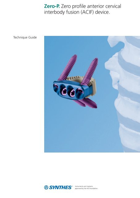
Zero-P. Zero profile anterior cervical interbody fusion (ACIF) device.
Zero-P. Zero profile anterior cervical interbody fusion (ACIF) device.
Zero-P. Zero profile anterior cervical interbody fusion (ACIF) device.
- No tags were found...

You also want an ePaper? Increase the reach of your titles
YUMPU automatically turns print PDFs into web optimized ePapers that Google loves.
Technique Guide<strong>Zero</strong>-P. <strong>Zero</strong> <strong>profile</strong> <strong>anterior</strong> <strong>cervical</strong><strong>interbody</strong> <strong>fusion</strong> (<strong>ACIF</strong>) <strong>device</strong>.
Table of ContentsIntroduction<strong>Zero</strong>-P 2AO Principles 5Indications and Contraindications 6Surgical TechniquePreoperative Planning 7Implant Insertion 8Screw FixationOption A: Aiming Device 12Option B: Drill Guide and Freehand Screw 17Option C: Awl and Freehand Screw 20Option D: Angled Instruments 23Product InformationImplants 26Instruments 28Set 31Dismantling GuideScrewdriver Stardrive 03.617.900 32Holding Sleeve for Screws 03.617.901 33Handle with Quick Coupling 03.617.903 34Awl 2.0 mm, with Sleeve 03.617.990 35Bibliography 36Image intensifier controlWarningThis description is not sufficient for immediate applicationof the instrumentation. Instruction by a surgeon experiencedin handling this instrumentation is highly recommended.Synthes 1
<strong>Zero</strong>-P. <strong>Zero</strong> <strong>profile</strong> <strong>anterior</strong> <strong>cervical</strong><strong>interbody</strong> <strong>fusion</strong> (<strong>ACIF</strong>) <strong>device</strong>.Stand-alone <strong>ACIF</strong> implant<strong>Zero</strong>-P acts as a stand-alone implant for use in <strong>cervical</strong> <strong>interbody</strong><strong>fusion</strong>s 6–12 . Its design combines the functionality of a<strong>cervical</strong> <strong>interbody</strong> spacer and the benefits of an <strong>anterior</strong> <strong>cervical</strong>plate.<strong>Zero</strong> <strong>profile</strong>Reduces risk of dysphagiaThe implant is contained within the excised disc space anddoes not protrude past the <strong>anterior</strong> wall of the vertebralbody as do <strong>anterior</strong> <strong>cervical</strong> plates. This zero <strong>anterior</strong> <strong>profile</strong>may be beneficial in reducing the occurrence and severity ofpostoperative dysphagia 1,2,3,4 .In addition, preparation of the <strong>anterior</strong> surface of thevertebral body is minimized because the implant does not lieagainst this surface.Prevents adjacent level ossificationIt has been shown that <strong>cervical</strong> plates placed near adjacentlevel discs can contribute to bone formation near or aroundthe adjacent level which may lead to future complications 5 .<strong>Zero</strong>-P minimizes this risk, as it remains as far as possiblefrom the adjacent level disc spaces.Ease of use− Because plate and spacer are preassembled, the plate isautomatically aligned upon implant insertion. This avoidsthe process of aligning and realigning an <strong>anterior</strong> <strong>cervical</strong>plate.− The <strong>Zero</strong>-P screws have a one-step locking conical headwhich locks the screw to the plate by simply inserting andtightening the screw.
PEEK <strong>interbody</strong> spacer− Radiopaque marker for posterior visualizationduring imaging− Spacer component is made of pure medicalgrade PEEK Optima ® (Polyetheretherketone)− PEEK Optima does not contain carbon fibersreducing the risk of systematic uptake and localconnective tissue formation− Teeth on the implant surface provide initial stabilityTitanium alloy plate− Provides a secure, rigid screw locking interface− Stresses in plate are decoupled from spacerthrough an innovative interface2.5° 2.5°Locking head screws− Screws form a bone wedge with a 40º ± 5ºcranial/caudal angle and 2.5º medial/lateralangle.− One-step locking screws− Self-tapping screws improve thread purchase− Trilobular thread cutting flutes are self-centering2.5° 2.5°40° 5°40° 5°
Stability similar to that of an<strong>anterior</strong> spacer and plateBiomechanical testing has shown the stability of the implantto be similar to that of traditional plates and spacers.A new stand-alone <strong>cervical</strong> <strong>anterior</strong> <strong>interbody</strong> <strong>fusion</strong><strong>device</strong>: comparison with established <strong>anterior</strong> <strong>cervical</strong>fixation <strong>device</strong>sScholz M, Reyes PM, Schleicher P, Brantley AGU, Baek S,Kandziora F, Marciano F, Crawford NRa b cAbstractStudy design: A new low-<strong>profile</strong> <strong>cervical</strong> <strong>interbody</strong> <strong>fusion</strong>cage with integrated <strong>anterior</strong> fixation was compared biomechanicallyto established <strong>anterior</strong> <strong>cervical</strong> <strong>device</strong>s using nondestructiveflexibility testing in human cadaveric spines.Objective: To evaluate the fixation properties of the newstand-alone <strong>device</strong> (test <strong>device</strong>) and compare these propertieswith established fixation methods under various loadingmodes. The hypothesis is that the new <strong>device</strong> will providestability comparable to that provided by an <strong>anterior</strong> <strong>cervical</strong>cage when supplemented with an <strong>anterior</strong> plate.Methods: Twenty-four human cadaveric C4–C7 <strong>cervical</strong>spines were loaded non-destructively with pure moments ina non-constrained testing apparatus to induce flexion, extension,lateral bending, and axial rotation (maximum 1.5 Nm)while angular motion was measured optoelectronically. Thespecimens were tested:1) intact (N = 24)2) after discectomy and <strong>anterior</strong> stabilizationa) PEEK cage + CSLP [cage+CSLP] (N = 8)b) PEEK cage + Vectra-T [cage+Vectra-T] (N = 8)c) PEEK cage with integrated <strong>anterior</strong> fixation [test <strong>device</strong>](N = 8)3) after ventral plate removal of group 2a and 2b[cage-only] (N = 16).Angle (Degree)9876543210Flexion Extension Axial rotation Lateral bendingIntact Cage stand alone CSLP Vectra-T Test <strong>device</strong>Results: All fixation techniques decreased range of motion(ROM) and Lax Zone (LZ) (P
AO PrinciplesIn 1958, the AO formulated four basic principles, which havebecome the guidelines for internal fixation 13 . They are:– Anatomical reduction– Stable fixation– Preservation of blood supply– Early, active mobilizationThe fundamental aims of fracture treatment in the limbsand <strong>fusion</strong> of the spine are the same. A specific goal in thespine is returning as much function as possible to theinjured neural elements 13 .AO Principles as applied to the spine 14Anatomic reductionIn the spine, this means reestablishing and maintaining thenatural curvature and the protective function of the spine. Byregaining this natural anatomy, the biomechanics of thespine can be improved, and a reduction of pain can be experienced.Stable fixationStabilization of the spinal segment to promote bony <strong>fusion</strong>.Biomechanical tests have demonstrated that the <strong>Zero</strong>-Poffers comparable stability to that of a spacer combined with<strong>anterior</strong> plate fixation in flexion, extension and lateral bending,and torsion.Preservation of blood supplyCreation of an optimal environment for <strong>fusion</strong>.Early, active mobilizationMinimized damage to the spinal vasculature, dura, andneural elements, which may contribute to pain reduction andimproved function for the patient.Synthes 5
Indications and ContraindicationsThe <strong>Zero</strong>-P system is intended for use following <strong>anterior</strong> <strong>cervical</strong>discectomy for reduction and stabilization of the <strong>cervical</strong>spine (C2–C7).Indications include:− Degenerative disc disease (DDD, defined as neck pain ofdiscogenic origin with degeneration of the disc confirmedby history and radiographic studies)− Spinal stenosis− Failed previous <strong>fusion</strong>s− PseudoarthrosisContraindications− Spinal fracture− Spinal tumor− Severe osteoporosis− Spinal infection6 Synthes <strong>Zero</strong>-P Technique Guide
Preoperative PlanningInstrumentsX000069X000070X000071X-ray Template for <strong>Zero</strong>-P, parallelX-ray Template for <strong>Zero</strong>-P, convexX-ray Template for <strong>Zero</strong>-P, lordoticPrior to surgery, determine the desired surgical approach andestimate the appropriate <strong>Zero</strong>-P spacer size. An initial estimateof the size can be made by comparing the x-ray templatefor <strong>Zero</strong>-P with the adjacent intervertebral discs on alateral radiograph.Definitive information on the appropriate size should be obtainedby measuring the distracted disc space during the operationusing the trial spacers.Notes– The height of the spacer indicated on the template is approximately0.8 mm shorter than that of the actual spacerto account for penetration of the teeth into the vertebralend plate.– With the segment fully distracted, the <strong>Zero</strong>-P must fitfirmly between the end plates before locking head screwsare inserted. When rocking the aiming <strong>device</strong> backwardand forward in a cranial to caudal direction, no toggling ofthe implant should be evident.– It is recommended to select the maximum implant size inorder to optimize the stability of the segment through tensionin the annulus fibrosus and longitudinal ligaments.– Template images are 115% of actual implant size to correspondto typical radiographic magnification.Synthes 7
Implant Insertion1ApproachUsing the standard surgical approach, expose the vertebralbodies to be fused. Prepare the <strong>fusion</strong> site following the appropriatetechnique for the given indication.8 Synthes <strong>Zero</strong>-P Technique Guide
2Determine appropriate implantInstruments03.617.720–729 <strong>Zero</strong>-P Trial Spacer, parallel,heights 5–12 mm, purple03.617.750–759 <strong>Zero</strong>-P Trial Spacer, lordotic,heights 5–12 mm, blue03.617.780–789 <strong>Zero</strong>-P Trial Spacer, convex,heights 5–12 mm, goldOptional instruments03.617.940 Handle with Large Quick Coupling03.820.113 MalletSelection of the trial spacer depends on the height of the intervertebralspace, the preparation technique and the patient’sanatomy. Choose a parallel, lordotic or convex trialspacer of the appropriate height.Position the trial spacer in the correct cranial/caudal alignmentand carefully insert it into the disc space.The trial spacers do not have a depth limiter; an image intensifiershould be used to check the position during insertion.With the segment fully distracted, the trial spacer must fittightly and accurately between the end plates.The mallet can be used to help insert and/or remove the trialspacer.If preferred, a larger handle can be attached to the trialspacer.Notes– The trial spacers are color-coded by shape.– The height of the trial spacer is 0.8 mm less than that ofthe corresponding implant to account for penetrationof the teeth into the vertebral end plate.Synthes 9
Implant Insertion3Pack implant with bone graftInstruments03.617.984 Packing Block03.617.970 Cancellous Bone ImpactorPlace the appropriate <strong>Zero</strong>-P implant into the packing block.Use the cancellous bone impactor to firmly pack graft materialinto the implant cavity.Note: To ensure optimal contact with the vertebral endplates it is important to fill the implant until the graft materialprotrudes from the perforations in the spacer.4Insert implantInstrument03.617.963 Aiming DeviceOptional instruments03.617.980 Implant Holder03.820.113 Mallet03.617.981 Impactor, flat03.617.982 Impactor with ball tipUse the aiming <strong>device</strong> or implant holder to introduce the implantinto the disc space. The recommended orientation iswith the medial screws pointing caudally.10 Synthes <strong>Zero</strong>-P Technique Guide
The aiming <strong>device</strong> and the implant holder do not have adepth limiter, therefore an image intensifier should be usedto check the position while inserting.Using the aiming <strong>device</strong>Attach the aiming <strong>device</strong> to the implant by aligning thescrew holes of the implant with the retention features on theaiming <strong>device</strong> and then expanding the aiming <strong>device</strong>. Oncethe implant is securely attached, carefully insert the implantinto the distracted segment.If necessary, the top of the aiming <strong>device</strong> can be tapped withthe mallet to advance the implant into the disc space.If distraction has been applied, release the distraction whileleaving the aiming <strong>device</strong> attached to the implant.Using the implant holderThe implant can be inserted into the disc space with the forceps-typeimplant holder. Once the implant is partially introducedinto the disc space the implant can be advanced tothe correct posterior depth using the flat and/or the impactorwith ball tip.Important: Verify final implant position relative to the vertebralbodies in the AP and lateral direction with the help of anintraoperative x-ray. The PEEK spacer has a single posterior x-ray marker incorporated into the implant to enable accurateintraoperative radiographic assessment of the implant position.Note: The recommended orientation for the implant is withthe medial screws pointing caudally. For convex shaped spacersthis is the only orientation possible.Synthes 11
Screw FixationOption A: Aiming DeviceThe aiming <strong>device</strong> allows one screw to be inserted with the instrumentattached to the implant. This helps to keep the implantin place while the other screw holes are prepared and screws inserted.A1Drill first pilot hole through drill and screw hole ofaiming <strong>device</strong>40° 5°2.5° 2.5°Instruments03.617.963 Aiming Device03.617.912 Drill Bit 2.0 mm, drilling depth 12 mm,3-flute, for Quick Coupling03.617.914 Drill Bit 2.0 mm, drilling depth 14 mm,3-flute, for Quick Coupling03.617.916 Drill Bit 2.0 mm, drilling depth 16 mm,3-flute, for Quick Coupling03.617.903 Handle with Quick Coupling40° 5°2.5° 2.5°Select a drill bit of appropriate length. Insert the drill bit intothe drill and screw hole of the aiming <strong>device</strong> and drill untilthe stop on the drill bit contacts the guide. Intraoperative imagingshould be used to verify drill position.Remove drill bit.Note: The drill bits are marked with a colored ring correspondingto the color-coded screw lengths.Caution: When using the drill bit in combination with theaiming <strong>device</strong>, take care to apply only axial forces to the drillbit. Bending forces applied when the tip of the drill bit is engagedin the aiming <strong>device</strong> can lead to the drill bit breaking.12 Synthes <strong>Zero</strong>-P Technique Guide
A2Insert first screwInstruments03.617.902 Screwdriver Shaft Stardrive, T8,self-holding03.617.903 Handle with Quick CouplingOptional instrument03.617.901 Holding Sleeve for ScrewsSelect the appropriate screw length according to the preoperativeplanning and intraoperative findings.Load a screw onto the screwdriver. The screw will self-retainto the screwdriver, however, for increased screw retentionthe holding sleeve may be used.Advance the screw until the head of the screw contacts theplate.Intraoperative imaging should be used to verify screw position.Caution: The screws should be tightened only after allscrews have been inserted.Synthes 13
Screw FixationOption A: Aiming DeviceA3Drill remaining pilot holesInstruments03.617.963 Aiming Device03.617.912 Drill Bit 2.0 mm, drilling depth 12 mm,3-flute, for Quick Coupling03.617.914 Drill Bit 2.0 mm, drilling depth 14 mm,3-flute, for Quick Coupling03.617.916 Drill Bit 2.0 mm, drilling depth 16 mm,3-flute, for Quick Coupling03.617.903 Handle with Quick CouplingSelect a drill bit of appropriate length. Insert the drill bit intoa drill hole of the aiming <strong>device</strong> and drill until the stop on thedrill bit contacts the guide.Remove the drill bit.Repeat for the remaining screw holes.Note: The drill bits are marked with a colored ring correspondingto the color-coded screw lengths.Caution: When using the drill bit in combination with theaiming <strong>device</strong>, take care to apply only axial forces to the drillbit. Bending forces applied when the tip of the drill bit is engagedin the aiming <strong>device</strong> can lead to the drill bit breaking.14 Synthes <strong>Zero</strong>-P Technique Guide
A4Insert remaining screwsInstruments03.617.902 Screwdriver Shaft Stardrive, T8,self-holding03.617.903 Handle with Quick CouplingOptional instrument03.617.901 Holding Sleeve for ScrewsRemove the aiming <strong>device</strong> from the implant.Load the selected screw onto the screwdriver. The screw willself-retain to the screwdriver, however, for increased screwretention the holding sleeve may be used.Advance screw until the head of the screw is seated in theplate.Repeat for remaining screws.Note: If the aiming <strong>device</strong> is difficult to remove, verify thatthe screw is advanced far enough so that the aiming <strong>device</strong>is not contacting the screw during removal.Synthes 15
Screw FixationOption A: Aiming DeviceA5Tighten screwsInstruments03.110.002 Torque Limiter, 1.2 Nm,with AO/ASIF Quick Coupling03.617.902 Screwdriver Shaft Stardrive, T8,self-holding03.617.903 Handle with Quick CouplingTighten each screw to at least 1.2 Nm torque to fully seatand lock the screw head in the plate.Note: It may be necessary (e. g. screw placed off angle) toapply a higher force than 1.2 Nm to fully seat the screw intothe plate. In such cases, the screwdriver should be used withoutthe torque limiter.16 Synthes <strong>Zero</strong>-P Technique Guide
Screw FixationOption B: Drill Guide and FreehandScrewB1Drill first pilot hole40° 5°2.5° 2.5°Instruments03.617.962 Drill Guide with Handle03.617.912 Drill Bit 2.0 mm, drilling depth 12 mm,3-flute, for Quick Coupling03.617.914 Drill Bit 2.0 mm, drilling depth 14 mm,3-flute, for Quick Coupling03.617.916 Drill Bit 2.0 mm, drilling depth 16 mm,3-flute, for Quick Coupling03.617.903 Handle with Quick Coupling40° 5°2.5° 2.5°It is recommended that the first hole be created for a caudallypointing screw.Select a drill bit of appropriate length. Determine the entrypoint and trajectory for the screw. The correct angulationsfor the screws are 40° in the caudal or cranial direction. Themedial screws point 2.5° laterally and the lateral screws point2.5° medially.Note: Lateral screws should always point medially.Insert the drill guide into the screw hole at the appropriateangle. The tip of the drill guide is designed to fit inside thescrew hole of the plate and provide a “feel” for the correctangle.Insert the drill bit into the guide and drill until the stop onthe drill bit contacts the guide.Remove the drill bit and guide.ImportantIntraoperative imaging should be used to verify drill position.Note: The drill bits are marked with a colored ring correspondingto the color-coded screw lengths. When the ring isflush with the top of the drill guide the appropriate depthhas been reached.Synthes 17
Screw FixationOption B: Drill Guide and Freehand ScrewB2Insert first screwInstruments03.617.901 Holding Sleeve for Screws03.617.902 Screwdriver Shaft Stardrive,T8, self-holding03.617.903 Handle with Quick CouplingSelect the appropriate screw length according to the preoperativeplanning and intraoperative findings.Load a screw onto the screwdriver. Advance the screw untilthe head of the screw contacts the plate.Intraoperative imaging should be used to verify screwposition.18 Synthes <strong>Zero</strong>-P Technique Guide
B3Insert remaining screwsRepeat steps B1 and B2 for the remaining screws.B4Tighten screwsInstruments03.110.002 Torque Limiter, 1.2 Nm, with AO/ASIFQuick Coupling03.617.902 Screwdriver Shaft Stardrive, T8,self-holding03.617.903 Handle with Quick CouplingTighten each screw to at least 1.2 Nm torque to fully seatand lock the screw head in the plate.Note: It may be necessary (e. g. screw placed off angle) toapply a higher force than 1.2 Nm to fully seat the screw intothe plate. In such cases, the screwdriver should be used withoutthe torque limiter.Synthes 19
Screw FixationOption C: Awl and Freehand ScrewC1Awl first pilot hole40° 5°2.5° 2.5°Instrument03.617.990 Awl 2.0 mm, with SleeveIt is recommended that the first hole be created for a caudallypointing screws.40° 5°2.5° 2.5°Determine the entry point and trajectory for the screw. Thecorrect angulations for the screws are 40° in caudal or cranialdirection. The medial screws point 2.5° laterally and thelateral screws point 2.5° medially.Note: Lateral screws should always point medially.Insert the awl at the appropriate angle into a screw hole inthe plate and push down, while simultaneously twisting thehandle.Remove the awl, maintaining alignment of the hole andplate.Important: Intraoperative imaging should be used to verifyawl position.Note: The tip of the awl is designed to fit inside the screwhole of the plate and provide a “feel” for the correct angle.Caution: Take care that the awl does not move the implantrelative to the vertebral body. For particularly hard bone,drilling is recommended to minimize implant movement.20 Synthes <strong>Zero</strong>-P Technique Guide
C2Insert first screwInstruments03.617.902 Screwdriver Shaft Stardrive, T8,self-holding03.617.903 Handle with Quick CouplingOptional instrument03.617.901 Holding Sleeve for ScrewsSelect the appropriate screw length according to the preoperativeplanning and intraoperative findings.Load the screw onto the self-holding screwdriver. The screwwill self-retain to the screwdriver, however, for increasedscrew retention the holding sleeve may be used.Advance the screw until the head of the screw contacts theplate. Intraoperative imaging should be used to verify screwposition.Synthes 21
Screw FixationOption C: Awl and Freehand ScrewC3Insert remaining screwsRepeat step C1 and C2 for the remaining screws.C4Tighten screwsInstruments03.110.002 Torque Limiter, 1.2 Nm,with AO/ASIF Quick Coupling03.617.902 Screwdriver Shaft Stardrive, T8,self-holding03.617.903 Handle with Quick CouplingTighten each screw to at least 1.2 Nm torque, to fully seatand lock the screw head in the plate.Note: It may be necessary (e. g. screw placed off angle) toapply a higher force than 1.2 Nm to fully seat the screw intothe plate. In such cases the screwdriver should be used withoutthe torque limiter.22 Synthes <strong>Zero</strong>-P Technique Guide
Screw FixationOption D: Angled InstrumentsFor screws that are difficult to drill or insert because of interferinganatomy, the angled awl and angled screwdriver maybe used.D1Awl first pilot hole40° 5°2.5° 2.5°Instrument03.617.993 Awl 2.0 mm, angled40° 5°It is recommended that the first hole be created for a caudallypointing screws.2.5° 2.5°Determine the entry point and trajectory for the screw. Thecorrect angulations for the screws are 40° in the caudal orcranial direction. The medial screws point 2.5° laterally andthe lateral screws point 2.5° medially.Note: Lateral screws should always point medially.Insert the awl at the appropriate angle into the screw hole ofthe plate and apply force in the direction of the awl tip whilesimultaneously rotating the handle back and forth.Remove the awl, maintaining alignment of the hole andplate.Important: Intraoperative imaging should be used to verifyawl position.Synthes 23
Screw FixationOption D: Angled InstrumentsD2Insert first screwInstrument03.617.900 Screwdriver Stardrive, T8, self-holding,angled, with SleeveSelect the appropriate screw length according to the preoperativeplanning and intraoperative findings.Load a screw onto the angled screwdriver. Advance thescrew until the head of the screw contacts the plate.Intraoperative imaging should be used to verify screw position.24 Synthes <strong>Zero</strong>-P Technique Guide
D3Insert remaining screwsRepeat steps D1 and D2 for the remaining screws.D4Tighten screwsInstruments03.617.900 Screwdriver Stardrive, T8, self-holding,angled, with Sleeve03.110.002 Torque Limiter, 1.2 Nm, with AO/ASIFQuick Coupling03.617.902 Screwdriver Shaft Stardrive, T8,self-holding03.617.903 Handle with Quick CouplingTighten each screw to at least 1.2 Nm torque, to fully seatand lock the screw head in the plate.Note: It may be necessary (e. g. screw placed off angle) toapply a higher force than 1.2 Nm to fully seat the screw intothe plate. In such cases the screwdriver should be used withoutthe torque limiter.Synthes 25
Implants<strong>Zero</strong>-P Spacers– Supplied sterile and preassembled (spacer with <strong>anterior</strong>fixation plate)– Available in 3 different shapes: convex, lordotic and parallel– Available in two material combinations:1. Spacer component PEEK Optima, plate componenttitanium alloy (TAN)2. Spacer and plate component: Titanium alloy (TAN)– TAN spacer components and trial spacers are color-coded(convex – gold, lordotic – blue, parallel – purple)1. <strong>Zero</strong>-P, spacer component PEEK Optima, plate component TANConvex Lordotic ParallelImplant Implant Trial spacer Implant Trial spacer Implant Trial spacerheight5 mm 04.617.135S 03.617.785 04.617.125S 03.617.755 04.617.115S 03.617.7256 mm 04.617.136S 03.617.786 04.617.126S 03.617.756 04.617.116S 03.617.7267 mm 04.617.137S 03.617.787 04.617.127S 03.617.757 04.617.117S 03.617.7278 mm 04.617.138S 03.617.788 04.617.128S 03.617.758 04.617.118S 03.617.7289 mm 04.617.139S 03.617.789 04.617.129S 03.617.759 04.617.119S 03.617.72910 mm 04.617.130S 03.617.780 04.617.120S 03.617.750 04.617.110S 03.617.72011 mm 04.617.131S 03.617.781 04.617.121S 03.617.751 04.617.111S 03.617.72112 mm 04.617.132S 03.617.782 04.617.122S 03.617.752 04.617.112S 03.617.72226 Synthes <strong>Zero</strong>-P Technique Guide
2. <strong>Zero</strong>-P, spacer and plate component TAN, color-codedConvex Lordotic ParallelImplant Implant Trial spacer Implant Trial spacer Implant Trial spacerheight5 mm 04.617.195S 03.617.785 04.617.185S 03.617.755 04.617.175S 03.617.7256 mm 04.617.196S 03.617.786 04.617.186S 03.617.756 04.617.176S 03.617.7267 mm 04.617.197S 03.617.787 04.617.187S 03.617.757 04.617.177S 03.617.7278 mm 04.617.198S 03.617.788 04.617.188S 03.617.758 04.617.178S 03.617.7289 mm 04.617.199S 03.617.789 04.617.189S 03.617.759 04.617.179S 03.617.72910 mm 04.617.190S 03.617.780 04.617.180S 03.617.750 04.617.170S 03.617.72011 mm 04.617.191S 03.617.781 04.617.181S 03.617.751 04.617.171S 03.617.72112 mm 04.617.192S 03.617.782 04.617.182S 03.617.752 04.617.172S 03.617.7223. Cervical spine locking screws, 3 mm– Self-tapping– Self-centering– Titanium alloy (TAN)– Screw lengths are color coded:12 mm, light blue14 mm, gold16 mm, purpleArt. No. Length Color04.617.812 12 mm Blue04.617.814 14 mm Gold04.617.816 16 mm PurpleSynthes 27
Instruments03.617.720–729 <strong>Zero</strong>-P Trial Spacer, parallel,heights 5–12 mm03.617.750–759 <strong>Zero</strong>-P Trial Spacer, lordotic,heights 5–12 mm03.617.780–789 <strong>Zero</strong>-P Trial Spacer, convex,heights 5–12 mm03.617.900 Screwdriver Stardrive, T8, self-holding,angled, with Sleeve03.617.901 Holding Sleeve for Screws for use withNo. 03.617.90203.617.902 Screwdriver Shaft Stardrive, T8,self-holding03.617.903 Handle with Quick Coupling03.617.912 Drill Bit 2.0 mm, drilling depth 12 mm,3-flute, for Quick Coupling03.617.914 Drill Bit 2.0 mm, drilling depth 14 mm,3-flute, for Quick Coupling03.617.916 Drill Bit 2.0 mm, drilling depth 16 mm,3-flute, for Quick Coupling28 Synthes <strong>Zero</strong>-P Technique Guide
03.617.962 Drill Guide with Handle03.617.963 Aiming Device03.617.970 Cancellous Bone Impactor03.617.981 Impactor, flat03.617.982 Impactor with ball tip03.617.984 Packing Block03.617.990 Awl 2.0 mm, with Sleeve03.617.993 Awl 2.0 mm, angledSynthes 29
Instruments03.110.002 Torque Limiter, 1.2 Nm, with AO/ASIFQuick CouplingOptional instruments03.617.940 Handle with Large Quick Coupling03.617.980 Implant Holder03.820.113 Mallet30 Synthes <strong>Zero</strong>-P Technique Guide
Set68.617.000 Vario Case for <strong>Zero</strong>-P, without Contents(Contains one screw and one trail spacermodule 68.617.001 and 68.617.002)68.617.001 <strong>Zero</strong>-P Module for Screws68.617.002 <strong>Zero</strong>-P Module for Trial Spacers68.000.101 Lid 1 ⁄1 size684.060 Lid 1 ⁄2 size68.000.102 Lid 1 ⁄4 sizeSynthes 31
Screwdriver Stardrive ® , T8, self-holding, angled, with Sleeve 03.617.9001122123432 Synthes <strong>Zero</strong>-P Technique Guide
Holding Sleeve for Screws for use with No. 03.617.902 03.617.901123Synthes 33
Handle with Quick Coupling 03.617.9031234 Synthes <strong>Zero</strong>-P Technique Guide
Awl 2.0 mm, with Sleeve 03.617.9901212Synthes 35
Bibliography1. Bazaz R, Lee MJ, Yoo JU (2002) Incidence of dysphagia after<strong>anterior</strong> <strong>cervical</strong> spine surgery: a prospective study. Spine27:2453–2458.2. Smith-Hammond CA, New KC, Pietrobon R et al. (2004)Prospective analysis of incidence and risk factors of dysphagiain spine surgery patients: comparison of <strong>anterior</strong> <strong>cervical</strong>,posterior <strong>cervical</strong>, and lumbar procedures. Spine 29:1441–1446.3. Lee MJ, Bazaz R, Furey CG et al. (2005) Influence of <strong>anterior</strong><strong>cervical</strong> plate design on Dysphagia: a 2-year prospectivelongitudinal follow-up study. J.Spinal Disord.Tech.18:406-409.11. Mobbs RJ, Rao P, Chandran NK (2007) Anterior <strong>cervical</strong>discectomy and <strong>fusion</strong>: analysis of surgical outcome with andwithout plating. J.Clin.Neurosci. 14:639–6342.12. Moftakhar R, Trost GR (2004) Anterior <strong>cervical</strong> plates: ahistorical perspective. Neurosurg.Focus.;16:E813. Müller ME, Allgöwer M, Schneider R, Willenegger H(1995) Manual of Internal Fixation. 3rd, exp. a. completelyrev. ed. 1991. Corr. 3rd printing. Berlin, Heidelberg, NewYork: Springer14. Aebi M, Arlet V, Webb JK (2007) AOSPINE Manual(2 vols), Stuttgart, New York: Thieme4. Yue WM, Brodner W, Highland TR. (2005) Persistent swallowingand voice problems after <strong>anterior</strong> <strong>cervical</strong> discectomyand <strong>fusion</strong> with allograft and plating: a 5- to 11-year followupstudy. Eur Spine J. 14: 677–6825. Park JB, Cho YS, Riew KD (2005) Development of adjacent-levelossification in patients with an <strong>anterior</strong> <strong>cervical</strong>plate. J.Bone Joint Surg.Am. 87:558–563.6. Kaiser MG, Haid RW Jr., Subach BR et al. (2002) Anterior<strong>cervical</strong> plating enhances arthrodesis after discectomy and<strong>fusion</strong> with cortical allograft. Neurosurgery 50:229–236.7. Barsa P, Suchomel P (2007) Factors affecting sagittalmalalignment due to cage subsidence in standalone cageassisted <strong>anterior</strong> <strong>cervical</strong> <strong>fusion</strong>. Eur.Spine J. 16:1395–1400.8. Herrmann AM, Geisler FH (2004) Geometric results of<strong>anterior</strong> <strong>cervical</strong> plate stabilization in degenerative disease.Spine 29:1226–1234.9. Caspar W, Geisler FH, Pitzen T et al. (1998) Anterior <strong>cervical</strong>plate stabilization in one- and two-level degenerativedisease: overtreatment or benefit? J.Spinal Disord. 11:1–11.10. Fraser JF, Hartl R (2007) Anterior approaches to <strong>fusion</strong> ofthe <strong>cervical</strong> spine: a metaanalysis of <strong>fusion</strong> rates. J.Neurosurg.Spine6:298–303.36 Synthes <strong>Zero</strong>-P Technique Guide
Synthes GmbHEimattstrasse 3CH-4436 Oberdorfwww.synthes.com Presented by:0123036.000.155 SE_158054 AA 50070051 © 05/2008 Synthes, Inc. or its affiliates All rights reserved Synthes and Stardrive are trademarks of Synthes, Inc. or its affiliates