Model: XSD10Z-2 - Y3k.com
Model: XSD10Z-2 - Y3k.com
Model: XSD10Z-2 - Y3k.com
- No tags were found...

Create successful ePaper yourself
Turn your PDF publications into a flip-book with our unique Google optimized e-Paper software.
INDEX21 PRODUCT DESCRIPTION 32 FEATURES 33 INSTALLATION 43.1 Contents 43.2 Install 43.3 Wall Mounting Guide 44 DIP SWITCH SETUP 54.1 Communication Protocol Setup 54.2 Camera ID Setup 54.3 Reserved for Supplier 55 CABLING 65.1 Power Connection 65.2 Camera ID Setup 65.3 Video Connection 75.4 Alarm Input Connection 76 OPERATION 86.1 Starting OSD Menu 96.2 Reserved Preset 96.3 Preset 96.4 Swing 96.5 Pattern 106.6 Group 106.7 Other Functions 116.8 OSD Display Of Main Screen 117 MENU FUNCTIONS 127.1 Main Menu 127.2 Display Setup 127.2.1 Set North Direction 137.2.2 Privacy Zone Mask Setup 137.3 Camera Setup 147.3.1 White Balance Setup 147.3.2 Auto Exposure Setup 147.4 Motion Setup 157.4.1 Parking Action Setup 167.4.2 Alarm Input Setup 167.5 Preset Setup 177.5.1 Edit Scene Preset 177.5.2 Edit Preset Label 187.6 Swing Setup 187.7 Pattern Setup 197.7.1 Edit Pattern 197.8 Group Setup 207.8.1 Edit Group 207.9 Initialize system 217.9.1 Initial Configuration Settings 218 SPECIFICATIONS 22
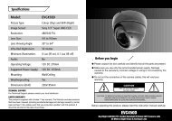
1. Product DescriptionThe <strong>XSD10Z</strong>-2 is a Professional True Day/Night Speed Dome with 10x Zoom with Mechanical IR Filter (making it IR sensitive foruse with Infra Red lighting). This camera is designed for use in very high risk applications where very high quality surveillance isrequired and features an Xvision Auto Iris Zoom Lens with Semi-Auto or Auto Focus and 100x Zoom (10x Optical + 10x Digital)for easy selection of any viewing angle between 10 and 71°. It can be panned, tilted and zoomed in seconds to the view required.It is ideal for covering large areas and for viewing objects that are far away from the camera or for viewing moving objects thatare at varying distances from the camera thanks to its 10x Optical zoom and auto focus function. The camera has an RS485connection allowing the Pan, Tilt, Zoom, Focus and On Screen Display set up of its features to be controlled remotely by any DVRor Controller that supports Pelco D/P. It is weatherproof allowing it to be used internally or externally.A variety of brackets are available for the camera depending on how and where you wish to mount it. Mounting options includeCeiling Mount (as supplied), Wall Mount, Corner and Pole Mount (additional brackets required).2. Features• z True Day/Night Camera with Sony 1/4” Super HAD CCD and Xvision XX1 DSP Software• z Offers High Resolution 550/600 TVL images• z Features 3.8 to 38.0mm Auto Iris Zoom Lens for 10 to 71° adjustable angle of view• z Zoom Magnification :×10 Optical Zoom,×10 Digital Zoom (Max×100 Zoom)• z Supports various Focus Modes : Auto-Focus / Manual Focus / Semi-Auto Focus.• z Vector Drive Technology and Hi-accuracy motor drives with 0.05 degree preset accuracy per second, without any vibration.• z Pan Range: 360°(Endless), Tilt Range: 180°(Auto-Flip), 95° (Normal)• z 0.05~360°/sec manual Pan/Tilt Speed• z 1~180°/sec Swing speed• z Supports up to 128 presets. The characteristics of each preset can be set up independently.• z Up to 8 Pan Actions can be stored. This enables to move camera repetitively between two preset positions with a designatedspeed.• z Up to 4 Patterns can be recorded and played back. This enables to move camera to follow any trajectory operated by joystick.Up to 1200 <strong>com</strong>mands per pattern can be stored.• z Up to 8 group actions can be stored. This enables to move camera repetitively with <strong>com</strong>bination of Preset or Pattern or Swing.A Group is <strong>com</strong>posed of up to 20 entities of Preset/Pattern/Swings.• z Up to 4 Privacy Zones are assignable.• z 4 Alarm Sensor inputs are available for the camera to move to a corresponding Preset position if triggered. The alarm sensorInput is de-coupled with photo coupler to reject external electric noise and shock.• z With RS485 <strong>com</strong>munication, up to 255 cameras can be controlled at the same time.• z Pelco-D or Pelco-P protocol can be selected as a control protocol in the current version of firmware.• z On-Screen Display Menu for Programmable Functions and to display the status of camera• z OSD Menu can be customized to suit user• z Designed for Flush/Surface ceiling mounting as supplied• z Wall, Pole Mount and Corner Mount brackets also available.• z Suitable for internal or external use.3
3. Installation3.1 CONTENTS• z <strong>XSD10Z</strong>-2 Dome• z Installation Bracket• z 2.5mm Flat Head Screw Driver• z Allun Key• z Opening Tool• z 4x Wall Plugs and Screws - for ceiling mount3.2 INSTALLATION1. Dismantle the lower cover <strong>com</strong>ponents of the transparent dome cover with Allun Key2. Drill holes in the ceiling according to the mounting hole position and install the plastic anchor.3. Feed the control cable, video cable and power cable through the ceiling4. Fix the dome base and the transparent dome cover, screw tightly to <strong>com</strong>plete the installation as shown below.114mmØ=150mm50mm4Installation Holes3.3 WALL MOUNTING GUIDENOTE: THE WALL MOUNT IS NOT SUPPLIED WITH THE <strong>XSD10Z</strong>-2.1. Drill holes on the wall using the mounting hole position, and install the plastic anchor to the wall mount.2. Feed the control cable, video cable and power cable through the wall bracket cavity3. Align the dome camera to the bracket’s holes then rotate the dome camera clockwise and fix the backstop screw.4. Feed the control cable, video cable and power cable through the wall hole and fix the bracket using the screws and wallplugs supplied.12mm6mmØ=137mm120°Wall Bracket Installation Holes
4. DIP Switch SetupBefore you install the camera, you should set the DIP switches to configure the camera ID and <strong>com</strong>munication protocol.COMMUNICATION PROTOCOLCAMERA IDOPTIONSADDRESS (ID)ONON1 2 3 41 2 3 4 5 6 7 8PIN 1 2 3 4FUNCTION PROTOCOL N/P ONPIN 1 2 3 4 5 6 7 8FUNCTION A0 A1 A2 A3 A4 A5 A6 A7ONOFFRefer to the ManualPALNTSOReserveON 1 2 4 8 16 32 64 128OFF 0 0 0 0 0 0 0 04.1 COMMUNICATION PROTOCOL SETUP• z Select the appropriate Protocol with DIP switch <strong>com</strong>binationSWITCH STATE 3P0 (PIN 1) P1 (PIN 2)OFF OFF PELCO_D, 2400 bpsON OFF PELCO_D, 9600 bps5OFF ON PELCO_P, 4800 bpsON ON PELCO_P, 9600 bps• z If you want to control using DVR or P/T controller, their protocol must be identical to camera. Otherwise, you can not controlthe camera.• z If you changed camera protocol by changing DIP switch, the change will be effective after you reboot the camera.• z The factory default of protocol is Pelco-D, 2400 bps4.2 CAMERA ID SETUP• z ID number of camera is set using binary number. The example is shown bellow.• z The range of ID is 1~255. Do not use 0 as camera ID. Factory default of Camera ID is 1.• z If you want to control a certain camera, you must match the camera ID with Cam ID setting of DVR or Controller.4.3 RESERVED FOR SUPPLIERON1 2 3 4 5 6 7 8• z Since Pin 3 and Pin 4 are only for the supplier. Do not change their original state. If you change one of these, full operationcannot be achieved• z Pin 3 - PAL / NTSC system selection of Camera. Do not change this pin.• z Pin 4 - Factory default is ON state. This pin is used for system firmware upgrade. Do not change this pin .
5. CablingBefore you install the camera, you should set the DIP switches to configure the camera ID and <strong>com</strong>munication protocol.Cable Terminal BlockIN 1IN 2IN 3IN 4IN COM+J5J6VIDEO-VIDEO+RS-485+RS-485-PWR-PWR+FANHOTIrDASensorDoorSwitchSENSOR5.1 POWER CONNECTION• z Please check the voltage and current capacity of rated power carefully.• z Rated power is indicated in the back of main unit.6POWER INPUT VOLTAGE RANGE CURRENT CONSUMPTION12V 11-18V DC 0.8A5.2 CAMERA ID SETUP• z For PTZ control, connect the cabling to the keyboard and DVR.• z To control multiple cameras at the same time, they should be connected in a parallel circuit as shown below.RS485+ -+ - + -#1 #2 #n
5.3 VIDEO CONNECTION• z Connect with BNC Coaxial Cable5.4 ALARM INPUT CONNECTION (Optional)• z Sensor InputBefore connecting sensors, check driving voltage and output signal type of the sensor. Since output signal types of the sensorsare divided into Open Collector and Voltage Output type in general,the cabling must be done properly after considering thesetyped.IN COM+SIGNALIN1-, IN2-, IN3-, IN4-DESCRIPTIONConnect (+) cable of electric power source for Sensors to this port as shown in the circuit above.Connect output of sensors for each port as shown in the circuit above.If you want to use Alarm Input,the types of sensor must be selected in OSD menu. The sensor types are Normal Open andNormal. It sensor type is not selected properly, the alarm can be activated reversely.7Normal OpenNormal CloseOutput Voltage is high state when sensor is activatedOutput Voltage is high state when sensor is not activated
6. OperationCheck points before operation• z Before power is applied, please check the cables carefully.• z The camera ID of the controller must be identical to that of the target camera. The camera ID can be checked by reading theDIP switch of the camera.• z If your controller supports multi-protocols, the protocol must be changed to match to that of the camera.• z If you changed camera protocol by changing DIP switch the change will be effective after you reboot the camera• z Since the operation method can be different for each controller available refer to the manual for your controller if camera cannot be controlled properly. The operation of this manual is based on the standard Pelco R Controller.Preset and pattern Function Pre-Check• z Check how to operate the preset and pattern functions with controller or DVR in advance to operate camera functions fulIywhen using controller or DVR.• z Refer to the following table when using standard Pelco protocol controller.Input [Preset Number] and press [Preset] button.Input [Preset Number] and press [Preset] button for more than 2 seconds.Input [Pattern Number] and press [Preset] button.Input [Pattern Number] and press [Preset] button for more than 2 seconds.z • If controller or DVR has no pattern button or function, use the shortcut keys with preset numbers. For more information, referto ’Reserved Preset’ in this manual.8
6.1 STARTING OSD MENUUsing the OSD menu, Preset, Pattern, Swing, Group and Alarm Input function can be configured for each application.• z Enter Menu -6.2 RESERVED PRESET[95]Some Preset numbers are reserved to special functions. [95] :Enters into OSD menu [131~134] :Runs Pattern Function 1~4 [141-148] :Runs Swing Function 1~8 [151-158] :Runs Group Function l~8 [161-162] :Sets Relay Output 1 ~ 2 to OFF[161-162] :Sets Relay Output l ~ 2 to ON [170] :Sets Camera BLC Mode to OFF [17 1] :Sets Camera BLC Mode to ON [174] :Sets Camera Focus Mode to AUTO [175] :Sets Camera Focus Mode to Manual [176] :Sets Camera Focus Mode to SEMI-AUTO [177] :Sets Day/Night Mode to AUTO [178] :Sets Day & Night Mode to NIGHT [179] :Sets Day & Night Mode to DAY [190] :Sets OSD Display Mode to AUTO (Except Privacy Mask) [191] :Sets OSD Display Mode to OFF (Except Privacy Mask) [192] :Setting OSD Display Mode to ON (Except Privacy Mask) [193] :Sets all Privacy Mask Display to OFF [194] :Sets all Privacy Mask Display to ON96.3 PRESETA maximum of 127 positions can be stored as Preset position. The Preset number can be assigned from 1 to 128, but 95 isreserved for starting OSD menu. Camera characteristics (White Balance, Auto Exposure) can be set up independently for eachpreset. Label should be blank and ’Camera Adjust’ should be set to ‘GLOBAL’ as default. All characteristics can be set up in theOSD menu.• z Set Preset• z Run Preset• z Delete Preset6.4 SWING[1~128][1~128]To delete Preset, use OSD menu.By using the Swing function, you can make camera to move between 2 Preset positions repeatedly. When swing function runs,camera moves from the preset assigned as the 1st point to the preset assigned as the 2nd point in a CW (Clockwise) direction.Then camera moves from the preset assigned as the 2nd point to the preset assigned as the 1st point in CCW (Counterclockwise)direction.If the preset assigned for the Pan function is same for both point, the camera turns on its axis by 360° in a CW (Clockwise)direction and then it turns on its axis by 360° in a CCW (Counterclockwise) direction.Speed can be set up from 1°/second to 180°/second.• z Set PresetTo set Pan, use the OSD menu• z Run Preset Run Swing 1: [141] Run Swing 2: [142]Run Swing 3: [143] Run Swing 4: [144]• z Delete PresetTo delete Swing,use OSD menu.
6.5 PATTERNThe Pattern Function allows the camera to follow a user defined trajectory set by a joystick or controller for an assigned timepath. 4 Patterns are available and a maximum of 1200 <strong>com</strong>munication <strong>com</strong>mands can be stored per pattern.• z Set PatternPattern can be created by following the steps below:--Enter OSD Menu > Pattern Setup--Pattern editing screen is displayed as below.EDIT PATTERN[NEAR:SAVEFAR:DELETE]0/0/×1/N--Move the Joystick and preset movement will be memorised in a pattern.--The rest memory size is displayed in progress bar.--To save the recording, press NEAR key and to cancel, press FAR key• z Run Preset Run Pattern 1: [131] Run Pattern 2: [132]Run Pattern 3: [133] Run Pattern 4: [134]Delete PresetTo delete Pattern, use OSD menu.106.6 GROUPThe group function allows the running sequence of Presets, Pattern and/or Swings. A maximum of 8 groups can be stored. Eachgroup can have a maximum of 20 action entities which can be preset, pattern or swing. Preset speed, the repeat number ofPattern/Swing and dwell times between actions can be set up in Group setup.Dwell TimePreset 1 Preset 2 Swing 1• z Set PresetTo set a Group, use the OSD menu• z Run Preset Run Group 1: [151] Run Group 2: [152]Run Group 3: [153] Run Group 4: [154]• z Delete PresetTo delete Group, use OSD menu.Maximum of 20
6.7 OTHER FUNCTIONS• z Power Up Action• z Auto Flip• z Parking Action• z Alarm Input (Optional)This function enables to resume the last action executed before power down. Most of actions suchas Preset, Pattern, Swing and Group are available for this function but jog actions are not availableto resumeIn case that tilt angle arrives at the top of tilt orbit (90°), zoom module camera keep moving toopposite tilt direction (180°) to keep tracing targets. As soon as zoom module camera passesthrough the top of tilt direction(90°) images should be reversed automatically and F appears inscreen. If this function is set to OFF, the tilt movement range is 0-95°.This function enables to locate the camera to specific position automatically if operator doesn’toperate the controller for a while. The Park Time can be defined as an interval from 1 minute to 4hours.4 Alarm Inputs are used. If an external sensor is activated,camera can be set to move tocorresponding preset position. It is noted that the latest alarm input is effective if multiple sensorsare activated.• z Privacy Zone MaskTo protect privacy, MAX. 4 Privacy Masks can be created on the arbitrary position to hide objectssuch as windows, shops or private house. With Spherical Coordinates system, powerful Privacy ZoneMask function is possible• z GLOBAL/LOCAL Image SetupWB(White Balance) and AE (Auto Exposure) can be set up independently for each preset. There are2 modes, ‘Global’ mode, ‘Local’ mode. The Global mode means that WB or AE can be set up totallyand simultaneously for all presets in ‘ZOOM CAMERA SETUP’ menu. The Local mode means thatWB or AE can be set up independently or separately for each preset in each preset setup menu. EachLocal WB/AE value should activate correspondingly when camera arrives at each preset location.During jog operation, Global WB/AE value should be applied. All Local WB/AE value do not changealthough Global WB/AE value changes.SemiAuto FocusThis mode exchanges focus mode automatically between Manual Focus mode and Auto Focus modeby operation. Manual Focus mode activates in preset operation and Auto Focus mode activatesduring jog operation With Manual mode at presets, Focus data is remembered in each preset inadvance and camera calls focus data in correspondence, Focus mode changes to Auto Focus modeautomatically when jog operation starts.116.8 OSD DISPLAY OF MAIN SCREENPreset LabelLABEL 12345PRESET1Action TitleImage FlipCamera IDFCAM1I:1--415/4/×1/NAlarm InformationP/T/Z Information• z P/T/Z Information• z Camera ID• z Action Title• z Preset Label• z Alarm Input (Optional)• z Image FlipCurrent Pan/Tilt angle in degree, zoom magnification and a <strong>com</strong>pass directionCurrent Camera ID (Address)The following are possible Action-Titles and their meaning.The Label stored for specific PresetThis information shows current state of Alarm Input. If an Input point is ON state it will show anumber corresponding to each point If an Input point is OFF state, ‘ - ‘ will be displayedExample: Point 2 & 3 inputs are ON, OSD will show as:I: -23-Shows if images are currently reversed by the Auto Flip Function
7. Menu FunctionsGeneral Rules of Key Operation for Menu• z The menu items surrounded with ( ) always has its sub menu.• z For aIl menu level, to go into sub menu, press NEAR key• z To go to up-one-level menu, press FAR key.• z To move from item to item in the menu, use the joystick in the Up/Down or Left/Right.• z To change a value of an item, use Up/Down of the joystick in the controller• z Press NEAR key to save values and Press FAR key to cancel Values.7.1 MAIN MENUSPEED DOME CAMERAEXIT12System Information: Displays system information and configuration.Display Setup: Enable/Disable of OSD display on Main ScreenDome Camera Setup: Configure various functions of this camera.System Initialize: Initializes system configuration and sets all data back to factory default configuration7.2 DISPLAY SETUPThis menu defines Enable/Disable of OSD display on Main Screen. If an item is set to AUTO, the item is displayed only when thevalue of it is changed.DISPLAY SETUPCAMERA IDONPTZ INFORMATION AUTOACTION TITLEAUTOPRESET LABELAUTOALARM INPUTAUTOBACKEXITCamera ID: [ON/OFF]PTZ Information: [ON/OFF/AUTO]Action Title: [ON/OFF/AUTO]Preset Label: [ON/OFF/AUTO]Alarm Input: [ON/OFF/AUTO]
7.2.1 Set North DirectionSET NORTH DIRECTIONMOVE TO TARGET POSITION[NEAR: SAVE] [FAR: CANCEL]Go to the function to assign <strong>com</strong>pass direction to north. Move camera and press NEAR button to save.7.2.2 Privacy Zone Mask SetupPRIVACY ZONEMASKNO 1UNDEFINEDDISPLAY OFFCLEARMASK CANCELBACKEXIT• z Mask No. [1~4]Select Mask number. If the selected mask has already data camera moves as it was set. Otherwise “UNDEFINED” will bedisplayed under“Mask No”.• z Display [ON/OFF]Sets if camera mask shows on images• z Clear Mask [CANCEL/OK]Deletes data in the selected Mask No.• z Move camera to the area to mask. Then the menu to adjust mask size will be displayed.13EDIT MASK 1[ : ADJUST MASK WIDTH][ : ADJUST MASK HEIGHT][NEAR: SAVE] [FAR: CANCEL]To adjust mask size, use joystick or arrow buttons to adjust mask size.--Left/Right Adjusts mask width.--Up/Down Adjusts mask height.
7.3 CAMERA SETUPUse this menu to setup the general functions of zoom camera module.ZOOM CAMERA SETUPFOCUS MODEDIGITAL ZOOMLINE LOCKSEMIAUTOONOFFBACKEXITFocus Mode:[AUTO/MANUAL/SEMIAUTO]• z SEMIAUTO Mode exchanges focus mode automatically between Manual Focus mode and Auto Focus mode• z Manual Focus mode activates in preset mode. (Focus data is memorized in each preset in advance and camera calls focus datain correspondence with presets as soon as camera arrives at a preset)• z Auto Focus mode activates when jog operation Starts.Digital Zoom:[ON/OFF]Sets digital zoom function to ON/OFF. If this is set to OFF, optical zoom function runs but zoom function stops at the end ofoptical zoom magnification.Line Lock:[ON/OFF]If Line lock sync is ON, video signal is synchronized with AC power. Video can be adjusted after setting is changed.147.3.1 White Balance SetupWB SETUP - GLOBALWB MODEAUTORED ADJUST ---BLUE ADJUST ---BACKEXIT• z WB Mode [AUTO/MANUAL]In Manual mode, Red and Blue level can be set up manually• z Red Adjust [10-60]• z Blue Adjust [10-60]7.3.2 Auto Exposure SetupAE SETUP - GLOBALBACKLIGHT OFFDAY/NIGHT AUTOBRIGHTNESS 25IRISAUTOSHUTTER ESCAGCNORMALSSNRMIDDLESENG-UP BACKEXIT
• z Backlight [ON/OFF]Sets Bacldight Compensation• z Day/Night [AUTO1/AUT02DAY/NIGHT]AUT01 exchanges Day/Night mode faster than AUT02.• z Brightness [0-100]Adjusts brightness of images. Iris, Shutter Speed and Gain are adjusted automatically in correspondence with this value• z Iris [AUTO/MANUAL(0~100)]if Iris is set to Auto Iris should have highest priority in adjusting AE and Shutter Speed should be fixed. If Iris is set to Manual,Iris should be fixed aa Iris has lower priority in adjusting AE.• z Shutter Speed [ESC/A. Flicker/Manual(x128~1/120000 sec )]If Iris is set to Manual and Shutter Speed is set to ESC,Shutter Speed should have highest priority. If Shutter Speed is set to A.Flicker, to remove Flicker, Shutter Speed should be set to 1/100 for NTSC and 1/120 for PAL.• z AGC [OFF/NORMAL/HIGH]Enhances image brightness automatically if the luminance level of image signal is too low• z SSNR (DNR - Digital Noise Reduction) [OFF/LOW/MIDDLE/HIGH]Enhances images by deducting noises when gain level of images is too high.• z SENS-UP (Dynamic Night View) [AUTO(2-128)/OFF]Activates Slow Shutter function when luminance of Image is too dark. It is possible to set up the maximum number of framespiled up one on another by Slow Shutter function.7.4 MOTION SETUPUse this menu to setup the general functions of zoom camera module.AE SETUP - GLOBALMOTION LOCKOFFPWR UP ACTION ONAUTO FLIPONJOG MAX SPEED 120/SECJOG DIRECTION INVERSEFRZ IN PRESET OFF15BACKEXITMotion Lock:[ON/OFF]If Motion Lock is set to ON, it is impossible to set up and delete Preset, Swing, Pattern and Group. Otherwise it is only possible torun those functions.Power Up Action: [ON/OFF]Refer to “Other Functions” section.Auto Flip:[ON/OFF]Refer to “Other Functions” section.Jog Max Speed: [1/sec - 360/sec]Sets maximum jog speed. Jog speed is inversely proportional to zoom magnification. As zoom magnification goes up, pan/tiltspeed goes downJog Direction:[INVERSE/NORMAL]If you set this to ‘Inverse’ the view in the screen will move in the same direction with jog tilting. If ‘Normal’ is selected, the viewin the screen will move reverselyFreeze in Preset: [ON/OFF]If set to ON, at the start point of preset movement the camera freezes the image of start point and keeps displaying the imageduring the entire preset movement. It does not display the images which the camera gets during the preset movement. As soonas camera stops at preset end point, camera starts displaying live images which it gets at preset end point.
7.4.1 Parking Action SetupPARKING ACTION SETUPPARK ENABLEOFFWAIT TIME 00:10:00PARK ACTIONHOMEBACKEXIT• z Park Enabled [ON/OFF]If Park Enable is set to ON, the camera will run the assigned PTZ function automatically if there is no ‘’Wait Time’’ assigned• z Wait Time [1 minute-4 hours]The time is displayed in HH:MM:SS” format and you can change this by 1 min units.• z Park Action[HOME/PRESET/PATTERN/SWING/GROUP]--Home: Camera moves to home position if there is no PTZ <strong>com</strong>mand during assigned in “Wait Time”.7.4.2 Alarm Input SetupMatch the Alarm sensor input to one of Preset positions. If an external sensor is activated, the camera will move to correspondingpredefined preset position.ALARM INPUT SETUP16ALARM1TYPEALARM2TYPEALARM3TYPEALARM4TYPEALARM1ACTALARM2ACTALARM3ACTALARM4ACTBACKEXITN.OPENN.OPENN.OPENN.OPENNOT USEDNOT USEDNOT USEDNOT USED• z Alarm Type [Normal OPEN/Normal CLOSE]Sets sensor input type.• z Alarm Action [NOT USED/PRESET 1~128]Assign counteraction Preset position to each Alarm input.
7.5 PRESET SETUPUse this menu to setup the general functions of zoom camera module.PRESET SETUPPRESET NO. 1CLEAR PRESETCAM ADJUSTCANCELLABEL123GLOBALBACKEXITPreset Number: [1~128]If a selected preset is already defined, the camera will move to predefined position and preset characteristics such as Label andRelay Outputs will show on the display monitor. If a selected preset is not defined, ‘UNDEFINED’ shows on monitor.Clear Preset:[CANCEL/OK]Deletes current Preset dataEdit Preset Scene: Allows you to edit the current Preset scene positionEdit Preset Label: Edits Label to show on monitor when preset runs. A maximum of 10 letters can be assigned.CAM Adjust: [GLOBAL/LOCAL]WB (White Balance) and AE(Auto Exposure) can be set up independently for each preset.• z Global mode means that WB or AE can be set up fully and simultaneously for all presets in the ‘ZOOM CAMERA SETUP’menu.• z Local mode means that WB or AE can be set up independently or separately for each preset in each preset setup menu. EachLocal WB/AE value should activate correspondingly when the camera arrives at each preset location.• z During jog operation, Global WB/AE value should be applied.• z All Local WB/AE values will not change although Global WB/AE values will change as the settings are changed. If ‘Local’ isselected ‘WB/AE’ will show on the Monitor.177.5.1 Edit Scene PresetEDIT SCENE PRESETMOVE TO TARGET POSITION[NEAR: SAVE] [FAR: CANCEL]Using Joystick, move camera to desired position. Press NEAR key to current PTZ data. Press FAR key to Cancel.
7.5.2 Edit Preset LabelCurrent Cursor positionEDIT PRESET LABEL[_ _ _ _ _ _ _ _ _ _]1 2 3 4 5 6 7 8 9 0 OKA B C D E F G H I J CANCELK L M N O P Q R S TU V W X Y Z a b c de f g h i j k l m no q r s t u v w xy z < > - / : .Space characterIn the Edit Label menu use the Left/Right/Up/Down of the joystick to move to the desired character from the Character set.--To choose the character, press the NEAR key--If you want to use blank, choose Space character (as shown in the diagram above)--If you want to delete a previous character, use the back space character ( )--If you <strong>com</strong>plete the Label editing, move cursor to ‘OK’ and press the NEAR key to save the <strong>com</strong>pleted label.--To cancel any changes, move the cursor to ‘Cancel’ and press the NEAR key.7.6 SWING SETUPSWING SETUP18SWINGING 11ST POSNOT USED2ND POSNOT USEDSWING SPEED30/SECCLEAR SWINGCANCELBACKEXITSwing Number: [1~8]Selects Swing number to edit. If a selected Swing has not been defined, ‘NOT USED’ will display in 1st Position and 2nd Position1st Position: [PRESET 1~128]2nd Position [PRESET 1~128]Set up the 2ND position for Swing function If a selected preset is not defined, ‘UNDEFINED’ will be displayed as shown below:SWING SETUPSWINGING 11ST POSPRESET52ND POSNOT USEDUNDEFINEDSWING SPEED30/SECCLEAR SWINGCANCELBACKEXITWhen swing function runs, the camera will move from the preset assigned as position 1 to the preset assigned as position 2 in aCW (Clockwise) direction. Then the camera will move from position 2 to position 1 in a CCW (Counterclockwise) direction.If the preset assigned as the 1st point is the same as the preset assigned as the 2nd point, the will turn on its axis by 360 in a CWdirection and then it turns on its axis by 360 in a CCW directionSwing Speed[1 /sec~180 /sec]Sets Swing speed from I /sec to 180 /sec.Clear Swing[CANCEL/OK]Deletes current Swing data
7.7 PATTERN SETUPPATTERN SETUPPATTERN 1UNDEFINEDCLR PATTERNCANCELBACKEXITPattern Number: [1~4]Select Pattern number to edit. If a selected pattern number is not defined, ‘UNDEFINED’ will be displayed under the selectedpattern number.Clear Pattern:[CANCEL/OK]Deletes data in current patternEdit Pattern:Allows the selected pattern to be edited.7.7.1 Edit PatternEDIT PATTERN 119[NEAR: SAVE] [FAR: DELETE]0/0/X1/N--By using Joystick, move to the start position with the appropriate zoom.--To start pattern recording, press the NEAR key. (To exit this menu, press the FAR key.)--Move the camera with joystick of controller or run a preset function in a selected pattern which will be recorded.--The total memory size and the remaining memory size will be displayed in the form of a bar. A maximum of 1200<strong>com</strong>munication <strong>com</strong>mands can be stored in a pattern--To save the data and exit, press the NEAR key--To cancel recording and delete the recorded data, press the FAR key.
7.9 INITIALIZE SYSTEMSYSTEM INITIALIZECLEAR ALL DATACLR DISPLAY SETCLR CAMERA SETCLR MOTION SETCLR EDIT DATAREBOOT CAMERAREBOOT SYSTEMNONONONONONONOSAVECANCELClear All Data:Clear Display Set:Clear Camera Set:Clear Motion Set:Clear Edit Data:Reboot Camera:Reboot System:Deletes all configuration data such as Display, Camera, Motion setup and so on.Initializes Display ConfigurationInitializes Camera ConfigurationInitializes Motion ConfigurationDeletes Preset Date, Swing Data, Pattern Data and Group DataReboots Zoom Camera moduleReboots Speed Dome Camera7.9.1 Initial Configuration SettingsDISPLAY CONFIGURATIONCamera ID ONPTZ Information AUTOAction Title AUTOPreset Label AUTOAlarm Input AUTONorth Direction Pan 0°Privacy Zone UndefinedMOTION CONFIGURATIONMotion Lock OFFPower Up Action ONAuto Flip ONJog Max Speed 120°/secJog Direction INVERSEFreeze In Preset OFFPark Action OFFAlarm Action OFFCAMERA CONFIGURATIONFocus Mode SemiAutoDigital Zoom ONLine Lock OFFWhite Balance AUTOBacklight OFFDay&Night AUTO1Brightness 25IrisAUTOShutterESCAGCNORMALSSNRMIDDLESENS-UP AUTO (4 Frame)MOTION CONFIGURATIONPreset 1~128 UndefinedSwing 1~8 UndefinedPattern 1~4 UndefinedGroup 1~8 Undefined21
Appendix 8. Specifications 7: Specifications<strong>Model</strong>:Picture Type:Image Sensor:DSP:Resolution:Minimum Illumination:Lens Type:Lens Size:<strong>XSD10Z</strong>-2True Day/NightSony 1/4” Super HAD CCDXvision XX1550/600 TVL0.005 LuxAuto Iris Varifocal Lens3.8 to 38.0mmLens Viewing Angle: 10 to 71°22Zoom:Audio:Operating Voltage:Suggested Power Supply:Mounting:Weatherproofing:Dimensions (WHD):10x Optical, 10x DigitalNo12V DC 800mASuppliedCeiling (as supplied)Additional mounts & brackets are available for Wall Mount,Corner Mount and Pole Mounting options.Yes150 x 130 x 150mm
TECHNICAL SUPPORT:For Technical Support for any Xvision product please contact your local distributor.LIMITED WARRANTY:This product is supplied with a 1 Year warranty. The Warranty excludes products that have beenmisused, (including accidental damage) and damage caused by normal wear and tear. In the unlikelyevent that you encounter a problem with this product, it should be returned to the place of purchase.24Manufactured exclusively for Xvision - www.x-vision.co.ukUK/EuropeFar EastMiddle EastNorth AmericaXvision Group (UK)Kyoung Am BuildingBurjuman Tower,100 Park AvenueUnit 2, Valley Point,157-27 Samsung-dong18th FloorNew York City,Beddington Farm Road,Kangnam-kuPO Box 121828New YorkCroydon, Surrey135 090 SeoulDubai 4365910017CR0 4WPKoreaUnited Arab EmiratesUnited StatesEmail: sales@x-vision.co.ukEmail: globalsales@x-vision.co.ukEmail: mesales@x-vision.co.ukEmail: usasales@x-vision.co.uk