Module 2a Axial Exp.Joints BOA AG General - BOA Group
Module 2a Axial Exp.Joints BOA AG General - BOA Group
Module 2a Axial Exp.Joints BOA AG General - BOA Group

You also want an ePaper? Increase the reach of your titles
YUMPU automatically turns print PDFs into web optimized ePapers that Google loves.
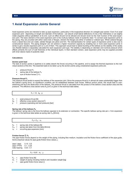
<strong>BOA</strong><strong>Exp</strong>ansion <strong>Joints</strong> Guide1 <strong>Axial</strong> <strong>Exp</strong>ansion <strong>Joints</strong> <strong>General</strong><strong>Axial</strong> expansion joints are intended to take up pipe expansion, particularly in the longitudinal direction of a straight pipe section. Even if an axialexpansion joint - depending on length and diameter of the bellows - can absorb small lateral deflections of only a few millimetres or can slightlyrotate angularly without parallelism at its end, such an effect should not be allowed and should never be the main function of the axial expansionjoint. The basic element of the axial expansion joint is the multi-ply bellows made of austenitic steel. To connect axial expansion joints tothe piping, they are provided with either weld ends or flanges, wherein the flanges are either of welded or collared type. Whilst collared flangeshave a raised face and can rotate, welded flanges are plane and firm. The standardization for certain types of expansion joints is also due toconstructional reasons. The piping designer can not achieve a higher movement capacity by installing two or more axial expansion joints inseries to get a double expansion joint or a unit of them. This approach would lead to lateral buckling of the bellows as the stability of the axiallyvery flexible bellows is separately calculated for each expansion joint type. The stability is depending on diameter and nominal pressure whichaffects primarily the sum of wall thickness of the individual layers. In their standard version, axial expansion joints may be supplied providedwith inner sleeve made of austenitic steel.CalculationsAnchor point loadThe task of anchor points in pipelines is to safely absorb the forces occurring in the pipeline, and to assign the thermal expansion to the individualsections of the line. The essential loads to be taken up by the anchor points using unrestrained expansion joints are:pressure thrust F Pspring rate of the bellows F Bsum of friction forces Σ F RPressure thrust F PThe pressure thrust tends to expand the bellows of the expansion joint. Since the pressure thrust is in almost all cases substantially bigger thanthe bellow’s spring force, no equilibrium condition can be established between both forces. Without anchor points, this would lead to overstretchingand thus the destruction of the bellows. The pressure thrust is calculated from the product of the bellow’s cross section area and thepressure. The effective cross section area A B [cm 2 ] is given in the technical data tables.F P = 10 · A B · pF P = axial pressure thrust [N]A B = effective cross section area [cm 2 ]p = pressure (operating and test pressure) [bar]Spring rate of the bellows F BThe bellows’ spring rate is the force the bellows opposes to its extension or contraction. The specific bellows spring rate per ± 1mm expansionis given in the technical data tables as spring rate C ax [N/mm].F B = C ax · XF B = spring rate of the bellows [N]C ax = spring rate taken from the table [N/mm] X = occurring pipe expansion [mm]Friction forces Σ F RThe pipe friction forces depend on the weight of the piping, including flow medium, insulation and the friction force coefficient of the pipe guide.Some empirical values for pipe guide friction force values :steel / steel 0.15 - 0.5steel / PTFE 0.1 - 0.25roller bearing 0.03 - 0.1F R = 9.81 · m L · F R = pipe friction force [N]m L = weight of piping including medium and insulation weight [kg] = pipe guide friction force value [-]3