RLMXtreme UV Light submittal - Dectron International, Inc.
RLMXtreme UV Light submittal - Dectron International, Inc.
RLMXtreme UV Light submittal - Dectron International, Inc.
- No tags were found...

You also want an ePaper? Increase the reach of your titles
YUMPU automatically turns print PDFs into web optimized ePapers that Google loves.
GOVERNMENTABOUT<strong>UV</strong><strong>UV</strong>C Emitters/Lamps—“<strong>UV</strong>C Emitters/Lamps: Ultraviolet light (C band) emitters/lamps shallbe incorporated downstream of all cooling coils and above all drain pans to control airborneand surface microbial growth and transfer.” U.S. General Services Administration (GSA);Facilities Standards for the Public Buildings ServiceEngineer’s Guide to the ENERGY STAR ® Label for Buildings—The building should be freeof visible signs of microbiological sources such as mold and mildew. EPA, June 2003Energy Savings—A Pacific Gas & Electric (PG&E) study showed that a dirty condensercoil can increase compressor energy consumption by 30 percent. Federal Energy ManagementProgram Fact Sheet, U.S. Department of Energy, Energy Efficiency and Renewable Energy, by thePacific Northwest National Laboratory May 2005Bio-terror—<strong>UV</strong>GI should be considered as a component of emergency preparedness plans forexisting public buildings and a wide range of congregate settings. The Application of UltravioletGermicidal Irradiation to Control Transmission of Airborne Disease: Bioterrorism Countermeasure,Philip W. Brickner, MD, Public Health Report/March–April 2003 Vol. 118INSTITUTIONAL<strong>UV</strong>GI in HVAC systems reduces bacterial and fungal contamination of tracheal aspirate ina neonatal ICU—Microbials isolated (pseudomonas, klebsiella, bacillus and serratia) from theHVAC system were identical to those in the NICU and TA. Total microbial load markedlydecreased in the HVAC system and in tracheal aspirate after installing <strong>UV</strong>GI. 2003 PediatricAcademic Society; Rita M Ryan, MDEfficacy of Ultraviolet Irradiation in Controlling TB—Our data demonstrate that <strong>UV</strong>GI wasable to inactivate airborne bacteria spores and mycobacteria and significantly decrease theirculturable cell concentrations. University of Colorado, Boulder, Colorado for the CDC;October 14, 2002Ability of Fan-Powered <strong>UV</strong>GI Disinfection to Inactivate Selected Airborne Bacteria—We estimated that more than 99% of the bacteria irradiated (escherichia coli, pseudomonasfluorescens, serratia marcescens, and micrococcus luteus) were inactivated. 1994 Conferenceof the Society for Occupational and Environmental Health, NIOSH<strong>UV</strong>GI—<strong>UV</strong>GI has been recommended as a supplement or adjunct to other TB infection-controland ventilation measures in settings in which the need to kill or inactivate M. tuberculosis isessential…ultraviolet germicidal irradiation (<strong>UV</strong>GI) can be used to increase the number ofequivalent air changes per hour (ACH). Guidelines for Preventing the Transmission ofMycobacterium Tuberculosis in Health-Care Settings, 2005, CDC Morbidity and MortalityWeekly Report, December 30, 2005 / Vol. 54 / No. RR-17<strong>UV</strong> in Schools—This study concludes that the <strong>UV</strong>C technology is effective in reducingmicrobial growth on air conditioning cooling coils. Improving Indoor Environment Qualityand Energy Performance of California K-12 Schools, Project 3, Effectiveness of <strong>UV</strong>C <strong>Light</strong> forImproving School Performance, California Energy Commission, 2006■ CARBON BLACK, usedin many of the RLM Xtremeaccessories, has a highstrength-to-weight ratio andhas the highest melting/sublimation point of allelements. We use carbonblack as a filler/pigment inour plastic compounds andproducts as this inorganicmaterial is impervious tothe effects of <strong>UV</strong>-C.■ TEFLON, or polytetrafluoroethylene(PTFE), isa synthetic fluoropolymerused in covering <strong>UV</strong>Resources’ lamps(EncapsuLamp). It isone of the toughestmaterials known. In factPTFE is used to coat certaintypes of hardened, armorpiercingbullets, so as toreduce the amount of wearon the firearm’s rifling butalso giving the ability toease a bullet’s passagethrough armor.■ LATEX is used in<strong>UV</strong> Resources’ PluGL<strong>UV</strong>.The compound’s ingredientsare evenlydistributed with polymerparticles resultingin a product with greatertear resistance, outstandingmemory and other superiorphysical properties.COMMERCIALEffect of Ultraviolet Germicidal <strong>Light</strong>s—Operation of <strong>UV</strong>GI resulted in 99% reductionof microbial and endotoxin concentrations within the ventilation systems resulting in significantly fewer work-related respiratory andmucosal symptoms. The LANCET,Vol 362, November 29, 2003Defining the Effectiveness of <strong>UV</strong> Lamps—<strong>UV</strong>GI was found to inactivate vegetative bacteria, bacterial, and fungal spores, i.e.,Staphylococcus epidermidis, Bacillus subtilis and Aspergillus versicolor with single pass efficiencies to >99%. RTI <strong>International</strong> for ARTI,November 2002ASHRAE Standard 62-1999—Describe conditions and equipment that should be evaluated to ensure proper control of microbial sources.The Revision of Standard 62: What a Difference a Decade Makes, A. Persily, National Institute of Standards and Technology, Gaithersburg,MD, USAEffectiveness of <strong>UV</strong> <strong>Light</strong> in Controlling Fungal Contamination—With a 99% reduction of surface and “dispersed” microbes, <strong>UV</strong>GI canbe effective in the reduction of fungal contamination. Journal of Allergy and Clinical Immunology, Vol 103, No. 1, pr. 2; January 1999
BENEFITS■ Specifically designed forXtreme environments■ Xtreme output: 442 µW/cm 2at 1 meter■ 360° <strong>UV</strong>-C distribution—highest <strong>UV</strong> fluence■ Angled lamping providesfor water runoff■ PluGL<strong>UV</strong> for sealedelectrical connections■ EncapsuLamp sealingtechnology— containscontents if lamp breaks■ Withstands direct water orwater wash-downs■ Waterproof—no arcing orpin degradation ever■ Destroys coil and drain panmold and bacteria■ Restores system capacityresulting in lower energy use■ Highest single-pass kill ratiosof infectious microbes■ LampHolster—uniquelamp support system■ Staggered lamp arrangmentsfor no configurationconstraints■ Minimal lamp sizesrequired—inventoried■ Exceeds U.S. mercurycontent standards■ Preferred remote ballastmounting to 20 ft. away■ Industry’s best 110–277 Vacelectronic ballast■ Most widely available andrecognizable name brands■ UL, CSA, CE and otheragency listings for safety■ 5- year fixture warranty■ 1- Year lamp warranty■ Lowest cost of ownership ofany <strong>UV</strong> system■ Patents PendingToday <strong>UV</strong>-C is commonly specified into new buildings to reduce infectious agents,occupant absenteeism and mechanical system maintenance. LEED certificationcelebrates it for energy and equipment sustainability and Green Buildingparticipation. Accordingly, retrofits into existing structures have also becomecommon and continue to grow rapidly. <strong>UV</strong>’s ability to address buildingoperational issues of today has fueled interest and participation from ASHRAEas well. Green, sustainable, and IAQ movements worldwide require practicalguidance. Never has it been more important for them to find accurate applicationinformation, ease of sizing and installation methodologies, and the lowest cost ofownership. No matter how RLM Xtreme is examined, the whole of its concept winsout in every way.It’s no longer necessary to load AHUs with rows of costly, cumbersome and potentiallyunsafe metal and glass fixturing. Xtreme combines all the best in <strong>UV</strong>-C systemdesign through a more eloquent package. Whether irradiating a coil, killing airbornemicrobes or both, Xtreme delivers the most flexibility at the lowest possible price.Xtreme is truly the easiest to install and service no matter the application.Its unique LampHolster allows <strong>UV</strong> lamps to easily slip in and out while alsoallowing lamps to overlap one another to provide more energy where it’s needed most.Adding to its ease and flexibility, is Xtreme’s remotely located power supply. TheXtreme install kit includes a lamp-to-power supply wire loom of up to 20 ft (andlonger with a special order) to allow Xtreme’s state-of-the-art power supply to belocated in your choice of out-of-the-way locations.Two critical accessories are provided: (1) PluGL<strong>UV</strong> which protects the lamp plugto lamp socket connection from moisture or direct water. This eliminates lamp pindegradation (electrical shorts) that can cause lamp and/or power supply failures; and(2) EncapsuLamp—the <strong>UV</strong>R fluoropolymer lamp coating technology that protectsthe installer, system and space, from the residue of a broken lamp such as inert gas,mercury and glass, etc.The reasons for using Xtreme have been shown to be many but the cost… less! Thechoice in <strong>UV</strong>-C for any air system has become clear—RLM Xtreme.* Lamps are not to be at right angles to coil fins. RLM’s energy scatters non-directionally so lamps can be morecorrectly mounted to allow for a gravity drip of water off the lamp. This precludes mineral deposits, outputattenuation and lamp failure. U.S. Patent #6,539,727 B1.*
WIRE LOOMSWire Looms enable the remote locating of power supplies from the <strong>UV</strong> lamp area. Looms are 18AWG triple-sheathed wire which are then wrapped in aluminized Mylar and jacketed with carbonimpregnatedthermoplastic, for the ultimate in <strong>UV</strong>-C and water resistance. They meet UL Subject 13,UL 1581, and Article 725 of the NEC to be Plenum rated.LAMPHOLSTERLampHolster helps to provide our unique 360° <strong>UV</strong> irradiance and our exceptional lamp installationand removal ease (see inset). They are constructed of carbon-impregnated polycarbonate toprovide a safe, nearly indestructible and “quick” way to position, overlap and/or suspend lamps ina <strong>UV</strong> treatment cavity, for unmatched intensity and where system air velocity is greatest!X-BOX XTREME 2, 4 OR 8X-box is constructed of heavy-gauge galvanized and powder-coated steel for a safe and durablehousing that accommodates 2, 4 or 8 Xtreme power supplies. They’re easy to install—either onthe inside or outside of a plenum—in accordance with NEC recommendations. They are equippedwith a strain relief and wiring blocks to simplify installation.POWER SUPPLYXtreme power supplies are CSA, CE and UL Listed as variable input (120–277 Vac ± 10%) types,designed to facilitate plug-and-play wiring of both inputs and outputs. They “properly” energize onevery high output 145W <strong>UV</strong>-C lamp, or 1–2 very high output 75W <strong>UV</strong>-C lamps to maximize theirindividual performance, reliability and installation flexibility. They’re warranted for 5 years.PLUGL<strong>UV</strong>PluGL<strong>UV</strong> sleeves are constructed of carbon-impregnated latex that remains flexible at –65° to180°F and is very strong. It’s <strong>UV</strong>-C resistant, has high memory and is self-correcting to ensurewater-tight unions between single-ended lamps and Wire Looms. Its sealability along with theapplication of LampLube reduces pin oxidation, connection shorts, and arcs, which also helps toeliminate premature ballast failures.ENCAPSULAMPEncapsuLamp’s encapsulate contains and isolates lamp residues of glass, mercury and othercontaminants. This allows <strong>UV</strong>-C lamps to be used most anywhere including pharmaceutical andfood processing plants, as well as patient care applications in hospitals and nursing homes, etc. Italso insulates lamps from temperature changes, which maximizes lamp output and performance.
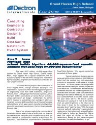
System energy use starts with overcoming the pressurerequired to move air through a heat exchanger (∆ deltapressure). The delta requirement is a product of airflow,coil open area and friction. Net open area does not includethe area used for coil fins, refrigerant tubing, and the allimportantsurface build-up of contaminant and mold.This build-up decreases the open area which will increasecoil pressure drop, decrease air-flow, and increase energy use(Figure A). If CFM were to remain the same, a proportionalincrease in velocity would occur (Figure B). This higherinterstitial velocity decreases the air-to-surface contact time,which decreases heat transfer and would raise the leaving airtemperature. This latent differential of temperature—whichis now lower than when clean—combined with reductionin airflow, will increase space temperature and humidity(wet bulb), decreasing the comfort level of buildingoccupants to where system alterations must be performed.Other coil changes include an increase in air friction,insulating effects, and a continual degradation of coiland drain pan surfaces.A high <strong>UV</strong>-C energy reflection can be obtained from allgrades of aluminum—a phenomena that accentuates <strong>UV</strong>-C’sability to degrade and rid a coil’s surface of contamination(Figure C). There are few organic materials that can escapethe destructiveness of <strong>UV</strong>-C energy.By looking at a fluorescent lamp (Figure D), you can notethe high amount of energy glowing from the lamp’s surface,flooding the air and surfaces with direct and reflected rays.This pales in comparison to Xtreme’s invisible waveform,which is more than 2.5 times that amount.Xtreme outperforms all other products in airborne kill,coil cleanliness and sustained system capacity. It also excelsat affordability, ease of installation, warranties and total costof ownership. Xtreme has become number one everywhere.500 fpmApproach500 fpmApproachFigure A. Pre-cleaned coil shown cut in halfto reveal that it’s not actually clean! Instead,the material compacts deeper into it, furtherreducing air flow and heat transfer. Thepenetrating power of <strong>UV</strong> will actually cleanall surfaces to restore heat transfer to as newas possible.850 fpm Interstitial1000 fpm Interstitial60%Open51%OpenFigure B. A traditional approach velocity of 500 fpm is maintained toshow the change in interstitial velocity when open area is decreased by9% from surface contanimnants like mold. With the increase in velocityand thermal insulation, sensible and latent heat transfer is dramaticallyreduced and space conditions are compromised.Figure C. Illustration of <strong>UV</strong>-C spectral lines reflecting off aluminumat angles associated with the entrance angle. At a minimum, aluminumprovides a varied, unpredictable and dense fog of reflected radiationthroughout. Coil surfaces yield “incident” angle reflection patterns from<strong>UV</strong>-C’s 1/4 micron (0.25) wavelength—a key to <strong>UV</strong>-C’s ability to continuouslyvoid a coil of all collected and agglomerated bio-contaminants.Figure D. Illustrates only a fraction of <strong>UV</strong>-C flux density and shows thebenefit of 360° irradiation (RLM Xtreme). Filling the cavity plus bathingthe coil proves the potential of significantly improved airborne kill ratios.The benefits are obvious when compared to the absorption of photonsby fixtures and reflectors, which decreases the potential for the deathof airborne infectious agents. 360° irradiation is the obvious choice.
About <strong>UV</strong> ResourcesLM Xtreme<strong>UV</strong>R founders fathered <strong>UV</strong>-C energy’s modern applicationin HVACR equipment from patent writing toorientation/application suitability and correctness. Theteam was also primarily involved in ASHRAE’s effort toproduce its first <strong>UV</strong>-C Chapter in the 2008 Systems andEquipment Handbook. Team members were among thefirst to develop modern sizing and efficacy software formost any air conveyance system and have helped differingOEM’s develop their own; as well as new and unique <strong>UV</strong>products for specific applications! The team sits on otherCommittees and also Lectures for ASHRAE on <strong>UV</strong>-C*.They consult with, and are involved in government orgovernment sponsored <strong>UV</strong> related entities.*ASHRAE’s Distinguished Lecturer’s programCorporate OfficeP.O. Box 800370Santa Clarita, CA 91380-0370Phone 877.<strong>UV</strong>4.HVAC (884-4822)Fax 661.296.4856Website www.<strong>UV</strong>Resources.comREPRESENTED BY:Work up a job today atwww.<strong>UV</strong>Resources.comSpecifications subject to change without notice.© <strong>UV</strong> Resources 2005–2009 55000520 Rev B 7/09
RLM XtremeInstallation, Operation ManualP.O. Box 800370 • Santa Clarita • CA • 91380(877) <strong>UV</strong>4-HVAC (884-4822) • Fax: (661) 296-4856www.<strong>UV</strong>Resources.comSpecifications subject to change without notice - ©2005-2008, all rights reserved.
GENERAL INSTALLATION INSTRUCTIONSRLM XtremeCAUTION! Never Expose Eyes or Skin to <strong>UV</strong>-C - Read all Materials before StartingSAFETY CONSIDERATIONSImproper installation, adjustment, alteration, service, maintenance, or use can cause fire, electrical shock, or otherconditions which may cause personal injury or property damage. Consult a qualified installer, service agency, oryour supplier for information or assistance. The qualified installer or agency must use factory kits or accessorieswhen installing this product. Refer to the individual instructions packaged with kits or accessories when installingthem. Follow all safety codes, wear safety glasses and work gloves. Read all instructions thoroughly and followany warnings or cautions attached to any accessed area. Consult local building codes and the National ElectricalCode (NEC) for all applicable requirements.Understand the signal words DANGER, WARNING or CAUTION. These words are universally used for overallsafety. DANGER identifies the most serious hazards, which will result in severe personal injury or death.WARNING signifies hazards, which could result in personal injury or death. CAUTION is used to identify unsafepractices, which would result in minor personal injury or product and property damage.WARNING:General:Before installing or servicing this unit, turn off all power, there may be more than one (1) switch.1. RLM Xtreme fixtures can be used to bathe surfaces, the air or both with <strong>UV</strong>-C energy. For surfaces locatethe RLM Xtreme at known growth areas such as the coil and drain pan first, then other moist areas aroundhumidifiers, etc. They can also be placed in return, supply and mixed air plenums or any combination oflocations.2. Check first for power availability and probable service accesses.3. Reflecting <strong>UV</strong>-C energy within a target cavity increases its fluence and overall effectiveness. Therefore, wherepossible cover all likely reflection sites with <strong>UV</strong>-C reflective materials (e.g. aluminum tape) to reduce anyshadowing and to increase the flux density of <strong>UV</strong>-C energy.Installation:1. Consult all applicable codes before installing. Check fixture label(s) for the correct power requirements andsupply the correct voltage from a suitable, protected (fused or breaker), and grounded power source.CAUTION: Using other than labeled voltages will void product warranty and may do additional damageto the entire system. Fixtures should be operated continuously to avoid growth of mold and bacteria underoptimum conditions (AHU off).2. Power must also be switched at all install access points with a properly rated, SPST interlock switch tocompletely de-energize the assembly when its install location is accessed. Accesses are to have signs inappropriate languages alerting maintenance personnel to the possible hazard of looking at, or exposing skin to<strong>UV</strong>C energy (English label (s) provided). Any access may be equipped with a glass or Lexan® view port toview the lamps. Common glass or Lexan ® will block (absorb) <strong>UV</strong>-C energy.3. <strong>UV</strong>-C energy may damage other plastics. Protect suspect items with known <strong>UV</strong>-C resistant materials (e.g.aluminum tape) when they are in “line of sight” of <strong>UV</strong>-C energy.4. Determine the most desirable <strong>UV</strong>-C lamp location for the intended use and then its power supply. Note: thepower supply may be mounted inside or outside of the target cavity.Mounting1. Use the spacing table below to determine the ideal distancebetween metal lamp clamps (supplied)- Alternative clamps includingSingle and Dual LampHolsters or MagnaClamp can be usedLampClamp(<strong>Inc</strong>luded)Dual LampHolster(Optional)(ordered separately). Mount using the provided self-drilling screws. Lamp clamps may be mounted to anysurface that addresses the intended site. Note: Non-invasive magnetic lampclamps(MagnaClamp) are available, and may be more convenient for theintended install.Page 2MagnaClamp(Optional)55000028 Rev I 7/09
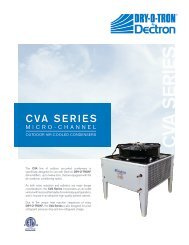
Safety Note: Metal Lamp clamps should not be attached to the “glass” portion of the lamp. LampHolster &MagnaClamps can be arranged to hold lamp at any point on the lamp surfaceLamp Spacing TableNominal Lamp Length Distance between Lamp clamps33” (long) RLM <strong>UV</strong>C Lamp Approximately 31.5”61” (long) RLM <strong>UV</strong>C Lamp Approximately 59.5”Distance between LampClampsMounting Power Supplies using <strong>UV</strong> Resources’ X-Box 2, 4 or 8Note: RLM Xtreme power supplies can be mounted in existing control panels, etc. The X-Box series is used tohouse RLM Xtreme power supplies. These housings provide proper mounting and wiring accommodations foreither 2, 4 or 8 (each) power supplies. They include pre-installed power supply mounting studs, pre-punched basemounting holes, terminal block and wire raceways for power-in and lamp power.When choosing a mounting site, make sure that it can be supplied with the necessary power requirements, ballasthookup, and subsequent physical access for any future service.BCARLM Xbox 2 RLM Xbox 4 RML Xbox 8Dim A 10.75” 17” 17”Dim B 12.25” 11” 22”Dim C 1.75” 1.75” 1.75”Page 355000028 Rev I 7/09
(Shown below is the RLM X-Box -2 mounting plate with the cover removed)Follow these steps1. Secure Power Supply tomounting plate with suppliednuts2. Select location for X-Box(Keep in mind loom length)3. Using 4 self-tapping #8screws (provided) securemounting plate to desiredlocation.4. Locate and route the RLMLampLooms to the X-Boxand mark for cutting Loom tolength.5. After stripping the loomsheath and wire insulation,plug the wires into the powersupplies following the colorcoding diagram on eachpower supply.6. Wire power supplies fromwire block7. Attach source power towire block8. Bring power to X-Box perlocal code (e.g. Liquid-Tight). Note powerrequirements, 120-277Vacothervoltages will voidPower Ratings:The RLM Xtreme products come with 120-277Vac “universal” input at 50/60Hz Power Supplies. Consult localbuilding codes and the National Electrical Code (NEC) for special requirements.CAUTION: Always turn system off, especial power to the power supply before changing lamps. Failure to do somay produce a protection fault within the power supply. Before re-powering a fixture, follow manufacturesinstructions and make sure “all” connections (including lamp pins) are tight and complete to avoid sparks, shorts oroverheating. A protection fault requires a reset procedure. To reset the “programmed start” function of a powersupply, disconnect “all” power and power wires and wait one minute. Start by reconnecting A/C power first and thenturn on all switches. All lamps should light.Connecting Power:1. Read fixture label power requirements – sum the power requirements for all assemblies associated with theinstall and install in accordance National and local codes.2. All power-in wire gauge and switch ratings must be in accordance with applicable codes. Power must also beswitched at all install access points with a properly rated, SPST interlock switch to completely de-energize theassembly when its install location is accessed.3. Apply Door Warning Labels on all access doors/ports/panels as indicated above.RLM Xtreme LampLoomRLM Xtreme LampLoom allows for the remote location of power supplies from the <strong>UV</strong>-C lamp area.Looms are 18 AWG triple-sheathed wire (color coded: 2 blue, 2 red) jacketed withcarbon impregnated thermoplastic for <strong>UV</strong>-C resistance.1. After lamp and power supply location has been determined, measure distanceLampLoom must span & cut loom to proper length;2. Strip protective jacket 1 ½”;3. Strip each wire (red and blue) 3/8”;4. Wire is now prepared for installation into power supply (see above)20’ LampLoomLampLooms come in the following sizes:55000015 RLM Loom Kit - 5' Plenum Rated Wire with 1 Circline Plug55000011 RLM Loom Kit - 10' Plenum Rated Wire with 1 Circline Plug55000010 RLM Loom Kit - 20' Plenum Rated Wire with 2 Circline Plugs each end ∗∗ Note: 20’ LampLooms come with 4-pin connectors on each end, thereby allowing for re-use of “scrap” pieces or theextra 4-pin connector can be discarded.Page 455000028 Rev I 7/09
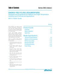
RLM Xtreme Options:PluGL<strong>UV</strong> (P/N: 5500005) provides a <strong>UV</strong>-C resistant, elastic and self-correcting sleeve to ensure water-tightconnections between any single ended lamp and LampLoom socket.1. Slide PluGL<strong>UV</strong> onto lamp 2. Push Plug onto lamp* 3. Roll PluGL<strong>UV</strong> back over connection*IMPORTANT: Lamp to lamp plug connection must be snug to avoid potential arcing.LampLube (P/N: 90001865)1. Apply LampLube liberally to pins 2. Push plug against lamp base firmly**IMPORTANT: Lamp to lamp plug connection must be snug to avoid potential arcingClean all lamps1. Before installation, lamps should be cleaned using 99% isopropyl alcohol and a lint free cloth (<strong>UV</strong>R offers aLamp Cleaning Kit P/N 80000009). Note: If using a <strong>UV</strong> Resources' EncapsuLamp, it is not necessary toclean the surface. Then install lamp by grasping each non-glass end with the thumb and index fingers.Carefully push lamp ends into previously mounted lamp clamps.2. Attach the loom to the lamp by firmly pushing the 4 port connector onto the 4 pins on the lamp end. Note:Connection must be snug to avoid potential arcing.Coil WidthPlenum WidthSide ViewFront ViewRLM Xtreme AHU Installation DrawingPage 555000028 Rev I 7/09
Model NumberPartNumberRLM AccessoriesDescriptionRLM-PG-T5 55000005 PluGL<strong>UV</strong> Watertight lamp connection for all RLM products<strong>UV</strong>R-LL 900001865 LampLube - for lamp to tombstone, or lamp to plug protectionRLM-SLH 55000002 Single LampHolsterRLM-DLH 55000003 Dual LampHolsterRLM-ML 55000124 RLM Xtreme MagnaClamp AccessoryRLM-5-LOOM-KIT 55000015 RLM Loom Kit - 5' Plenum Rated Wire with 1 Circline PlugRLM-10-LOOM-KIT 55000011 RLM Loom Kit - 10' Plenum Rated Wire with 1 Circline PlugRLM-20-LOOM-KIT 55000010 RLM Loom Kit - 20' Plenum Rated Wire with 2 Circline Plugs each endRLM-X-Box-2 55000062 RLM-X-Box-2 Accommodates up to 2 RLM Xtreme 120/277V Power SuppliesRLM-X-Box-4 55000064 RLM-X-Box-4, Accommodates up to 4 RLM Xtreme 120/277V Power SuppliesRLM-X-Box-8 55000068 RLM-X-Box-8, Accommodates up to 8 RLM Xtreme120/277V Power SuppliesREPLACEMENT LAMPSSEL-33-HO-EL-T5-4 55066554 SEL 33" Single Ended- High Output EncapsuLamp (4 pack)SEL-33-HO-EL-T5-32 55066555 SEL 33" Single Ended- High Output EncapsuLamp (32 pack)SEL-61-HO-EL-T5-4 55086554 SEL 61" Single Ended- High Output EncapsuLamp (4 pack)SEL-61-HO-EL-T5-32 55086555 SEL 61" Single Ended- High Output EncapsuLamp (32 pack)EQUIPMENT WARRANTY<strong>UV</strong> Resources (<strong>UV</strong>R) warrants to the original buyer that its Products shall be free from defects in material orworkmanship under normal use and service for the periods of time set forth below. This warranty is contingentupon proper use of Products and will not apply if adjustment, repair or parts replacement is required because of anaccident, unusual physical, electrical or electro-mechanical stress, neglect, misuse, failure of electric power,humidity control, transportation, unauthorized repair actions, or not installed or maintained in accordance with<strong>UV</strong>Rs’ specifications hereunder, or where Product serial numbers have been altered, defaced, or removed. <strong>UV</strong>Rs’obligation under this warranty shall not arise until the Purchaser of the Product returns the defective part to <strong>UV</strong>R.This warranty is limited to the repair and/or replacement of parts. This warranty does not cover any labor orsubsequent damage incurred as the result of Product failure or indirectly arising from the design, construction,installation, servicing, or operation of Products. <strong>UV</strong>R and its resellers’ liability under this warranty shall in no eventexceed the cost of goods sold under the original sale contract.Under the conditions specified above, <strong>UV</strong>R warrants all RLM power supplies for a period of three (5) years fromdate of purchase and all lamps for a period of 12 months from date of installation provided lamps are installedwithin 3 months from date of purchase. Buyer must provide proof of purchase. This is <strong>UV</strong>Rs’ sole warranty. Nowarranties are extended beyond those described herein and it is expressly agreed that this warranty will be in lieuof all warranties of fitness and merchantability. <strong>UV</strong>R neither assumes, nor authorizes any person to assume for it,any obligation in connection with the Products. Buyer shall not return to <strong>UV</strong>R any allegedly defective goods without<strong>UV</strong>Rs’ prior written authorization. This warranty may not be assigned or transferred.<strong>UV</strong> ResourcesP.O. Box 800370 • Santa Clarita • CA • 91380(877) <strong>UV</strong>4-HVAC (884-4822) • Fax: (661) 296-4856www.<strong>UV</strong>Resources.comSpecifications subject to change without notice - ©2005-2009, all rights reserved.Page 655000028 Rev I 7/09