BDF Clocks + chronometers - Amplicon
BDF Clocks + chronometers - Amplicon
BDF Clocks + chronometers - Amplicon

Create successful ePaper yourself
Turn your PDF publications into a flip-book with our unique Google optimized e-Paper software.
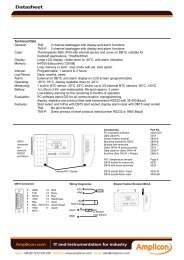
DatasheetUser’s Manual - Instruments <strong>BDF</strong>-xx-TCx8.- CONNECTIONS AND WORKING WITH THE CONTROL LINES___________________________________The <strong>BDF</strong> instruments working as Real Time <strong>Clocks</strong>,can be set on time by closing mechanical contactsbetween terminals 14,13 and 6 of the «Control Terminal»and «GND». Each contact closed will add «+1»on the hours and minutes and will set seconds to zero.Terminal 14 to «GND» .- Adds «HOUR»Terminal 6 to «GND» .- Adds«MINUTE»Terminal 13 to «GND» .- Resets «SECOND»Control Terminal9 +15 Vdc10 STOP11 RESET12 GND13 SECOND14 HOUR15 GND915181 +15 Vdc2 +15 Vdc3 START4 GND5 GND6 MINUTE7 GND8 Not ConnectedNote.- The controls for «HOUR», «MINUTE» and«SECOND» are activated by mechanical contactsclosed to «GND». Internally, the terminals areconnected to +15Vdc through a Pull-Up 4K7 resistor.STOP (pin10)START (pin 3)RESET (pin11)GNDThe <strong>BDF</strong> instruments working as Chronometers withup or down function have 3 controls for «START»,«STOP» and «RESET». By default, these functionsare activated by «Down-Edge» with a mechanicalcontact to «GND». Intenally, the terminals areconnected to +15Vdc through a Pull-Up 4K7 resistor.Terminal 11 to «GND».- «RESET»Terminal 3 to «GND».- «START»Terminal 10 to «GND».- «STOP»Note .- Each control line can be configured independentlyto be activated by «Down-Edge» or «Rising-Edge». Toconfigure to «Down-Edge» use jumpers JP6, JP7, JP8and place the polarization resistors ad «Pull-Down»(Jumpers JP5, JP9, JP10). Note that in this case, thesignals will be activated with a mechanical contactconnected to «+15 Vdc» (allowable at the same «ControlTerminal») (See section 11 for jumpers position)9.-CONNECTIONS FOR ALARM AND ACTIVATING THE «PRESET»_________________________________ALARMChronometer units have an «ALARM» function whichactivates when the display reaches «00:00:00» onDown-Chronometers, or when the display reaches the«PRESET» value on Up-Chronometers. When the«ALARM» activates, the following procedure occurs :AlarmConnectionsA Alarm +B Not ConnectedC Not ConnectedD Alarm -STOPFLASHSIGNALtime counting stopsdisplay flashesthe transistor output gets activeWhen pressing «RESET» the unit will reset thedisplay to «00:00:00» or to the «PRESET» value.Note .- The «ALARM» function can be disabled byacting on internal jumpers (see section 11).PRESETChronometer units have a «PRESET» value that canbe configured to a predefined display time.Down-Chronometer units will load the «PRESET»value on display when pressing a «RESET», and willcount down from the «PRESET» value when «START»is pressed.Up-Chronometer units will activate «ALARM» whenreaching the «PRESET» value.CONFIGURING THE «PRESET» VALUEStop the counting of the chronometer («STOP»). Press«SECOND» (pin13) and the «PRESET» value will appearon display.Note .- Only the 4 most significant digits of the«PRESET» can be modified. Instruments with«HH:MM:SS» format can modifiy the HH and MM values.Units with «HH:MM» and «MM:SS» formats can modify all4 digits.Mantaining «SECOND» pressed, press «HOUR» or«MINUTE» to increase the value of the «PRESET». Thedefault value for the «PRESET» is «01:01:00» (or «01:01»for units with 4 digits).Note .- Pressing «Hour» and «Minute» simultaneously willset the «PRESET» value to «00:00:00»FEMA ELECTRÓNICA - Page 6<strong>Amplicon</strong>.comIT and Instrumentation for industrySales: +44 (0) 1273 570 220 Website: www.amplicon.com Email: sales@amplicon.com
DatasheetUser’s Manual - Instruments <strong>BDF</strong>-xx-TCx10.- OUTPUT RS422 - TIME SYNCHRONIZATION_________________________________________________All <strong>BDF</strong> Clock units with «MASTER» function (RealTime <strong>Clocks</strong> and Chronometers) have a RS422 ASCIIoutput connection to send data to «SLAVE» units. All«SLAVE» units receive this data and show on displaythe same time as the «MASTER» time, being bothunits time synchronized.Conection between «MASTER» and «SLAVE» isdirect, connecting pins «A» to «A» and «B» to «B». Noadditional configuration is needed.SLAVE1SLAVE2MASTERConnections RS422SLAVE31569Pin1.- APin2.- BPin5.- GNDTwisted and shielded cable. Shieldto the «GND» connector of the«MASTER». Do not connect theShield to the «SLAVE» units.SLAVE nDATA FORMAT TRANSMITTED ON THE RS422For applications where the «SLAVE» unit is controlledfrom a «MASTER» which does not belong to the <strong>BDF</strong><strong>Clocks</strong> series (PLC or PC), the information for theHH:MM:SS (or HH:MM or MM:SS) to display must betransmitted to the «SLAVE» in the folowing format:maximum 32 unitslast instrument must haveterminator jumper connected (JP1closed)Model TC1 and TC4Model TC2 and TC5Model TC3 and TC6MM.SS «CR»HH.MM «CR» andHH «NUL» MM «CR»HH.MM.SS «CR»Note .- in models «HH:MM» two different data typesare sent, in order to activate / deactivate the centralpoints between the HH and the MM. This creates ablinking effect showing that the unit is receiving dataand working correctly.Codes sent correspond to the following HEXcharacters:«H» «30» to «39» HEX (0 to 9 decimal)«M» «30» to «39» HEX (0 to 9 decimal)«S» «30» to «39» HEX (0 to 9 decimal)«.» character «2E» HEX«-» character «2D» HEX«NUL» character «00» HEX«CR» character «0D» HEXFormat1 bit Start8 bits Data No Parity1 bit StopNote .- When «MASTER» unit is not showing a valid timevalue on display (it is being reconfigured or the «ALARM»state is active) the data format sent on the RS422 bus is:-- «NUL» -- «NUL» -- «CR»-- «NUL» -- «CR»-- «NUL» -- «CR»FEMA ELECTRÓNICA - Page 7<strong>Amplicon</strong>.comIT and Instrumentation for industrySales: +44 (0) 1273 570 220 Website: www.amplicon.com Email: sales@amplicon.com
DatasheetUser’s Manual - Instruments <strong>BDF</strong>-xx-TCx11.- JUMPERS CONFIGURATION________________________________________________________JP1JP2JP3JP4JP5JP9JP10JP8JP7JP6IMPORTANT .- To apply the changes made on jumpersand minidips, unplug and plug again the power to theinstrument.minidipsminidipsD1 . . . . . . D12JPA2JPA3 (Open)JPA4 (Open)ON1 2 3 4 5 6 7 8 9 10 11 12OFFJPA1RS422 Bus TerminatorJP1 Closed RS422 with terminator (220 Ohms)Antirrebound Filters for Control SignalsJP2 Closed Antirrebound filter for “STOP” (5 Hz )JP3 Closed Antirrebound filter for “START” (5 Hz)JP4 Closed Antirrebound filter for “RESET” (5 Hz)Configuring the Control SignalsConfiguration for the 1 KOhm polarization resistors forcontrol signals. Depending on the position ofthe jumpers,the polarization resistors will be configured asPull-Up ( ) or Pull-Down ( ).JP5 StopJP9 StartJP10 ResetThe control signals will be activated by “Rising-Edges”( ) or “Down-Edges”( ).JP6JP7JP8StartStopResetAlarm Active on(dip1) Inactive offChronometer Up./Down. Down on(dip2) Up offLuminosity 100% on on(dip3, dip4) 75% on off50% off on25% off offReal Time Clock type HH:MM on(dip5) MM:SS offnote .- for HH:MM:SS select HH:MM and jumper JPA2closedReal Time Clock mode 24 hours on(dip6) 12 hours offOutput RS422Newport mode on(dip7) standard offType of unit Chronometer on(dip8) Clock off(dips9, 10, 11 y 12) not used offBy default, configuration is “activation by “Down-Edges” for all controls, “Pull-Up” resistances andconnections through mechanical contact to “GND”Master or Slave unitsJPA2 Close for “SLAVE” units (TCS)JPA2 Open for “MASTER” units (TC1, TC2, TC3, TC4,TC5 and TC6)Units with 4 or 6 digitsJumper JPA1 ClosedJumper JPA1 Open6 digits4 digitsFEMA ELECTRÓNICA - Page 8<strong>Amplicon</strong>.comIT and Instrumentation for industrySales: +44 (0) 1273 570 220 Website: www.amplicon.com Email: sales@amplicon.com
12345678901234567890123456781234567890123456789012345678123456789012345678901234567812345678901234567890123456781234567890123456789012345678123456789012345678901234567812345678901234567890123456781234567890123456789012345678123456789012345678901234567812345678901234567890123456781234567890123456789012345678123456789012345678901234567812345678901234567890123456781234567890123456789012345678DatasheetUser’s Manual - Instruments <strong>BDF</strong>-xx-TCx12.- SIZES AND DIMENSIONS_________________________________________________________________Size 24/26 A B C4 digits 57mm 264mm 120mm 112mm(2’’) (10,40’’) (4,75’’) (4,41’’)6 digits 57mm 384mm 120mm 112mm(2’’) (15,12’’) (4,75’’) (4,41’’)CBARear Side CoverSize 44/46 A B CAntirreflexive Filter4 digits 100mm 480mm 180mm 112mm(4’’) (18,90’’) (7,09’’) (4,41’’)6 digits 100mm 668mm 180mm 112mm(4’’) (27,10’’) (7,09’’) (4,41’’)Note .- add 27mm to the «C» dimmension for the powersupply plug13.- PANEL CUT-OUT AND WEIGHT___________________________________________________________Size 24/26 D E WeightPANEL CUT-OUT4 digits 57mm 256mm 112mm 2.3 Kg(2’’) (10,07’’) (4,40’’) (5 lbs)6 digits 57mm 376mm 112mm 2.7 Kg(4’’) (14,80’’) (4,40’’) (6 lbs)1234567890123456789012345678D1234567890123456789012345678ESize 44/46 D E WeightPanel widthMax. 14 mm (0,55’’)Min. 2,5mm (0,10’’)4 digits 100mm 472mm 172mm 5.0 Kg(4’’) (18,58’’) (6,77’’) (11,0 lbs)6 digits 100mm 680mm 172mm 5.7 Kg(4’’) (36,77’’) (6,77’’) (12,5 lbs)14- PANEL INSTALLATION _________________________________________________________________Introduce the instrument «1» into the panel cut-outand place a fixation piece «3» on each side. Place thescrew «2» through the fixation piece «3» until itpresses the panel «4» and is firmly fixed.Note .- The front of the instrument is sealed with aprotection level IP65. To have the same level ofprotection between the panel and the instrument,place a rubber profile (squared or round) as indicated«5».«1» Instrument <strong>BDF</strong>«2» Screw«4» Panel «3» Fixation piece«5» Rubber profileFEMA ELECTRÓNICA - Page 10<strong>Amplicon</strong>.comIT and Instrumentation for industrySales: +44 (0) 1273 570 220 Website: www.amplicon.com Email: sales@amplicon.com
DatasheetUser’s Manual - Instruments <strong>BDF</strong>-xx-TCx15.- SECURITY PRESCRIPTIONS___________________________________________________________________INSTALLATION PRECAUTIONS.- The installationand operation of this instrument must be done byqualified operators. This instrument DOES NOT havepower switch and will start to operate as soon asthe power supply is connected. The instrument has an internalprotection fuse, according to IEC-127/2, and is located inside thepower-supply connector. The values areFuse 200 mA Time Lag (for 230 Vac power)Fuse 400 mA Time Lag (for 115 Vac power)Fuse 350 mA Fast (for 24 Vdc power)When the instrument is used to control machines or processes wherethe personnel or the process can be damaged, the appropriate securityelements must be added to the system in order to protect the operatorand / or the system.SAFETY PRESCRIPTIONS.- This instrument has beendesigned and verified according to the UNE-20553 rules andis delivered in perfect conditions of operation. This manual contains theadequate information for the electrical installation. Before startingoperations for connections, readjustment, substitution, maintenance,repair, etc, the instrument must be unplugged from the power supply.The instrument must be installed in places with good ventilation to avoidexcesive heating, and far from sources of electrical noise or magneticfield generators, such as power relays, electrical motors, speedcontrols, etc... The instrument can not be installed in open places. Donot use until the installation is finished. The instrument is designed tobe mounted on a metallic panel with the adequate protections. DO NOTclean the front lens with abrasive products (such as solvents, alcohol,etc) use a clean and water humid rag. Do not expose the instrumentto excesive moisture. DO NOT operate the unit in the pressence offlammable gases or fumes.EXCITATION VOLTAGE Vexc.-Instruments <strong>BDF</strong>-xx-32 and <strong>BDF</strong>-xx-36 supply an excitation voltage of10 to 24 Vdc (50mA) to power transducers, available betweenterminals A and C. Do NOT connect these terminals to an externalpower supply, permanent damages may result on both instruments.POWER SUPPLY .- Connect the Power Supply to the terminalsindicated in this manual. Verify that the voltage and frecuency of thepower supply is according to the voltage and frecuency valuesindicated in the label attached to the unit. DO NOT connect theinstrument to power lines which are overloaded, or power lines withloads working in ON/OFF cycles, or with inductiveloads.SIGNAL WIRING .- Information to considerrelating the wiring of the sensors, probes,transducers, etc. The wires can act as antennas and introduceelectrical noise from the environment into the signal wires, speciallyif the wires are close to noise sources or electromagnetic sources.There are several rules generally known which should be taken intoconsideration for the wiring :a.- DO NOT install impulse, control or signal wires together in thesame conduits as the wires connected to power lines,connected to CC or AC engines, electromagnets, ...b.- When using shielded wires, connect the shield to the commonof the instrument, and leave not-connected the probe sidec.- The wires of impulse, control and signal should be placed inplaces far away from switches, transformers, control relays,etc...IN CASE OF FIRE1.- Disconnect the unit from the power supply.2.- Give the alarm according to the local rules.3.- Switch off all the air conditioning devices.4.- Attack the fire with carbonic snow, do not usewater in any case.WARNING : In closed areas do not use systems with vaporizedliquids.16.- WARRANTY_________________________________________________________________________________FEMA ELECTRÓNICA, S.A. warrants this instrument free of defectsfor a period of 24 MONTHS from the date of shipment. This warrantycovers both the materials of the instrument and the processes usedfor manufacturing.This warranty is excluded and does not apply if the instrument isdamaged due to misuse, improper application, accident, or if theinstrument has been manipulated or repaired by unauthorizedpersonnel or companies.17.- DECLARATION OF CONFORMITY______________________________________________________________DECLARATION OF CONFORMITYManufacturer.- FEMA ELECTRÓNICA, S.A.Address.- Pol. Ind. Santiga - Altimira 14 (T14 - N2)E-08210 Barberà - BARCELONAESPAÑA - SPAINDIRECTIVESEUROPEAN DIRECTIVE FOR LOW VOLTAGE D73/23/CEE AMMENDED BYD93/68/CEE. Equipments powered from 50 to 1000 Vac and/or from 75 to 1500 Vdc.Conforming ProductsSeries.- <strong>BDF</strong>-24, <strong>BDF</strong>-26, <strong>BDF</strong>-44 and <strong>BDF</strong>-46Models.- TC1, TC2, TC3, TC4, TC5, TC6, TCSEUROPEAN DIRECTIVE FOR ELECTROMAGNETIC COMPATIBILITY D89/336/CEE AMMENDED BY D93/68/CEESTANDARDSWe hereby declare that the above products conform to theessential protection requirements of Directives and IMMUNITY UNE EN 50082-1 (1998)Harmonized standards indicated below.EMMISIONSELECTRICAL SAFETYUNE EN 50081-2 (1994)UNE EN 61010-1 (1997)Signed.- D. JuncàUNE EN 60204-1 (1998)Position.- Quality ManagerNOTE .- During an electromagnetic disturbance (10V/m) it is permitted a worst case error of 1% of the A/D range.Place .- Barberà, 2005The instrument will recover automatically its functionality when the disturbance stops, without need of the operatorto reset or restart.FEMA ELECTRÓNICA - Page 11<strong>Amplicon</strong>.comIT and Instrumentation for industrySales: +44 (0) 1273 570 220 Website: www.amplicon.com Email: sales@amplicon.com