
Create successful ePaper yourself
Turn your PDF publications into a flip-book with our unique Google optimized e-Paper software.
<strong>PC237</strong>Appendices Contents follow…APPENDICESAPPENDIX SUBJECT PageAPPENDIX ATECHNICAL SPECIFICATION1 Hardware A - I2 Software A - III3 Environmental Conditions A - V4 Optional Accessories A - VAPPENDIX BGLOSSARY OF TERMSAn explanation of some terms used in this manual and data acquisition applicationsB - IAPPENDIX CCIRCUIT and LAYOUT DIAGRAMSContents of Appendix C1 Circuit Schematic sheet 1 - PC Interface2 Circuit Schematic sheet 2 - Digital Output Opto-Isolators3 Circuit Schematic sheet 3 - Digital Input Signal receivers4 Circuit Schematic sheet 4 - Digital Output DriversC - I5 <strong>PC237</strong> Board Layout Assembly DetailsNOTESC - IICONTENTS - 4
<strong>PC237</strong><strong>PC237</strong> OPTO-ISOLATED DIGITAL INPUT/OUTPUT BOARD1. INTRODUCTION1.1 The <strong>Amplicon</strong> 200 SeriesThe <strong>Amplicon</strong> 200 Series of Personal Computer based data acquisition products providesvery high performance, affordable hardware with user sympathetic software. The 200 Seriesis designed for users requiring fast or complex data input/output to the host PC and comprisesa range boards and software to handle most analog and digital signal types. When a largescale system is required, multiple boards can be added from the 200 Series without conflictand the capacity of the PC mounted hardware can be extended by external expansion panelsto provide a convenient to use system with low cost per channel and maintained highperformance.1.2 Features of the <strong>PC237</strong>The <strong>PC237</strong> is a full featured opto-isolated digital input/output board which will meet the moststringent requirements.• Fits any 286, 386 or 486 AT compatible computer• Part of 200 Series expansible system• Opto isolation between inputs, outputs and system ground up to 2 kV ac• Very high noise immunity• Wide range of input and output levels• 16 bit input word with 2 byte split isolation• 16 bit output word with 2 byte split levels• Active true logic input and output• Fail-to-low output lines• Multiple boards supported in a single PC• Two isolated external interrupt control lines• Multiple operating modes• Programmed or external control• Two selectable IRQs on eight possible levels for interrupt controlled input/output• Flexible card base address in the range 000 to FFC 16• DART200 applications software package included• DASH200 digital I/O software included, running under Microsoft Windows 3• DOS library routines in QuickBASIC, Turbo Pascal, Microsoft and Borland C/C++• Windows Dynamic Link Library (DLL) optionally available with Visual Basic examples• Set of <strong>PC237</strong> Labtech Notebook drivers included• Supported by PowerLab Software Development EnvironmentINTRODUCTION Page - 1
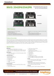
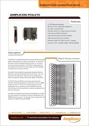
<strong>PC237</strong>1.3 General DescriptionThis section 3.1 provides an overview of the functions of the hardware and software providedwith the <strong>PC237</strong> package.1.3.1 The HardwareThe <strong>PC237</strong> is a full length plug-in board which provides 16 bits of digital input with split (2 x 8bits) isolation, 16 bits of isolated digital output and two isolated external control lines. Theboard can be used on any 286, 386 or 486 computer with an IBM compatible ISA (AT) bus.The block schematic of the <strong>PC237</strong> illustrates the important elements of the board and isshown in figure 1.1. The architecture comprises several major sub-systems briefly describedbelow, with more details of connections and usage provided in later sections.I/P Bit 0I/P Bit 1I/P Bit 2I/P Bit 3I/P Bit 4I/P Bit 5I/P Bit 6I/P Bit 7Ext Common AI/P Connector AInputOpto-IsolatorsBits 0-716 bit DataInput BufferBaseAddressSelection16 bitDataBusPCInterfaceDataBuffers16 bitDataI/OI/P Bit 8I/P Bit 9I/P Bit 10I/P Bit 11I/P Bit 12I/P Bit 13I/P Bit 14I/P Bit 15Data AvailableExt Common BI/P Connector BO/P Connector CInputOpto-IsolatorsBits 8-15andControlControl & AddressLogicInterruptMaskRegister2PCInterfaceControl &AddressBuffersIRQ LevelSelectionJumpers12 bitAddressControlI/O8IRQsData RequestExt VoltageO/P Bit 0O/P Bit 1O/P Bit 2O/P Bit 3O/P Bit 4O/P Bit 5O/P Bit 6O/P Bit 7O/P Bit 8O/P Bit 9O/P Bit 10O/P Bit 11O/P Bit 12O/P Bit 13O/P Bit 14O/P Bit 15Ext Common COutputDriversBits 0-7OutputDriversBits 8-15Opto- IsolatorOutputOpto-IsolatorsBits 0-1516 bitDataOutputRegisterINTERFACETO HOST PCIsolationBarriers+5VFIGURE 1.1<strong>PC237</strong> BLOCK SCHEMATICPage - 2INTRODUCTION
<strong>PC237</strong>1.3.1.1 Isolated Digital Input Sub-systemThe isolated digital input sub-system accepts a 16 bit digital data word from an externalcomputer incompatible source and conditions the voltage levels of this word for input to thehost PC. The input circuits accept a wide range of signal voltages and the common modevoltage (between source and the PC chassis) can be as high as 2 kV ac. For flexibility ofconnection to different sources, the 16 bit input word is split into two 8 bit bytes, each isolatedfrom the other and from system ground. When connected to two separate 8 bit sources, the16 bits are still read as a single word.A 'Data Available' control bit informs the PC that a data word is ready for input from thesource. This bit is electrically referred to the high byte isolation level. The PC reads the dataword that is present on its input connectors at the time that the READ instruction is carried outand does not store this value in the <strong>PC237</strong>.1.3.1.2 Isolated Digital Output Sub-systemThe isolated digital output sub-system provides a 16 bit digital data word from the host PCand converts these bits to drive an external computer incompatible load. The output circuitsoperate over a wide range of load conditions and the common mode voltage (between sourceand the PC chassis) can be as high as 2 kV ac. For flexibility of connection to different loads,the 16 bit output word is split into two 8 bit bytes, each byte being supplied from its ownvoltage source (Vs) and therefore capable of output drives at two different levels. Whenconnected to two separate 8 bit loads, the 16 bits are still sent as a single word.A 'Data Request' control bit informs the PC that a data word is required by the load. Theoutput is held in a 16 bit register on the <strong>PC237</strong> and is not changed until a new word is outputor the register is reset.1.3.1.3 InterruptsBoth 'Data Available' and 'Data Request' signals generate separate Interrupt Request (IRQ)signals to the computer when either one is activated. The IRQ levels at which these interruptsare generated are previously set by jumpers on the <strong>PC237</strong>, and each can be individuallymasked by software using two bits in the control word.1.3.1.4 ControlOn board control signals are generated by logic implemented in GALs. All timing of operationsis under the control of signals from the PC I/O bus.1.3.1.5 The PC InterfaceCommunication between the host PC and the <strong>PC237</strong> digital I/O board is via the PC interfacebus. The bus provides data, address, interrupt and control lines together with power supply forthe <strong>PC237</strong>.The <strong>PC237</strong> occupies four address locations in the available I/O space, two contiguous portsfor the 16 bit digital I/O, one for the control/status byte and one reserved. The board baseaddress can be set at any position between 000 and FFB 16 where the least significant digit is0, 4, 8 or C.INTRODUCTION Page - 3
<strong>PC237</strong>The <strong>PC237</strong> uses only the +5 volt supply from the host PC.1.3.2 The SoftwareThe <strong>PC237</strong> is supplied with the software described in paragraphs 1.3.2.1 through 1.3.2.5 aspart of the standard package:1.3.2.1 DART200 for the <strong>PC237</strong> Applications ProgramDART200 is a fully functional program that exercises all major operations of the boardand performs real digital data input and output in all modes.DART200 for the <strong>PC237</strong> provides the following features:• Turbo Vision windowing application• Multiple, resizeable, overlapping full colour windows• Pull-down menus• Mouse support• Dialog boxes• Scroll bars, input boxes, check boxes and radio buttons• Standard handling of keystrokes and mouse clicks• Interrupt controlled, programmed and timed modes of operation• Acquire digital data in all modes• Send digital output data in all modes• Display all acquired digital data in multiple windows• Import data files from other applications• EasyList capability to set up the output list• Save data files for post processing in other applications• Save set-up configuration for later recall1.3.2.2 DASH200 for the <strong>PC237</strong> Windows Application programDASH200 is a Windows 3 applications program that supports the relevant functions of the<strong>PC237</strong> and other 200 Series boards. DASH 200 for the <strong>PC237</strong> provides the followingfeatures:• Acquire and display data from the digital input channel• Control digital outputs• Easy to use menu driven setup and operation• User selectable full colour displays• Save and recall Set up configurations1.3.2.3 DOS Functions LibraryLibrary functions in Microsoft C/C++, Borland C/C++, Borland Turbo Pascal andMicrosoft QuickBASIC. These DOS library functions provide easy access to all of thePage - 4INTRODUCTION
<strong>PC237</strong>programmable features of the <strong>PC237</strong>, provide easy handling of data with data bufferfunctions and simplify the writing of user programs in any of the above languages.1.3.2.4 Programming ExamplesExamples of function usage are given in MicroSoft C, Borland C, Borland TurboPascal and Microsoft QuickBASIC. Microsoft Visual Basic examples are provided withthe Dynamic Link Library.1.3.2.5 LabTech Notebook DriversA set of drivers to use the <strong>PC237</strong> in the Labtech Notebook Data Acquisition andAnalysis software package. Labtech Notebook is available from <strong>Amplicon</strong> LivelineLtd.1.3.3 Optional Dynamic Link Library (DLL)A library of DLL functions provides programmers with a Windows interface to all thefeatures of the <strong>PC237</strong>. The DLL functions can be called by software written in anylanguage that uses the Windows calling conventions, e.g. :MicrosoftC version 6 or aboveVisual CVisual BasicBorland C++ version 3 or aboveTurbo C++Turbo Pascal for Windows1.4 What the <strong>PC237</strong> Package ContainsThe package as delivered from <strong>Amplicon</strong> Liveline Ltd. contains:-1. The <strong>PC237</strong> plug-in card protected by an anti-static plastic envelope.CAUTIONSome of the components on the board are susceptible to damage by electrostatidischarge, and proper handling precautions should be observed. As a minimum, aearthed wrist strap must be worn when handling the <strong>PC237</strong> outside its protective baFull static handling procedures are defined in British Standards Publication BS5753When removed from the bag, inspect the board for any obvious signs of damaand notify <strong>Amplicon</strong> if such damage is apparent. Do not plug a damaged board inthe host computer. Keep the protective bag for possible future use in transportinthe board.INTRODUCTION Page - 5
<strong>PC237</strong>2. The included distribution software on two 3 1 /2 inch high density diskettesApplications Diskette Part Nº 869 356 18Includes DART200 DOS Application ProgramDASH200 Windows Application ProgramREAD.ME Latest InformationTools Diskette Part Nº 869 356 19IncludesDOS Library Functions in four languagesExamples in four languagesLabTech Notebook DriversREAD.ME Latest InformationPlease note:Software items are supplied on 3 1 /2" diskettes. Pleaserequest copies on 5 1 /4" diskettes if this size is moreconvenient.3. This <strong>PC237</strong> Instruction Manual Part Nº 859 356 14Any additional accessories (termination boards, cables, optional software etc.) may be packedseparately.1.5 The <strong>Amplicon</strong> Warranty Covering the <strong>PC237</strong>This product is covered by the warranty as detailed in the Terms and Conditions stated in thecurrent domestic or international <strong>Amplicon</strong> Liveline catalogue.Adding options in accordance with the guidelines given in this manual will not void thiswarranty unless any damage is a direct consequence of mishandling.DO NOT MAKE ANY MODIFICATIONS TO A PRODUCT THAT IS ON EVALUATION.Page - 6INTRODUCTION
<strong>PC237</strong>2. GETTING STARTED2.1 General InformationWhen the user is equipped with the <strong>PC237</strong> and a suitable host PC (see paragraph 2.3), fourmethods are provided for starting digital input/output operations:DOS UsersThe <strong>PC237</strong> is supplied complete with DART200 for the <strong>PC237</strong>, a full featured applicationsprogram written in Borland C++ and making use of Turbo Vision and the supported libraryroutines. DART200 runs under DOS and no further software is required to run this applicationprogram.Windows 3 UsersWindows based <strong>Amplicon</strong> DASH200 is supplied with the <strong>PC237</strong>. Microsoft Windows 3 orabove is required to run this application.LABTECH NOTEBOOK UsersDrivers for using the relevant I/O types of the <strong>PC237</strong> under Labtech Notebook are supplied.The LABTECH NOTEBOOK application package is required to use these drivers.Dedicated ApplicationsDOS library routines to support users programs in QuickBASIC, Turbo Pascal, MicrosoftC/C++ and Borland C/C++ are included.An optional library of DLL functions provides a Windows programmers interface to all thefeatures of the <strong>PC237</strong>.Extensive examples of using the functions are given in each supported language.2.2 Installing the CardENSURE THAT THE POWER TO THE COMPUTER IS SWITCHED OFF BEFOREINSTALLING OR REMOVING ANY EXPANSION BOARD. OBSERVE HANDLINGPRECAUTIONS NOTED IN SECTION 1.4. REPAIR OF DAMAGE CAUSED BY MIS-HANDLING IS NOT COVERED UNDER THE AMPLICON WARRANTY.BE AWARE THAT HIGH VOLTAGES MAY EXIST ON THE <strong>PC237</strong> BOARD WHENCONNECTED TO ISOLATED EXTERNAL EQUIPMENT.Please refer to the manufacturer's hardware manual supplied with the PC for instructions onhow to remove the cover and install devices into an input/output slot. The <strong>PC237</strong> may beinstalled in any available position in the machine provided it is a 16 bit full-length slot andthere is no restriction specified for that location by the computer manufacturer.GETTING STARTED Page - 1
<strong>PC237</strong>The <strong>PC237</strong> is factory configured ready to run with the DART200 and DASH200 and if thereare no other devices installed in the computer that are likely to cause conflicts, then for initialfamiliarisation purposes the <strong>PC237</strong> will need no jumper or switch changes.Factory switch and jumper settings are described in sections 2.7 and 2.8. The factory defaultsprovide the following configuration:Base Address 300 16Interrupt Levels Data Available - IRQ AData Request - IRQ BRefer to the relevant section if changes need to be made to any setting before installing the<strong>PC237</strong> in the computer.2.3` Host Computer RequirementsWhen installing a <strong>PC237</strong> Isolated Digital I/O Board, ensure that the host computer hassufficient capacity. Take into account other boards or adapters that may be installed in thecomputer when assessing physical space, address space in the I/O map, interrupt levels andthe power requirements. A suitable host computer configuration is:IBM©or fully compatible PC/AT with 286, 386 or 486 processor, 3 1 /2" high densityfloppy disk drive and monitor. A hard disk drive and colour monitor aredesirableOne free full length I/O card slot with AT bus connectors for the <strong>PC237</strong>Sufficient power available. +5 volts at 0.4 amps.DOS 3 or higherMicrosoft WINDOWS 3 or higher to run DASH2002.4 Backing up the Software DiskettesIt is important that backup copies of the software diskettes are made and the originals storedin a cool, dry, safe place. Each diskette can be copied onto a blank diskette and/or thesoftware copied onto the hard disk.Always use the working copies.2.5 Loading the DART200 ProgramFor demonstrations and many real digital data I/O applications, DART200, properlyconfigured, will provide all the functionality that is required. The program is easy to use andprovides a quick introduction to the facilities of the <strong>PC237</strong>. It also provides a quick and easymeans of testing the board and its connections if a problem is later suspected.In order to load the program you must:1. Boot up the system2. Log on to the drive containing the DART200 for the <strong>PC237</strong> filePage - 2GETTING STARTED
<strong>PC237</strong>3. Type DART200The program will load and a menu driven screen will be presented with a central informationbox describing the program version.2.6 Running the DART200 ProgramPress Function Key F1 or click on 'Help' in the Status Line at any time for on line helpand note the hints in the status line.If a mouse is installed, click on OK in the information box, otherwise pressreturnClick on SETUP in the top menu bar or press Alt-S if a mouse is not installedView the items in the Setup menu by selecting with the mouse or indicatedkeysBoard DetailsEnsure that the board details are correctBoard base Address in the software is set to the same value as seton the <strong>PC237</strong> DIL switch SW1. Default setting is 300 16Interrupt Levels are the same as those set up by jumpers on theboard. Default levels are Data Available on IRQ A and Data Requeston IRQ B.Click on the 'Register' box to enable the programSet up the other parameters as required.Click on GO in the bottom status bar or press F9 to startREMEMBER – Press Function Key F1 or click on 'Help' in the StatusLine at any time for on-line, context sensitive help.Help hints are also given on the status line whenever a menu selectionis being made.For maximum effectiveness when used for demonstration purposes, the DART200application program requires real signals on the input, and a representation of thesesignals is displayed on the screen. Refer to section 3 for information on connection ofthe input signals.2.7 Customer-configured Base AddressThe base address of the <strong>PC237</strong> can be selected in the range 000 to FFC 16 , where the leastsignificant digit must be 0, 4, 8 or C. It is the users responsibility to ensure that a baseaddress is chosen for the <strong>PC237</strong> that is in the allowable range of the PC in use and does notconflict with any registers used internally or on other expansion boards.GETTING STARTED Page - 3
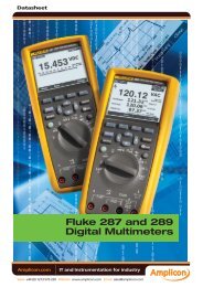
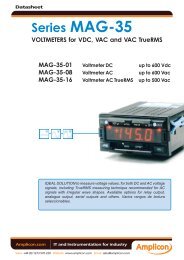
<strong>PC237</strong>Base address configuration is accomplished by selecting the appropriate settings of SW1, adual-in-line bank comprising ten single-pole switches. The most significant hex digit is codedby the four switches SW1-1 to SW1-4 and the next hex digit by SW1-5 to SW1-8. The leastsignificant digit is set up by SW-9 and SW-10.In figure 2.1 below, the left hand illustration shows base address 300 16 selected. SW1-3 and 4are switched to '1' (switch on) and SW1-1, 2, 5, 6, 7 and 8 are switched to '0' (switch off). Thissetting is the factory default configuration, and the <strong>PC237</strong> occupies an area designated forprototype cards in the PC I/O map. The right hand illustration shows an example of baseaddress 1C8 selected.SW1SW1ONON1 2 3 4 5 6 7 8 9 101 2 3 4 5 6 7 8 9 10800400200100 80 40 20 10MS8 4LS800400200100 80 40 20 10MS8 4LSThis example shows the defaultBase Address 300 selectedThis example shows theBase Address 1C8 selectedFIGURE 2.1.TWO EXAMPLES OF BASE ADDRESS DIL SWITCH SELECTION2.7.1 PC I/O MapThe standard PC/AT I/O map assignments are listed below.I/O addresses 000 to 0FF 16 are reserved for the PC system board I/O. 100 to 3FF 16 areavailable on the I/O channel.Hex RangeUsage1F0-1FFHard Disc (AT)200-20F Game/Control210-21F Reserved238-23B Bus Mouse23C-23FAlt. Bus Mouse270-27F Parallel Printer2B0-2DFEGA2E0-2E7GPIB (AT)2E8-2EFSerial Port COM42F8-2FFSerial Port COM2300-31F Prototype Card360-36F Network378-37F Parallel Printer380-38F SDLC3A0-3AFSDLC3B0-3BBMDA3BC-3BFParallel Printer3C0-3CFEGAPage - 4GETTING STARTED
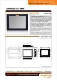
<strong>PC237</strong>3D0-3DF3E8-3EF3F0-3F73F8-3FFCGASerial Port COM3Floppy DiscSerial Port COM1The installation of the <strong>PC237</strong> at a base address that uses unlisted ports may result inconflicting assignments with third party adapters.2.8 Selection of Interrupt Request (IRQ) LevelsSelection of the required Interrupt Request Levels is by means of two jumpers in separatepositions on header J1 - 4. Eight levels are available, but only two of these may be selected,and levels should be chosen that do not conflict with any other assignments within the hostcomputer. The interrupts can also be enabled or disabled by software and this requires writingto the Control Register.The factory default setting is Data Available on IRQ level A (IRQ10) and Data Request on IRQlevel B (IRQ11).The two out of eight position jumper is illustrated in figure 2.2. which shows the 'DataAvailable' interrupt patched to IRQ default level A and the 'Data Request' interrupt on IRQdefault level B.Interrupt Jumper PadData RequestData AvailableF C B A 9 7 5 3IRQ LEVELFIGURE 2.2.JUMPER FOR IRQ LEVEL SELECTIONThe table below shows the available levels on the <strong>PC237</strong> and normal usage of all hardwareinterrupts.<strong>PC237</strong> Host PC Host PC Host PCJ1 - 4 IRQ Interrupt DescriptionIRQ LEVEL Name Number of Usage— 0 8 16 Timer ) Not available on the— 1 9 16 Keyboard ) Bus Connectors— IRQ2 A 16 Int 8 - 153 IRQ3 B 16 COM or SDLC— IRQ4 C 16 COM or SDLC5 IRQ5 D 16 LPT— IRQ6 E 16 Floppy Disk7 IRQ7 F 16 LPT— IRQ8 70 16 Real Time Clock9 IRQ9 71 16 Re-directed to IRQ2A IRQ10 72 16 UnassignedB IRQ11 73 16 UnassignedGETTING STARTED Page - 5
<strong>PC237</strong>C IRQ12 74 16 Unassigned— IRQ13 75 16 Co-processor— IRQ14 76 16 Hard DiskF IRQ15 77 16 Unassigned2.9 Socketed ComponentsCertain components on the <strong>PC237</strong> are mounted in sockets. After transit it is advisable toensure that these components are properly seated by laying the board face up, on a levelsurface and applying firm, even pressure to each of the socketed components. Observe antistaticprecautions.The socketed components are generally those that have access to outside connections andare therefore susceptible to misuse. Other socketed components are those that perform test,identification or protective functions. The <strong>PC237</strong> has the following components mounted insockets.QA38 GAL 16V8 Programmed device for board versionQA18 and QA35 UDN2981A Output DriversF1 and F2Radial-leaded miniature1.0 A Fuses2.10 Contacting <strong>Amplicon</strong> Liveline Limited for Service or Support2.10.1 Technical SupportShould the <strong>PC237</strong> board or its software appear defective, please check the information in thismanual and any 'Help' or 'READ.ME' files appropriate to the program in use to ensure that theproduct is being correctly applied.If an application problem persists, please request Technical Support on one of the followingnumbers:Telephone: UK 0273 608 331International +44 273 608 331Fax: UK 0273 570 215International +44 273 570 215EMAILsupport@amplicon.co.ukwww.amplicon.co.uk2.10.2 RepairsIf the <strong>PC237</strong> board requires repair then please return the goods enclosing a repair orderdetailing the nature of the fault. If the <strong>PC237</strong> is still under warranty, which period is 12 monthsfrom the date of shipment, there will be no repair charge.For traceability when processing returned goods, a Returned Materials Authorisation (RMA)procedure is in operation. Before returning the goods, please request an individual RMAnumber by contacting <strong>Amplicon</strong> Customer Services by telephone or fax on the abovenumbers.Page - 6GETTING STARTED
<strong>PC237</strong>Give the reason for the return and, if the goods are still under warranty, the original invoicenumber and date. Repair turnaround time is normally five working days but the ServiceEngineers will always try to co-operate if there is a particular problem of time pressure.Please mark the RMA number on the outside of the packaging to ensure that the package isaccepted by the Goods Inwards Department.Address repairs to:Customer Services DepartmentAMPLICON LIVELINE LIMITEDCentenary Industrial EstateBrighton, East SussexBN2 4AWEnglandGETTING STARTED Page - 7
<strong>PC237</strong>3. MAKING THE CONNECTIONS3.1 Input/Output ConnectorsFor communication with the <strong>PC237</strong>, all external connections of digital input, output and controllines are made via IDC connectors. The connectors and pin layouts are compatible with otherboards in the <strong>Amplicon</strong> 200 Series.The pin assignments for the I/O connectors are shown in the following figures.FIGURE CONNECTOR FUNCTION3.2 ) PL1 Digital Input low byte (Group A)) PL2 Digital Input high byte (Group B)3.4 PL3 Digital Output (Group C)When the <strong>PC237</strong> is installed, PL1, PL2 and PL3 are accessible through slots in the PCexpansion backplate.3.2 Why Isolate?The <strong>PC237</strong> provides complete electrical isolation between any signals connected to itsinput/output ports and the circuits of the host computer. In a laboratory environment suchisolation is normally not necessary, however in the real world of industry, digitalcommunication is disrupted by many types of contaminating signals, most of which can beeliminated by the proper use of isolation.Both digital input and output drivers make use of opto-couplers to provide a signal pathbetween external and internal circuits without any electrical connection being made. An optocouplercomprises a Light Emitting Diode (LED) which is turned on by the incoming signal,and a photo-detector which receives the light and converts it into an electrical signal. Theemitter and detector are mounted in an package that provides a light path together with highvoltage insulation between the two sides.Interfering signals can come from a variety of sources and are often greater in amplitude thanthe desired signal. Such an interfering signal is 'common mode' and is effectively the potentialdifference between the zero-signal reference points of the signal source and receiver. Byusing the <strong>PC237</strong> isolated input and output, this potential difference appears across theisolation barrier and not in series with the signal as would be the case if direct connection wasemployed.An interfering signal caused by a difference in ground potentials is unlikely to be more than afew volts in amplitude, maybe peaking to tens of volts. However there are circumstances inwhich very high common mode voltages exist, for example thermal alarm contacts directlywelded to high voltage bus bars. The <strong>PC237</strong> is designed to withstand peak common modevoltages in excess of 2kV and is suitable for such an application.Figure 3.1 illustrates the principle of the isolated interface and shows how the signal loop isself-contained and not subject to common mode interference.THE CONNECTIONS Page - 1
<strong>PC237</strong>LoadDigital OutputSignalSourceLoopDigital InputDigitalI/OInterfaceNon-isolatedDigital I/O InterfaceInterfering signal isin series with the requiredinput and output signal andcorrupts the dataInterfering SignalLoadDigital OutputSignalSourceDigital InputIsolatedDigitalI/OInterfaceIsolatedDigital I/O InterfaceInterfering signalsdo notcorrupt the dataInterfering SignalsFIGURE 3.1 ELIMINATION OF INTERFERENCE BY ISOLATION3.3 Digital Input SignalsThe host computer accesses digital input signals by reading a 16 bit word, where each bitcorresponds to an input line. On each bit, a '0' indicates low voltage or no connection and '1'indicates a high input signal voltage.3.3.1 The Digital Input ConnectorsAll digital input signals are connected via PL1 and PL2, 10 way IDC connectors. The pinarrangement is such that when ribbon cable is used, the eight bits on each cable occupy eightadjacent wires, in bit order. There are 16 digital input bits labelled Input 0 to Input 15, split sothat Group A bits 0 to 7 are on PL1 and Group B bits 8 to 15 are on PL2. Pin-outs of PL1 andPL2 are shown in figure 3.2.For easier connection to all input/output, optional DIN rail mounted termination assembliesand connecting cables may be installed. Two sets are required for 16 bits of digital input. Theassemblies are mounted external to the PC and the order codes for input connectors are:10 way screw termination assembly 909 355 581 Metre 10 way ribbon cable with IDC connectors 909 355 57Page - 2THE CONNECTIONS
<strong>PC237</strong>The input word is split into two eight bit bytes as a means of providing better connectionflexibility to disparate sources requiring different isolation levels. The sixteen bits are alwaysinterrogated as a single word.1INPUTGROUP'A'Pin 1Pin 3Pin 5Pin 7Pin 9Input 0Input 2Input 4Input 6Not UsedInput 1Input 3Input 5Input 7Ext Com APin 2Pin 4Pin 6Pin 8Pin 10101INPUTGROUP'B'Pin 1Pin 3Pin 5Pin 7Pin 9Input 8Input 10Input 12Input 14Data AvailableInput 9Input 11Input 13Input 15Ext Com BPin 2Pin 4Pin 6Pin 8Pin 1010FIGURE 3.2 PL1 and PL2 DIGITAL INPUT CONNECTOR PIN DESIGNATIONS3.3.2 The Digital Input Signal RequirementsEach data or control input signal must meet the following specifications:Input LevelInput Current'1' level +3.6 to +50 volts'0' level -28 to + 1.0 volts'1' level 0.75 mA (max), 0.6 mA (typical) constant'0' level ±100 µA maxIt is important that:1. The signal voltage applied to any input is never greater than +50 volts peak or lessthan –28 volts RELATIVE TO THE RESPECTIVE EXTERNAL COMMON 'A' or EXTERNALCOMMON 'B' PIN OF THE INPUT CONNECTOR PL1 or PL2.2. Peak common mode voltages between PL1, PL2, PL3 and PC System ground mustnot exceed 2800 volts peak. See figure 3.3.EXCEEDING THESE VOLTAGES MAY DAMAGE THE <strong>PC237</strong> AND THE HOST PC3.3.3 Connecting to TTL Compatible SignalsThe <strong>PC237</strong> input circuits meet the following specifications:Input Level 'Low" (0)
<strong>PC237</strong>3.3.4 Connecting to Higher Voltage Logic Signal SourcesFrom the above specifications it can be seen that the <strong>PC237</strong> input can be driven from typical12, 24 or 48 volt logic signals. Ensure that the low (0) level signal is always less than +1.0volts.3.3.5 Connecting to Relay or Switch ContactsAn open circuit is interpreted as a '0' level. The <strong>PC237</strong> can therefore be directly connected tocontact closures as shown in figure 3.3 below.010<strong>PC237</strong>DIGITALINPUT+5 to 50 voltPower Supply-ContactClosures1Ext Com A or BFIGURE 3.3 CONNECTING TO CONTACT CLOSURES3.4 Digital Output SignalsThe host computer drives digital output signals by loading and latching a 16 bit word, whereeach bit corresponds to an output line. On each bit, a '0' indicates low output voltage and '1'indicates a high output signal voltage.3.4.1 The Digital Output ConnectorAll digital output signals are connected via PL3, a 20 way IDC connector. The pinarrangement is such that when ribbon cable is used, the sixteen bits occupy sixteen adjacentwires, in bit order. The 16 digital output bits are labelled Output 0 to Output 15. The sixteenbits are always transmitted as a single word. The pinout of PL2, the digital output connector, isshown in figure 3.4For easier connection to all input/output, optional DIN rail mounted termination assembliesand connecting cables may be installed. The assemblies are mounted external to the PC andthe order codes for output connectors are:20 way screw termination assembly 909 355 581 Metre 20 way ribbon cable with IDC connectors 908 919 55The output word is split into two eight bit bytes as a means of providing the flexibility to drivedifferent types of load at two different voltage levels. The sixteen bits are always transmittedas a single word.Page - 4THE CONNECTIONS
<strong>PC237</strong>1OUTPUTGROUPPin 1Pin 3Pin 5Pin 7Pin 9Pin 11Pin 13Pin 15Pin 17Pin 19Output 0Output 2Output 4Output 6Output 8Output 10Output 12Output 14Vs1 (0 - 7)Data Request20Output 1Output 3Output 5Output 7Output 9Output 11Output 13Output 15Vs2 (8 - 15)Ext Com CPin 2Pin 4Pin 6Pin 8Pin 10Pin 12Pin 14Pin 16Pin 18Pin 20FIGURE 3.4 PL3 DIGITAL OUTPUT CONNECTOR PIN DESIGNATIONS3.4.2 The Digital Output Signals and Supply VoltageThe output word has separate supply voltage pins for each eight bit byte to ensure that thecurrent carrying capacity of the connector pins is not exceeded, and to allow each byte tohave separate supply voltages for two different types of load. Normally, pins 17 and 18 willneed to be connected together and powered from a single supply. Each Vs supply inputincorporates a 1.0 amp fuse link on the board to restrict damage in the case of excessive loadcurrent.The supply voltage Vs must be supplied from an external source that is referred to the samecommon reference level (Ext Com C) as the loads, and must meet the following requirements:Maximum supply voltage (Vs)+40 VMinimum supply voltage (Vs)+5.5 VTotal maximum supply current (Vs1 and 2 parallel) 1.9 AMax supply current per Vs line 950 mA (1.0 A Fused)Maximum output current per single data lineTotal max output current per eight data linesOutput voltage (typical)Output Drive320 mA850 mA(Vs – 1.5) VSuitable for directly driving resistiveor inductive loads with a clampdiode incorporated on each outputline. Maximum overshoot voltage –2voltsThe 'Data Request' control input signal must meet the same electrical specification as otherinput signals described in 3.3.2 above.It is important that:1. The signal voltage applied to the 'Data Request' input is never greater than +50 voltspeak or less than –28 volts RELATIVE TO THE EXTERNAL COMMON C PIN OF THEOUTPUT CONNECTOR PL3.2. Each external supply voltage Vs must not be greater than +40 volts nor less than +5.5volts RELATIVE TO THE EXTERNAL COMMON C PIN OF THE OUTPUT CONNECTORPL3.3. Peak common mode voltages between PL1, PL2, PL3 and PC System ground mustnot exceed 2800 volts peak. See figure 3.5.THE CONNECTIONS Page - 5
<strong>PC237</strong>EXCEEDING THESE VOLTAGES MAY CAUSE INCORRECT OPERATION OR DAMAGETHE <strong>PC237</strong> AND THE HOST PC. SEE FIGURE 3.5.HIGH VOLTAGES MAY EXIST ON THE PC BOARD.BE AWARE WHEN HANDLING.3.4.3 Driving TTL Compatible LoadsTo drive TTL compatible loads, the <strong>PC237</strong> output circuit supply voltage should be set at +5.5to +6.0 volts. The output levels will then meet the following specifications:Output Level 'Low" (0)Output Level 'High' (1)Output Current at High Level+4.0 volts115 mA per line maximum (all lines high)These output levels are generally compatible with TTL specifications and the <strong>PC237</strong> can bedirectly connected to TTL or compatible logic loads.3.4.4 Connecting to Higher Voltage LoadsThe output supply voltage can be set anywhere in the range +5.5 volts to +40 volts, providing'high' output levels in the range +4 to +38.5 volts typical.The maximum current that can be taken from each output driver for any valid supply voltage is115 mA. However, if less than eight outputs are being loaded on each output group 0 - 7 orgroup 8 - 15, then additional load current can be drawn according to the following table:Nº of Output Lines High Maximum Current per Output Line1 320 mA2 320 mA3 280 mA4 210 mA5 170 mA6 140 mA7 120 mA8 105 mAThe supply voltage Vs must be connected to both pins PL3/17 and PL3/18 to ensure that theload current per contact does not exceed 1.0 A. Each Vs supply line incorporates a 1.0 ampfuse to protect the board in the event of excessive load currents being demanded. Vs can bedifferent for the two output groups, but both supplies must be in the quoted range of +5.5 to+40 volts.3.4.5 Connecting to Relay or Switch ContactsThe <strong>PC237</strong> digital output lines can directly drive inductive loads such as relays. Each outputdriver incorporates a transient suppression diode to limit any back emf to –2 volts.Page - 6THE CONNECTIONS
<strong>PC237</strong>Ensure that the supply voltage Vs is set at the correct value for the relays in use and that therelay energising currents do not exceed those stipulated in the table shown in para 3.4.4GROUP ASOURCEData Input Signal+3.6 V < '1' Level
<strong>PC237</strong>FIGURE 3.5 MAXIMUM SIGNAL AND COMMON MODE VOLTAGES3.4.6 Digital Output Default ConditionsTo reduce the possibility of erratic process behaviour , all 16 digital output lines will fail safe bybeing 'low' under the following conditions:On power up of the host computerWhen the <strong>PC237</strong> is reset by writing to the control registerOn power failure of the host PC with the external supplies appliedOn failure of the external Vs supplies3.5 Control SignalsTwo control lines, one for data input and the other for data output, provide direct access to thehost PC interrupt system and so provide means of controlling data flow. These control linesare both inputs to the <strong>PC237</strong> and have the same electrical characteristics as the data inputlines described above.3.5.1 Input Data Flow ControlFlow of input data can be under software control by the applications program that issupporting the <strong>PC237</strong> or can be controlled by hardware interrupts generated by the datasource.A single control line, isolated to the same standard as data input lines, is provided forhardware flow control of input data. This control line, labelled 'Data Available', should beraised when the data word is ready for input to the PC.Raising 'Data Available' causes an interrupt to be generated which is serviced by the hostcomputer and which in turn reads the 16 bit word on its data bus. Total time for this cycle willbe machine and program dependent, but input rates in excess of 50,000 words per secondshould be achievable.3.5.2 Output Data Flow ControlFlow of output data can also be under software control by the applications program that issupporting the <strong>PC237</strong> or can be controlled by hardware interrupts generated by the datadestination.A separate single control line, isolated to the same standard as data input lines, is providedfor hardware flow control of output data. This control line, labelled 'Data Request', should beraised when a data word is required to be output from the PC.Raising 'Data Request' causes an interrupt to be generated which is serviced by the hostcomputer and which in turn writes a 16 bit word to its data bus and hence to the <strong>PC237</strong> outputregister. Total time for this cycle will be machine and program dependent with a maximumrate limited by the <strong>PC237</strong> output settling times. Output rates up to about 50,000 words persecond should be achievable.Page - 8THE CONNECTIONS
<strong>PC237</strong>3.6. Input/Output CablesAll digital input, output, control and power connections are made via IDC connectors andmatching ribbon cable. <strong>Amplicon</strong> can supply a range of cables and mating screw terminalassemblies for easy connection to plant wiring.The <strong>PC237</strong> has inherent low susceptibility to noise and ground problems, and cable lengthsare not critical from this viewpoint. However, the current carrying capacity of output cablesmust be considered, and generally the <strong>PC237</strong> should be connected to termination assembliesby ribbon cables no more than 2 metres in length. Wiring between these terminationassemblies and the output loads can then be in heavier cables to suit the needs.In the worst case, a group of eight outputs may all be ON and each load drawing 105 mA. Thetotal Vs supply current for that group would be about 1 A. The resistance of typical ribboncable is 0.22 _/M per wire.Under the above conditions, for a 2 metre cable length, voltage drop is 0.44 volts on thesupply wire and 0.06 volts on a single output line. i.e. A total drop of about 0.5 volts.The user may need to take such drops into consideration when determining cable lengths.THE CONNECTIONS Page - 9
<strong>PC237</strong>3.7 PC Backplane Bus ConnectionsThe standard PC backplane connections for the 62 way and 36 way connectors of the ISA(AT) bus are shown in the table below. The <strong>PC237</strong> does not use all of the pins.62 Pin Connector (Pins B1 and A1 are at the bracket end of the board)Ground < B1 A1 < -I/O CHCK+ Reset < B2 A2 < > SD7+5 Volts < B3 A3 < > SD6+IRQ2/9 > B4 A4 < SD5-5 Volts < B5 A5 < > SD4+DRQ2 > B6 A6 < > SD3-12 Volts< B7 A7 < > SD2-0WS < > B8 A8 < > SD1 C+12 Volts < B9 A9 < > SD0 OGround < B10 A10 < I/O CHRDY MS -SMEMW < B11 A11 < > AEN PO -SMEMR < B12 A12 < > SA19 OL -IOW < > B13 A13 < > SA18 ND -IOR < > B14 A14 < > SA17 EE -DACK3 < > B15 A15 < > SA16 NR +DRQ3 < > B16 A16 < > SA15 T-DACK1 < > B17 A17 < > SA14S +DRQ1 < > B18 A18 < > SA13 SI -DACK0 < > B19 A19 < > SA12 ID CLK < > B20 A20 < > SA11 DE +IRQ7 < > B21 A21 < > SA10 E+IRQ6 < > B22 A22 < > SA9+IRQ5 < > B23 A23 < > SA8+IRQ4 < > B24 A24 < > SA7+IRQ3 < > B25 A25 < > SA6-DACK2 < > B26 A26 < > SA5+T/C < B27 A27 < > SA4+BALE < B28 A28 < > SA3+5 Volts < B29 A29 < > SA2OSC < B30 A30 < > SA1Ground < B31 A31 < > SA036 Pin Connector-MEMCS16 > D1 C1 > SBHE-I/OCS16 > D2 C2 < > LA23+IRQ10 > D3 C2 < > LA22+IRQ11 > D4 C4 < > LA21+IRQ12 > D5 C5 < > LA20+IRQ15 > D6 C6 < > LA19+IRQ14 > D7 C7 < > LA18-DAC0 < D8 C8 < > LA17+DRQ0 > D9 C9 > -MEMR-DACK5 < D10 C10 > -MEMW+DRQ5 > D11 C11 < > SD08-DACK6 < D12 C12 < > SD09+DRQ6 > D13 C13 < > SD10-DACK7 < D14 C14 < > SD11+DRQ7 > D15 C15 < > SD12+5 Volts < D16 C16 < > SD13-MASTER > D17 C17 < > SD14Ground < D18 C18 < > SD15FIGURE 3.6 PC/AT BUS BACKPLANE CONNECTIONSPage - 10THE CONNECTIONS
<strong>PC237</strong>4. USING THE <strong>PC237</strong>4.1 The Modes of OperationThe <strong>PC237</strong> digital input/output operations can be performed in program or interrupt controlledmodes. These modes are functions of the driver software and no mode control signals needto be sent to the <strong>PC237</strong>.4.1.1 Operation in the Program ModeDigital data input, digital data output or concurrent data input and output operations can beperformed in the program controlled mode. This mode will be used when the timing ofoperations is under the control of the host computer and synchronisation with external eventsis not required.4.1.1.1 Input OperationsA word of input data is interrogated by a 16 bit parallel READ operation from port BA + 00.The word contains the data bits that are present on the input terminals at the time that theREAD operation occurs. Input data bits are not latched on the <strong>PC237</strong>.All input logic is active true. A high '1' level on the input terminal in the voltage range +3.6 to+50 volts will produce a '1' in the appropriate bit of the input word and a low '0' level in thevoltage range –28 to +1.0 volts will produce a '0' in the appropriate bit. Any input signal in therange +1.0 to +3.6 volts will produce an indeterminate state of the bit. Typical switching pointis at about +1.7 volts.The input data can be continuously interrogated at a maximum speed that will be dependenton the performance of the host PC and its program. A typical maximum speed of 50,000digital input readings per second should be readily achievable.Any 'Data Available' interrupts occurring in the program input mode should be ignored. Toensure that no such interrupts are generated, the interrupt should be masked by writing a zeroto bit 1 of the control register.Applicable Digital I/O Functions:<strong>PC237</strong>readPrtReads a single 16 bit word from the port.Applicable RegistersControl Register <strong>PC237</strong>CTRL Offset 02Digital Input Data Register <strong>PC237</strong>DDI Offset 00 + 01Applicable Programming ExamplesProgram Controlled Data InputX0404.1.1.2 Output OperationsOn power up the digital output bits are all reset to zero level. The output can be reset to thisstate at any time by writing a '1' to bit 2 of the control register at BA + 02.USING THE <strong>PC237</strong> Page - 1
<strong>PC237</strong>A word of output data is transmitted by a 16 bit parallel WRITE operation to port BA + 00. The16 bit output word is latched by the <strong>PC237</strong> and subject to circuit settling times, is immediatelyavailable at the output terminals. The maximum settling time from the WRITE operation to allbits reaching 0.5Vs is 15.0 µSecs at full output load. Once settled, the output data will be heldat the new value by the on board latches until a new word is written to the <strong>PC237</strong>.Output data can be sent continuously at a maximum speed that will be dependent on theperformance of the host PC, its program and the inherent delays of the <strong>PC237</strong> output drivers.A typical maximum speed of 50,000 digital output words per second should be readilyachievable.All output logic is active true. A '1' level bit sent to the output will produce a high '1' level on theoutput terminal in the voltage range +4.0 to +40 volts and a '0' level bit will produce a low '0'level on the output terminal in the voltage range 0 to +1.0 volts.Any 'Data Request' interrupts occurring in the program output mode should be ignored. Toensure that no such interrupts are generated, the interrupt should be masked by writing a zeroto bit 0 of the control register.Applicable Digital I/O Functions<strong>PC237</strong>writePrtWrites a single 16 bit word to the port.Applicable RegistersControl Register <strong>PC237</strong>CTRL Offset 02Digital Output Data Register <strong>PC237</strong>DDO Offset 00 + 01Applicable Programming ExamplesProgram Controlled Data OutputX0414.1.2 Operation in the Interrupt ModeDigital data input, digital data output or simultaneous data input and output operations canalso be performed in the interrupt controlled mode. This mode will be used whensynchronisation of digital input and/or output with external events is required.Two external, electrically isolated interrupt lines are available for the connection of externalsignals to generate interrupt requests, these are termed the 'Data Available' and 'DataRequest' lines.4.1.2.1 'Data Available' External InterruptThe 'Data Available' external interrupt line is referred to the electrical isolation level of theupper byte of the input word. This is input group 'B' and the interrupt input is terminated on pin9 of PL2. The electrical characteristics of this external interrupt line are identical to those ofdata input lines which are described in section 3.3.2.If the interrupt is enabled, then a 'high' signal on this external line produces an InterruptRequest (IRQ) to the host PC on the IRQ level as selected by jumper J1 - 4 (See section 2.8).Interrupt action occurs on the rising edge of this external signal.Page - 2USING THE <strong>PC237</strong>
<strong>PC237</strong>'Data Available' interrupts can be enabled or disabled under program control by the use of theappropriate software library functions or by writing to bit 1 of the Control Register.In normal interrupt mode of operation, on receipt of an interrupt generated by the rising edgeof 'Data Available', the sixteen bits of external data will be read via the data input isolationcircuits. The data input word is not latched.4.1.2.2 'Data Request' External InterruptThe 'Data Request' external interrupt line is referred to the electrical isolation level of theoutput word. This interrupt input is terminated on pin 19 of PL3. Although associated with theoutput lines, this 'Data Request' interrupt line is an input and the electrical characteristics areidentical to those of data input lines which are described in section 3.3.2.If the interrupt is enabled, then a 'high' signal on this external line produces an InterruptRequest (IRQ) to the host PC on the IRQ level as selected by jumper J1 - 4 (See section 2.8).Interrupt action occurs on the rising edge of this external signal.'Data Request' interrupts can be enabled or disabled under program control by the use of theappropriate functions or by writing to bit 0 of the Control Register.In normal interrupt mode of operation, on receipt of an interrupt generated by the rising edgeof 'Data Request', the data word to be output should be sent to the output register. Thesixteen bits are latched and subject to settling delays, are immediately available at theisolated output lines.4.1.2.3 Data Input Operations Under Interrupt ControlFor simple data input operations under interrupt control, on receipt of the 'Data Available'interrupt, a single word of input data can be interrogated by a 16 bit parallel READ operationfrom port BA + 00. The word contains the data bits that are present on the input terminals atthe time that the READ operation occurs. Input data bits are not latched on the <strong>PC237</strong>.As described for program mode data input, all input logic is active true.For continuous collection of digital input data under interrupt control, the library functionsprovide means of:Allocating, reading, resetting, copying, interrogating and freeing an input databuffer area in memorySetting and restoring the Programmable Interrupt ControllersEnabling and disabling interrupt requestsExamples are given of the usage of the library functions for digital data input and forsimultaneous digital data input and output.Applicable Functions1. <strong>PC237</strong>getDava Reads the 'Data Available' IRQ level2. <strong>PC237</strong>allocateIpBuf Allocates input data memory buffer area3. <strong>PC237</strong>setPic Sets up Programmable Interrupt Controller4. <strong>PC237</strong>writeCtrl Writes a control wordUSING THE <strong>PC237</strong> Page - 3
<strong>PC237</strong>5. <strong>PC237</strong>enableInts Enables 'Data Available' interrupt6. <strong>PC237</strong>disableInts Disables 'Data Available' interrupt7. <strong>PC237</strong>restorePic Restores the Programmable Interrupt Controller8. <strong>PC237</strong>numReadings Number of input data readings in buffer9. <strong>PC237</strong>readIpBuf Obtains a single data value from the input buffer10. <strong>PC237</strong>copyIpBuf Copies input data to user's buffer11. <strong>PC237</strong>resetIpBuf Resets the allocated input buffer to the beginning12. <strong>PC237</strong>freeIpBuf Releases input data memoryApplicable RegistersControl Register <strong>PC237</strong>CTRL Offset 02Digital Input Data Register <strong>PC237</strong>DDI Offset 00+01Applicable Programming ExamplesInterrupt Controlled Data Input X042Simultaneous Input/OutputX04432 bit I/O using two <strong>PC237</strong> boards X045Real time display of interrupt controlled I/P X0464.1.2.4 Data Output Operations under Interrupt ControlFor simple data output operations under interrupt control, on receipt of the 'Data Request'interrupt, a single word of output data is transmitted by a 16 bit parallel WRITE operation toport BA + 00. The 16 bit output word is latched by the <strong>PC237</strong> and subject to circuit settlingtimes, is immediately available at the output terminals. The maximum settling time from theWRITE operation to all bits reaching 0.5 Vs is 15.0 µSecs. Once settled, the output data willbe held at the new value by the on board latches until a new word is written to the <strong>PC237</strong>.As described for program mode data output, all output logic is active true.For continuous output of digital data under interrupt control, the library functions providemeans of:Allocating, loading, resetting, copying and freeing an output data buffer areain memorySetting and restoring the Programmable Interrupt ControllersEnabling and disabling interrupt requestsExamples are given of the usage of the library functions for digital data output and forsimultaneous digital data input and output.Applicable Functions1. <strong>PC237</strong>getDreq Reads the 'Data Request' IRQ level2. <strong>PC237</strong>allocateOpBuf Allocates output data memory buffer area3. <strong>PC237</strong>writeOpBuf Loads a single data value to the output buffer4. <strong>PC237</strong>copyOpBuf Copies output data from user's buffer5. <strong>PC237</strong>setPic Sets up Programmable Interrupt Controller6. <strong>PC237</strong>writeCtrl Writes a control wordPage - 4USING THE <strong>PC237</strong>
<strong>PC237</strong>7. <strong>PC237</strong>enableInts Enables 'Data Request' interrupt8. <strong>PC237</strong>disableInts Disables 'Data Request' interrupt9. <strong>PC237</strong>restorePic Restores the Programmable Interrupt Controller10. <strong>PC237</strong>resetOpBuf Resets the allocated output buffer to the beginning11. <strong>PC237</strong>freeOpBuf Releases output data memoryApplicable RegistersControl Register <strong>PC237</strong>CTRL Offset 02Digital Output Data Register <strong>PC237</strong>DDO Offset 00+01Applicable Programming ExamplesInterrupt Controlled Data Output X043Simultaneous Input/OutputX04432 bit I/O using two <strong>PC237</strong> boards X0454.1.2.5 Mixed Input/Output Operations with Single InterruptOther than the electrical isolation levels to which they are referred, the two external interruptlines are not dedicated to specific input and output operations. An interrupt on either line canbe used to initiate data input, output or both. For the low level programmer, an interrupt caninitiate any desired action.4.2 Board ResetsPOWER-UP RESETOn switch-on, the board performs a global reset which initialises all internal registers andlatches.SOFTWARE OUTPUT LATCH RESETA write operation to the Control Register performs a non-latched reset of the output datalatches.Relevant library functions for performing resets are:<strong>PC237</strong>initBoard<strong>PC237</strong>writeCtrlPerforms a global reset and returns to power up conditionsClears the output latches and sets the interrupt masks to therequired conditions4.3 Status MonitoringThe fixed status of the <strong>PC237</strong> is monitored by reading the ID code. No active statusmonitoring is required.Relevant library function for reading the ID code is:<strong>PC237</strong>getBoardIdReads the board identification code from the ID registerUSING THE <strong>PC237</strong> Page - 5
<strong>PC237</strong>4.4 Operation of Multiple BoardsAny number of <strong>PC237</strong> boards may be operated in a single host PC, subject to limitations ofspace and available power from the +5 volt supply in the PC.The supplied library functions constrain the number of <strong>PC237</strong> boards to a total four in a singlecomputer.4.5 Fuse ProtectionEach external voltage supply line to pins 17 and 18 of PL3 is protected by a 1.0 amp plug-infuse. Should excessive output current be drawn from one or more output lines, for instance inthe case of a short circuit from an output pin to the external common ground, then the fuse willprevent excessive damage occurring to the board.Should a blown fuse be suspected, diagnose and remove the excessive load conditionsbefore replacing the fuse. The fuse locations are shown on the <strong>PC237</strong> board layout diagramin APPENDIX C. Fuse F1 protects bits 0 to 7 and fuse F2 protects bits 8 to 15 of the outputword.ENSURE THAT THE POWER TO THE COMPUTER IS SWITCHED OFF BEFOREINSTALLING OR REMOVING THE BOARD. OBSERVE HANDLING PRECAUTIONS NOTEDIN SECTION 1.4. REPAIR OF DAMAGE CAUSED BY MIS-USE OR MIS-HANDLING IS NOTCOVERED UNDER THE AMPLICON WARRANTY.HIGH VOLTAGES MAY EXIST ON THE PC BOARD.BE AWARE WHEN HANDLING.Page - 6USING THE <strong>PC237</strong>
<strong>PC237</strong>5. STRUCTURE AND ASSIGNMENTS OF THE REGISTERSThe set of library routines provided with the <strong>PC237</strong> allows user access to all the operational functionsof the board. However, in some circumstances, the user may wish to program the application at thelowest level using input/output instructions. This section provides the necessary information on theaccessible registers.5.1 Register AssignmentsThe <strong>PC237</strong> registers occupy three (plus one reserved) consecutive address locations in theI/O space. A tabulation of the register assignments is shown in figure 5.1. Please note thefollowing:The actual register address is the base address configured on the board plusthe register offset given in the table. See section 2.7 for information on settingthe base address.Register operations can be Read or WriteEach register function is assigned a mnemonicIn order to maintain compatibility with future products all unused ports / bitslabelled as 'RESERVED' must only be written with zeros. Bit-field codecombinations labelled as 'RESERVED' should never be written.<strong>PC237</strong> REGISTER ASSIGNMENTSOffsetWrite/ReadRegister FunctionMnemonic00 + 011616 bit W16 bit RWrites 16 bit digital output dataReads 16 bit digital input data<strong>PC237</strong>DDO<strong>PC237</strong>DDI0216WRWrite control byteRead 8 bit board ID code<strong>PC237</strong>CTRL<strong>PC237</strong>ID0316ReservedFIGURE 5.1.REGISTER ASSIGNMENTS5.2 Register GroupsRegister Group/TitleNumber ofI/O locationsData Input/Output Registers 2Control Register + Board I.D. Register 1Reserved 1PROGRAMMING THE <strong>PC237</strong> Page - 1
<strong>PC237</strong>5.3.2 Digital Data Input Register (<strong>PC237</strong>DDI)The data input is transferred through ports BA + 00 and BA + 01 as a 16 bit data word in alldigital input modes. The data input word is not latched on the <strong>PC237</strong>, interrogating this dataword reads the value on the input lines at the time of the I/O Read instruction.RegisterOffsetWrite and/orReadRegisterWidthRegisterTitleMnemonic00+01 16 Read 16 bits Digital Date InputWord Register<strong>PC237</strong>DDIFunctionReads a 16 bit value from the Digital Input Data Word. This value can be any number in therange 0000 16 through FFFF 16 and corresponds to the data present on the sixteen input linesat the time of reading.Bit Assignments15 14 13 12 11 10 9 87 6 5 4 3 2 1 0Digital Data Input WordBits 15…0:Digital Input Data ValueThe 16 bits received through the input terminals are labelled Bit 0 through Bit 15 andcorrespond to the 16 bits of this port.ExampleIf a digital data input word has a value of 12682 10 (318A 16 ) then the bit pattern on the inputterminals is:0 0 1 1 0 0 0 1 1 0 0 0 1 0 1 0PROGRAMMING THE <strong>PC237</strong> Page - 3
<strong>PC237</strong>5.3.3 Control Register (<strong>PC237</strong>CTRL)Three bits of the control byte are used to set up the <strong>PC237</strong>. The remaining bits are reserved.and must only be written with zeros.RegisterOffsetWrite and/orReadRegisterWidthRegisterTitleMnemonic02 16 Write 8 bits Control Register <strong>PC237</strong>CTRLFunction1. Sets/resets latches on the <strong>PC237</strong> to enables or disable the two interrupt generators2. Resets the 16 bit output data register (Bit not latched)The interrupt enable latches and the 16 bit output data register are also cleared on power upof the host computerBit Assignments7 6 5 4 3 2 1 0ReservedResetOutputLatchesEnable'DataAvailable'InterruptEnable'DataRequest'InterruptBit 0:Enable 'Data Request' Interrupt0 = 'Data Request' Interrupt Disabled1 = 'Data Request' Interrupt EnabledBit 1:Enable 'Data Available' Interrupt0 = 'Data Available' Interrupt Disabled1 = 'Data Available' Interrupt EnabledBit 2:Reset the 16 bit data output register0 = No action1 = Output register reset (cleared)Page - 4PROGRAMMING THE <strong>PC237</strong>
<strong>PC237</strong>Valid Control OperationsBits 7…3Reserved - Must be written with zerosBits 2, 1, 0000 0 16 = Interrupts disabled001 1 16 = 'Data Request' Interrupt enabled and 'Data Available'Interrupt disabled010 2 16 = 'Data Available' Interrupt enabled and 'Data Request'Interrupt disabled011 3 16 = Both Interrupts enabled100 4 16 = Output register cleared and interrupts disabled101 5 16 = Output register cleared and 'Data Request' Interrupt enabledand 'Data Available' Interrupt disabled110 6 16 = Output register cleared and 'Data Available' Interrupt enabledand 'Data Request' Interrupt disabled111 7 16 = Output register cleared and both interrupts enabledThe data output register can also be cleared by writing zero data value to it.5.3.4 Board Identification Register (<strong>PC237</strong>ID)Each type of board in the 200 Series is assigned a unique identifier. This identifier is in twoparts, the basic board ID and version number. The supplied software checks that the correcttype and version of the board is being used with the appropriate drivers.RegisterOffsetWrite and/orReadRegisterWidthRegisterTitleMnemonic02 16 Read 8 bits Board IdentificationCode Register<strong>PC237</strong>IDFunctionReturns the 8 bit Board ID Code indicating the <strong>PC237</strong> board type and version.PROGRAMMING THE <strong>PC237</strong> Page - 5
<strong>PC237</strong>Bit Assignments7 6 5 4 3 2 1 0Basic Board IdentityVersion NºBits 2…0:Board Issue000 = Prototype Issue001 = Issue A010 = Issue B011 = Issue C100 = Issue D101 = Issue E110 = Issue F111 = Issue GBits 7…3:Basic Board Identifier0000 0 = Development0000 1 = PC2300001 0 = PC2260001 1 = PC2200010 0 = PC2140010 1 = PC2360011 0 = PC2130011 1 = PC224/040100 0 = PC2340100 1 = Reserved0101 0 = PC2160101 1 = PC2270110 0 = <strong>PC237</strong>…0111 1 = PC224/08…1011 1 = PC224/12…1111 1 = PC224/16Valid Identification CodesExampleThe valid range of identification codes for production status <strong>PC237</strong> boards is 61 16 to67 16 for versions A through G.All others codes are reservedIf the value of the <strong>PC237</strong>ID byte is 61 16 (97 10 ) then the addressed board is a <strong>PC237</strong> Issue A5.3.5 Reserved RegisterThe register at location BA + 03 is reserved and must not be accessed.Page - 6PROGRAMMING THE <strong>PC237</strong>
<strong>PC237</strong>6. PROGRAMMING THE <strong>PC237</strong>The distribution diskettes supplied with the <strong>PC237</strong> provide:Executable programs for immediate useDART200 for the <strong>PC237</strong>DASH200 for the <strong>PC237</strong>- A ready to run DOS application program- A Windows 3 application programDOS library routines for user programmingA full set of library routines in four languagesExamples of usage in each of the four languagesInterface software for other languagesLabTech Notebook driversThe files supplied on the distribution diskettes are listed below.Any additions or changes to this list will be described in an additional READ.ME filewhich should be examined before proceeding.The optional <strong>PC237</strong> Dynamic Link Library diskette provides:Dynamic Link Library for programming Windows applicationsA full set of DLL routines for any language that supports WindowsExamples of usage in Visual Basic6.1 CopyrightSoftware supplied on the <strong>PC237</strong> diskettes is <strong>Amplicon</strong> copyright. Permission is granted forthe purchaser of the <strong>PC237</strong> to incorporate any part of the <strong>Amplicon</strong> copyright software intorelated application programs, and to use, resell or otherwise distribute such applicationprograms for operation with <strong>PC237</strong> hardware purchased from <strong>Amplicon</strong> Liveline Limited.6.2 Contents of Distribution DiskettesThe included distribution software is supplied on two 3 1 /2 inch high density diskettesApplications Diskette Part Nº 869 356 18IncludesDART200/237 DOS Application ProgramDASH200/237 Windows Application ProgramREAD.MELatest InformationTools Diskette Part Nº 869 356 19IncludesLibrary FunctionsExamples in four languagesPROGRAMMING THE <strong>PC237</strong> Page - 7
<strong>PC237</strong>LabTech Notebook DriversREAD.MELatest InformationThe optional <strong>PC237</strong> Dynamic Link Library is supplied on a single 3 1 /2 inch high densitydiskette<strong>PC237</strong> DLL Tools Diskette Part Nº 869 356 17IncludesDLL FunctionsVisual Basic ExamplesREAD.MELatest Information6.3 DART200 for the <strong>PC237</strong>DART200 for the <strong>PC237</strong> is a complete digital input/output package that can be used forseveral purposes:-In many cases the DART200 is sufficient to meet the requirements of theuser and no further applications programming is requiredTo gain familiarity with the <strong>PC237</strong> and check that it is performing all digitalinput/output operationsTo demonstrate the capability and performance of the <strong>PC237</strong>As a maintenance diagnostic aidTo load and run the DART200 program, enter the appropriate directory and type DART200.The choices are in menu form, and can be selected using the mouse or cursor and returnkeys.A menu driven screen will be presented with a central information box describing the programversionPress Function Key F1 or click on 'Help' in the Status Line at any timefor on line helpIf a mouse is installed, click on OK, otherwise press returnClick on SETUP in the top menu bar or press Alt-S if a mouse is not installedView the items in the Setup menu by selecting with the mouse or indicated keysBoard …Ensure that the board details are correctSet the Board Base Address in the software to the same value as set on the<strong>PC237</strong> DIL switch SW1. Default setting is 300 16Click on the Interrupt Levels to ensure that they are the same as those set upby the jumpers on the board.Default level is IRQ A for the 'Data Available' interruptDefault level is IRQ B for the 'Data Request' interruptPage - 8PROGRAMMING THE <strong>PC237</strong>
<strong>PC237</strong>Click in the 'Register' box, or press Alt-R if a mouse is not available to registerthe board with the program. The program is now enabled.Set up the other options as required, using the 'Help' facility as necessary.Click on GO in the bottom status bar or press F9 to start.Single read and/or write operations can be performed after setting the parameters inthe Dialog box available under the I/O menu.6.4 DASH200 for the <strong>PC237</strong>DASH200 for the <strong>PC237</strong> is a Windows based data acquisition and display package thatsupports many functions of the <strong>PC237</strong>. The program is menu driven and follows the strictspecifications laid down by Microsoft for Windows applications to make it immediately familiarin appearance and operation to an experienced Windows user. DASH200 for the <strong>PC237</strong> usesselectable full colour displays and provides the following capabilities:Control digital outputs and view the state of digital inputsSave and recall Set up configurationsTo load and run the DASH200 program for the first time, insert the diskette containingDASH200, log onto the appropriate drive and type SETUP. This will create a directory on thehard disk, open Windows and create a program group containing the DASH200 icon.Double click on the DASH200 icon to open the program under Windows. For future sessions,the DASH200 program group will appear in the program manager window and SETUP doesnot need to be used again. The DASH200 choices are in menu form, and can be selectedusing the mouse.Full instructions on the use of DASH200 with <strong>PC237</strong> are given in the form of help screenswhich can be accessed from the main menu.Click on 'Using Help' in the Help Menu for information on how to useHelpClick on 'DASH200 Help' in the Help Menu for specific information onhow to use DASH200First ensure that the board details are correctClick on Set up in the top menu and check the items in the Setup menu byselecting with the mouse and click on Board TypeBoard base address in the software is set to the same value as seton the <strong>PC237</strong> DIL switch SW1. Default setting is 300 16Continue to set up and use the program by referring to the help instructions.DASH200 for the <strong>PC237</strong> does not support interrupt controlled operations.6.5 Library Routines and ExamplesPROGRAMMING THE <strong>PC237</strong> Page - 9
<strong>PC237</strong>Library routines to support QuickBASIC, Turbo Pascal, Microsoft C/C++ and Borland C/C++are included on the Tools distribution diskette. Examples of usage in each language areprovided.The Windows DLL and the Visual Basic examples are included in separate directories on theoptionally available Dynamic Link Library Diskette Nº 869 356 17The following routines and examples are included in the six directories.TP Turbo Pascal Directory<strong>PC237</strong>TP.PASTurbo Pascal library routinesTPX040.PAS Program controlled data input ) Borland TurboTPX041.PAS Program controlled data output ) Pascal exampleTPX042.PAS Interrupt controlled data input ) programsTPX043.PAS Interrupt controlled data output )TPX044.PAS Concurrent interrupt controlled data I/P and O/P )TPX045.PAS 32 bit input/output using two <strong>PC237</strong> boards )TPX046.PAS Real time display of interrupt controlled data input )MSQB Microsoft QuickBASIC Directory<strong>PC237</strong>QB.QLB )<strong>PC237</strong>QB.LIB ) Microsoft QuickBASIC library files<strong>PC237</strong>QB.BI )QBX040.BAS Program controlled data input ) MicrosoftQBX041.BAS Program controlled data output ) QuickBASICQBX042.BAS Interrupt controlled data input ) exampleQBX043.BAS Interrupt controlled data output ) programsQBX044.BAS Concurrent interrupt controlled data I/P and O/P )QBX045.BAS 32 bit input/output using two <strong>PC237</strong> boards )QBX046.BAS Real time display of interrupt controlled data input )MSC Microsoft C/C++ Directory<strong>PC237</strong>MC.C ) Microsoft C/C++ library files<strong>PC237</strong>MC.H )<strong>PC237</strong>MC.OBJ )<strong>PC237</strong>MC.LIB )MCX040.C Program controlled data input ) MicrosoftMCX041.C Program controlled data output ) CMCX042.C Interrupt controlled data input ) exampleMCX043.C Interrupt controlled data output ) programsMCX044.C Simultaneous interrupt controlled data I/P and O/P )MCX045.C 32 bit input/output using two <strong>PC237</strong> boards )MCX046.C Real time display of interrupt controlled data input )BC Borland C/C++ Directory<strong>PC237</strong>BC.C) Borland C/C++ library filesPage - 10PROGRAMMING THE <strong>PC237</strong>
<strong>PC237</strong><strong>PC237</strong>BC.H )BCX040.C Program controlled data input ) BorlandBCX041.C Program controlled data output ) CBCX042.C Interrupt controlled data input ) exampleBCX043.C Interrupt controlled data output ) programsBCX044.C Simultaneous interrupt controlled data I/P and O/P )BCX045.C 32 bit input/output using two <strong>PC237</strong> boards )BCX046.C Real time display of interrupt controlled data input )BCX040.PRJ Program controlled data input ) BorlandBCX041.PRJ Program controlled data output ) CBCX042.PRJ Interrupt controlled data input ) project filesBCX043.PRJ Interrupt controlled data output )BCX044.PRJ Simultaneous interrupt controlled data I/P and O/P )BCX045.PRJ 32 bit input/output using two <strong>PC237</strong> boards )BCX046.PRJ Real time display of interrupt controlled data input )Dynamic Link Library (DLL) Optional Diskette (<strong>Amplicon</strong> Order Nº 869 356 17)The DLL is available as an optional library for Windows programmers and the diskette contains thefollowing files:DLL Dynamic Link library Directory<strong>PC237</strong>DLL.DLL<strong>PC237</strong>DLL.H<strong>PC237</strong>DLL.TXTDynamic Link Library (DLL)C language header fileVisual Basic definitions fileSee the READ.ME file on the DLL diskette for the latest complete list.MSVB <strong>PC237</strong>DEF.TXTMicrosoft Visual Basic DirectoryMicrosoft Visual Basic definitions fileVBX040.EXE Program controlled data input and output (hex) )VBX040.MAK )VBX040.FRM )VBX040.TXT )VBX041.EXE Program controlled data input and output (binary) )VBX041.MAK )VBX041.FRM ) MicrosoftVBX041.TXT ) Visual BasicVBX042.EXE Interrupt controlled data output ) exampleVBX042.MAK ) programsVBX042.FRM ) using DLLVBX042.TXT )VBX043.EXE Interrupt controlled data input )VBX043.MAK )VBX043.FRM )VBX043.TXT )VBX044.EXE Simultaneous interrupt controlled data I/P and O/P )VBX044.MAK )VBX044.FRM )VBX044.TXT )PROGRAMMING THE <strong>PC237</strong> Page - 11
<strong>PC237</strong>VBX045.EXE Demonstrates multiple applications using the DLL )VBX045.MAK )VBX045.FRM )VBX045.TXT )VBX046.EXE Real time display of interrupt controlled data input )VBX046.MAK )VBX046.FRM )VBX046.TXT )6.6 Compilers SupportedThe DOS libraries are supported by compilers for four different languages and in some casesprovide compatibility with several different versions.Microsoft QuickBASICThe supplied BASIC library is compatible with QuickBASIC Version 4.5 and has been writtenand compiled in Microsoft C.The QuickBASIC library is supplied in two formats, namely as a stand alone library (fileextension .LIB) and as a Quick Library (file extension .QLB). Both libraries also require theuse of an include file '<strong>PC237</strong>QB.BI', and this file is also provided on the distribution diskette.Seven QuickBASIC example programs, QBX040.BAS to QBX046.BAS, are provided, andthese programs show the use of the library in an application program.Turbo PascalThe support library for Borland Turbo Pascal is supplied as an uncompiled TP unit. Versions6.0 and above of Turbo Pascal are in common use, and units compiled under one version areincompatible for use with other compilers in the same series, but the source code for each ofthese known versions is the same. Therefore to avoid having to supply many versions ofcompiled library routines, only the source code is present on the distribution diskette.Seven Turbo Pascal test programs, TPX040.PAS to TPX046.PAS, are provided, and theseprograms show the use of the library in an application program.Microsoft C/C++ (MSC Directory)The Microsoft C library has been written in C and compiled using Microsoft C/C++ version 8.Compatibility with Microsoft C versions V5.1, V7 and V8 has been tested. The library isprovided in stand alone form, <strong>PC237</strong>MC.LIB. It requires the use of a header file, <strong>PC237</strong>MC.H,and this is included in the MSC directory. Also included is the library's object file,<strong>PC237</strong>MC.OBJ.Seven Microsoft C test programs, MCX040.C to MCX046.C, are provided, and theseprograms show the use of the library in an application program.Borland C/C++ (BC Directory)The Borland C library has been written in C and compiled using Borland C/C++ version 3.1.The library is provided in source code only. This code should be added to any project usingthe library. Project files of all examples are included in the BC directory. The library requiresthe use of a header file, <strong>PC237</strong>BC.H, and this is included in the BC directory.Page - 12PROGRAMMING THE <strong>PC237</strong>
<strong>PC237</strong>Seven Borland C test programs, BCX040.C to BCX046.C, are provided, and these programsshow the use of the library in an application program.Compilers/Interpreters supported under Windows 3 (DLL Directory on optional DLLDiskette)Windows 3 programmers will use the <strong>PC237</strong> Dynamic Link Library. All the functions in thislibrary can be called by software in any language whose compiler/interpreter supportsWindows and uses the defined Windows calling conventions, e.g.Microsoft C version 6 or above Borland C++ version 3 or aboveVisual CTurbo C++Visual BasicTurbo Pascal for WindowsMicrosoft Visual Basic (MSVB Directory on optional DLL Diskette)Seven Visual Basic example programs, VBX040 to VBX046, are provided, and theseexamples show the use of the library in simple application programs.6.7 Naming ConventionsTo assist programmers who develop application programs in more than one language, theprocedures, function calls and arguments have been kept the same in all the supportedlanguages.In the function descriptions given in 6.9 below:ilris an Integer variableis a Long Integer variableis a Real variable6.8 Using the Libraries6.8.1 QuickBASICTo use the library from within the QuickBASIC environment:1. Ensure that both the "<strong>PC237</strong>QB.QBL" library and the header file "<strong>PC237</strong>QB.BI"are copied into directories where QuickBASIC can locate them.2. When entering the QuickBASIC directory, enter the following on the commandline, after the DOS prompt:QB /L <strong>PC237</strong>QBThis ensures that the library is loaded into the environment and will beautomatically linked to the application program after compilation.3. At the beginning of an application program, be sure to include theMetacommand:'$INCLUDE: '<strong>PC237</strong>QB.BI'PROGRAMMING THE <strong>PC237</strong> Page - 13
<strong>PC237</strong>4. If the library is to be linked to the application program object file, external to theQuickBASIC environment, using the LINK utility program, then the library"<strong>PC237</strong>QB.LIB" must be used.Note that when the QuickBASIC program is linked to the <strong>PC237</strong> library, thefollowing linker warning may be received:LINK: warning L4051:LLIBCE.LIB cannot find libraryEnter new file spec:LLIBCE.LIB is the Microsoft C Large Memory Model Run-Time Library, used bythe QuickLibrary. This file is not needed as it has already been linked into theQuickLibrary. Simply press ENTER to continue linking.6.8.2 Turbo PascalBecause of incompatibilities between the various versions of the Turbo Pascal compiler, theTP library is supplied only in source code form. Therefore, before the library can be used, itmust be compiled using the available version (Borland Turbo Pascal V6.0 or higher). Ifseveral different versions are in use, then the library must be compiled for each version.Proceed as follows:1. Enter the Turbo Pascal Development Environment in the usual way.2. Load the file "<strong>PC237</strong>TP.PAS"3. Compile to disk. The source definition header "Unit" will ensure that it iscompiled as a unit and will be given the file name "<strong>PC237</strong>TP.TPU"4. At the beginning of the application program, declare the unit along with anyothers being used, thus:uses CRT,DOS, ... ,<strong>PC237</strong>TP;6.8.3 Borland C/C++The techniques for using the Borland C/C++ and Microsoft C/C++ libraries follow similarpractice. The files are found in their own directories \BC and \MSC respectively.1. Ensure that the C library <strong>PC237</strong>BC.C and the header file <strong>PC237</strong>BC.H arecopied into a directory where the compiler can locate them.2. At the beginning of the application program, ensure that the following preprocessordirective is included:#include "<strong>PC237</strong>BC.H"3. Add the file <strong>PC237</strong>BC.C to the project list in the environment and use theMAKE command to compile and link.Page - 14PROGRAMMING THE <strong>PC237</strong>
<strong>PC237</strong>6.8.4 Microsoft C/C++The files are found in the \MSC directory. Compatibility with Microsoft C versions V5.1, V7and V8 has been tested.1. Ensure that the C library <strong>PC237</strong>MC.C and the header file <strong>PC237</strong>MC.H arecopied into a directory where the compiler can locate them.2. At the beginning of the application program, ensure that the following preprocessordirective is included:#include "<strong>PC237</strong>MC.H"3. For Microsoft C/C++ compile the application program using the large modeland linking with the <strong>PC237</strong> library by typing on the command line, after theDOS prompt:CL-Ml MYPROG.C -link <strong>PC237</strong>MC.LIB6.8.5 The Example ProgramsSeven program fragments are provided as exemplars of using some of the functions in eachof the supported languages. The functions appearing in each example are tabulated below:Program Demonstrates Functions usedX040 Program controlled data I/P <strong>PC237</strong>register <strong>PC237</strong>initBoard<strong>PC237</strong>readPrtX041 Program controlled data O/P <strong>PC237</strong>register <strong>PC237</strong>initBoard<strong>PC237</strong>writePrtX042 Interrupt controlled data I/P <strong>PC237</strong>register <strong>PC237</strong>initBoard<strong>PC237</strong>allocateIpBuf <strong>PC237</strong>setPic<strong>PC237</strong>enableInts <strong>PC237</strong>disableInts<strong>PC237</strong>restorePic<strong>PC237</strong>numReadings<strong>PC237</strong>readIpBuf<strong>PC237</strong>freeIpBufX043 Interrupt controlled data O/P <strong>PC237</strong>register <strong>PC237</strong>initBoard<strong>PC237</strong>allocateOpBuf <strong>PC237</strong>writeOpBuf<strong>PC237</strong>resetOpBuf <strong>PC237</strong>setPic<strong>PC237</strong>enableInts <strong>PC237</strong>disableInts<strong>PC237</strong>restorePic <strong>PC237</strong>freeOpBufX044 Simultaneous interrupt <strong>PC237</strong>register <strong>PC237</strong>initBoardcontrolled data I/P and O/P <strong>PC237</strong>allocateOpBuf <strong>PC237</strong>writeOpBuf<strong>PC237</strong>allocateIpBuf <strong>PC237</strong>setPic<strong>PC237</strong>enableInts <strong>PC237</strong>disableInts<strong>PC237</strong>restorePic<strong>PC237</strong>numReadings<strong>PC237</strong>readIpBuf <strong>PC237</strong>freeOpBufPROGRAMMING THE <strong>PC237</strong> Page - 15
<strong>PC237</strong><strong>PC237</strong>freeIpBufX045 32 bit I/O using two <strong>PC237</strong> <strong>PC237</strong>register <strong>PC237</strong>initBoardboards <strong>PC237</strong>allocateIpBuf <strong>PC237</strong>setPic<strong>PC237</strong>enableInts <strong>PC237</strong>disableInts<strong>PC237</strong>restorePic<strong>PC237</strong>numReadings<strong>PC237</strong>copyIpBuf <strong>PC237</strong>freeIpBuf<strong>PC237</strong>allocateOpBuf <strong>PC237</strong>copyOpBuf<strong>PC237</strong>freeOpBufX046 Real time display of interrupt <strong>PC237</strong>register <strong>PC237</strong>initBoardcontrolled data input <strong>PC237</strong>allocateIpBuf <strong>PC237</strong>setPic<strong>PC237</strong>enableInts <strong>PC237</strong>readIpBuf<strong>PC237</strong>disableInts <strong>PC237</strong>restorePic<strong>PC237</strong>freeIpBufPage - 16PROGRAMMING THE <strong>PC237</strong>
<strong>PC237</strong>6.9 PC 237 Library FunctionsDetails are given of each of the functions provided in the supplied function library. Sourcecode of the functions and examples of their usage in the four languages are provided on thedistribution diskettes.A total of 27 functions are provided and the description of the function library is sectioned asfollows:1. DIAGNOSTICS 3 functionsNº Description Name Page1 Read the library version number <strong>PC237</strong>getVer 6 - 112 Register a board with the library <strong>PC237</strong>register 6 - 123 Read the board identity code <strong>PC237</strong>getBoardId 6 - 132. INITIALISATION 22 functionsNº Description Name Page1 Reset the board <strong>PC237</strong>initBoard 6 - 142 Read the base address <strong>PC237</strong>getBaseAddr 6 - 153 Read the Data Request interrupt level <strong>PC237</strong>getDreq 6 - 164 Read the Data Available interrupt level <strong>PC237</strong>getDava 6 - 175 Allocate input data memory <strong>PC237</strong>allocateIpBuf 6 - 186 Allocate output data memory <strong>PC237</strong>allocateOpBuf 6 - 197 Release input data memory <strong>PC237</strong>freeIpBuf 6 - 208 Release output data memory <strong>PC237</strong>freeOpBuf 6 - 219 Obtain single data value from I/P buffer <strong>PC237</strong>readIpBuf 6 - 2210 Write a single data value to I/P buffer <strong>PC237</strong>writeIpBuf 6 - 2311 Write single data value to O/P buffer <strong>PC237</strong>writeOpBuf 6 - 2412 Read a single data value from O/P buffer <strong>PC237</strong>readOpBuf 6 - 2513 Reset allocated I/P Buffer to beginning <strong>PC237</strong>resetIpBuf 6 - 2614 Reset allocated O/P Buffer to beginning <strong>PC237</strong>resetOpBuf 6 - 2715 Copy I/P data to user's buffer <strong>PC237</strong>copyIpBuf 6 - 2816 Copy O/P data from user's buffer <strong>PC237</strong>copyOpBuf 6 - 2917 Number of input data readings <strong>PC237</strong>numReadings 6 - 3018 Set up Programmable Interrupt Controller(s) <strong>PC237</strong>setPic 6 - 3119 Restore Programmable Interrupt Controller(s) <strong>PC237</strong>restorePic 6 - 3220 Enable interrupts <strong>PC237</strong>enableInts 6 - 3321 Disable interrupts <strong>PC237</strong>disableInts 6 - 3422 Write control word <strong>PC237</strong>writeCtrl 6 - 353. DIGITAL INPUT/OUTPUT 2 functionsNº Description Name Page1 Write 16 bit word to port <strong>PC237</strong>writePrt 6 - 362 Read 16 bit word from port <strong>PC237</strong>readPrt 6 - 37PROGRAMMING THE <strong>PC237</strong> Page - 17
<strong>PC237</strong>6.9.1 DIAGNOSTICS6.9.1.1 Read the Library Version Number - <strong>PC237</strong>getVerFunction Name : <strong>PC237</strong>getVerDescription : Returns the version number of the release of the library inuse (not the source code revision)Notes : It is not necessary for a board to be installed.SyntaxMSC/BC : r = <strong>PC237</strong>getVer();QB : r = <strong>PC237</strong>getVerTurbo Pascal : r := <strong>PC237</strong>getVer;VB : i = <strong>PC237</strong>getVer()Arguments : NoneReturn Value : The function returns a floating point variable (Visual Basicinteger) containing the current version number of the libraryin usePrior Calls : NoneSee also : NoneExample Programs : X040, X041, X042, X043, X044, X045, X046Page - 18PROGRAMMING THE <strong>PC237</strong>
<strong>PC237</strong>6.9.1.2 Register a board with the library - <strong>PC237</strong>registerFunction Name : <strong>PC237</strong>registerDescription : Registers the addressed board with the libraryNotes : The base address and interrupt levels are saved internallyfor use with the other library functions and checkedagainst any other registered boards for possible conflicts.SyntaxMSC/BC : i = <strong>PC237</strong>register(IOaddress, DREQirq,DAVAirq);QB/VB : i = <strong>PC237</strong>register(IOaddress, DREQirq,DAVAirq)Turbo Pascal : i := <strong>PC237</strong>register(IOaddress,DREQirq, DAVAirq);Arguments : IOaddress Integer A valid <strong>PC237</strong> baseaddressDREQirqDAVAirqInteger A valid Data Requestinterrupt level, or 0 ifinterrupts are not tobe usedInteger A valid Data Availableinterrupt level, or 0 ifinterrupts are not tobe usedReturn Value : The function returns an integer variable.A positive integer indicates success and returns a handlefor the registered board. This handle must be used in allother library functions for that board.An error returns a negative value.See error table. (Para 6.10)Prior Calls : NoneSee also : All initialisation and I/O functionsExample Programs : X040, X041, X042, X043, X044, X045, X046PROGRAMMING THE <strong>PC237</strong> Page - 19
<strong>PC237</strong>6.9.1.3 Read the Board Identity Code - <strong>PC237</strong>getBoardIdFunction Name : <strong>PC237</strong>getBoardIdDescription : Returns the board identification codeNotes : NoneSyntaxMSC/BC : i = <strong>PC237</strong>getBoardId(board);QB/VB : i = <strong>PC237</strong>getBoardId(board)Turbo Pascal : i := <strong>PC237</strong>getBoardId(board);Arguments : board integer The <strong>PC237</strong> board handleReturn Value : The function returns an integer variable containing either:A valid <strong>PC237</strong> ID code (positive integer) identifing theboard and its issue according to the following list:60h61h62h63h64h65h66h67hPrototype IssueIssue AIssue BIssue CIssue DIssue EIssue FIssue Gor:An error code (negative integer).See error table. (Para 6.10)Prior Calls : <strong>PC237</strong>registerSee also : NoneExample Programs : NonePage - 20PROGRAMMING THE <strong>PC237</strong>
<strong>PC237</strong>6.9.2 INITIALISATION6.9.2.1 Reset the Board - <strong>PC237</strong>initBoardFunction Name : <strong>PC237</strong>initBoardDescription : Performs a global reset of the boardNotes : The <strong>PC237</strong> returns to the power up conditions.SyntaxMSC/BC : i = <strong>PC237</strong>initBoard(board);QB/VB : i = <strong>PC237</strong>initBoard(board)Turbo Pascal : i := <strong>PC237</strong>initBoard(board);Arguments : board integer The <strong>PC237</strong> board handleReturn Value : The function returns an integer variable containing thestatus at the end of initialisation.Zero OK SuccessNegative Error See error table(Para 6.10)Prior Calls : <strong>PC237</strong>registerSee also : NoneExample Programs : X040, X041, X042, X043, X044, X045, X046PROGRAMMING THE <strong>PC237</strong> Page - 21
<strong>PC237</strong>6.9.2.2 Read the Base Address - <strong>PC237</strong>getBaseAddrFunction Name : <strong>PC237</strong>getBaseAddrDescription : Reads back the base address of a registered boardNotes : NoneSyntaxMSC/BC : i = <strong>PC237</strong>getBaseAddr(board);QB/VB : i = <strong>PC237</strong>getBaseAddr(board)Turbo Pascal : i := <strong>PC237</strong>getBaseAddr(board);Arguments : board integer The <strong>PC237</strong> board handleReturn Value : The function returns a positive integer variable containingthe base address of the <strong>PC237</strong> board associated with thehandle.orA negative integer indicating an error.See error table in paragraph 6.10 for a list of error codes.Prior Calls : <strong>PC237</strong>registerSee also : <strong>PC237</strong>getDava, <strong>PC237</strong>getDreqExample Programs : NonePage - 22PROGRAMMING THE <strong>PC237</strong>
<strong>PC237</strong>6.9.2.3 Read the Data Request Interrupt Level - <strong>PC237</strong>getDreqFunction Name : <strong>PC237</strong>getDreqDescription : Reads back the Data Request IRQ level of a registeredboardNotes : NoneSyntaxMSC/BC : i = <strong>PC237</strong>getDreq(board);QB/VB : i = <strong>PC237</strong>getDreq(board)Turbo Pascal : i := <strong>PC237</strong>getDreq(board);Arguments : board integer The <strong>PC237</strong> board handleReturn Value : The function returns a positive integer variable containingthe Dreq interrtupt level of the <strong>PC237</strong> board associatedwith the handle.orA negative integer indicating an error.See error table in paragraph 6.10 for a list of error codes.Prior Calls : <strong>PC237</strong>registerSee also : <strong>PC237</strong>getBaseAddr, <strong>PC237</strong>getDavaExample Programs : NonePROGRAMMING THE <strong>PC237</strong> Page - 23
<strong>PC237</strong>6.9.2.4 Read the Data Available Interrupt Level - <strong>PC237</strong>getDavaFunction Name : <strong>PC237</strong>getDavaDescription : Reads back the Data Available IRQ level of a registeredboardNotes : NoneSyntaxMSC/BC : i = <strong>PC237</strong>getDava(board);QB/VB : i = <strong>PC237</strong>getDava(board)Turbo Pascal : i := <strong>PC237</strong>getDava(board);Arguments : board integer The <strong>PC237</strong> board handleReturn Value : The function returns a positive integer variable containingthe Dava interrupt level of the <strong>PC237</strong> board associatedwith the handle.orA negative integer indicating an error.See error table in paragraph 6.10 for a list of error codes.Prior Calls : <strong>PC237</strong>registerSee also : <strong>PC237</strong>getBaseAddr, <strong>PC237</strong>getDreqExample Programs : NonePage - 24PROGRAMMING THE <strong>PC237</strong>
<strong>PC237</strong>6.9.2.5 Allocate Input Data Memory - <strong>PC237</strong>allocateIpBufFunction Name : <strong>PC237</strong>allocateIpBufDescription : Allocates system memory for a block of 16 bit data which isto be used for digital input data collected in the InterruptMode.Notes : This function should be called for each board in use, toallocate memory space before interrupt controlled digitalinput sampling. The function <strong>PC237</strong>freeIpBuf must becalled to free the memory after finishing with the data. Onlyone block of memory can be allocated per board, so if thisfunction is called again without first calling <strong>PC237</strong>freeIpBuf,the function returns an error.SyntaxMSC/BC : i = <strong>PC237</strong>allocateIpBuf(board,maxPoints);VB : i = <strong>PC237</strong>allocateIpBuf(board,maxPoints)Turbo Pascal : i := <strong>PC237</strong>allocateIpBuf(board,maxPoints);QB : i = <strong>PC237</strong>allocateIpBuf(board,maxPoints, VARPTR(QbIpArr(0)),VARSEG(QbIpArr(0)))Arguments : board integer The <strong>PC237</strong> board handlemaxPoints long integer Maximum number of digitalinput words for which toallocate memoryQB:QBDIM QbIpArr(maxPoints) AS INTEGER.This has to be already dimensioned in themain programReturn Value : The function returns an integer variable containing thestatus at the end of allocation.See also : <strong>PC237</strong>freeIpBufZero OK SuccessNegative Error See error table(Para 6.10)Prior Calls : <strong>PC237</strong>register<strong>PC237</strong>freeIpBuf if <strong>PC237</strong>allocateIpBuf called againExample Programs : X042, X044, X045, X046PROGRAMMING THE <strong>PC237</strong> Page - 25
<strong>PC237</strong>6.9.2.6 Allocate Output Data Memory - <strong>PC237</strong>allocateOpBufFunction Name : <strong>PC237</strong>allocateOpBufDescription : Allocates system memory for a block of 16 bit data which isto be used for digital output data to be transmitted in theInterrupt Mode.Notes : This function should be called for each board in use, toallocate memory space before digital output. The function<strong>PC237</strong>freeOpBuf must be called to free the memory afterfinishing with the data. Only one block of memory can beallocated per board, so if this function is called againwithout first calling <strong>PC237</strong>freeOpBuf, the function returnsan error.SyntaxMSC/BC : i = <strong>PC237</strong>allocateOpBuf(board,maxPoints);VB : i = <strong>PC237</strong>allocateOpBuf(board,maxPoints)Turbo Pascal : i := <strong>PC237</strong>allocateOpBuf(board,maxPoints);QB : i = <strong>PC237</strong>allocateOpBuf(board,maxPoints, VARPTR(QbOpArr(0)),VARSEG(QbOpArr(0)))Arguments : board integer The <strong>PC237</strong> board handlemaxPoints long integer Maximum number of digitaloutput words for which toallocate memoryQB:QBDIM QbOpArr(maxPoints) AS INTEGER.This has to be already dimensioned in themain programReturn Value : The function returns an integer variable containing thestatus at the end of allocation.Zero OK SuccessNegative Error See error table(Para 6.10)See also : <strong>PC237</strong>freeOpBufPrior Calls : <strong>PC237</strong>register<strong>PC237</strong>freeOpBuf if <strong>PC237</strong>allocateOpBuf called againExample Programs : X043, X044, X045Page - 26PROGRAMMING THE <strong>PC237</strong>
<strong>PC237</strong>6.9.2.7 Release Input Data Memory - <strong>PC237</strong>freeIpBufFunction Name : <strong>PC237</strong>freeIpBufDescription : Releases previously allocated input data memory blockback to the system.In QuickBASIC this function un-installs the QbIpArr arrayas previously installed in <strong>PC237</strong>allocateIpBuf.Notes : This function must be called before exiting the callingapplication or allocating another block (QB: array) fordigital input data with the same <strong>PC237</strong> board.SyntaxMSC/BC : i = <strong>PC237</strong>freeIpBuf(board);QB/VB : i = <strong>PC237</strong>freeIpBuf(board)Turbo Pascal : i := <strong>PC237</strong>freeIpBuf(board);Arguments : board integer The <strong>PC237</strong> board handleReturn Value : The function returns an integer variable containing thestatus.Zero OK SuccessNegative Error See error table(Para 6.10)See also : NonePrior Calls : <strong>PC237</strong>register<strong>PC237</strong>allocateIpBufExample Programs : X042, X044, X045, X046PROGRAMMING THE <strong>PC237</strong> Page - 27
<strong>PC237</strong>6.9.2.8 Release Output Data Memory - <strong>PC237</strong>freeOpBufFunction Name : <strong>PC237</strong>freeOpBufDescription : Releases previously allocated output data memory blockback to the system.In QuickBASIC this function un-installs the QbOpArr arrayas previously installed in <strong>PC237</strong>allocateOpBuf.Notes : This function must be called before exiting the callingapplication or allocating another block (QB: array) fordigital output data with the same <strong>PC237</strong> board.SyntaxMSC/BC : i = <strong>PC237</strong>freeOpBuf(board);QB/VB : i = <strong>PC237</strong>freeOpBuf(board)Turbo Pascal : i := <strong>PC237</strong>freeOpBuf(board);Arguments : board integer The <strong>PC237</strong> board handleReturn Value : The function returns an integer variable containing thestatus.Zero OK SuccessNegative Error See error table(Para 6.10)See also : NonePrior Calls : <strong>PC237</strong>register<strong>PC237</strong>allocateOpBufExample Programs : X043, X044, X045Page - 28PROGRAMMING THE <strong>PC237</strong>
<strong>PC237</strong>6.9.2.9 Obtain a Single Data Value from Input Buffer - <strong>PC237</strong>readIpBufFunction Name : <strong>PC237</strong>readIpBufDescription : Obtains a single digital input data reading from thepreviously allocated digital input buffer.Notes : Call this function to access the data collected after InterruptMode digital input.SyntaxMSC/BC : i = <strong>PC237</strong>readIpBuf(board, reading,dataPtr);VB : i = <strong>PC237</strong>readIpBuf(board, reading,dataPtr)Turbo Pascal : i := <strong>PC237</strong>readIpBuf(board, reading,dataPtr);QB : i = <strong>PC237</strong>readIpBuf(board, reading,VARPTR(dataPtr), VARSEG(dataPtr))Arguments : board integer The <strong>PC237</strong> board handlereading long integer The position of the data inthe bufferdataPtr Pointer to an unsigned integerunsigned integer which is thedestination of the resultLONGQB: Long Integer i.e. DIM dataPtr ASReturn Value : The function returns an integer variable containing thestatus.Zero OK SuccessNegative Error See error table(Para 6.10)See also : NonePrior Calls : <strong>PC237</strong>register<strong>PC237</strong>allocateIpBufExample Programs : X042, X044, X046PROGRAMMING THE <strong>PC237</strong> Page - 29
<strong>PC237</strong>6.9.2.10 Write a Single Data Value to Input Buffer - <strong>PC237</strong>writeIpBufFunction Name : <strong>PC237</strong>writeIpBufDescription : Writes a single digital input data value to the previouslyallocated digital input buffer.Notes : Adds the data value, dat, to the top of the valid data in theinput data buffer.SyntaxThis function provides total access to the buffer for specificpurposes and would not be used in a typical programMSC/BC : i = <strong>PC237</strong>writeIpBuf(board, dat);QB/VB : i = <strong>PC237</strong>writeIpBuf(board, dat)Turbo Pascal : i := <strong>PC237</strong>writeIpBuf(board, dat);Arguments : board integer The <strong>PC237</strong> board handledat unsigned integer The data valueReturn Value : The function returns an integer variable containing thestatus.Zero OK SuccessNegative Error See error table(Para 6.10)See also : NonePrior Calls : <strong>PC237</strong>register<strong>PC237</strong>allocateIpBufExample Programs : NonePage - 30PROGRAMMING THE <strong>PC237</strong>
<strong>PC237</strong>6.9.2.11 Write a Single Data Value to Output Buffer - <strong>PC237</strong>writeOpBufFunction Name : <strong>PC237</strong>writeOpBufDescription : Writes a single digital output data value to the previouslyallocated digital output buffer.Notes : Call this function to place data in the buffer ready forInterrupt Mode digital output.SyntaxMSC/BC : i = <strong>PC237</strong>writeOpBuf(board, reading,dat);QB/VB : i = <strong>PC237</strong>writeOpBuf(board, reading,dat)Turbo Pascal : i := <strong>PC237</strong>writeOpBuf(board, reading,dat);Arguments : board integer The <strong>PC237</strong> boardhandlereading long integer The position in thebuffer to put thedatadat unsigned integer The data valueReturn Value : The function returns an integer variable containing thestatus.Zero OK SuccessNegative Error See error table(Para 6.10)See also : NonePrior Calls : <strong>PC237</strong>register<strong>PC237</strong>allocateOpBufExample Programs : X043, X044PROGRAMMING THE <strong>PC237</strong> Page - 31
<strong>PC237</strong>6.9.2.12 Obtain a Single Data Value from Output Buffer - <strong>PC237</strong>readOpBufFunction Name : <strong>PC237</strong>readOpBufDescription : Obtains a single digital output data reading from thepreviously allocated digital output buffer.Notes : Call this function to access the data written to the outputbuffer.SyntaxThis function provides total access to the buffer forspecific purposes and would not be used in a typicalprogramMSC/BC : i = <strong>PC237</strong>readOpBuf(board, reading,dataPtr);VB : i = <strong>PC237</strong>readOpBuf(board, reading,dataPtr)Turbo Pascal : i := <strong>PC237</strong>readOpBuf(board, reading,dataPtr);QB : i = <strong>PC237</strong>readOpBuf(board, reading,VARPTR(dataPtr),VARSEG(dataPtr))Arguments : board integer The <strong>PC237</strong> board handlereading long integer The position of the datain the bufferdataPtr Pointer to an unsigned integerunsigned integer which is the destinationof the resultQB: Long IntegerReturn Value : The function returns an integer variable containing thestatus.See also : NonePrior Calls : <strong>PC237</strong>register<strong>PC237</strong>allocateOpBufExample Programs : NoneZero OK SuccessNegative Error See error table(Para 6.10)Page - 32PROGRAMMING THE <strong>PC237</strong>
<strong>PC237</strong>6.9.2.13 Reset Allocated I/P Buffer to Beginning - <strong>PC237</strong>resetIpBufFunction Name : <strong>PC237</strong>resetIpBufDescription : Resets a board's allocated input buffer to the beginning.Notes : Call this function to re-use the input buffer without needingto free and re-allocate.SyntaxMSC/BC : i = <strong>PC237</strong>resetIpBuf(board);QB/VB : i = <strong>PC237</strong>resetIpBuf(board)Turbo Pascal : i := <strong>PC237</strong>resetIpBuf(board);Arguments : board integer The <strong>PC237</strong> board handleReturn Value : The function returns an integer variable containing thestatus.Zero OK SuccessNegative Error See error table(Para 6.10)See also : NonePrior Calls : <strong>PC237</strong>register<strong>PC237</strong>allocateIpBufExample Programs : NonePROGRAMMING THE <strong>PC237</strong> Page - 33
<strong>PC237</strong>6.9.2.14 Reset Allocated O/P Buffer to Beginning - <strong>PC237</strong>resetOpBufFunction Name : <strong>PC237</strong>resetOpBufDescription : Resets a board's allocated output buffer to the beginning.Notes : Call this function to re-use the output buffer withoutneeding to free and re-allocate.SyntaxMSC/BC : i = <strong>PC237</strong>resetOpBuf(board);QB/VB : i = <strong>PC237</strong>resetOpBuf(board)Turbo Pascal : i := <strong>PC237</strong>resetOpBuf(board);Arguments : board integer The <strong>PC237</strong> board handleReturn Value : The function returns an integer variable containing thestatus.Zero OK SuccessNegative Error See error table(Para 6.10)See also : NonePrior Calls : <strong>PC237</strong>register<strong>PC237</strong>allocateOpBufExample Programs : NonePage - 34PROGRAMMING THE <strong>PC237</strong>
<strong>PC237</strong>6.9.2.15 Copy Input Data to User's Buffer - <strong>PC237</strong>copyIpBufFunction Name : <strong>PC237</strong>copyIpBufDescription : Copies 'len' input data values from position 'start' in theinput data buffer to the user's buffer pointed to by 'buf'.Notes : If the part of the block is to be copied lies outside the bufferboundary, or does not contain valid input data, an error isreturned.SyntaxMSC/BC : i = <strong>PC237</strong>copyIpBuf(board, start,buf, len);VB : i = <strong>PC237</strong>copyIpBuf(board, start,buf, len)Turbo Pascal : i := <strong>PC237</strong>copyIpBuf(board, start,buf, len);QB : i = <strong>PC237</strong>copyIpBuf(board, start,VARPTR(buf(0)),VARSEG(buf(0)), len)Arguments : board integer The <strong>PC237</strong> board handlestart long integer Starting position in the inputdata bufferbufpointer to integer Pointer to the user'sdestination bufferQB: array of INTEGERe.g. DIM buf(1000) AS INTEGERlen long integer Number of data values to copyReturn Value : The function returns an integer variable containing thestatus.See also : NonePrior Calls : <strong>PC237</strong>register<strong>PC237</strong>allocateIpBufExample Programs : X045Zero OK SuccessNegative Error See error table(Para 6.10)PROGRAMMING THE <strong>PC237</strong> Page - 35
<strong>PC237</strong>6.9.2.16 Copy Output Data from User's Buffer - <strong>PC237</strong>copyOpBufFunction Name : <strong>PC237</strong>copyOpBufDescription : Copies 'len' output data values from the user's bufferpointed to by 'buf' to the output data buffer, starting atposition 'start' in the output data buffer.Notes : If part of the destination block lies outside the bounds ofthe output buffer, an error is returned.SyntaxMSC/BC : i = <strong>PC237</strong>copyOpBuf(board, start,buf, len);VB : i = <strong>PC237</strong>copyOpBuf(board, start,buf, len)Turbo Pascal : i := <strong>PC237</strong>copyOpBuf(board, start,buf, len);QB : i = <strong>PC237</strong>copyOpBuf(board, start,VARPTR(buf(0)),VARSEG(buf(0)), len)Arguments : board integer The <strong>PC237</strong> board handlestart long integer Starting position inthe output data bufferbuf integer Pointer to the user'sdestination bufferof INTEGERQB: destination arraylen long integer Number of data values tocopyReturn Value : The function returns an integer variable containing thestatus.See also : NonePrior Calls : <strong>PC237</strong>register<strong>PC237</strong>allocateOpBufExample Programs : X045Zero OK SuccessNegative Error See error table(Para 6.10)Page - 36PROGRAMMING THE <strong>PC237</strong>
<strong>PC237</strong>6.9.2.17 Number of Input Data Readings - <strong>PC237</strong>numReadingsFunction Name : <strong>PC237</strong>numReadingsDescription : Returns the number of valid input data readings in thepreviously allocated input data buffer .Notes : NoneSyntaxMSC/BC : l = <strong>PC237</strong>numReadings(board);QB/VB : l = <strong>PC237</strong>numReadings(board)Turbo Pascal : l := <strong>PC237</strong>numReadings(board);Arguments : board integer The <strong>PC237</strong> board handleReturn Value : The function returns a long integer variable containing thenumber of valid data values collected in the buffer.See also : NonePrior Calls : <strong>PC237</strong>register<strong>PC237</strong>allocateIpBufExample Programs : X042, X044, X045PROGRAMMING THE <strong>PC237</strong> Page - 37
<strong>PC237</strong>6.9.2.18 Set up Programmable Interrupt Controller(s) - <strong>PC237</strong>setPicFunction Name : <strong>PC237</strong>setPicDescription : Installs the board's interrupt service routine and enablesthe Programmable Interrupt Controller (PIC) of the hostPC.Notes : Uses the IRQ levels set when the board was registered.SyntaxMSC/BC : i = <strong>PC237</strong>setPic(board, selInt);QB/VB : i = <strong>PC237</strong>setPic(board, selInt)Turbo Pascal : i := <strong>PC237</strong>setPic(board, selInt);Arguments : board integer The <strong>PC237</strong> board handleselInt integer Selects the interrupt levelsregistered by the board:0 No interrupt levels selectedDreq only 1 DREQIRQ level selectedDava only 2 DAVAIRQ level selectedBoth IRQs 3 Both levels selectedReturn Value : The function returns an integer variable containing thestatus.Zero OK SuccessNegative Error See error table(Para 6.10)See also : <strong>PC237</strong>restorePic<strong>PC237</strong>enableInts<strong>PC237</strong>disableIntsPrior Calls : <strong>PC237</strong>registerExample Programs : X042, X043, X044, X045, X046Page - 38PROGRAMMING THE <strong>PC237</strong>
<strong>PC237</strong>6.9.2.19 Restore Programmable Interrupt Controller(s) - <strong>PC237</strong>restorePicFunction Name : <strong>PC237</strong>restorePicDescription : Disables the Programmable Interrupt Controller (PIC) ofthe host PC and un-installs the board's interrupt serviceroutine.Notes : NoneSyntaxMSC/BC : i = <strong>PC237</strong>restorePic(board);QB/VB : i = <strong>PC237</strong>restorePic(board)Turbo Pascal : i := <strong>PC237</strong>restorePic(board);Arguments : board integer The <strong>PC237</strong> board handleReturn Value : The function returns an integer variable containing thestatus.Zero OK SuccessNegative Error See error table(Para 6.10)See also : NonePrior Calls : <strong>PC237</strong>register<strong>PC237</strong>setPicExample Programs : X042, X043, X044, X045, X046PROGRAMMING THE <strong>PC237</strong> Page - 39
<strong>PC237</strong>6.9.2.20 Enable Interrupts - <strong>PC237</strong>enableIntsFunction Name : <strong>PC237</strong>enableIntsDescription : Enables the <strong>PC237</strong> interrupt(s) specified in the<strong>PC237</strong>setPic function.Notes : <strong>PC237</strong>setPic must be called first.SyntaxMSC/BC : i = <strong>PC237</strong>enableInts(board);QB/VB : i = <strong>PC237</strong>enableInts(board)Turbo Pascal : i := <strong>PC237</strong>enableInts(board);Arguments : board integer The <strong>PC237</strong> board handleReturn Value : The function returns an integer variable containing thestatus.Zero OK SuccessNegative Error See error table(Para 6.10)See also : <strong>PC237</strong>disableIntsPrior Calls : <strong>PC237</strong>register<strong>PC237</strong>setPicExample Programs : X042, X043, X044, X045, X046Page - 40PROGRAMMING THE <strong>PC237</strong>
<strong>PC237</strong>6.9.2.21 Disable Interrupts - <strong>PC237</strong>disableIntsFunction Name : <strong>PC237</strong>disableIntsDescription : Disables the <strong>PC237</strong> interrupt(s) specified in the<strong>PC237</strong>setPic function.Notes : <strong>PC237</strong>setPic must be called first.SyntaxMSC/BC : i = <strong>PC237</strong>disableInts(board);QB/VB : i = <strong>PC237</strong>disableInts(board)Turbo Pascal : i := <strong>PC237</strong>disableInts(board);Arguments : board integer The <strong>PC237</strong> board handleReturn Value : The function returns an integer variable containing thestatus.Zero OK SuccessNegative Error See error table(Para 6.10)See also : NonePrior Calls : <strong>PC237</strong>register<strong>PC237</strong>setPic<strong>PC237</strong>enableIntsExample Programs : X042, X043, X044, X045, X046PROGRAMMING THE <strong>PC237</strong> Page - 41
<strong>PC237</strong>6.9.2.22 Write a Control Word to the <strong>PC237</strong> - <strong>PC237</strong>writeCtrlFunction Name : <strong>PC237</strong>writeCtrlDescription : Writes a single control word to the <strong>PC237</strong> control register.Notes : Enables/disables the interrupts and resets the digital dataoutput register. Overrides the state of the interrupt enablelatches that may have been previously set up using<strong>PC237</strong>enableInts or <strong>PC237</strong>disableInts. Use with care.SyntaxMSC/BC : i = <strong>PC237</strong>writeCtrl(board, dat);QB/VB : i = <strong>PC237</strong>writeCtrl(board, dat)Turbo Pascal : i := <strong>PC237</strong>writeCtrl(board, dat);Arguments : board integer The <strong>PC237</strong> board handledatinteger The value of the control word.Valid values are:0 Disable interrupts1 Enable Dreq and disable Dava interrupts2 Enable Dava and disable Dreq interrupts3 Enable interrupts4 Clear O/Ps and disable interrupts5 Clear O/Ps, enable Dreq and disable Dava interrupts6 Clear O/Ps ,enable Dava and disable Dreq interrupts7 Clear O/Ps and enable interruptsReturn Value : The function returns an integer variable containing thestatus.Zero OK SuccessNegative Error See error table(Para 6.10)See also : NonePrior Calls : <strong>PC237</strong>registerExample Programs : NonePage - 42PROGRAMMING THE <strong>PC237</strong>
<strong>PC237</strong>6.9.3 DIGITAL INPUT/OUTPUT6.9.3.1 Write a 16 bit Data Output Word to the Port - <strong>PC237</strong>writePrtFunction Name : <strong>PC237</strong>writePrtDescription : Writes a single 16 bit data output word to the port inProgram modeNotes : None.SyntaxMSC/BC : i = <strong>PC237</strong>writePrt(board, dat);QB/VB : i = <strong>PC237</strong>writePrt(board, dat)Turbo Pascal : i := <strong>PC237</strong>writePrt(board, dat);Arguments : board integer The <strong>PC237</strong> board handledat unsigned integer The value of the datawordto be writtenReturn Value : The function returns an integer variable containing thestatus.Zero OK SuccessNegative Error See error table(Para 6.10)Prior Calls : <strong>PC237</strong>registerSee also : NoneExample Programs : X041PROGRAMMING THE <strong>PC237</strong> Page - 43
<strong>PC237</strong>6.9.3.2 Read a 16 bit Data Input Word from the Port - <strong>PC237</strong>readPrtFunction Name : <strong>PC237</strong>readPrtDescription : Reads a single 16 bit data input word from the port inProgram modeNotes : None.SyntaxMSC/BC : i = <strong>PC237</strong>readPrt(board, dat);VB : i = <strong>PC237</strong>readPrt(board, dat)Turbo Pascal : i := <strong>PC237</strong>readPrt(board, dat);QB : i = <strong>PC237</strong>readPrt(board, VARPTR(dat),VARSEG(dat))Arguments : board integer The <strong>PC237</strong> board handledat Pointer to The destination of the valueunsigned integer of the data word as readfrom the portQB: LongReturn Value : The function returns an integer variable containing thestatus.Zero OK SuccessNegative Error See error table(Para 6.10)Prior Calls : <strong>PC237</strong>registerSee also : NoneExample Programs : X040Page - 44PROGRAMMING THE <strong>PC237</strong>
<strong>PC237</strong>6.10 Error CodesReturned Error Message MeaningValue0 OK No error–1 <strong>PC237</strong>ERRRNG Argument out of range–2 <strong>PC237</strong>ERRMEM Insufficient memory–3 <strong>PC237</strong>ERRADDR I/O address illegal or in use–4 <strong>PC237</strong>ERRDREQ 'Data Request' IRQ illegal or in use–5 <strong>PC237</strong>ERRDAVA 'Data Available' IRQ illegal or in use–6 <strong>PC237</strong>ERRBOARD <strong>PC237</strong> board not registered–7 <strong>PC237</strong>ERRNOBOARD <strong>PC237</strong> board not found–8 <strong>PC237</strong>ERRBUF Buffer not allocated or already allocated–9 <strong>PC237</strong>ERRPIC PIC not set up or already set up–10 <strong>PC237</strong>ERRNOTDATA Not valid ID data6.11 <strong>PC237</strong> Interface Guide For LABTECH NOTEBOOKThe LabTech Notebook drivers supplied by <strong>Amplicon</strong> on the <strong>PC237</strong> Tools diskette arespecifically designed to interface the <strong>PC237</strong> hardware to the LABTECH NOTEBOOK DataAcquisition and Analysis software package. The appropriate drivers to support thefunctionality of the board are provided with all <strong>Amplicon</strong> 200 Series products.A list of I/O types supported by the LABTECH NOTEBOOK software, and their compatibilitywith some of the <strong>Amplicon</strong> 200 series I/O boards is given in the following TableLABTECH Software I/O TypesModule AD AD DA DI/DO TEMP STRN CNT FREQ PLSENormal Hi-SpdAMPLICON Board TypesPC224/34 No No Yes No No No No No NoPC226 Yes Yes No Yes Yes No No No NoPC230 Yes Yes Yes Yes Yes No No No No<strong>PC237</strong> No No No Yes No No No No NoPROGRAMMING THE <strong>PC237</strong> Page - 45
<strong>PC237</strong>FIGURE 6.1 LABTECH NOTEBOOK DRIVER FUNCTIONSwhere:AD = Analog Input DA = Analog OutputDI = Digital Input DO = Digital OutputTEMP = Temperature Measurement STRN = Strain MeasurementCNT = Counter Input FREQ = Frequency MeasurementPLSE = Frequency Output.Functions provided by the <strong>Amplicon</strong> I/O boards which are not listed in the above table are notsupported by the LABTECH NOTEBOOK software.6.11.1 Installing The <strong>PC237</strong> LTN driverCopy the files from LABTECH NOTEBOOK directory of the Tools diskette to the NOTEBOOKdirectory on the host PC hard disk (normally C:\NB)Go to the NOTEBOOK directory, and type<strong>PC237</strong>NB -i 60 16where 60 16 is the software interrupt number to use with the driver. This number can bechanged to suit the computer configuration in useEnsure that the following line is in the LTN.CNF file in the NOTEBOOK directory:DDK_INTNUM=60where 60 16 is the interrupt number in use.Install the <strong>PC237</strong> from NOTEBOOK's INSTALL | HARDWARE menu in the usual way.For further information on installing the LABTECH NOTEBOOK drivers , refer to:1. The LABTECH NOTEBOOK documentation2. The READ.ME and Help files in the <strong>PC237</strong> Tools diskette.6.12 Guide to User ProgrammingWhen developing an application specific program, it is advised that the supplied libraryfunctions are used and reference is made to the examples given. However if there are goodreasons for writing low level code then a study of the source code supplied with the libraryfunctions will be of assistance.For programming at register level, reference should to be made to section 5 describing thefunction and assignments of each I/O register in the <strong>PC237</strong>Page - 46PROGRAMMING THE <strong>PC237</strong>
<strong>PC237</strong>6.13 Interfacing with Commercial Software PackagesWhen the supplied applications software, DART200 or DASH200 does not meet the user'srequirements, either a dedicated program must be written using the functions provided or the<strong>PC237</strong> can be interfaced to a commercial applications package.Labtech NotebookDrivers are included for using the <strong>PC237</strong> in the Labtech Notebook package, and notes on thedriver usage are given in the 6.11 above. The Labtech Notebook application package isavailable from <strong>Amplicon</strong> Liveline. Check the catalogue for latest version and otherinformation.DASH300DASH300 is the full featured version of DASH200 Windows 3 applications program thatsupports all the data acquisition and control boards manufactured by <strong>Amplicon</strong>.DASH300 is an <strong>Amplicon</strong> product order code 909 142 50. Check the catalogue for the latestinformation and features.PowerLabPowerLab provides a development environment for Pascal 6.0 programmers producingapplications software. The PowerLab drivers include support for the <strong>PC237</strong> and other<strong>Amplicon</strong> data acquisition boards.PowerLab is supplied and supported by <strong>Amplicon</strong> Liveline. The order code is 909 245 85Other Applications PackagesFurther interface packages to commercial software will be made available as requirementsexpand. Check the 'READ.ME' file on the distribution diskette, and/or the <strong>Amplicon</strong> ProductCatalogue or Sales Department for the latest information.PROGRAMMING THE <strong>PC237</strong> Page - 47
<strong>PC237</strong>APPENDIX ATECHNICAL SPECIFICATION1 HARDWARE1.1 FunctionThe <strong>PC237</strong> Opto-isolated Digital I/O Board provides 16 bitdigital input and 16 bit digital output with flow control inputs.Full opto isolation is provided for all external data and controllines. The sixteen bit input word is grouped as two bytes toprovide a further level of isolation and the sixteen bit outputword is split into two bytes to provide the flexibility of mixedoutput drive levels.1.2 Digital Input / OutputData Bit ConfigurationConfigured as:16 bit optically isolated input in 2 parallel separatelyisolated bytes16 bit optically isolated output split into two bytesallowing different output voltage levelsInput ModesOutput ModesProgram ModeInterrupt Mode (Input Data Available)Program ModeInterrupt Mode (Output Data Request)Input Level '1' level +3.6 to +50 volts'0' level-28 to + 1.0 voltsSwitching Point (typical) +1.7 voltsInput CurrentOutput Drive0.75 mA (max), 0.6 mA (typical) constant current at '1' level.Suitable for directly driving inductive or resistive loads with aclamp diode incorporated on each output lineMaximum supply voltage (Vs)Minimum supply voltage (Vs)Total maximum supply currentMax supply current per Vs lineMaximum output current per single lineTotal max output current per eight linesOutput high voltage (minimum)Output high voltage (maximum)Output high voltage (typical)Output low voltage (minimum)Output low voltage (maximum)Output low voltage (typical)+40 V+5.5 V1.9 A950 mA320 mA850 mA(Vs – 2.0) V(Vs – 0.7) V(Vs – 1.5) V0 V+1.0 V+0.7 VAPPENDIX A TECHNICAL SPECIFICATION Page A - I
<strong>PC237</strong>Overshoot (inductive loads) (max)–2.0 VIsolationInput RateOutput Rate2800 volts peak common mode (2000 volts rms ac) betweeneach signal group and/or and host computer.Typical maximum 50kHz wordsTypical maximum 50kHz wordsOutput Delay Times Turn-on delay to 0.5 Vs (max) 3.0 µSecsTurn-off delay to 0.5 Vs (max) 15.0 µSecsSkew between turn-on and turn-off (max) 13.0µSecsI/O Control LinesPower-up DefaultInput ConnectorsOutput Data Request InterruptInput Data Available InterruptElecrical specification as for data input linesOn power-up, all digital output lines low. Interrupts disabled.Separate low byte and high byte connectors for high voltageisolation. Each connector 10 way IDCLow Byte ConnectorDigital input lines (8)External common line (1)Not Used (1)High Byte ConnectorDigital input lines (8)Input control line (1)External common line (1)Output Connector20 way IDC connectorDigital data output lines (16)Output control line (1)External voltage Vs1 input (1)External voltage Vs2 input (1)External common line (1)1.3 PC InterfaceCompatibilityBase Address16 bit ISA (AT) bus. Single slot.0000 to 0FFC, DIL switch selectable every fourth location.Registers occupy 4 consecutive locations.16 bit input/output register Two I/O Ports8 bit Board ID - Read ) OneControl Word - Write ) PortReservedOne PortPage A - II TECHNICAL SPECIFICATION APPENDIX A
<strong>PC237</strong>InterruptsTwo interrupts jumper selectable from the following eightlevels. IRQ 3, 5, 7, 9, A, B, C, F. Layout prevents bothinterrupts being set to same level.Input Data Available - Default IRQ level AOutput Data Request - Default IRQ level BBoard IdentifierStatus byte contains:Board type identifier61 hex to 67 hex. Versions A to GPower Requirements+5 volt from PC I/O busCurrent required from +5 V PC supply:0.4 A maximum operating0.3 A typical operating1.4 Warning NoticesPrinted warnings on PCB "DANGER - HIGHVOLTAGE'2 SOFTWAREThe distribution sofftware is supplied on two 3 1 /2 inch highdensity diskettes. Optional software is packed and suppliedseparately2.1 <strong>PC237</strong> DOS Library RoutinesCompatible DOS 3 to DOS 6Languages supportedBorland C/C++ V3 or laterMicrosoft C/C++ V5.1 or laterTurbo Pascal V6 or laterQuickBASIC V4.52.2 Optional <strong>PC237</strong> Dynamic Link Library (DLL)Compatible Windows 3Languages supportedAny language compiler/interpreter using Windowscalling conventionsAPPENDIX A TECHNICAL SPECIFICATION Page A - III
<strong>PC237</strong>2.3 DOS Library and DLL Function SummaryDiagnosticsInitialisation• Identify board and driver• Register board, setting base address andinterrupt levels• Reset board registers• Read base address and IRQ levels• Select IRQ sources• Memory allocation• Buffer operations• Interrupt controlDigital Input/Output• Input a single word value (program control)• Output a single word value (program control)2.3 Demonstration SoftwareDART200 for the <strong>PC237</strong> - Menu driven DOS program whichdemonstrates all modes of operation. Written in Borland C++,source code not provided.DASH200 for the <strong>PC237</strong> is a Windows 3 applicationsprogram that supports the relevant functions of the <strong>PC237</strong>2.4 Example programsSeven examples of the use of DOS library functions in allsupported languagesProgram controlled data inputProgram controlled data outputInterrupt controlled data inputInterrupt controlled data outputSimultaneous interrupt controlled data I/P and O/P32 bit input/output using two <strong>PC237</strong> boardsReal time display of interrupt controlled data inputThe optional Dynamic Link Library includes the same sevenexamples of use of DLL functions in Microsoft Visual Basic2.5 LabTech NotebookDrivers suppliedDigital InputDigital OutputPage A - IV TECHNICAL SPECIFICATION APPENDIX A
<strong>PC237</strong>2.6 DASH300The <strong>PC237</strong> is supported by DASH300 Windows applicationprogram.3 ENVIRONMENTAL CONDITIONSThe <strong>PC237</strong> is designed to operate in a PC / AT environment. Due attention is paid at the designstage to minimise emission of noise and susceptibility to external radiated noise and common modevoltage transients.Specific conditions are:I/O Positions Required One full length I/O adapter slot with full AT bus connector, 62 plus 36way bus connector.DimensionsThe board is designed to operate only in PCs equipped with the fullAT I/O bus, but is made to XT board dimensions to ensurecompatibility with some minimum footprint AT designs.Length 338 mmHeight 99 mm plus edge connectors.Temperature Range Operating 0° C to +60° CStorage-20 to +70° CPower RequirementsDissipationHandling+5V dc at 0.4 Amps maximum from host computer power supply.Each <strong>PC237</strong> will dissipate typically 5.0 Watts of heat.Normal static handling precautions apply. Damage could result if notobserved4 OPTIONAL ACCESSORIES4.1 Cable Options<strong>Amplicon</strong> Function Position Nominal LengthOrder Code909 355 57 10 way IDC Input Cable <strong>PC237</strong> PL1 and PL2 to 1.0 Metres10 way Connection Assembly908 919 56 20 way IDC Output Cable <strong>PC237</strong> PL3 to 1.0 Metres20 way Connection Assembly4.2 Hardware Options909 355 58 10 Way Connection AssemblyAPPENDIX A TECHNICAL SPECIFICATION Page A - V
<strong>PC237</strong>A 10 way connection assembly providing a simple solution to the problem ofinterfacing the <strong>PC237</strong> digital data input lines to electrical cabling. The assembly isdesigned to mount on standard BS5584 'DIN' rail and provides ten screw terminalconnectors with staggered positions for easy wiring. Use cable 909 355 57 for theinter-connection.908 919 55 20 WayConnection AssemblyA 20 way connection assembly providing a simple solution to the problem ofinterfacing the <strong>PC237</strong> digital data output lines to electrical cabling. The assembly isdesigned to mount on standard BS5584 'DIN' rail and provides twenty screw terminalconnectors with staggered positions for easy wiring. Use cable 908 919 56 for theinter-connection.4.3 Software Options869 356 17 Dynamic Link Library909 033 97 Labtech Notebook909 245 85 PowerLabThe <strong>PC237</strong> Dynamic Link Library (DLL) provides an interfacefor Windows 3 © programmers to the <strong>PC237</strong> opto-isolated,digital input/output board. The DLL functions are equivalentto those provided for the DOS function library and sevenexamples of the usage of the functions in Visual Basic areincluded.Labtech Notebook is a proprietary, integrated, generalpurposesoftware package for data acquisition, analysis andprocess control. <strong>PC237</strong> drivers for LabTech Notebook areincluded with the <strong>PC237</strong> distribution software.PowerLab is a proprietary software package providing anenvironment for the development of Turbo Pascalapplications in any scientific or engineering field. A full set ofdrivers, including support for the <strong>PC237</strong> is provided with thepackage.Page A - VI TECHNICAL SPECIFICATION APPENDIX A
<strong>PC237</strong>APPENDIX BGLOSSARY OF TERMSThe following glossary explains some terms used in this manual and in data acquisition applications.Accuracy: The deviation between actual output and the expected, ideal outputADC (A/D): Analog to Digital Converter. q.v.Alias Frequency: A false lower frequency component that appears in analog signal reconstructed from originaldata acquired at an insufficient sampling rate.Analog to Digital Converter: A device for converting an analog voltage to a parallel digital word where thedigital output code represents the magnitude of the input signal.Analog Switch: An electronic, single pole, two way switch capable of handling the full range of analog signalvoltage, and operating under the control of a logic signal.Application Program: A computer program that is written to accomplish a specific taskArray: Data arranged in single or multidimensional rows and columns.ASCII (American Standard Code for Information Interchange): A 7 or 8 bit code established by the AmericanNational Standards Institute (ANSI) to achieve compatibility between data services. Compatible with theInternational Standards Organisation (ISO) 7/8 bit code. Details of the code will normally be found in thecomputer technical reference manual.Asynchronous Communication: Transmission in which each data character is individually synchronised,usually by the use of start and stop bits.Base Address: A unique address set up on an I/O card to allow reference by the host computer. All registersare located by an offset in relation to the base address.BASIC: The most common computer language. BASIC is an acronym for Beginners All-purpose SymbolicInstruction Code. BASIC is not rigorously structured and relies on English-like instructions which account for itspopularity.Baud: A unit of signalling speed equal to the number of signal events per second. Not necessarily the same asbits per second.Binary Coded Decimal: A system of binary numbering where each decimal digit 0 through 9 is represented bya combination of four bits.Binary: Numbering system in which the only two allowable digits are 0 and 1.BIOS: Acronym for Basic Input/Output System. The commands used to instruct a CPU how to communicatewith the rest of the computer.Bipolar: A signal being measured is said to be bipolar when the voltage on its 'high' terminal can be either ofpositive or negative polarity in relation to its 'low' terminal.Bit: Contraction of binary digit. The smallest unit of information. A bit represents the choice between a one orzero value (mark or space in communications technology).Buffer: A storage device used to compensate for a difference in rate of data flow, or time of occurrence ofevents, when transferring data from one device to another. Also a device without storage that isolates twocircuits.APPENDIX B GLOSSARY OF TERMS Page B - I
<strong>PC237</strong>Bus: Conductors used to interconnect individual circuitry in a computer. The set of conductors as a whole iscalled a bus.Byte: A binary element string operated on as a unit and usually shorter than a computer word. Normally eightbits.C: A high level programming language, developed around the concept of structured programming and designedfor high operating speeds. Microsoft C and Borland C are dialects of C.Channel: One of several signal/data paths that may be selected.Character: A letter, figure , number, punctuation or other symbol contained in a message or used in a controlfunction.Character Set: The set of characters that can be coded and/or printed by a particular machine.Clear: Restore a device to a prescribed initial state, usually the zero state.Clock: A device that generates accurate, periodic signals for synchronisation purposes.Code: A set of unambiguous rules specifying the way in which characters may be represented. Another term forthe text of computer software.Cold Junction: See Thermocouple Reference JunctionCold Junction Compensation (CJC): A technique to compensate for thermocouple measurement errors whenthe reference or cold junction is at a temperature other than 0° C.Common Mode Rejection Ratio (CMR): A measure of the equipment's ability to reject common modeinterference. Usually expressed in decibels as the ratio between the common mode voltage and the error in thereading due to this common mode voltage.Common Mode Voltage: In a differential measurement system, the common mode voltage usually representsan interfering signal. The common mode voltage is the average of the voltages on the two input signal lines withrespect to ground level of the measuring system.Conversion Time: The time required, in an analog/digital input/output system, from the instant that a channel isinterrogated (such as with a read instruction) to the moment that an accurate representation of the data isavailable. This could include switching time, settling time, acquisition time , converter processing time etc.DAC (D/A): Digital to Analog Converter. q.v.Data Acquisition or Data Collection: Gathering information from sources such as sensors and transducers inan accurate, timely and organised manner.Decibel (dB): A logarithmic representation of the ratio between two signal levels.Default: The values or options that are assumed when not specified.Digital Signal: A discrete or discontinuous signal; one whose various states are are identified with discretelevels or values.Digital to Analog Converter: A device for converting a parallel digital word to an analog voltage, where themagnitude of the output signal represents the value of the digital input.DIP Switch: A set of switches contained in a dual-in-line package for mounting on a printed circuit board.Dynamic Link Library (DLL): A library of functions used by Windows© programmersDrift: Small variations in a measured parameter over a period of time.Page B - II GLOSSARY OF TERMS APPENDIX B
<strong>PC237</strong>Drivers: Part of the software that is used to control a specific hardware device.File: A set of related records or data treated as a unit.Full Duplex: Refers to a communications system or equipment capable of simultaneous two-waycommunications.Ground: An electrically neutral wire having the same potential as the surrounding earth. Provides a referencepoint for an electrical system.Half Duplex: Refers to a communications system or equipment capable of communications in both directions,but only one at a time.Handshaking: Exchange of predetermined codes and signals between two data devices to establish andcontrol a connection.Hardware: The visible parts of a computer system such as the circuit boards, chassis, peripherals, cables etc. Itdoes not include data or computer programs.Hertz: A unit of frequency equating to one cycle per second.Hexadecimal (hex): The numbering system to base sixteen. Uses the characters 0 through 9 and A through Fto represent the values.Host: The controlling computer.Input/Output (I/O): The process of transferring data from or to a computer system including communicationchannels, operator interface devices or data acquisition and control channels.Interface: A shared boundary defined by common physical interconnection characteristics, signalcharacteristics and meanings of interchanged signals.Interrupt: To signal a process to take a specific action.Isolation Voltage: The voltage which an isolated circuit can withstand. Isolation voltage is specified betweentwo or more pointsLatch: A term that indicates that the state of a digital signal will remain stored until change by anothercommand.Least Significant Bit (LSB): In a system in which a numerical magnitude is represented by a series of digits,the least significant bit (binary digit) is the digit that carries the smallest value or weight.Linearity: Compliance with a straight line law between the input and output of a device.Micro Channel Architecture (MCA): A unique architecture defined by IBM to provide a standard input/outputbus for Personal System computers.Monotonic: A DAC is said to be monotonic if the output increases as the digital input increases, with the resultthat the output is always a single valued function of the input.Most Significant Bit (MSB): In a system in which a numerical magnitude is represented by a series of digits,the most significant bit (binary digit) is the digit that carries the greatest value or weight.Multiplexer: A multiple way analog switch q.v., where a single path through the switch is selected by thevalue of a digital control word.Noise: An undesirable electrical interference to a signal.APPENDIX B GLOSSARY OF TERMS Page B - III
<strong>PC237</strong>Normal Mode Signal: Aka Series mode signal. In a differential analog measuring system, the normal modesignal is the required signal and is the difference between the voltages on the two input signal lines with respectto ground level of the measuring system.Offset: (a) A fixed, known voltage added to a signal.(b) The location of a register above the base address.Optical Isolation: Two networks coupled only through an opto-electronic sender and receiver with no electricalconductivity between the two networks.Pascal: A high level programming language originally developed as a tool for teaching the concepts ofstructured programming. It has evolved into a powerful general-purpose language popular for writing scientificand business programs. Borland Turbo Pascal is a dialect of Pascal.Port: An interface on a computer capable of communication with another device.Protocol: The rules for communication between like processes, giving a means to control the orderlycommunication of information between linked stations.Range: Refers to the maximum allowable full-scale input or output signal for a specified performance.Resolution: A binary converter is said to have a resolution of n-bits when it is able to relate 2 n distinctanalog values to the set of n-bit binary words.Scroll: To move the display so that new information may appear.Serial Transmission: A method of information transfer in which the bits comprising a character are sent insequence one at a time.Settling Time: The time taken for the signal appearing at the output of a device to settle to a new value causedby a change of input signal.Software: The non-physical parts of a computer system that includes computer programs such as theoperating system, high level languages, applications program etc.Source Code: A non-executable program written in a high level language. The source code must be translatedby a compiler or assembler into object code that is understood by the computer.Space: One of two possible states of a binary information element.Symbol: The graphical representation of some idea. Letters and numerals are symbols.Thermocouple: A thermocouple is two dissimilar electrical conductors, known as thermoelements, so joined asto produce a thermal emf when the measuring and reference junctions are at different temperatures.Thermocouple Measuring Junction: The junction of a thermocouple which is subjected to the temperaturebeing measured.Thermocouple Reference Junction: The junction of a thermocouple which is at a known temperature. akaCold Junction.Turnaround Time: The actual time required to reverse the direction of transmission from sender to receiver, orvice versa, when using a half duplex circuit.Unipolar: A signal being measured is said to be unipolar when the voltage on its 'high' terminal is always thesame polarity (normally positive) in relation to its 'low' terminal.Page B - IV GLOSSARY OF TERMS APPENDIX B
<strong>PC237</strong> Manual Appendix
<strong>PC237</strong> Manual Appendix
<strong>PC237</strong> Manual Appendix
<strong>PC237</strong> Manual Appendix
<strong>PC237</strong> Manual Appendix