

Auto Tilt Away Steering Column - CelicaTech
Auto Tilt Away Steering Column - CelicaTech
Auto Tilt Away Steering Column - CelicaTech

Create successful ePaper yourself
Turn your PDF publications into a flip-book with our unique Google optimized e-Paper software.
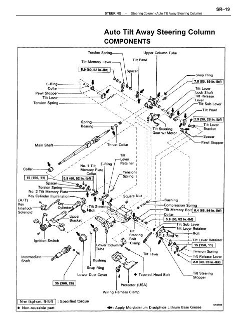
STEERING–<strong>Steering</strong> <strong>Column</strong> (<strong>Auto</strong> <strong>Tilt</strong> <strong>Away</strong> <strong>Steering</strong> <strong>Column</strong>)SR–19<strong>Auto</strong> <strong>Tilt</strong> <strong>Away</strong> <strong>Steering</strong> <strong>Column</strong>COMPONENTS
SR–20STEERING–<strong>Steering</strong> <strong>Column</strong> (<strong>Auto</strong> <strong>Tilt</strong> <strong>Away</strong> <strong>Steering</strong> <strong>Column</strong>)DISASSEMBLY OF STEERING COLUMN1. REMOVE IGNITION KEY CYLINDER ILLUMINATION2. REMOVE INTERMEDIATE SHAFT3, REMOVE WIRING HARNESS CLAMP4. (USA)REMOVE PROTECTOR5. REMOVE UPPER BRACKET(a) Using a centering punch, mark the center of thetapered–head bolts.(b) Using a 3–4 mm (0.12–0.16 in.) drill, drill into thetapered–head bolts.(c) Using a screw extractor, remove the tapered–headbolts.(d) Remove the two bolts, and separate the upperbracket and the column tube.6. REMOVE COMPRESSION SPRING(a) Using a torx wrench, remove the bolt and spring.Torx wrench: T30 (Part No. 09042–00010 or locallymanufactured tool)(b) Remove the two bushings from the spring.7. REMOVE THREE TENSION SPRINGS
STEERING–<strong>Steering</strong> <strong>Column</strong> (<strong>Auto</strong> <strong>Tilt</strong> <strong>Away</strong> <strong>Steering</strong> <strong>Column</strong>)SR–218. REMOVE TILT STEERING GEAR WITH MOTOR9. REMOVE E–RING AND COLLAR10. REMOVE TILT MEMORY LEVER, TORSION SPRINGAND SPACER(a) Remove the nut and two washers.(b) Remove the tilt memory lever, torsion spring andspacer.11. REMOVE SPACER. TORSION SPRING, NO. 1 ANDNO. 2 TILT MEMORY PLATES AND COLLARS(a) Remove the three nuts and two washers.(b) Remove the spacer, torsion spring, No. 1 and No. 2tilt memory plates.(c) Remove the two collars.12. REMOVE TILT RELEASE LEVER AND TILT LEVERRETAINER(a) Remove the four nuts and three washers.(b) Remove the tilt release lever and tilt lever retainer.
SR–22STEERING–<strong>Steering</strong> <strong>Column</strong> (<strong>Auto</strong> <strong>Tilt</strong> <strong>Away</strong> <strong>Steering</strong> <strong>Column</strong>)13. REMOVE BOLT, TILT LEVER RETAINERS AND TILTSTEERING STOPPER(a) Remove the two E–rings.(b) Pull out the bolt.(c) Remove the two tilt lever retainers and tilt steeringstopper.(d) Remove the tilt lever and tilt sub lever from the tiltlever retainer.14. REMOVE SPACER AND PAWL STOPPERS15. REMOVE TILT LEVER BRACKET AND TILT PAWLS(a) Remove the bolt and tilt lever bracket.(b) Remove the two tilt pawls.16. REMOVE TILT LEVER, TILT SUB LEVER, TILT RE-LEASE LEVER AND TILT LEVER LOCK SHAFT(a) Remove the tilt lever, tilt sub lever, and tilt releaselever.(b) Pull out the tilt lever lock shaft.
STEERING–<strong>Steering</strong> <strong>Column</strong> (<strong>Auto</strong> <strong>Tilt</strong> <strong>Away</strong> <strong>Steering</strong> <strong>Column</strong>)SR–2317. REMOVE UPPER COLUMN TUBE(a) Set SST, the nut (10 mm diameter, 1.25 mm pitch),plate washer (36 mm outer diameter) and bolt (10mm diameter, 1.25 mm pitch, 50 mm length) asshown.And then remove the two tilt steering bolts.SST 09910–00015 (09911–00011, 09912–00010)(Reference) Nut 90170–10004Plate washer 90201–10201Bolt 91111–51050(b) Remove the upper column tube from the lowercolumn tube.(c) Remove the collar from the main shaft.18. REMOVE MAIN SHAFT(a) Using SST to compress the main shaft spring, re–move the snap ring with snap ring pliers.SST 09950–20017(b) Remove the main shaft from the column tube.(c) Remove the spring, thrust collar and bearing.19. REMOVE COLLAR AND TILT MEMORY BOLT(a) Remove the nut and collar.(b) Using a hexagon wrench, remove the tilt memorybolt and square nut.
SR–24STEERING–<strong>Steering</strong> <strong>Column</strong> (<strong>Auto</strong> <strong>Tilt</strong> <strong>Away</strong> <strong>Steering</strong> <strong>Column</strong>)INSPECTION AND REPLACEMENT OFSTEERING COLUMN1. INSPECT KEY CYLINDERCheck that the steering lock mechanism operates prop–erly.2. IF NECESSARY, REPLACE KEY CYLINDER(a) Place the ignition key at the ACC position.(b) Push down the stop pin with a thin rod, and pull outthe key cylinder.(c) Make sure the ignition key is at the ACC position.(d) Install a new key cylinder.3. IF NECESSARY, REPLACE MAIN SHAFT BUSHING(a) Remove the snap ring.(b) Using a screwdriver, remove the bushing.(c) Align the holes of the tube and projections of anew bushing, and install the bushing to the columntube.(d) Install the snap ring.4. INSPECT UPPER BEARINGCheck the upper bearing rotation condition and check forabnormal noise.5. INSPECT KEY INTERLOCK SOLENOID(See page AT–182)
STEERING–<strong>Steering</strong> <strong>Column</strong> (<strong>Auto</strong> <strong>Tilt</strong> <strong>Away</strong> <strong>Steering</strong> <strong>Column</strong>)SR–25ASSEMBLY OF STEERING COLUMN(See page SR–19)1. APPLY MOLYBDENUM DISULPHID LITHIUM BASEGREASE (See page SR–19)2. INSTALL MAIN SHAFT(a) Install the bearing, thrust collar and spring to themain shaft.(b) Install the main shaft into the upper column tube.(c) Using SST to compress the main shaft spring, installthe snap ring with snap ring pliers.SST 09950–200173. SELECT TILT STEERING BOLTSSelect the bolt for the left or right side and then select thebolt for the other side as the left and right bolt havedifferent shapes.HINT: Select the bolt with the plain thread end whenthe upper column tube mark is 2, and the bolt with thehollow–tipped thread end when the mark is 1 .4. INSTALL MAIN SHAFT WITH UPPER COLUMN TUBE(a) Install the collar to the main shaft.(b) Install the main shaft with the upper column tubeinto the lower column tube.(c) Using a plastic hammer, drive in the tilt steeringbolts.NOTICE: Be careful not to mis–install the left andright bolts.
SR–26STEERING–<strong>Steering</strong> <strong>Column</strong> (<strong>Auto</strong> <strong>Tilt</strong> <strong>Away</strong> <strong>Steering</strong> <strong>Column</strong>)5. INSTALL TILT MEMORY BOLT AND COLLAR(a) Install the square nut and tilt memory bolt.(b) Using a hexagon wrench, torque the tilt memorybolt.Torque: 6.4 N–m (65 kgf–cm, 56 in.–lbf)(c) Install the collar.(d) Temporarily install the nut.HINT: Torque the nut after selecting the collar in step16.6. INSTALL TILT LEVER LOCK SHAFT, TILT RELEASELEVER, TILT SUB LEVER AND TILT LEVER(a) Install the tilt lever lock shaft into the upper col–umn tube.(b) Install the tilt release lever.(c) Install the tilt lever and tilt sub lever.7. INSTALL TILT PAWLS AND TILT LEVER BRACKET(a) Install the two tilt pawls to the upper column tube.HINT: Install the pawl pin into the long hole of the tiltlever and tilt sub lever.(b) Install the tilt lever bracket.(c) Install and torque the tilt lever bracket installationbolt.Torque: 2.9 N–m (30 kgf–cm, 26 in.–lbf)8. ENGAGE AND ADJUST TILT PAWL(a) Engage the tilt sub lever side pawl to the center ofthe ratchet.(b) While turning the tilt lever side collar, completelyengage the tilt lever side pawl to the ratchet.9. SELECT PAWL STOPPERS(a) With the tilt pawl and ratchet engaged, install twopawl stoppers.(b) Check that the alignment marks on the stopper andpawl align when the stopper is rotated to the pawlside.
SEZIONE 1. LO SCENARIO INTERNAZIONALE E NAZIONALEseconda metà degli anni Ottanta, anche come conseguenza dell’incidente diChernobyl, diversi paesi rallentavano o terminavano i loro programmi nucleari.Nonostante ciò, a livello europeo la generazione nucleare continuava a crescere, passandoda 575 TWh nel 1985 a oltre 850 TWh alla fine degli anni Novanta, aumentandocosì il suo contributo alla generazione lorda di oltre un terzo del totale.Nell’anno 2000, l’energia nucleare rappresentava la principale fonte di generazioneelettrica in Belgio, Francia e Svezia, in quest’ultimo paese a pari grado con l’energiaidroelettrica. In Finlandia, Germania, Spagna e Regno Unito l’energia nucleare rappresentavatra un quarto e un terzo della generazione totale. In questi paesi la generazionenucleare e termoelettrica da carbone copriva oltre il 50 per cento della generazionecomplessiva. L’energia nucleare giocava un ruolo marginale in Olanda dove lagenerazione è prevalentemente a base di gas naturale e da carbone. Nei rimanentisette paesi membri senza generazione nucleare, un ruolo determinante veniva svoltodal carbone (con oltre un terzo della generazione totale in Danimarca, Grecia, Irlandae Portogallo) o dall’energia idroelettrica (Austria). L’incidenza del petrolio era marginale(inferiore al 3 per cento) in sette Stati membri, significativa (fino al 20 per cento)in cinque paesi e notevole (fino al 33 per cento) nei rimanenti tre paesi, tra cui l’Italia.Nell’Unione europea l’incidenza del gas naturale nella generazione elettrica lorda è triplicata,passando da meno del 7 per cento a quasi il 19 per cento nel corso degli anniNovanta: tutti gli Stati membri hanno partecipato a questo aumento. Tuttavia, il ruolodel gas naturale è molto differenziato in funzione degli altri input alla generazione edelle sue risorse domestiche, raggiungendo nel 2000 un massimo prossimo al 60 percento in Olanda, valori superiori al 25 per cento in Belgio, Danimarca, Irlanda, Italia eRegno Unito, e valori tra 15 e 25 per cento in quasi tutti gli altri paesi. Nel 2000 la generazionea base di gas naturale era scarsamente importante solo in Francia, Germania eSvezia in cui, come già indicato, dominano l’energia nucleare, il carbone e l’energia idroelettricae nei paesi di più recente metanizzazione (Grecia, Portogallo e Spagna).È anche significativa la diversa concentrazione geografica delle fonti di generazionenel mercato europeo. Nel 2000, la generazione nucleare era concentrata per quasil’80 per cento in appena tre paesi, Francia, Germania e Regno Unito, mentre la generazioneda carbone lo era, per oltre l’80 per cento, in Germania, Regno Unito eSpagna. Analogamente, poco meno dell’80 per cento della generazione da gas naturaleera concentrata in Regno Unito, Italia, Germania e Olanda. Il contributo delpetrolio riguardava, per il 62 per cento, solo Italia e Spagna. La generazione idroelettricae da altre fonti rinnovabili era più distribuita, con poco più del 70 per centoin cinque paesi (Austria, Francia, Italia, Spagna e Svezia).10
SR–28STEERING–<strong>Steering</strong> <strong>Column</strong> (<strong>Auto</strong> <strong>Tilt</strong> <strong>Away</strong> <strong>Steering</strong> <strong>Column</strong>)13. INSTALL COLLARS, NO. 1 AND NO. 2 TILT MEMORYPLATES, TORSION SPRING AND SPACER(a) Install the two collars.(b) Install No. 1 and No. 2 tilt memory plates.(c) Install the two washers and nuts.(d) Torque the two nuts.Torque: 5.9 N–m (60 kgf–cm, 52 in.–lbf)(e) Install the torsion spring to the tilt steering bolt sothat the spring clips onto No. 1 memory plate andthe tilt lever retainer. Then install the spacer and nutto the steering bolt.Torque: 15 N–m (150 kgf–cm, 17 ft–lbf)14. INSTALL SPACER, TORSION SPRING AND TILTMEMORY LEVER(a) Install the spacer, torsion spring and tilt memorylever.(b) Install two washers and nut.(c) Check that on both sides the pawl and ratchet arefully engaged.(d) Tighten the nut.Torque: 5.9 N–m (60 kgf–cm, 52 in–lbf)(e) Check that the pawls rotate smoothly.15. INSTALL COLLAR AND E–RING16. SELECT COLLAR(a) Put the steering column in tilt away position.(b) Push the upper column tube downward and installthe collar between the tilt memory bolt and tiltlever retainer.Select a collar with an outer diameter one rank be–low the collar which fits most tightly.ColorBlueYellow–PlatedPink–PlatedNoneBlack–PlatedRedGreenPinkOuter diametermm (in.)12.75 – 12.85 (0.5020 – 0.5059)12.55 – 12.65 (0.4941 – 0.4980)12.35 – 12.45 (0.4862 – 0.4902)12.15 – 12.25 (0.4783 – 0.4823)11.95 – 12.05 (0.4705 – 0.4744)11.75 – 11.85 (0.4610 – 0.4665)11.55 – 11.65 (0.4547 – 0.4587)11.25 – 11.35 (0.4429 – 0.4468)
STEERING–<strong>Steering</strong> <strong>Column</strong> (<strong>Auto</strong> <strong>Tilt</strong> <strong>Away</strong> <strong>Steering</strong> <strong>Column</strong>)SR–2917. INSTALL TILT STEERING GEAR WITH MOTORinstall the tilt release lever pin into the long hole of thesteering gear lever.18. INSTALL THREE TENSION SPRINGS19. INSTALL COMPRESSION SPRING(a) Install the two bushings to the spring.(b) Install the spring and bolt.(c) Using a torx wrench, tighten the bolt.Torx wrench: T30 (Part No. 09042–00010 or locallymanufactured tool)Torque: 7.8 N–m (80 kgf–cm, 69 in.–lbf)20. INSTALL UPPER BRACKET(a) Install the upper bracket with two new tapered–head bolts.HINT: Install the upper bracket pin into the columntube hole.(b) Tighten the tapered–head bolts until the bolt headsbreak off.21. (USA)INSTALL PROTECTOR22. INSTALL WIRING HARNESS CLAMP23. INSTALL INTERMEDIATE SHAFTTorque: 35 N–m (360 kgf–cm, 26 ft–lbf)24. INSTALL IGNITION KEY CYLINDER ILLUMINATION
SR–30STEERING–<strong>Steering</strong> <strong>Column</strong> (<strong>Auto</strong> <strong>Tilt</strong> <strong>Away</strong> <strong>Steering</strong> <strong>Column</strong>)ELECTRONIC CONTROL SYSTEMComponents and Circuit
STEERING–<strong>Steering</strong> <strong>Column</strong> (<strong>Auto</strong> <strong>Tilt</strong> <strong>Away</strong> <strong>Steering</strong> <strong>Column</strong>)SR–31Troubleshooting Flow–ChartCheck battery positive voltage.8 V or moreLess than 8 VCheck battery and charging system.Is POWER fuse normal?YesReplace fuse.Is operation normal?Fuse faulty.YesShort circuit in wire harness betweenfuse and tilt steering ECU terminal B+.Disconnect the ECU connector.Check 1.Check that there is the battery positive voltage between the tiltsteering ECU terminal B+ and body ground.YesOpen circuit in wire harness between the fuse and tilt steering ECU terminal B+.Check 2.Check that there is continuity between the tilt steering ECUterminal GND and body ground.Yes• Open circuit in wire harness between the tilt steering ECU terminalGND and body ground.• Body ground faulty.CONTINUED ON NEXT PAGE
SR–32STEERING–<strong>Steering</strong> <strong>Column</strong> (<strong>Auto</strong> <strong>Tilt</strong> <strong>Away</strong> <strong>Steering</strong> <strong>Column</strong>)YesCONTINUED FROM PREVIOUS PAGECheck 3.Check continuity between the tilt steering ECU terminals UWSWand GND.• Ignition switch is inserted . . . Continuity• Ignition switch is removed ... No continuityYes• Open or short circuit in wire harness between the tilt steering ECUterminal UWSW and unlock warning switch.• Unlock warning switch faulty.Check 4.Check voltage between the tilt steering ECU terminals IGSW andGND.0 Ignition switch ON ... Battery positive voltage0 Ignition switch OFF ... 0 VYesOpen or short circuit in wire harness between the tilt steering ECUterminal IGSV1l and ignition switch.Check 5.Check that there is continuity between terminals TiM + and TIM–Yes• Open circuit in wire harness between the terminals TiM + and TIM–.• <strong>Tilt</strong> steering motor faulty. (See page SR–33)Check 6.Inspect tilt steeringECU. (See pageSR–33)BadReplace tilt steeringECU.


