Chapter - Kostic - Northern Illinois University
Chapter - Kostic - Northern Illinois University
Chapter - Kostic - Northern Illinois University

Create successful ePaper yourself
Turn your PDF publications into a flip-book with our unique Google optimized e-Paper software.
Critical Issues in Nanofluids Research and Application Potentials 5pumping power. Therefore, further experimental research is required in that area in order toimprove flow properties and to determine the feasibility of nanofluids.Nanofluids of various qualities have been produced mainly in small volumes and forresearch purposes, but large-scale production at low cost of well-dispersed, stable nanofluidsis required for commercial applications. The lack of large-scale production is a major barrierto testing and use of nanofluids in the transportation, industry and other applications.Most of the nanofluids used in research so far are produced by a two-step process. First,nanoparticles are produced as a dry powder, typically by inert gas condensation [16]. Thesecond step involves dispersion of dry nanoparticle powder into a base fluid, like water, oil orethylene-glycol. An advantage of the two-step process is that the inert-gas condensationtechnique has been scaled up to commercial nano-powder production [18]. A deficiency ofthis method is the tendency of nano-powders to agglomerate during storage and dispersion inthe base fluids, particularly with heavier metallic nanoparticles. Surfactants and other surfacestabilizationadditives can be used to achieve more homogeneous and more stablesuspensions, however they may influence the nanofluids properties. In addition to mechanicalmixing, ultra-sonic mixers are used to break up agglomerates and give more uniformdispersions. In general, although the process works well for some oxides, it has not been ableto yield metallic nanofluids with substantially enhanced thermal conductivity.By contrast, the one-step physical and chemical methods have potential to produce betterquality nanofluids. For example, a physical one-step method consists of a direct-evaporationprocess, involving nanoparticle source evaporation and direct condensation and dispersiononto the base fluid in a single step. This method has been developed by Yatsuya et al. [19]and improved by Wagner et. al. [20]. The one-step method has been employed by Choi andEastman [21] in Argonne National Laboratory (ANL) and successfully used to producenanofluids with very small copper nanoparticles (about 10 nm) and exceptionally highthermal conductivity [22]. However, the one-step process is intrinsically more difficult toreproduce, since particles cannot be characterized and pre-sorted before addition to the fluid.Consequently, the ANL method, although an excellent idea, needed to be substantiallyimproved in order to yield improved control of nanoparticle sizes and sustained nanofluidproduction. The improvement of the Argonne one-step method for nanofluid production hasbeen realized and a U.S. patent has been issued recently (<strong>Kostic</strong> et. al [23]). Details of theimprovement will be presented below.2.1. Improvement of Physical One-Step Production MethodFor nanofluids with high-conductivity metals such as copper, a single-step technique ispreferable to the two-step process to enhance dispersion and prevent oxidation of theparticles. Argonne National Laboratory developed a one-step physical method for creatingnanofluids, by nanoparticles being formed and dispersed in a fluid in a single process. Thispatented single step method involves direct evaporation and has been used to produce nonagglomeratingcopper nanoparticles that remain uniformly dispersed and stably suspended inethylene glycol [21]. The technique consists of condensing nanoparticles from the vaporphase directly into a flowing low-vapor-pressure ethylene glycol or oil in a vacuum chamber.The well-dispersed nanofluids of Cu in ethylene glycol enhance the thermal conductivity ofthe base fluid by up to 40% at the particle volume concentration of 0.3 %, significantly larger
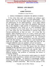
6Milivoje M. <strong>Kostic</strong>than the prediction of effective medium theory [22]. Although the one-step physical methodhas produced nanofluids in small quantities for research purposes, it has a number ofdeficiencies, and needed to be improved, since lack of consistent nanofluid production limitsthe progress of the future research in this and related areas.Figure 1. Improved new-design for the one-step, direct-evaporation nanofluid production apparatus(U.S. Patent No. 7,718,033) [23].An improved “One-step method for the production of nanofluids” has been developedand a U.S. patent has been issued recently [23], see also Figure 1. The improved method andsystem is provided for producing nanofluids by a so called one-step direct metal evaporationand its deposition on a moving liquid film and further dispersion and mixing of nanoparticleswithin the fluid.The improved method and system is achieved by the following: better positioning(longitudinal instead of crosswise) and variable-adjustable distance between the metalevaporation source and liquid film, which achieves smaller particle deposition path andsmaller fluid-film exposure over the heated source and thus smaller nanoparticle size, but atthe same time it provides larger liquid film area and thus larger deposition rate. Furthermore,better heater evaporation source insulation reduces the heating power which is possible to bebalanced by an improved new heat-exchanger design of nitrogen cooler and increased drumrotation, thus providing lower liquid temperature and pressure which contributes to smallernanoparticle size, and provides for continuous, steady-state production of nanofluids withdesired nanoparticle size distribution. Additional improvement features include a liquid feedin,inert gas flashing, visual observation, and better process heating control, all of whichfurther contribute to continuous, steady-state operation and control of temperature andpressure for production and optimization of desired nanofluid qualities and quantities.The improved one-step process and system for production of nanofluids includes placinga base fluid, such as ethylene glycol or oil, in a rotating cylindrical drum situated in a vacuumchamber. The rotating axis of the drum is preferably horizontal, and the drum with solid back-
Critical Issues in Nanofluids Research and Application Potentials 7endplate contains annular front-endplate to prevent the liquid from running out but providingentrance for metal evaporator heater and nitrogen cooler elements. An electric motor rotatesthe drum at a designated rotational speed. As the drum rotates, it drags liquid filled in thebottom part of the drum along its inside cylindrical surface, forming a thin film of liquid onthe inner surface above the pool of liquid in the bottom of the drum. An evaporation boatheater is positioned in close proximity to the upper inside surface of the cylindrical drum. Themetal evaporates at a given rate and the gaseous molecules rise outwards and condense ontothe liquid film on the revolving drum. The liquid is cooled by inserting a metallic heatexchanger in the liquid and passing liquid nitrogen through the exchanger. In a steady-stateprocess, the cooling capacity of the heat exchanger balances the heat input from theevaporator and heat gains from the surroundings.In a most preferred form of the invention, the method and system includes: (a) strategicpositioning of the boat-heater that evaporates the metal close to the moving liquid film in theaxial drum direction, instead of perpendicular to the drum axis, and with adjustable spacing ofthe evaporator relative to the liquid film; (b) a boat/heater that is thermally well insulated withfoam, foil and radiation shields; (c) better liquid cooling by substantially increasing drumrotational speed, improving the design of the heat exchanger that cools the base liquid withliquid nitrogen flow, including optimized cooler-to-drum gap and fin spacing, and addition ofcooling fins to the rotating drum if needed; and (d) well controlled, adjustable evaporatortemperature and balanced cooling to provide for desired nanoparticle size distribution in asteady-state process, for controlled and continuous nanoparticle production.This improved process and system allows for much better process control with theresulting improvement in the quality and quantity of the nanofluids produced by the process.The system improvements, such as placement of the boat/heater evaporator closer to the topof the rotating drum, increasing the drum rotation speed, and use of fins to increase surfacearea for cooling, give rise to numerous advantages. These and other improvements aredescribed in much greater detail elsewhere [23].3. NANOFLUIDS STABILITY AND INFLUENCE OF ADDITIVES:FRICTION-DRAG REDUCTION AND ISSUE OF HEAT-TRANSFERREDUCTION (DEVELOPMENT OF POLYMER-NANOFLUIDS)As already stated, the conglomeration and clustering of nanoparticles in the nanofluidmixture is taking place before and after the nanofluid is made and during its use, and dependson many factors, especially on additives used. Two nanofluid samples with all of theparameters being the same but different type and amount of surfactants and/or pH adjustersused, may result in quite different thermo-physical properties and flow and heat-transfercharacteristics of apparently the same nanofluids. These and other unknown factors mayexplain anomalous and controversial results obtained by different researches.The particle size distribution of nanoparticles is another important factor and reportingthe average particle size is not sufficient to characterize a nanofluid. It is also known thatcylindrical and rod-shaped particles offer higher thermal enhancement when compared tospherical particles. More consistent research should be made for the investigation of theproperties and thermal performance of well-characterized ‘static’ and dynamic constitution of
8Milivoje M. <strong>Kostic</strong>nanofluids, since there are more hypothetical theories proposed than reliable results to verifythose theoretical models.In addition to investigating the effects of basic parameters such as particle size, basefluid, and particle volume fraction, the researchers should well control and report allimportant parameters, including additives used, details of ultrasonic treatment, and others. Nowonder that effects of many parameters on the thermal conductivity and viscosity ofnanofluids has not been fully understood yet, which are important prerequisites for betterunderstanding, development and optimization of nanofluid flow and thermal performance.Another important, but overlooked issue with use of additives in nanofluids is apossibility to drastically reduce friction drug in turbulent flow (desired effect; used in Trans-Alaska oil pipeline system), which is usually accompanied with commensurate heat-transferreduction, the letter being an undesirable, adverse effect. These drag and heat-transferreduction phenomena, described next, are well-known by some researchers but are not widelyknown and thus overlooked by nanofluid researchers.3.1. Friction-Drag Reduction and Issue of Heat-Transfer Reduction --Development of Polymer-NanofluidsA class of fluids, known as “drag-reduction” fluids, has intrigued many investigators,ever since Toms’ discovery [24] that the friction drag of common fluids with minuteconcentrations of certain polymer additives, under turbulent flow conditions, is considerablysmaller (several times) than the expected values. Drag-reduction fluids are also nanofluids,i.e. solutions of minute concentrations of certain nano-size (sometimes micro-size) additives,like high-polymers, soap and surfactant aggregates, or fibers, in common fluids, like water oroil. The pressure drop and heat-transfer in turbulent pipe with drag-reducing fluids (classifiedas non-Newtonian fluids if with higher concentration of additives) is several times lower thanfor the corresponding Newtonian fluids as discussed in an extensive review by Metzner [25].These phenomena can be characterized by the so-called Virk’s minimum asymptotic frictionvalue [26]. Unfortunately, heat-transfer is also reduced. Hartnett and <strong>Kostic</strong> [27] have studdedthe drag-reducing fluids in laminar non-circular duct flows and discovered enhanced heattransfer. They reviewed the flow and heat transfer phenomena of Newtonian and non-Newtonian fluids in rectangular ducts [27], and <strong>Kostic</strong> [28] presented an overview onturbulent drag and heat transfer reduction and laminar heat transfer enhancement of certainnon-Newtonian fluids in non-circular duct flows.Complex fluids, like polymer solutions have functional, process-adjusting, activemolecular-structures, and exhibit well-known shear-rate dependent viscosity, see Figure 2.Randomly-oriented, long-chain macro-molecules increase substantially the zero-shear-rate(zero velocity) solution viscosity, but under shearing stresses, they self-align with the flowand viscosity is substantially reduced with the shear-rate increase. This is more dramaticallydemonstrated in turbulent flow, where a minute concentration (50 ppm) of long-chainmacromolecules may reduce turbulent friction fivefold by suppressing transverse turbulencefluctuations, and in turn substantially reduce turbulence dissipation and over-all friction, seeFigure 3 [28]. Regrettably, the turbulent heat transfer is commensurately reduced. Similarly,the nanoparticles could re-align and process-adjust during flow and heat-transfer processes.There is a need to selectively choose or develop new nanoparticles and drag-reduction
Critical Issues in Nanofluids Research and Application Potentials 9additives to optimize flow and heat transfer characteristics of hybrid nanoparticle+additivebased nanofluids.Figure 2. Shear-rate dependent viscosity due to process-adjusting active structure of an aqueouspolymer solution [28].Figure 3. Friction-factor vs. Reynolds-number curves for laminar, turbulent, and polymer drag-reducingasymptotic flows (in semi-log scale as opposed to usual log-log scale) [28].
10Milivoje M. <strong>Kostic</strong>The polymer-nanofluids, could be developed, and are expected to be even more complexand active fluid mixtures, and thus have more degrees-of-freedom to ‘self-adjust’ underdifferent process- and/or field-conditions. To develop, study, understand, and optimizepolymer-nanofluid functionalities, by reducing instabilities while promoting those fluidstructural activities that enhance flow and heat transfer characteristics as well as othercharacteristics, will be a research challenge and potential for many applications.Another research challenge could be to combine the selected nanoparticles and dragreducingadditives, and thus develop and optimize a Drag-Reducing nanofluid (dubbed hereDR-nanofluid). The expectation is to obtain a hybrid nanofluid with improved flow and heattransfer characteristics. The drag-reducing fluids may contain water, different co-solvents,lubricants, co-polymer emulsions, dispersants and surfactants, rheological agents, surfaceenergy controlled agents, and pH and ionic strength adjusting agents. The formulationprinciple and techniques for drag-reducing fluids and nanofluids should be similar to thoseformulations of water-based organic-inorganic hybrid emulsions. Different techniques couldbe developed and employed to synthesize and formulate the nanofluids with polymeradditives.Furthermore, developing nanofluids with polymer additives or “POLY-nanofluids” mayhave other applications, beyond the advanced heat-transfer fluids, for creating morefunctional nanostructures, since polymer molecules may provide an enhanced web-likestructure for nanoparticles in base fluids. Development of nanofluids, with enhanced orentirely different properties from their base fluids, is a new challenge and opportunity, andmay have unprecedented application potentials, not only in thermal management and efficientcooling, but also in industry, buildings, environmental and bio-medical applications, as wellas emerging critical applications.4. THERMAL CONDUCTIVITY MEASUREMENTS: POSSIBLE ISSUESWITH NANOFLUIDSThermal conductivity measurements of suspensions of nanoparticles in common, basefluids conducted in Argonne national Laboratory almost two decades ago, discovered“anomalous” enhancement of thermal conductivity, compared to the suspensions of the sametype and concentration but larger-size particles, and as “expected” values, predicted with theheterogeneous mixture theory. The “nanofluid” name was introduced to represent suchsuspension of nano-particles in a common fluid. Exceptional enhancement of nanofluidsthermal conductivity and potential for development of substantially improved heat transferfluids, have propelled research and publications, almost exponentially. A number of reviewarticles have been published [1-6], and more recent extensive experimental investigation [29].Most of the measured results, reviewed in the above references, show significantenhancement of nanofluids thermal conductivity (TC), but some with large discrepancy in thevalues, while some others without significant enhancement over predictions of classicalmixture theory [30]. Usually, three measurement methods have been used: steady-statemethod; transient oscillation method, and in most cases the transient Hot-Wire ThermalConductivity (HWTC) method. In addition to the enhancement of nanofluids TC withnanoparticle concentration, a strong dependence of TC on temperature is observed. Since the
Critical Issues in Nanofluids Research and Application Potentials 11measured nanofluids TC enhancement has not been understood and justified yet, there is aneed to investigate influence of measurement methods on the obtained results, since allapparatus calibration have been performed with classical fluids with known TC. However,there may be some unknown issues with measurements of complex and dynamic (usuallyunstable) nanofluid structures. For example, influence of electromagnetic fields on nanoparticlefluid molecule interactions, possible nano-convection effects related to measurementmethods, or influence of temperature gradients on TC results.Therefore, in this section, only a couple of selected issues will be covered, namely, aproposed improvement of a Hot-Wire Thermal Conductivity (HWTC) apparatus, and a designand comparative measurement using steady-state Parallel-Plate Thermal Conductivity (PPTC)apparatus. Both are described in details to facilitate their replication and possible futureimprovements.A new and improved HWTC apparatus for thermal conductivity measurements ofcommon fluids and nanofluids has been recently developed, designed and fabricated [31, 32].A platinum (Pt) wire of 50.8 µm diameter with a Teflon insulation coating of 25.4 µmthickness was used as the hot-wire heater and temperature sensor for the present application.The new apparatus employs innovative solutions for easy calibration of uniform Pt-wiretension and thus minimizing the strain influence on temperature measurement (i.e.,minimizing the well-known and unwanted “strain-gage effect” on Pt-wire electricalresistivity); measurement of Pt-wire voltage drop independently from power wiring (fourwires); and an effective off-centered mechanical design to minimize the test fluid sample size(about 35 mL), but at the same time providing additional space for wiring, including threeinside thermocouples for fluid temperature uniformity verification. Data acquisition hardwareand LabVIEW® application software are optimized to minimize signal noise and enhanceacquisition and processing of useful data.In addition, a steady-state, parallel-plate thermal conductivity (PPTC) apparatus has beendeveloped and used for comparative measurements of complex POLY-nanofluids [33, 34], inorder to compare results with the corresponding measurements using the transient, hot-wirethermal conductivity (HWTC) apparatus. The related measurements in the literature, mostlywith HWTC method, have been inconsistent and with measured thermal conductivities farbeyond prediction using the well-known mixture theory [30]. The objective was to check outif existing and well-established HWTC method might have some unknown issues whilemeasuring TC of complex nano-mixture suspensions, like electro-magnetic phenomena,undetectable hot-wire vibrations, and others.These initial and limited measurements have shown considerable difference between thetwo methods, where the TC enhancements measured with PPTC apparatus were about threetimes smaller than with HWTC apparatus, the former data being much closer to the mixturetheory prediction. However, the influence of measurement method is not conclusive since ithas been observed that the complex nano-mixture suspensions were very unstable during thelengthy steady-state measurements as compared to rather quick transient HWTC method. Thenanofluid suspension instability might be the main reason for very inconsistent results in theliterature. It is necessary to expend investigation with more stable nano-mixture suspensions.
12Milivoje M. <strong>Kostic</strong>4.1. Improved, Transient Hot-Wire Thermal Conductivity (HWTC)Apparatus for NanofluidsA new and improved, transient hot-wire thermal conductivity apparatus has beendeveloped to measure the thermal conductivity of fluids, polymer solution, nanofluids andpoly-nanofluids (a mixture of nano particles, polymers and conventional heat transfer fluids)[31, 32]. The apparatus is a part of a research program at <strong>Northern</strong> <strong>Illinois</strong> <strong>University</strong> with anobjective to resolve some critical issues in nanofluids research and to develop and optimizenew hybrid, drag-reducing polymer-nanofluids with enhanced thermo-physical characteristics[36, 37]. Thermal conductivity, a measure of material’s ability to conduct heat, is a veryimportant property for thermal analysis.The mathematical model for the hot-wire method is based on an ideal, infinitely long andthin continuous line source dissipating heat, of heat flux q per unit length, applied at time t =0, in an infinite and incompressible medium. The general assumption is that heat transfer tothe infinite medium, of thermal conductivity k fand thermal diffusivity f k f f C f, isby conduction alone and thus increases the both temperatures in time, of the heat-source andtest-medium. It is also assumed that the line heat-source has uniform instant temperatureeverywhere, but transient in time (virtually achieved with small diameter and long wire withlarge thermal conductivity and/or small heat capacity). The governing equation is derivedfrom the Fourier’s equation for one-dimensional (1-D) transient heat conduction in cylindricalcoordinates,1fTt1 T rr r r(1)where, T T0 Tis the temperature of the medium at any time, t and arbitrary radialdistance, r ; T 0 is the initial temperature of the source and medium, and T is thetemperature difference between the medium and initial temperature. The Eq. (1) is the subjectof the following boundary conditions: Tqlimr r2r0k fat t 0 and r 0 , (2)limrTr,t0at 0t and r , (3)where, fand C fare density and specific heat capacity of the test medium, respectively.The infinite series solution of this problem is outlined by Carslaw and Jaeger [38]. After2initial, short transient period (i.e., t r 4; note, this transiency is much longer for finitefwire diameter, including insolation if any), except for the first term containing time t, thehigher order terms could be neglected, resulting in a very good approximation as,
Critical Issues in Nanofluids Research and Application Potentials 13q 4f t T T ( r,t)T 0 ln24kf r (4)where =0.5772 is the Euler’s constant.For constant fluid medium properties and a fixed and arbitrary radius r, afterdifferentiation of Eq. (4), the radius is eliminated from the equation, and the followingrelation is obtained,k fq 1 (5)4 d tT / d ln( )Therefore, if temperature of the medium is measured as function of time at any fixedradial position, including at the contact with the line source (i.e. the temperature of the ‘thin’line source), the thermal conductivity of the test medium, kf, is proportional to the sourceheat flux and inversely proportional to the temperature (or temperature difference) gradientwith regard to the natural logarithm of time, see Eq. (5).The advantage of the hot-wire method is its simplicity and consequently low cost ofconstruction. Furthermore, the wire itself acts as both the heating source and temperaturesensor for measurement. Another advantage is that convection heat transfer effects can beminimized and identified when present as deviation of the linearity in the plot of T as afunction of ln(t).4.1.1. Application of Hot-Wire Method for NanofluidsA bare metal wire centered in a fluid medium is generally used for thermal conductivitymeasurement of fluids by the transient hot-wire method. Nanofluids containing metalparticles are electrically conductive, so application of a bare wire could lead to ambiguousresults in the measurements. Some of the problems identified by Nagasaka and Nagashima[39] in the application of the ordinary transient hot-wire method to electrically conductingliquids are: (a) possible current flow through the liquid, resulting in ambiguous measurementof heat generated in the wire; (b) polarization of the wire surface; (c) distortion of outputvoltage signal due to influence of the conducting liquid cell.In order to overcome these errors, it is recommended that the bare metal wire should becoated using electrically insulating material. The effect on temperature distribution due to thininsulation coating has been analyzed [39] and outlined by Yamasue et al. [40]. Thetemperature rise Tof the hot-wire is given as,Tq4kf 1lnt Ao tB lnt C oo(6)The termsA o ,B o andC o are defined as follows:
14Milivoje M. <strong>Kostic</strong> 4f 2kf r klno fAo ln ...2 ro kirw2kw(7)Bo1 k 2 kikw2 f ki r w ro(8)2kf i w f i Co2rw kf ki1 1 4 2 8 k w w i i w 22r o 1 1 rw kikw ro ln2 f i k i i w r w 1 k42 kik w2 f k i f rw r o ln22k f i w f i ro(9)where, r w is the radius of the wire; and r o is the sum of the radius of the wire r w and theinsulation thickness i . Subscripts w, I, and f represent wire, insulation coating, and liquid,respectively.1 t B lnt is due to theComparison of Eq. (4) and (6) indicates that the term oC opresence of the insulation layer on the wire. If the term tBlnt 1oC ois negligiblysmall compared to the ln t A o term, then the constant A o shifts (i.e., offsets) the plot of T against ln(t), without changing the slope. Therefore, the thermal conductivity, k f , isagain accurately determined using Eq. (5). Yu and Choi have analyzed the wire temperaturerise as a function of time, to determine the influence of insulation coating on the thermalconductivity measurement and have concluded that relative measurement error of thermalconductivity is negligible if the slope of T against ln(t) is measured at later times after startof heating, and that no correction to insulation coating is necessary, even if the insulationcoating thickness is comparable to the wire radius.Electrical insulation coating to bare metal wire has been recommended for electricallyconducting fluids. Nagasaka and Nagashima [39] have coated the platinum wire (diameter 40µm) with polyester insulation (thickness 7.5 µm) to measure electrically conducting aqueousNaCl solution. Whereas, Perkins [41] anodized a tantalum wire (diameter 25.4 µm) to form anelectrically insulating layer of tantalum peroxide (thickness 70 nm), Yu et al. [42] haveapplied an epoxy insulation coating (estimated thickness 10 µm) to a platinum wire (diameter76.2 µm) to measure thermal conductivity of nanofluids. Jwo et al. [43] insulated a Nickel-Chromium alloy wire with Teflon to measure thermal conductivity of CuO nanofluids. Morerecently, Ma [44] in his thesis has utilized a platinum wire (diameter 25 µm) with an Isonelinsulation coating (thickness 1.5 µm) to measure thermal conductivity of variouscombinations of nano crystalline material and base fluids.
16Milivoje M. <strong>Kostic</strong>In our design [32], the length of the platinum hot-wire was taken as L w = 0.1484 m,based on the 0.139 m minimum length of hot-wire, determined according to Kierkus et al.[45] criteria, for our application data. Based on Healy et al. [46] criteria, the minimum hotwirecell outer boundary radius was determined as 0.0028 m, but chosen to be R= 0.00718 m, and the finite length of the sample to be L c = 0.170 m. The overall samplevolume V c after fabrication is calibrated to be 35 ml.A cross sectional view of the newly designed hot-wire thermal conductivity apparatuswith major mechanical components is shown in Figure 4. The major assembly components ofthe apparatus’ cell are: base plate, outer shell, and cell cap with hot-wire. The cell base platewith a threaded hole at the center of the plate (sealed by a Teflon washer) is used forconvenient assembling and disassembling the outer shell. The outer shell with 17.4 mm innerdiameter acts as the sample test fluid reservoir. The cell cap, designed to slide-fit into theouter shell, is hollow inside. The inner semi-circular hot-wire holder with an alignment ring issoldered at the lower end at an offset. A hot-wire guiding block, sliding tube, tension spring,and spring rod are all aligned at an offset inside the cap. The Teflon-coated platinum wire isindirectly connected to the tension spring via copper wires and a sliding rod, which arealigned with the spring mechanism (i.e., sliding tube, tension spring, spring rod and lockingnut). A locking nut, fastened to the spring rod, is mounted on the top of the cap. Twosymmetric rectangular cuts in the cap provide an opening for routing of electrical andthermocouple wires. A connector and calibration gauge holder and a wire holder, made ofTeflon, are mounted on the top and middle section of the cell cap.cFigure 5. Fabricated transient hot-wire thermal conductivity apparatus.Three thermocouples, mounted on the outer radius of inner semi-circular hot-wire holderat 15º, 45º and 75º angles, along the length of the sample test section, monitor uniformity of
Critical Issues in Nanofluids Research and Application Potentials 17the test fluid temperature. The thermocouple tip is bent towards the platinum hot-wire throughthe holes on the inner semi-circular hot-wire holder.Two copper wires at the top soldered-joint of the platinum hot-wire are passedsymmetrically through a sliding tube. The inner hollow portion of the sliding tube is filledwith epoxy to couple the copper wires with the sliding tube. A clearance between the slidingtube and hot-wire guiding block hole ensure near-frictionless motion of the sliding tube. Thespring rod is specially shaped to have external threads. A locking nut and spring rod arescrewed together like a nut and bolt. The special shaped sliding fit hole avoids turning of thespring rod when the locking nut is turned for adjusting the tension of the hot-wire. Thelocking nut has been fabricated to a specific weight that is used for calibration of the platinumhot-wire tension, within 50% of its ultimate tensile strength. An inverted L-shaped gauge hasbeen seated on the holder for calibrating the hot-wire tension and guarding the spring rodmovement. One of the two copper wires at another soldered joint of the platinum hot-wire ispassed through the off-centered hole of the alignment ring, while the other has been guidedthrough a hole in the inner semi-circular hot-wire holder. The copper wires at the alignmentring act as fixed rigid ends of the hot-wire.The present cell parameters are L c = 0.170 m, 2R c = 0.01437 m, V c = 35 ml,L c /2R c = 11.83. The parameters of the platinum hot-wire with Teflon coating of thickness25.4 µm are L w = 0.1484 m, 2r w = 50.8 µm, L w /2r w = 2921, 2R c /2r w = 282.9, andL w /2R c = 10.33.The controlled tightness of the thin platinum hot-wire is a very important aspect. Aninnovative solution, to indirectly connect a tension spring to the platinum hot-wire, whilemaintaining constant tension, has been incorporated. Also, a unique solution to calibrate theplatinum hot-wire tension has been developed. This arrangement minimizes the well knownand unwanted strain gage effect on hot-wire electrical resistivity, thus decreasing the straininfluence on temperature measurement. An extension spring with a low spring constant iscalibrated and used for present application as detailed elsewhere [31].4.1.3. Instrumentation and Data AcquisitionA Wheatstone bridge circuit has been employed to measure the resistance change of thehot-wire, with the wire being one of the arms (i.e., resistors) of the bridge. Initially, the bridgeis balanced until the voltage output of 10-15 µV is achieved. The bridge balancing isperformed within a brief period of time, using a constant, low input voltage of 0.1 V, tominimize heating of the platinum wire during initial bridge balancing. After the bridge circuitis balanced, a constant, input voltage V in , at start-time t = 0, is applied to heat the wire, thusresulting in unbalancing of the bridge due to the hot-wire’s temperature and thus resistancechange. The bridge input V in and output V out voltages are measured using a computerized dataacquisition system. A schematic diagram of the Wheatstone bridge circuit used formeasurement is shown in Figure 6. The circuit has been fabricated in such a way that the dataacquisition system can be easily connected and disconnected for measurement. The schematicof DAQ system is also shown in Figure 6.
18Milivoje M. <strong>Kostic</strong>Figure 6. Schematics of electrical circuit with computerized data acquisition system.Six different signals are measured using National Instruments’ dataacquisition (DAQ) hardware, namely: bridge voltage output; bridge voltage input; hot-wirevoltage drop (i.e., voltage drop across platinum wire); and three signals from thethermocouples mounted across the length of the hot-wire cell at the top, middle, and bottomsections. A computer program for acquiring and post-processing the measured data isdeveloped using the LabVIEW ® application software.All measurement parameters are controlled using the LabVIEW ® user interface. Theinput voltage range is configured at 0 – 10 V. The bridge voltage output is triggered after thevoltage threshold reaches a value of 1 mV. The voltage output channel can be configured to amaximum sampling rate is 100 Hz, with nominal operation range configured at 0 – 200 mV,which provides an overall measurement gain of 100. The bridge voltage output and time aremeasured and stored simultaneously. Post-processing of the acquired data is then performedin order to calculate the resistance change, temperature change, heat input, and then thermalconductivity of the test fluid.4.1.4. Calibration and Uncertainty AnalysisTwo standard base fluids of well-defined thermal conductivity, ethylene glycol anddistilled water, have been used for over-all calibration of the apparatus. The voltage change(i.e., bridge voltage output) for all calibration measurements has been acquired at a samplingrate of 50 Hz. For a typical measurement, the resistances of the Wheatstone bridge circuit aremeasured as: R 1 = 2270.6 Ω, R 2 = 2161.1 Ω, and R 3 = 7.715 Ω, using a four-wire resistancemeasurement technique. The reference resistance of the platinum wire is determined as R w 0
Critical Issues in Nanofluids Research and Application Potentials 19= 8.106 Ω using relevant correlations [1]. The measured length of platinum hot-wire was Lw= 0.1484 m. The platinum temperature coefficient of resistance is TCR Z Rw, where Rw= 8.22 Ω is the resistance measured at 20°C and Z = 0.02652 Ω/°C is the slope of the hotwireresistance with regard to temperature.Figure 7 shows a typical hot-wire temperature change versus time for ethylene glycol andwater. Analysis of the graph indicates that the linearity of the wire temperature change (insemi-log coordinate system) is obtained one second after the experiment starts. The initialdeviation from linear temperature change is due to initial transience (where Eq. 5 withouttruncated higher-order terms is not valid). This initial non-linear response is often overlookedor neglected in the references but may contribute to errors in measurement results. Thedeviation from linearity at later times, with higher temperature differences, can be attributedto on-set of convection heat transfer and finite boundary effects (Hong and Yang 2005;Hammerschmidt and Sabuga 2000). Under similar testing parameters, the temperature changein time for water is lower compared with that of ethylene glycol, which is attributed to thefact that water, compared to ethylene glycol, has higher thermal conductivity, see Eq. (5).16Ethylene GlycolDistilled WaterLog. (EG (2.0s - 6.0s))Log. (Water (2.0s-6.0s))1412Wire Temperature Change, ΔT [°C]10864200.01 0.1 1 10 100time, t [s]NOTE the required linearity range from 1-10 s, reduced from 2 to 6 s measurement range for increasedaccuracy.Figure 7. Hot-wire temperature change against time (in semi-logarithmic scale) for ethylene glycol anddistilled water.Thermal conductivity measurements of ethylene glycol and water have been repeated 10times each, and average values reported. The time range from 1 to 10 s has been determinedto be virtually linear, and measurement sub-range from 2 to 6 s is chosen for increasedaccuracy, see Figure 7. The reference temperature T r , at which the test fluid properties aremeasured, is evaluated as the process average temperature:T r1 T0 Tt1Tt2(10)2
20Milivoje M. <strong>Kostic</strong>where, T 0 is the initial temperature of the fluid (determined using thermocouplesmounted within the hot-wire cell); and, Tt 1 and T t 2 are measured temperatureincreases at times t 1 and t 2 , respectively [23]. The standard thermal conductivity values ofethylene glycol and water are obtained from a standard engineering reference.Ethylene glycol with 99.9 % purity and distilled water, have been used as standard testfluids for over-all calibration of the new HWTC apparatus. The mean reference temperatureof ethylene glycol, using Eq. (10), was measured 32.5 °C, with the respective referencethermal conductivity of ethylene glycol 0.254 W/m°C, while the corresponding values fordistilled water were 26.0 °C and 0.612 W/m°C, respectively.Table 1. Measurement uncertainties and repeatability errors of measuredthermal conductivityFluidEthyleneGlycol(32.5 °C)Distilledwater(~ 26 °C)Reference[W/m°C]Measured[W/m°C]BiasErrorPrecisionError(95 %)0.254 0.253 - 0.395 % 2.03 % 2.06 %0.612 0.619 1.2 % 2.23 % 2.52 %Uncertainty inRepeatabilityA detailed calibration and the measurement uncertainty analysis have been performed;see Table 1, and elsewhere [31].4.2. Design of a Steady-State, Parallel-Plate Thermal ConductivityApparatus for Nanofluids and Comparative Measurements with TransientHWTC ApparatusA steady-state, parallel-plate thermal conductivity (PPTC) apparatus has been developed,fabricated, calibrated and used for comparative measurements of complex POLY-nanofluids[33, 34], in order to compare results with the corresponding measurements using the transient,hot-wire thermal conductivity (HWTC) apparatus [31, 32]. The related availablemeasurements in the literature, mostly with HWTC method, have been inconsistent and withmeasured thermal conductivities far beyond prediction using the well-known mixture theory[30]. The objective was to use quite different, concomitant method and check out if existingand well-established HWTC method might have some unknown issues while measuring TCof complex nano-mixture suspensions, like electro-magnetic phenomena, undetectable hotwirevibrations, and others.4.2.1. Parallel-Plate Apparatus Design and MethodThe schematic of the PPTC apparatus with all components labeled and relevantnomenclatures is presented in Figure 8. The objective was to provide controlled one-
Critical Issues in Nanofluids Research and Application Potentials 21dimensional heating by conduction through a stationary test fluid specimen and accuratemeasurements of relevant temperatures in order to simply and accurately measure the fluidthermal conductivity. The main components are described next.Q LOSSUpper TeflonHeater WireHeaterTest FluidSpecimen Cavity(1.21 mm)ChillerTeflon ThermometryTop Heater CopperBottom Heater CopperU P ll l Pl tL P ll l Pl tChillerHeaterCopperQ xChiller Fluid ChannelChiller Fluid ChannelChiller Fluid ChannelWATERINLETLoweFigure 8. Schematic of the PPTC apparatus with relevant nomenclatures.
22Milivoje M. <strong>Kostic</strong>Test Fluid Specimen CavityThe test fluid specimen cavity (highlighted yellow on Figure 8) is a critical component ofthe PPTC apparatus that houses the test fluid sample for measurement of thermalconductivity. The top and bottom of the test fluid cavity are formed by the parallel platesdescribed later. The faces of the parallel plates in contact with the test fluid specimen have ahigh level of planarity and mirror-polished finish to minimize measurement errors due tosurface geometry imperfections of the parallel plates. The side edge of the test fluid specimencavity is centered by the upper and lower lips located on both the upper and lower Teflonshells, as detailed below. In order to accurately measure the thermal conductivity of the testfluid specimen, a well-defined heat transfer mechanism consisting virtually of conductiononly must be provided. This is accomplished by two major design parameters. First, theheater is above and the chiller is below the test fluid (the heat transfer is in the gravitydirection) thus suppressing the convection effects due to buoyancy. The second major designparameter is a very small thickness of the test fluid specimen cavity, L F =1.21 mm. This rathersmall thickness, similar to that used in a successful apparatus [47], prevents the convectionfrom developing within the test fluid specimen.Another important design aspect is the method used to establish a gap with accuratelycalibrated, very small size cylindrical glass-spacers (1.21±0.01 mm thick and 2.0 mmdiameter) placed between the upper and lower parallel plate assemblies. The glass spacershave been chosen due to their dimensional stability and thermal conductivity being the sameorder-of-magnitude as that of the measured test specimens’. Three glass spacers were evenlydisplaced circumferentially close to the outer edge of the bottom parallel plate. Once the testfluid specimen is added to the test fluid specimen cavity, the upper assembly is carefullyrested on the spacers.The final design aspect of the test fluid specimen cavity is the bull’s-eye levelingmechanism mounted on an adjustable stand on which the lower assembly rests. It is importantfor the lower assembly and the upper assembly to be leveled when the test fluid specimen isloaded to provide an even test fluid specimen thickness and minimize convection effect due togravity.Figure 9. Parallel (Thermometry) Plate and Teflon (Insulation) thermometry plate with thermocoupleplacement locations and relevant nomencluture.
Critical Issues in Nanofluids Research and Application Potentials 23Parallel (Thermometry) PlatesThe parallel (thermometry) plates provide the plane surfaces that comprise the top andbottom of the test fluid specimen cavity described above. These plates also house thethermocouples used to measure a number of the temperatures at different locations, used todetermine the temperature difference across the test fluid specimen, as well as temperatureuniformity in the other two directions, see Figure 9. One parallel plate is press fit into thebottom of the upper assembly and one parallel plate is press fit into the top of the lowerassembly, resulting in one parallel plate on either side of the test fluid specimen. The parallelplates are made from ANSI 304 stainless steel and are 4.50 inch in diameter and have athickness of 0.25 inch. Stainless steel was chosen as the material for the parallel plates toprovide corrosion resistance and for easy cleaning of the test fluid specimen cavity. Onesurface of each of the parallel plates facing the test specimen has a mirror finish. Before theparallel plates are press fit into place, the faces contacting both the heater assembly copperplate and the chiller assembly copper plate are coated with a thin layer of high thermalconductivity paste to reduce the effects of contact thermal resistance. Each face of the parallelplates facing away from the test fluid specimen has radial thermocouple grooves, see Figure9. These grooves provide locations needed to place the thermocouples and clearance forthermocouple wires. There are three radial thermocouple grooves evenly spaced around thecircumference of each parallel plate. These grooves extend from the center to the outside edgeof the parallel plates, and are 0.20 inch wide and 0.02 inch deep. There are fifteen, 30-gaugeT-type thermocouples mounted on each parallel plate, with each thermocouple groovecontaining five thermocouples. The thermocouple grooves are then filled with a high thermalconductivity epoxy that isolates and holds the thermocouples in place.A large number of thermocouples are utilized in this design for two reasons. Firstly,redundant thermocouples could be used in case of some thermocouple malfunction in thefuture, since it would be difficult and impractical to disassemble the pressed-fit apparatus inorder to repair malfunctioning thermocouples. Secondly, having a large number of evenlyspaced thermocouples provides means to verify the radial and circumferential temperatureuniformity, needed for evaluation of heat looses, if any, and validation of one-dimensionalheat transfer through the thickness of the test specimen, as modeled by the working equationused for evaluation of the thermal conductivity. On Figure 9, the Teflon (Insulation)thermometry plate for evaluation of heat losses from the top of the apparatus is alsopresented. The Teflon thermometry plate is located above the heater assembly, see Figure 8.The purpose of the Teflon thermometry plate is two-fold. First, the low thermal conductivityof the Teflon (0.35 W/m/K) provides extra insulation to the top of the heater assembly.Second, the thermocouples provide a means to calculate the heat loss through the top of theheater assembly. The Teflon thermometry plate is made of virgin electrical grade Teflon. It is4.50 inch in diameter and has a thickness of 0.75 inch. Thermocouples are attached on bothsides of the Teflon thermometry plate and are located in thermocouple grooves that aremachined into each face of the Teflon thermometry plate.
24Milivoje M. <strong>Kostic</strong>Figure 10. Water Chiller Design.Heater DesignThe heater generates the heat flux and thus the temperature difference across the test fluidspecimen. The heater is made of a resistance wire that is formed into a spiral and sandwichedbetween two copper plates to equalize radial and circumferential temperature distribution.The resistance wire of 55% copper and 45% nickel with a diameter of 0.036 inch (19 AWG)has Teflon insulation. The resistance is approximately 0.227 ohms per foot, resulting in thetotal of the heater wire resistance of 4.21 ohms. The plates made from 145 tellurium copperalloy (of 400 W/m/K thermal conductivity) are chosen for easy machining and to ensure thatthe heat generated by the heater wire will be evenly distributed across the entire surface of thetest fluid specimen. The top copper plate is a 0.375 inch thick circular disc with a 4.50 inchdiameter. The bottom plate has the same dimensions, but it includes a 0.80 inch high post of0.50 inch diameter. The heater wire is wrapped spirally around the post in the bottom copperplate, providing an evenly distributed heating, and the two plates are screwed togethercreating a single heater assembly.The heater assembly and the Teflon thermometry plate are press fit into a Teflon shell,creating the upper assembly of the apparatus. Teflon is used for the heater assembly housingfor three reasons. First, the Teflon provides sufficient rigidity for the press fitting of the heaterassembly. Second, the low thermal conductivity of Teflon provides insulation, reducing theamount of heat lost to the surroundings. Finally, the Teflon provides for easy cleaning of theapparatus. The upper Teflon shell has an outer diameter of 6.00 inch and an overall height of2.58 inch. It also has a raised lip (0.25 inch deep and 0.25 inch thick) at the bottom surface.This lip helps to center the upper assembly when it is placed on the lower assembly. It alsoforms the outer side of the test fluid specimen cavity. Finally, the upper assembly is coveredwith a polystyrene shell. This shell provides a 0.75 inch thick layer of insulation around theentire upper assembly. The polystyrene shell has an extremely low thermal conductivity ofapproximately 0.027 W/m/K, and further minimizes the heat loss to the surrounding.Chiller DesignThe chiller forms the lower assembly of the apparatus and utilizes cold water as itscooling medium, see Figure 10. A channel made from aluminum is designed to guide the
Critical Issues in Nanofluids Research and Application Potentials 25cooling water around the lower assembly and provide even removal of the heat generated bythe heater. The basic shape of the fluid channel is a spiral-like, with the water entering thechiller closer to the center and exiting at the outer edge, this enabling more uniformcircumferential temperature.The fluid channel has an outer circumference of 4.50 inch, and a depth of 0.50 inch. Thechannel walls are 0.08 inch thick, providing sufficient rigidity. The chiller is also comprisedof a copper plate that forms the top of the chiller assembly and provides even heat transfer tothe chiller fluid. The material and dimensions of the chiller copper plate are identical to thoseof the upper heater copper plate.The chiller fluid channel and chiller copper plate are press fit into a Teflon shell, creatingthe lower assembly of the apparatus, nearly identical to the upper Teflon shell.Method and Mathematical ModelThe steady-state, parallel-plate method utilizes the simple mathematical model of onedimensionalheat conduction through a composite three layers of cross-sectional area A: thetest-fluid specimen of thickness L F between two identical stainless-steel, parallel thermometryplates of thickness L SS and known thermal conductivity k SS , see Figure 8, resulting in thesimple equation for calculation of the test fluid thermal conductivity based on known and/ormeasured quantities (Walleck 2009):kF TA HL TQxFC2LSSkSSA (11)The heat rate transferred through the test fluid specimen in the axial-gravity direction,2Qx QEH Qtop Q ; where, VheaterradQEH is the heat rate supplied by the electricalRheaterresistance-heater, while the other quantities, Q top and Q rad are the top-surface and radial heatlosses through the thermal insulation, respectively. The V heater and R heater are measured voltageacross and the calibrated resistance of the heater wire. The T H and T C are representativetemperatures at upper and lower parallel thermometry plates, respectively, see Figures 1 and4. It is verified, based on extensive temperature measurements, that temperature profile isvirtually uniform in radial and circumferential direction, justifying the validity of the above 1-D equation and neglecting the radial heat loss above, while the top-surface heat loss ismeasured using the Teflon thermometric plate described above, and thus accounted for(usually less than 2%). Typical measured temperatures are presented on Figure 11.4.2.2. Instrumentation and Data AcquisitionThe PPTC apparatus, with all instrumentation and computerized data acquisition, isdepicted on Figure 12, while measurement sensors and data acquisition components arepresented on Figure 13. Agilent E3644A DC Power Supply with a range of 0-8V, 8A or 0-20V, 4A was used, since the typical heater requires 8.00 volt, drawing about 1.875 ampelectrical current, i.e., about 15 watt power.
26Milivoje M. <strong>Kostic</strong>Figure 11. PPTC apparatus typical measured temperature profile (calibration with distilled water).All thermocouple temperatures (described in previous section) and the supplied heatervoltage were measured frequently throughout the testing process at a rate of five times perminute using National Instruments’ data acquisition hardware and LabVIEW® applicationsoftware, described in details elsewhere (Walleck 2009; www.ni.com 2011).The LabVIEW program automates all measurements and calculations, with very littleinput from a user; only maximum number of measurements, N MAX , recommended 1500measurements, and the output data file name and location. This condition is used to stop theprogram if the steady-state conditions, defined within the LabVIEW® program, are notsatisfied within the maximum number of measurements. The output file contains allmeasurements and calculations performed during a single test in text format, convenient forfurther post-processing if desired. Details are given elsewhere [33, 48].The instrumentation for all transient thermal conductivity measurements were performedusing the Hot-Wire, Thermal Conductivity (HWTC) apparatus developed at <strong>Northern</strong> <strong>Illinois</strong><strong>University</strong> [31, 32].
Critical Issues in Nanofluids Research and Application Potentials 27PowerSupplySteady-state,Parallel PlateApparatusData AcquisitionSignal ConditioningHardwareDataHaLabVFigure 12. Lab Setup: PPTC apparatus with all instrumentation and computerized data acquisition.
28Milivoje M. <strong>Kostic</strong>Figure 13. PPTC apparatus instrumentation and data acquisition components.4.2.3. Calibration and Uncertainty AnalysisThe PPTC apparatus has been thoroughly calibrated in order to insure accuratemeasurement results. All thermocouples used have been calibrated against a precise RTDstandard, reducing thermocouple uncertainty to 0.l°C. A correction factor has beendetermined in order to minimize errors occurring in fluid thermal conductivity measurementsdue to heat loss through the apparatus. A conservative and detailed uncertainty error analysishas been performed for the PPTC apparatus using the method of propagation of errors,resulting in a conservative uncertainty within 8% at 95% probability. The unidirectional heattransfer in the apparatus has also been validated through a radial heat conduction analysisbased on detailed temperature measurements. Finally, the consistency and over-all accuracyof the PPTC apparatus has been calibrated with repeatability study using distilled water. ThePPTC apparatus exhibits a bias error of approximately -4.5% and a precision error of less than4% with a 95% confidence. The PPTC apparatus exhibits an overall accuracy ofapproximately 6.5%, however, when bias error is accounted for an accuracy of about 4% isachieved. By repeating measurements on the same sample the accuracy of the mean values ofmeasured quantities and the thermal conductivity could be further improved. The details arepresented in [33].
Critical Issues in Nanofluids Research and Application Potentials 294.2.4. Nanofluid Thermal ConductivityA polymer- or POLY-nanofluid consists of a common or standard nanofluid withadditional polymer additives [36, 37]. The reason for adding polymers to standard nanofluidsis two-fold. First, certain polymer additives in extremely small concentrations, usually on anorder of tens weight-parts-per-million (wppm), have been shown to substantially reduce theturbulent friction drag [28]. The drag reduction in turbulent flow is of importance because itmay increase performance of the POLY-nanofluids in many practical applications. Second, itis expected that some of these polymer additives could increase the stability of the nanofluidsuspension by preventing agglomeration of the nanoparticles. If the viscosity of the POLYnanofluidis too high, it will have increased drag in laminar flow, but still may exhibit dragreduction in turbulent flow [28], the latter being very important since the flows in mostthermal systems are turbulent.Nanofluids containing silica and alumina nanoparticles have been prepared first to satisfythe zeta-potential vs. pH relationship in order to achieve suspension stability [49, 50]. Then,two different polymers have been added to the 5% by weight silica-nanofluid and the 5% byweight alumina-nanofluids. The first polymer chosen was polyvinylpyrrolidone, or PVP, withapproximately 9000 Da (Daltons) molecular weight, manufactured by BASF under the brandname Luvitec K17. This polymer was chosen because it is known to increase the suspensionstability of nanofluids [51]. The second polymer chosen is polyacrylamide, manufactured byStockhausen, Inc. under the brand name Praestol-2273, since it is known to substantiallyreduce friction drag in turbulent flows [28].The polymer concentrations chosen for the POLY-nanofluids are 0.02% and 0.05% PVPby weight and 0.02% and 0.05% polyacrylamide by weight (i.e., 100 and 500 wppm), for thesilica POLY-nanofluids; and 0.02% and 0.05% PVP by weight and 0.01% and 0.02%polyacrylamide by weight, for the alumina POLY-nanofluids. These small concentrations arejudged to be sufficient to achieve the desired effects of increased suspension stability andimproved frictional drag while maintaining a suitable viscosity. A lower weight concentrationof polyacrylamide is necessary for the alumina-nanofluids, as a concentration greater than0.02% by weight leads to severe agglomeration of the nanoparticles. The thermal conductivityof these POLY-nanofluids was then measured using both, an existing transient, hot-wire,HWTC apparatus [31, 32] and this new steady-state, parallel-plate PPTC apparatus [33].Comparative measurements have been made using the two quite different methods andapparatus, in order to explore the possible influence of different measurement techniques onthe thermal conductivity results of the complex POLY-nanofluids, since the existing data inthe literature are very inconsistent and not well justified.The results are presented on Figure 14 for silica POLY-nanofluids and on Figure 15 foralumina POLY-nanofluids. The results are expressed as dimensionless thermal conductivityratio, k PnF /k BF , between POLY-nanofluid thermal conductivity, k PnF , and the base fluid(water) thermal conductivity, k BF , the latter typical value of 0.59 W/m/K.The average thermal conductivity enhancement over the base fluid exhibited by the silicaPOLY-nanofluids is 1.3% when measured using the PPTC apparatus, and 4.4% whenmeasured using the HWTC apparatus. The average thermal conductivity enhancement overthe base fluid exhibited by the alumina POLY-nanofluids is 3.8% when measured using thePPTC apparatus, and 11.4% when measured using the HWTC apparatus. The effects of thepolymer additives PVP and polyacrylamide on the silica nanofluids can be classified asstatistically insignificant. The thermal conductivity enhancement over the standard alumina
30Milivoje M. <strong>Kostic</strong>nanofluid exhibited by the alumina POLY-nanofluids suggest that a small concentration ofPVP can be beneficial to alumina nanofluid thermal conductivity, while a small concentrationof polyacrylamide can have a negative effect on thermal conductivity. The viscosity of thePOLY-nanofluids was also measured and is presented elsewhere [33]. The POLY-nanofluidscontaining PVP exhibited a slight increase in viscosity when compared to the base fluid,while the POLY-nanofluids containing polyacrylamide exhibited a larger increase in viscositywhen compared to the base fluid.Thermal Conductivity Ratio, k PnF /k BFPPTC, PVPPPTC, PolyacrylamideHWTC, PVPHWTC, Polyacrylamide1.0801.0701.0601.0501.0401.0301.0201.0101.0000.00 0.01 0.02 0.03 0.04 0.05 0.06Polymer Concentration, Weight %Figure 14. Thermal conductivity ratio versus polymer concentration for 5% by-weight silica POLYnanofluids(solid symbols with PPTC and open symbols with HWTC apparatus).PPTC, PVPHWTC, PVPPPTC, PolyacrylamideHWTC, PolyacrylamideThermal Conductivity Ratio,k PnF /k BF1.1801.1601.1401.1201.1001.0801.0601.0401.0201.0000.00 0.01 0.02 0.03 0.04 0.05 0.06Polymer Concentration, Weight %Figure 15. Thermal conductivity ratio versus polymer concentration for 5% by-weight alumina POLYnanofluids(solid symbols with PPTC and open symbols with HWTC apparatus).
Critical Issues in Nanofluids Research and Application Potentials 31Unexpectedly, on average, the differential thermal conductivity enhancements measuredby the HWTC apparatus are about three times greater (though with significant scatter) thanthe corresponding thermal conductivity enhancements measured by the PPTC apparatus. Thisdifference demonstrated that the measurement technique might have a notable impact on theobserved thermal conductivity enhancement of both common nanofluids (without, i.e.,no/zero polymer additives) and POLY-nanofluids over the base fluid. However, this largedifference may be contributed to the suspension instability; namely the POLY-nanofluidsuspensions are observed to be degrading during the lengthy steady-state thermal conductivitymeasurements using the PPTC apparatus (usually takes several hours) as opposed to quickmeasurements with HWTC apparatus (takes only several seconds). Interestingly, the resultsobtained using the PPTC apparatus are similar to those predicted by the simple mixture theory[30].4.2.5. ConclusionAn apparatus based on steady-state, one-dimensional heat conduction between twoparallel plates, has been developed, designed and fabricated with main objective to measurethermal conductivity of fluids, polymer solutions, nanofluids and POLY-nanofluids [28, 33,36, 37]. The goal was to reduce the overall test sample volume for nanofluids, whilemaintaining the precision and accuracy of the apparatus. Data acquisition hardware andLabVIEW® application software are optimized to minimize signal noise and enhanceacquisition and processing of useful data.The bias measurement error, based on calibration with distilled water, has been found tobe -4.5 %, and precision below 4%. The total uncertainty, after accounting for the bias errorin measured thermal conductivity, has been estimated to be within 4 % at 95 % confidenceprobability.These initial and limited measurements have shown considerable difference in TCmeasurements using the two methods, whereby the measured TC increase beyond the basefluid TC by developed PPTC apparatus was about three times smaller than the comparativemeasurements of apparently the same nano-mixtures using the HWTC apparatus, though withsignificant scatter, the former data being much closer to the mixture theory prediction [30].However, the influence of measurement method on the TC results is not conclusive sinceit has been noticed that the complex nano-mixture suspensions were very unstable during thelengthy steady-state measurements as compared to rather quick transient HWTC method, sothe two nano-mixture suspensions were really not the same. The nanofluid suspensioninstability might be the main reason for very inconsistent results in the literature. It isnecessary to expend investigation of the influence of TC measurement methods on the resultswith more stable nano-mixture suspensions. More testing is necessary to explore the effect ofmeasurement technique on nanofluid thermal conductivity. Also, more testing is necessary toverify the initial POLY-nanofluid thermal conductivity and viscosity results. It is hoped thatthese unexpected but inconclusive results will initiate constructive criticism and furtherinvestigations, related to many open questions.
32Milivoje M. <strong>Kostic</strong>5. THERMAL CONDUCTIVITY MODELING: POSSIBLE ISSUESWITH NANOFLUIDSOddly, there are more hypothetical theories proposed than reliable experimental results toverify theoretical models related to nanofluid thermo-physical characteristics. Observedenhancement of nanofluids thermal conductivity and potential for development ofsubstantially improved heat transfer fluids, have propelled research and publications, almostexponentially. Theoretical work, developing in the absence of a reliable experimentalframework, has resulted in an awkward situation of having a larger number of competingtheoretical hypotheses than systematic experimental results to prove them.Nanofluids thermal conductivity depends on many factors, like:1) nanoparticle type,2) nanoparticle size,3) nanoparticle shape,4) nanoparticle concentration in base fluid,5) base fluid type,6) additives and clustering,7) temperature,8) possibly temperature gradient, and other unknown factors which influencenanoparticle-base fluid molecule’s interactions during the conduction heat transfer.In addition to general review articles [1-7], including a book [5], and a recent state-of theartreview [8], a number of publications are devoted to theoretical modeling of nanofluidsthermal characteristics, mostly thermal conductivity.Theoretical models could be classified in two broad categories, static and dynamicmodels. Static models accounts for the different geometrical, static structures of nanoparticlefluidheterogeneous mixture. From the classical Maxwell mixture theory (for lowconcentration of uniformly distributed particles in fluid) and several related extensions,including particle geometry and directional clustering/percolation (anisotropicity, includingseries and parallel limits), matrix-particle layering effects (liquid layering aroundnanoparticle, etc.). The dynamic models are based on some type of nano-convectionsphenomena, induced by thermal Brownian motion, thermophoresis, diffusiophoresis, andother electro-magnetic phenomena, including near field radiation, thermal waves, dual-phaselagging, and other special phenomena, like ballistic phonon transport in nanoparticles, etc.A comprehensive review is given recently by [8], showing significant discrepanciesamong the experimental data available, and between the experimental findings and thetheoretical model predictions. Buongorio [52] analyzed convective transport in nanofluids,considering seven mechanisms that can produce a relative velocity between the nanoparticlesand the base fluid:1) inertia,2) Brownian diffusion,3) thermophoresis,4) diffusiophoresis,
Critical Issues in Nanofluids Research and Application Potentials 335) Magnus effect,6) fluid drainage, and7) gravityHe concluded that, of these seven, only the Brownian diffusion and thermophoresis areimportant slip mechanisms in nanofluids. These findings for convective transport are alsorelevant for thermal conductivity due to their interdependency and certain similarities. Somemodeling results are contradictive and find both, significant but also little or no influence ofcertain phenomena on nanofluid thermal conductivity. For example, Aminfar et al. [53] useda Lagrangian-Eulerian approach and found, contrary to some studies, that thermophoretic andBrownian forces do not have remarkable effects on nanofluid conductivity.Wang and Wei [54] synthesized eight kinds of nanofluids with controllablemicrostructures by a chemical solution method (CSM) and develop a theory ofmacroscale heat conduction in nanofluids. Their theory shows that heat conduction innanofluids is of a dual-phase-lagging type instead of the postulated and commonly usedFourier heat conduction. Due to the coupled conduction of the two phases, thermal waves andpossibly resonance may be responsible for the nanofluid conductivity enhancement.Furthermore, they emulsify olive-oil into distilled water to form a new type of “thermal-wavefluids” that can support much stronger thermal waves and resonance than all reportednanofluids, and consequently obtained an extraordinary conductivity enhancement (up to153.3%). However, Vadasz and Govender [55] used the hyperbolic heat conduction equationto investigate theoretically the heat transfer enhancement observed experimentally innanofluids suspensions. They ruled-out the possibility that thermal wave effects could explainthe improved effective thermal conductivity of the suspension.Due to complexity of diverse naoparticles-additives-fluids structures and their interfacialdynamic interactions, including inter-coupling of many phenomena, as well as inheritedsimplification of theoretical modeling, the modeling results are often contradictory and at-bestinconclusive. One simple and illustrative example will be presented next, where an“apparently reasonable” (but turned out to be unrealistic) approximation contributed to a hugeerrors in the modeling results. Namely, it is common practice to approximate temperaturedistribution and heat flux as unidirectional for heterogeneous mixtures if exposed to “over-allunidirectional” boundary conditions. This approach has been used by Yu and Choi [56] tomodel and to arrive at an effective (or over-all average) thermal conductivity ofheterogeneous mixtures (nanofluids). It is shown by <strong>Kostic</strong> [57], however, that due to theheterogeneity of system structure and properties, the temperature distribution and heat flowwill not be unidirectional (one-dimensional) and the errors due to such unrealistic (physicallyimpossible) approximation may be much higher than anticipated. We could only imagine howuncertain the results are and could be using rather “primitive” modeling of very complexnanofluids structures and their dynamic, multi-coupled interactions.5.1. Effective Thermal Conductivity Errors Due to Assuming UnidirectionalTemperature and Heat Flux Distribution withinHeterogeneous Mixtures (Nanofluids)
34Milivoje M. <strong>Kostic</strong>A unidirectional analysis and results of evaluating the effective (e) thermal conductivityk e of nanofluids, a heterogeneous mixture of uniformly distributed spherical particles (p) incommon fluid (f), is provided by Yu and Choi [56] for the cubical arrangement of sphericalparticles in base fluid, further-on referred to as the “cubic model” (without a liquid sublayer,thus corresponding to the Maxwell [30] model, i.e., the effective media theory for dilutesolutions where thermal interactions between particles are negligible). The effective thermal*conductivity ratio, ke ke/ kf 1. 33, based on the “cubic model,” for volumetricconcentration, C V/( V V) 1%, of copper particles in water (vppf*kp kp/ kf 401/0.615652 ), was substantially higher than the corresponding Maxwellequation value of only 1.03. Since the enhancement difference, for the virtually the sameheterogeneous concept, is surprisingly large (33% versus 3% increase), the unidirectionalanalysis of the cubic model is revisited again and its physical shortcomings are analyzedbelow, see also Figure 16.Furthermore, the same problem (the exactly same geometry, material properties andboundary conditions) was solved using a FEM numerical method (thus solving the full, 3-dimensional heat conduction differential equation) and the results agreed with the Maxwellmodel (within expected numerical errors), which confirms that the unidirectional “cubicmodel” is unrealistic and thus physically inappropriate.The erroneous, “cubic model” over-prediction of the effective thermal conductivity (TC)is circumstantial and does not explain experimentally observed increase of TC of nanofluidsdue to other reasons, like different interfacial particle-fluid interactions, special particlealignments and agglomerations in force-flux fields, particle Brownian motion, and otherknown and unknown phenomena. The Maxwell and “cubic model” predictions, based oncontinuum media theory, everything else being the same, should give the same results for thelow volumetric particle-concentration, regardless of the spherical particle size. For example, a1 cm copper sphere centered in a cube with a solid material of TC being the same as of water,or 10 nm copper nano-sphere centered in “stationary” water cube at the same low volumetricconcentration, should have the same effective TC if other phenomena are absent as the twomodels assume, but their predictions differ substantially.
Critical Issues in Nanofluids Research and Application Potentials 35Figure 16. Characteristic heterogeneous cell for “uniform distribution” of spherical particles (p) ofradius, r, centered in a cube of side, s, with fluid (f) corresponding (thermally) to aneffective (e) homogeneous mixture.5.1.1. AnalysisFor the so-called uniform distribution of a small concentration of solid particles in basefluid, a uniform cubic arrangement (Yu and Choi [56]) may be assumed and analysisperformed for the characteristic cell of a single particle centered in a cube of fluid aspresented on Figure 16.This also corresponds to the Maxwell model, i.e. the random distribution (equally in alldirections) of spherical particles which do not interact thermally (far away from each other,i.e. for relatively small particle concentrations). Those continuous (but heterogeneous) mediamodels produce the same results for the intensive properties (per unit of system size) andsimilar systems, thus the results do not depend on the absolute, but on relative system size.Therefore, the effective thermal conductivity (TC) for uniform particle distribution will not
36Milivoje M. <strong>Kostic</strong>depend on the particle size but only the concentration in the base fluid for the same propertiesof the particles and the fluids.The objective is to evaluate the so-called “effective thermal conductivity,” i.e., to reducethe heterogeneous system or its representative cell to the corresponding homogeneous systemwith hypothetical effective TC which will provide the same conduction heat transfer underarbitrary boundary conditions (TC being a property). Constant temperature boundarycondition (BC) on two opposite cube faces and adiabatic on all other cube faces, are chosenfor simplicity, see Figure 16, so that the effective (over-all average) thermal conductivity maybe simply determined, using the Fourier law of heat conduction as, k Q ; whereeA( T T / 2) sQ is the total heat conduction rate through the box of side s from one face at temperature T 1to the opposite face at a lower temperature T (in x-direction on Figure 16 ); and2A s s isthe boundary face area. Since the boundary heat flux is in the x-direction only (the otherboundary faces being adiabatic) it is tempting to assume that the heat flux, and thustemperature distribution within the heterogeneous box is unidirectional (on Figure 16 in x-direction only), resulting in the following correlations for the steady state and onedimensionalheat conduction, () () () 0; Q(x) const , i.e.: t y z1(12)(13)(14)(15)
Critical Issues in Nanofluids Research and Application Potentials 37Or, in dimensionless form, by introducing the following substitutions:(16)For a given particle radius r and desired volumetric concentration C v , the required cubesize s is obtained from:(17)The above correlations are derived using the same modeling as done by Yu and Choi [56]and the result (Eq. 17) is identical as their Eq. (21) [56], also presented here for reference asEq. (19) with current nomenclature (in original Yu and Choi [56], r * =1/s * ), along withMaxwell [30] correlation, Eq. (20):(18)(19)
38Milivoje M. <strong>Kostic</strong>(20)where*As stated above, the effective thermal conductivity ratio, ke ke/ kf1.33, based on the“cubic model,” Eq. (17 or 19), for volumetric concentration, Cv Vp/( Vp Vf) 1%vol , of*copper particles in water ( kp kp/ kf 401/0.615 652 ), was substantially higherthan the corresponding Maxwell equation value of only 1.03 using Eq. (20). The difference ofthe results, for the virtually the same heterogeneous concept, is surprisingly large (33% versus3% increase).The substantial errors of the cubic model results are due to unrealistic assumptions thatthe heat flux within the heterogeneous particle-fluid cell, see Figure 16, is in x-direction only,i.e. that the temperature field is function of x only. As seen on Figure 16, for the givenconstant-temperature BCs, if the temperature is function of x only as is assumed, the localheat flux must be constant for the steady state conduction heat transfer process through thehomogeneous liquid regions, -s/2
Critical Issues in Nanofluids Research and Application Potentials 39(21)where5.1.2. The Limiting Cases:The effective thermal conductivity, k e_S and k e_P, for the limiting cases of the serial andparallel arrangement of particles in a base fluid, respectively, see Figure 17, may be easilycalculated as:(22)whereAfter introducing dimensionless variable (Eq. 16) and simplifying, the above equation forthe serial model reduces to:For the parallel particle arrangement in base fluid (see Figure 17 bottom):(23)
40Milivoje M. <strong>Kostic</strong>(24)where(MISSING Eq. (25), see 6x9 file and original manuscript)Figure 17. Characteristic heterogeneous cell for limiting case of serial (top) and parallel arrangement(bottom) of particles (p) in a cube of side, s, with fluid (f) corresponding (thermally) to aneffective (e) homogeneous mixture.
Critical Issues in Nanofluids Research and Application Potentials 415.1.3. A Full 3-D Numerical SolutionThe “cubic model” problem (the same geometry, properties and boundary conditions)was solved using a FEM numerical method [35]. The full 3-Dimensional heat conductionpartial differential equation is used (thus equivalent to the Maxwell model) and the results,see Table 2, are in agreement with Maxwell results (within numerical accuracy, e.g., 2.72% 3% increase for 1% vol copper particles in water), which is much different from theunidirectional (1-D) cubic model (the latter resulting in 33% effective TC increase for thesame 1% vol copper particles in water). The obtained temperature distribution, see Figure 18,was changing in all directions around the particle, thus, confirming that the cubic model,1-Dimensional temperature and heat flow assumptions and results, are not appropriate, i.e.,they are erroneous due to unrealistic assumptions for the case it was supposed to model, seealso Table 2.It should be stated that the continuum media theory accounts for the heterogeneousdistribution of properties and geometry only, and the results are as good as the physicalassumptions in related modeling. For example, the Maxwell [30] model, Eq. (20), properlyaccounts for random distribution of small concentration of spherical particles in fluid (thusuniform distribution), but does not account for any other phenomena that may contribute toheat conduction, like special particle alignments and agglomerations in force-flux fields,different interfacial particle-fluid interactions, particle nano-convection due to Brownianmotion, and other known and unknown phenomena.Figure 18. Temperature distribution along the center-plane (z=0) for spherical copper particle (1% volconcentration) centered in cube of water, determined using a FEM numerical method [solving the full3-dimensional heat conduction partial differential equation, corresponding to the Maxwell (1873)model].
42Milivoje M. <strong>Kostic</strong>*Table 2. Effective thermal conductivity ratios kefor various concentrations of copper*particles in water ( k k / k 401/0.615652)pconcen. **ke _ YCkmethod 3) **e _ Mxwke _ Ske _ P%C v *Eq. (19) Eq. (20)ke _ N Eq. (23) Eq. (25)ParticleCubicmodel 1)Maxwellmodel 2)FEMNumericalSerialmodelParallelmodel0.1 1.109 1.003 1.003 1.001 1.6500.5 1.237 1.015 1.014 1.005 4.2551 1.332 1.030 1.027 1.010 7.5111.5 1.407 1.045 1.041 1.015 10.7662 1.473 1.061 1.055 1.020 14.021You and Choi [56]; 2) Maxwell [30]; 3) Simham [35].The unidirectional heat flow modeling, like the “cubic model [56]” is similar to theMaxwell model, since it accounts for uniform distribution of spherical particles in a basefluid, but due to unrealistic (actually physically impossible) assumption of unidirectional heatflow and temperature distribution within the heterogeneous system (the representativemixture cell), the results may be very erroneous as demonstrated here. The erroneous, “cubicmodel” over-prediction of the effective thermal conductivity (TC) [56] is circumstantial anddoes not physically explain experimentally observed increase of TC of nanofluids due toother phenomena. The Maxwell and “cubic model” predictions, based on continuum mediatheory, everything else being the same, should give the same results for all similar systemscales (i.e., the same small concentrations), regardless of the absolute, spherical particle size.The serial and parallel particle distribution in base fluid, for a given particle-in-fluidmixture concentration, other phenomena being absent, represent the limiting minimum andmaximum enhancement of effective thermal conductivity of the mixture, respectively, due todirectional clustering of higher conductive particles suspended in lower conductive fluid. Thesummary of characteristic results is presented in Table 2 for comparison.pf6. NANOFLUIDS FLOW AND HEAT TRANSFER CHARACTERISTICSThermal conductivity studies have been the focus of the initial nanofluid research, butultimately, their flow and heat transfer characteristics in real, practical applications willdetermine their usefulness as advanced flow and heat-transfer fluids. The addition ofnanoparticles in a base fluid has been shown to significantly improve the heat transfercapabilities of certain nanofluids. The nanoparticles also adversely impact the flowcapabilities of the base fluids, so it is necessary to balance the two properties in order tocreate the optimal suspension. A review of related literature is provided [9].An apparatus for exploring friction and heat transfer characteristics of nanofluids in tubeflow is presented in next section, including rather peculiar initial results. The apparatus has
Critical Issues in Nanofluids Research and Application Potentials 43been recently developed, instrumented and computerized. It has been calibrated usingdistilled water for which the results are well established and correlated for both laminar andturbulent flow. Initial turbulent friction and heat transfer measurements for silica and carbonnanotube (CNT) nanofluids show peculiar results with substantial friction drag reduction andheat transfer enhancement for lower Reynolds numbers, but heat transfer reduction for higherReynolds numbers. The apparently anomalous flow and heat transfer behaviors arehypothesized to be due to the conflicting influence of nanoparticle heat transfer enhancementbut reduction due to additives used to stabilize inherently unstable nanoparticle suspensions inbase fluid. More research is needed to establish conclusive results and development ofinnovative nanofluids with optimized nanoparticles and additives for improved flow and heattransfer characteristics for existing critical and novel applications.6.1. Flow and Heat-Transfer Apparatus, Instrumentation and DataAcquisition MethodThe schematic of the flow and heat-transfer apparatus (with all components labeled) ispresented in Figure 19, while details of the apparatus design are described elsewhere [58].The apparatus has been developed to investigate the flow friction and convective heat transfercharacteristics of nanofluids. Instead of a usual closed-loop system where pumps and aftercoolingunits are required, the developed apparatus utilizes nitrogen pressure-driven flow totest a single batch of fluid. This reduces the complexity of the system while improving itsreliability and accuracy.The upper reservoir, made of heavy-gauge 316 stainless-steel, is designed toaccommodate up to 1 liter of a test-fluid under regulated nitrogen pressure up to 1500 psi, andinstrumented with a pressure and temperature sensors, see Figure 19. It has two heavy-dutystainless-steel flanges for cleaning and maintenance access with appropriate ports forinstrumentation, nitrogen line and test-fluid feed line, the latter also used for release ofnitrogen pressure when needed.The 316-stainless-steel test-tube is 36-inch long, with a 0.069-inch inner diameter and0.125-inch outer diameter, resulting in a dimensionless L/D ratio of 522, long enough toprovide fully-developed flow over most of its length. The test tube is mounted in the upperand lower test-tube assemblies by soldering it to the copper connectors wired to a DC lowvoltagebut high-current power supply with computerized control. Thus the test tube acts asboth the flow channel and electrical-resistance heater. Electrical DC current is passed throughthe test-tube in order to heat up the flowing fluid. To insure minimal heat loss to thesurrounding, the test tube is well insulated with thick fiberglass along its entire length, so thatvirtually all heating power is transferred from the heated stainless-steel test tube (with athermal conductivity of 13.4 W/mK [58]) to the flowing test fluid inside the tube. A numberof Tefon-coated 30 AWG type-T thermocouples are mounted on the outside of the test tube(where radial temperature gradient is negligible) in order to accurately measure thetemperature distribution along the tube in the axial direction, and then the corresponding innerwall temperatures are easily calculated. A thermal epoxy with low thermal and high electricalresistivity is used to mount the thermocouples on the test tube, as detailed elsewhere [58].
44Milivoje M. <strong>Kostic</strong>Figure 19. Flow and Heat-Transfer Apparatus Schematics with Instrumentation and Data AcquisitionComponents.The lower reservoir, open to the atmosphere, is designed to collect the test fluid, exitingthe test-tube, and instrumented with a thermocouple to measure the fluid exit temperature andwith an ultrasound level sensor to measure the fluid level and thus its collected volume intime, needed to calculate the flow rate and cross-sectional average fluid-velocity, see Figure19, with full details in [58].
Critical Issues in Nanofluids Research and Application Potentials 45Figure 20. Flow and Heat-Transfer Apparatus Data Acquisition Algorithm.National Instruments’ data acquisition hardware is used (see Figure 19), and LabVIEW®software is developed to acquire and process the test data, see Figures 20 and 21. Details aredescribed in [58].
46Milivoje M. <strong>Kostic</strong>Figure 21. Flow and Heat-Transfer Apparatus LabVIEW® Front Panel Interface.6.1.1. Experimental and Data Reduction MethodsAn experimental test (or “run”) is conducted by filling in the test-fluid in the upperreservoir, and using the developed LabVIEW® program which controls relevant actuators(open the pneumatic valve to start the test-fluid flow, turn on heating, etc.) and acquiremeasured data in time (DC power supply voltage and current, fluid inlet pressure andtemperature in the upper reservoir, test-tube wall temperatures, and collected test-fluid exittemperature and level in the lower reservoir), see Figures 19, 20 and 21. Full details aredescribed in [58]. Prior to execute the LabVIEW® program to monitor the flow data, theupper reservoir pressure is measured while open to the atmosphere and lower reservoirultrasonic level is recorded, both to be used to zero out the relevant sensors. Then the upperreservoir has to be closed and pressurized to a desired pressure, measured or known fluidproperties and desired heating DC current have to be entered via LabVIEW® FrontPaneluser-interface, see Figures 20 and 21, and then the program is executed to acquire data at 2Hz sampling rate (unless otherwise desired) during the flow and heat transfer run, andcalculate the results as per algorithm in Figure 20. Selected data are interactively displayedand all data are stored in a file on a local storage media, as described in [58].During a sample-period the average values of flow rate and heating power are acquiredand calculated using the simple correlations for the flow and heat transfer in a steady-statetube flow, since the changes of parameters are negligible during a small sample period(usually 0.5 second). However, the change of flow and heat transfer characteristics in timeduring the whole batch run is monitored and recorded accordingly, as well as to verify thepeace-wise steady-state assumption. The LabVIEW® program automates all measurementsand calculations, with very little input from a user.
Critical Issues in Nanofluids Research and Application Potentials 476.2. Calibration and Uncertainty AnalysisIn order to validate the operation and accuracy of the apparatus, the system was fullycalibrated using distilled water for laminar flow with Re
48Milivoje M. <strong>Kostic</strong>6.3. Nanofluids Flow and Heat Transfer ResultsTwo types of nanofluids have been tested and compared with the corresponding distilledwater measurements. Several concentrations of silica nanofluids have been prepared bydiluting a 40 wt% (by weight) silica dispersion (with effective 50 nm SiO 2 nanoparticles of1.28 W/mK thermal conductivity in water with 9 pH value, manufactured by Allied HighTech Products, Inc.). The NaOH pallets have been added to distilled water until pH value wasincreased to 9, and then it was used to dilute the original 40 wt% silica dispersion to obtaindesired nanofluid concentrations of 1%, 5%, 10%, and 20 % by weight (wt%). After shakingthe mixture vigorously, the container was placed in an ultrasonic vibrator for one hour beforeit is being tested.First, the nanofluids thermal conductivity was measured using HWTC apparatus [32] anddynamic viscosity was measured using a commercial, Brookfield cone-and-plate digitalviscometer. The measured thermal conductivities of all silica nanofluids were close to thewater value (within the uncertainty of the apparatus), however, the dynamic viscosity hasbeen showing shear-rate dependence at higher silica concentrations, for 20 wt% being morethan 20 times higher than water’s at 1000 s -1 shear rate.The second type of nanofluids tested were 1 wt% Carbon multi-walled nanotube (CNT orMW-CNT) suspensions in water with unknown additives (sold under the Nanosolve namefrom Zyvex Performance Materials Co.). The first test results (CNT-1) were replicated later(CNT-2) under similar conditions since the first obtained results have been “unexpected” andsomewhat unstable, probably due to unknown additives (trade secret) used to stabilize,otherwise unstable MW-CNT suspensions in water; also possibly not beingmixed/ultrasonicated well enough before testing. The thermal conductivity for the first CNTnanofluids (CNT-1) were measured to be close to water’s (unexpected result) and the secondset (CNT-2, with prolonged ultrasonication) exhibited 23% thermal conductivityenhancement (more reasonable result). The measured dynamic viscosity showed shear ratedependency (non-Newtonian effect; increase from 5.5 to 11 cP while decreasing shear ratefrom 384 to 77 s -1 [58]), probably due to the unknown additives used during manufacturing ofthe CNT nanofluid.The limited, flow and heat transfer results for all tested nanofluids are presented onFigures 23 and 24, together with distilled water results for comparison purposes. Surprisingly,all test results showed a reduction of friction factors in turbulent flow for all tested nanofluids,suggesting the additives used for nanoparticles stabilization may have so-called turbulentdrag-reducing characteristics [28]. The higher silica concentration, the higher friction factorreduction for the same Reynolds (Re) number, probably due to commensurate higherconcentration of additives used, being over 60% of reduction for 10 wt% silica at 40,000 Renumber, and even higher for the CNT nanofluids, suggesting that the latter additives used aremore effective friction drag reducers than the silica’s additives. The CNT nanofluid showedstrong reduction of friction factor in turbulent flow, being 75% lower than the distilled watervalue at 30,000 Re number (see Figure 23). The drag reduction phenomena are not thatwidely known within the nanofluids’ research community and such anomalous phenomenamay introduce further confusion in addition to rather unstable nanofluid structure anddisagreement among fluid characteristics, between apparently similar nanofluids, wherenanoparticle type and concentration are taken into the account, but type and amount ofadditives used to stabilize the mixture is often unjustifiably overlooked.
Critical Issues in Nanofluids Research and Application Potentials 49Figure 23. Turbulent Friction Factor Results for Water, Silica and Carbon Nanotube (CNT) Nanofluids.Figure 24. Turbulent Heat-Transfer Results for Water, Silica and Carbon Nanotube (CNT) Nanofluids.The heat transfer results are presented in Figure 24. Up to about 20,000 Re number, thesilica nanofluids have the convective heat transfer enhancement (compared with waterresults) for all the concentrations (1 to 20 wt%). The heat transfer increase, with the 20 wt%silica nanofluid at about 5,000 Re, was about 155% of the distilled water value. At about
50Milivoje M. <strong>Kostic</strong>20,000 Re number all the nanofluids begin a trend of reduced thermal performance, whereasat about 30,000 Re number the 20 wt% silica nanofluid had the lowest performance at 68% ofthe distilled water values. The second type of tested nanofluids was with 1.0 wt% carbonnanotube(CNT) nanoparticles. The observed enhancement of the convective heat transfercoefficient was up to 100% larger than the distilled water values at 5000 Re number. At30,000 Re number the trend of diminished convective heat transfer performance wasobserved as compared to the distilled water values, which is probably due to the turbulentheat transfer reduction due to additives in CNT nanofluid.6.4. ConclusionThe turbulent friction drag reduction was observed for all nanofluids tested. Theenhancement of convective heat transfer due to presence of nanoparticles is observed for thesmaller values of Re numbers, where turbulent heat transfer reduction due to additives used isnot strong enough to neutralize the enhancement. However, for higher values of Re numbers,the turbulent heat transfer reduction is predominant and stronger than the heat transferenhancement due to nanoparticles, resulting in over-all reduction in convective heat transfer.This hypothetical reasoning based on the two known and opposing phenomena, nanoparticleheat transfer enhancement and additive heat transfer reduction in turbulent flow, may explainmany surprising and apparently anomalous behaviors, as well as discrepancies betweenresearch results in the literature. However, due to limitation of this initial testing, moremeasurements are needed with different types of nanoparticles and additives before moreconclusive results can be established. It is hoped that these unexpected and inconclusiveresults will initiate constructive criticism and further investigations, related to many openissues in nanofluids research to date.7. CONCLUSIONDevelopment of many industrial and new technologies is limited by existing thermalmanagement, and need for enhanced heat transfer and high-performance cooling. Nanofluids,stable colloidal mixtures of nanoparticles (including nanorods, nanofibers, nanotubes,nanoshits, and functional nanocomposites, even nano-droplets and nano-bubbles) in commonfluids, have a potential to meet these and many other challenges.Regardless of extensive research and publications in recent past, the state-of-the-art innanofluids research is still in initial phases, in part due to rather complex nature ofnanoparticle materials and even more complex nanoparticle-base fluid interactions, ofteninvolving diverse surfactants and stabilization additives to prevent inherited tendency ofnanoparticle conglomeration and clustering in the unstable colloidal mixtures. The inheritedcomplexity and inconsistency make it difficult to establish well-defined and reliableexperimental results to verify existing hypotheses and to improve and develop new ones.Absence of good quality and consistent nanofluids limits the progress of the futureresearch and applications in this and related areas. In this article a number of critical issuesare addressed and several selected improvements are described. An improved “One-step
Critical Issues in Nanofluids Research and Application Potentials 51method for the production of nanofluids” is presented. It has been developed in ArgonneNational Laboratory and a U.S. patent has been issued recently.The related measurements of thermal conductivity (TC) in the literature, mostly withtransient hot-wire thermal conductivity (HWTC) apparatus, have been inconsistent and withmeasured thermal conductivities far beyond prediction using the well-known mixture theory.An improved HWTC apparatus is described. In addition, a steady-state, parallel-plate thermalconductivity (PPTC) apparatus has been developed and used for comparative measurementsof complex nanofluids, in order to compare results with the corresponding measurementsusing the transient HWTC apparatus. Both apparatuses are described in details to facilitatetheir replication and possible future improvements. The objective was to check out if existingand well-established HWTC method might have some unknown issues while measuring TCof complex nano-mixture suspensions, like electro-magnetic phenomena, undetectable hotwirevibrations, and others.The initial and limited measurements have shown considerable difference in TCmeasurements using the two methods, whereby the measured TC increase beyond the basefluid TC by developed PPTC apparatus was about three times smaller than the comparativemeasurements of apparently the same nano-mixtures using the HWTC apparatus, though withsignificant scatter, the former data being much closer to the Maxwell mixture theoryprediction. However, the influence of measurement method on the TC results is notconclusive since it has been noticed that the complex nano-mixture suspensions were veryunstable during the lengthy steady-state measurements as compared to rather quick transientHWTC method, so the two nano-mixture suspensions were really not the same. The nanofluidsuspension instability might be the main reason for very inconsistent results in the literature.Another important, but overlooked issue with use of additives in nanofluids is apossibility to drastically reduce friction drug in turbulent flow (desired effect; used in Trans-Alaska oil pipeline system), which is usually accompanied with commensurate heat-transferreduction, the letter being an undesirable, adverse effect. These “drag reduction” and heattransferreduction phenomena are well-known by some researchers but are not widely knownand thus overlooked by nanofluid researchers.There are significant discrepancies among the experimental data available, and alsobetween the experimental findings and the theoretical model predictions, related to nanofluidsthermo-physical characteristics. Oddly, there are more hypothetical theories proposed thanreliable experimental results to verify those theoretical models.Due to complexity of diverse nanoparticles-additives-fluids structures and theirinterfacial dynamic interactions, including inter-coupling of many phenomena, as well asinherited simplification of theoretical modeling, the modeling results are often contradictoryand at-best inconclusive. One simple and illustrative example is presented, where a“apparently reasonable” (but turned out to be unrealistic) approximation contributed to a hugeerrors in the modeling results. We could only imagine how uncertain the results are and couldbe using rather “primitive” modeling of very complex nanofluids structures and theirdynamic, multi-coupled interactions.Development of new hybrid nanofluids is a new challenge and opportunity. It may openthe road for development of diverse, complex nanofluids with polymer additives (includingorganic nanofluids), with many and unprecedented applications in existing critical areas aswell as emerging and novel applications. The trend in further development of nanomaterials isto make them multifunctional and controllable by external means or by local environment
52Milivoje M. <strong>Kostic</strong>thus essentially turning them into useful nano-devices. Colloidal nano-mixtures withfunctionally-stable and active-like nanostructures that may self-adjust to the processconditions, require systematic surface-chemistry study and enhancements (coatings withfunctional layers, surfactants, etc.), in addition to investigation of thermo-physicalcharacteristics and phenomena.A comprehensive, systematic and interdisciplinary experimental research program isnecessary to study, understand and resolve critical issues in nanofluids research to date. Theresearch must focus on both synthesis and a careful exploration of surface-chemistry andthermo-physical characteristics. Development of new-hybrid, drag-reduction nanofluids maylead to enhanced both flow and heat transfer characteristics. The nanoparticles in these fluidsyield increased heat-transfer while the long-chain polymers are expected to enhance flowproperties, including active interactions with nanoparticles, thus providing potential for manyapplications yet to be developed and optimized. However, frictional drag reduction usuallyaccompanies heat transfer reduction, so the proper selection and optimization of additivesmay be a daunting endeavor. It is known that some polymer additives are friction drugreducersin turbulent flow, but also heat-enhancers in laminar flow. Furthermore, nanofluidsmay be used in micro scale devices, where the flow is usually laminar, but also in large scaledevices (common heat exchangers), where both laminar and turbulent flows are encountered.The ultimate goal is to understand the underlying physical phenomena of diffusion,momentum and energy transport in these novel nanofluids, by correlating and modelingmeasured nano- and macro-characteristics, thus making possible development andproduction-optimization of tailor-made nanofluids with significantly enhanced thermophysicalproperties, critical for existing and emerging flow and heat transfer applications.In conclusion, the nanofluids were hyped-up in the past, but it would be a mistake tohype-down nanofluids now and make premature judgments based on inconsistent andincomplete research to-date.ACKNOWLEDGEMENTThe author acknowledges prior collaboration with Argonne National Laboratory andsupport by National Science Foundation (Grant No. CBET-0741078), and additional andcontinuous support by the College of Engineering and Engineering Technology at <strong>Northern</strong><strong>Illinois</strong> <strong>University</strong>.REFERENCES[1] Choi, S.U.S., Z.G. Zhang, and P. Keblinski, 2004, Nanofluids, Encyclopedia ofNanoscience and Nanotechnology (H.S. Nalwa, Editor), Vol. 5. Pp.757-773 , AmericanScientific Publisher.[2] Eastman, J.A., S.R. Phillpot, S.U.S. Choi, P. Keblinski, 2004, “Thermal Transport inNanofluids,” Annu. Rev. Mater. Res., 34, 219–46.[3] Das, S.K., Choi, S.U.S., and Patel, H.E., 2006, “Heat Transfer in Nanofluids—AReview,” Heat Transfer Eng., 27(10), 3–19.
Critical Issues in Nanofluids Research and Application Potentials 53[4] Wang, X.Q. and A.S. Mujumdar, 2007, “Heat Transfer Characteristics of Nanofluids: aReview,” International Journal of Thermal Sciences, 46(1), 1–19.[5] Das, S.K., Choi, S.U.S., Yu, W., and Pradeep, T., 2008, Nanofluids: Science andTechnology, Wiley, Hoboken, NJ.[6] Yu, W., D.M. France, S.U.S. Choi, and J.L. Routbort, 2007, “ Review and Assessmentof Nanofluid Technology for Transportation and Other Applications,” Tech. Rep. 78,ANL/ESD/07-9, Argonne National Laboratory.[7] Kakaç, S. and A. Pramuanjaroenkij, 2009, “ Review of Convective Heat TransferEnhancement with Nanofluids,” International Journal of Heat and Mass Transfer,52(13-14), 3187–3196.[8] Özerinç, S., S. Kakaç, and A. G. Yazıcıoğlu, 2010, “Enhanced thermal conductivity ofnanofluids: a state-of-the-art review,” Microfluidics and Nanofluidics, 8(2), 145–170.[9] Yu, W. and H. Xie, 2012, “A Review on Nanofluids: Preparation, StabilityMechanisms, and Applications,” Journal of Nanomaterials,” 2012, 435873.[10] Choi, S.U.S., and Eastman, J.A., 1995, “Enhancing Thermal Conductivity of Fluidswith Nanoparticles,” Developments and Applications of Non-Newtonian Flows, D. A.Siginer and H. P. Wang, eds., ASME, New York, FED-231/MD Vol. 66, 99–105.[11] Turner, S.W., Turner, A.M. Perez, A. Lopez, and H.G. Craighead, 1998, “Monolithicnanofluid sieving structuresfor DNA manipulation,” J. Vac. Sci. Technol. B, 16(6),3835-3840.[12] Pozar, L.A. and K.E. Gubbins, 1998, “Quasihydrodynamics of Nanofluid Mixtures,”Phys. Rev. E 56, 5367-5396.[13] NanoHex, 2012, European collaborative nanotechnology project that aims to develop arevolutionary cooling system for a range of industrial applications.[14] Buongiorno, J., Venerus, D. C., Prabhat, N., McKrell, T., Townsend, J., Christianson,R., Tolmachev, Y. V., Keblinski, P., Hu, L., Alvarado, J. L., Bang, I. C., Bishnoi, S.W., Bonetti, M., Botz, F., Cecere, A., Chang, Y., Chen, G., Chen, H., Chung, S. J.,Chyu, M. K., Das, S. K., Di Paola, R., Ding, Y., Dubois, F., Dzido, G., Eapen, J.,Escher, W., Funfschilling, D., Galand, Q., Gao, J., Gharagozloo, P. E., Goodson, K. E.,Gutierrez, J. G., Hong, H., Horton, M., Hwang, K. S., Iorio, C. S., Jang, S. P., Jarzebski,A. B., Jiang, Y., Jin, L., Kabelac, S., Kamath, A., Kedzierski, M. A., Kieng, L. G., Kim,C., Kim, J.-H., Kim, S., Lee, S. H., Leong, K. C., Manna, I., Michel, B., Ni, R., Patel,H. E., Philip, J., Poulikakos, D., Reynaud, C., Savino, R., Singh, P. K., Song, P.,Sundararajan, T., Timofeeva, E., Tritcak, T., Turanov, A. N., Van Vaerenbergh, S.,Wen, D., Witharana, S., Yang, C., Yeh, W.-H., Zhao, X.-Z., Zhou, S.-Q., 2009, “ABenchmark Study on the Thermal Conductivity of Nanofluids,” J. Appl. Phys, 106,094312.[15] Hong, T.K., and Yang, H.S., 2005, “Nanoparticles-Dispersion-Dependent ThermalConductivity in Nanofluids,” Journal of the Korean Physical Society, 47, S321-S324.[16] Granqvist C. G., and Buhrman, R. A., 1976, “Ultrafine Metal Particles,” Journal ofApplied Physics, 47, 22002219.[17] Li, Y., J. Zhou, S. Tung, E. Schneider, and S. Xi, 2009, “A review on Development ofNanofluid Preparation and Characterization,” Powder Technology, 196(2). 89–101.[18] Romano, J.M., Parker, J.C., and Ford, Q.B., 1997, “Application Opportunities forNanoparticles Made from Condensation of Physical Vapors,” Adv. Powder Methal.Partic. Mater., 2, 12-13.
54Milivoje M. <strong>Kostic</strong>[19] Yatsuya, S., Y. Tsukasaki, K. Mihama, and R. Uyeda, 1978, “Preparation of ExtremelyFine Particles by Vacuum Evaporation onto a Running Oil Substrate,” J. Crist. Growth,45, 490-494.[20] Wagener, M., Murty, B.S., and Gunther, B., 1997, “Preparation of MetalNanosuspensions by High Pressure DC-Sputtering on Running Liquids,”Nanocrystalline and Nanocomposite Materials II (S. Komarnenl, J.C. Parker, and H.J.Wolenberger, Eds.), 149-154, Materials Research Scosiety.[21] Choi, S.U.S., and Eastman, J.A., 2001, “Enhanced Heat Transfer Using nanofluids,”U.S. Patent No. US 6,221,275 B1.[22] Eastman, J.A., Choi, S.U.S., Li, S., Yu, W., and Thompson, L.J., 2001, “AnomalouslyIncreased Effective Thermal Conductivities Of Ethylene Glycol-based NanofluidsContaining Copper Nanoparticles,” Applied Physics Letters, 78(6), 718–720.[23] <strong>Kostic</strong>, M., Golubovic, M., Hull, J.R., and Choi, S.U.S., 2010, “One-Step Method forthe Production of Nanofluids,” U.S. Patent No. 7,718,033 B1.[24] Toms, B.A., 1949, “Some Observations on the Flow of Linear Polymer Solutionsthrough Straight Tubes at Large Reynolds Numbers,” Proc. 1 st Int. Cong. Rheol. Vol II,p.135, North Holland, Amsterdam.[25] Metzner, A.B., 1965, “Heat Transfer in Non-Newtonian Fluids,” Adv. Heat Transfer,Vol.2, 357-397.[26] Virk, P.S., Mickley, H.S., and Smith, K.A., 1970, “The Ultimate Asymptote and MeanFlow Structure in Toms’ Phenomenon,” ASME, J. Appl. Mech., 37, 488-493.[27] Hartnett, J.P. and M. <strong>Kostic</strong>, 1989, “Heat Transfer to Newtonian and Non-NewtonianFluids in Rectangular Ducts,”Advances in Heat Transfer, Vol. 19, 247-356, AcademicPress.[28] <strong>Kostic</strong>, M., 1994, “On Turbulent Drag and Heat Transfer Reduction Phenomena andLaminar Heat Transfer Enhancement in Non-Circular Duct Flow of Certain Non-Newtonian Fluids,” Int. J. Heat & Mass Transfer, 37(Suppl. 1), 133-147.[29] Patel, H.E., Sundararajan, T., and Das, S.K., 2010, “An Experimental Investigationinto the Thermal Conductivity Enhancement in Oxide and Metallic Nanofluids,”Journal of Nanoparticle Research, 12(3), 1015-1031.[30] Maxwell, J.C., 1873, Electricity and Magnetism, Clarendon Press, Oxford, U.K.[31] Simham, K.C., 2008, Development of Computerized Transient Hot-Wire ThermalConductivity (HWTC) Apparatus for Nanofluids, M. S. Thesis, <strong>Northern</strong> <strong>Illinois</strong><strong>University</strong>, DeKalb, IL.[32] <strong>Kostic</strong>, M. and Simham, K.C., 2009, “Computerized, Transient Hot-Wire ThermalConductivity Apparatus for Nanofluids,” Proceedings The 6th WSEAS InternationalConference On Heat And Mass Transfer (HMT'09), Ningbo, China, January 10-12,2009. In Recent Advances in Heat and Mass Transfer (Editor: Lifeng Xi), ISBN: 978-960-474-039-0, WSEAS Press, p. 71-78.[33] Walleck, C.J., 2009, Development of Steady-State, Parallel-Plate Thermal ConductivityApparatus for Poly-Nanofluids And Comparative Measurements with Transient HWTCApparatus, M. S. Thesis, <strong>Northern</strong> <strong>Illinois</strong> <strong>University</strong>, DeKalb, IL.[34] <strong>Kostic</strong>, M. and Walleck, C., 2010, “Design of a Steady-State, Parallel-Plate ThermalConductivity Apparatus for Nanofluids and Comparative Measurements with TransientHWTC Apparatus,” Proceedings of the ASME 2010 International Mechanical
Critical Issues in Nanofluids Research and Application Potentials 55Engineering Congress & Exposition, IMECE2010-38187 (12 pp), November 12-18,2010, Vancouver, British Columbia, Canada, ASME, New York.[35] Simham, K.C., 2007, Numerical Analysis and Evaluation of Effective ThermalConductivity of Nanofluids with Spherical Nanoparticle in Cubical Arrangement, MEE555 Prof. <strong>Kostic</strong>’s Course, Project Report. <strong>Northern</strong> <strong>Illinois</strong> <strong>University</strong>.[36] <strong>Kostic</strong>, M., 2006, “Critical Issues and Applications Potentials in Nanofluids Research,”ASME-MN2006 Multifunctional Nanocomposites International Conference, Honolulu,Hawaii, ASME Proceedings, MN2006-17036, 2006.[37] POLY-nanofluids (Polymer-nanofluids) & DR-nanofluids (Drag-Reductionnanofluids):http://www.kostic.niu.edu/DRnanofluids/;Accessed in December 2011.[38] Carslaw, H.S. and Jaeger, J.C., 1959, Conduction of Heat in Solids, 2 nd edition. Oxford:Clarendon Press.[39] Nagasaka, Y., and Nagashima, A., 1981, “Absolute Measurement of the ThermalConductivity of Electrically Conducting Liquids by the Transient Hot-Wire Method,” J.Phy. E: Sci. Instrum., 14, 435-40.[40] Yamasue, E., Susa, M., Fukuyama, H., and Nagata, K., Nonstationary, 1999, “Hot-WireMethod with Silica-Coated Probe for Measuring Thermal Conductivities of MoltenMetals,” Metallurgical and Materials Transactions A, 30, 1971-79.[41] Perkins, R.A., 1994, “Measurement of the Thermal Properties of ElectricallyConducting Fluids using Coated Transient Hot Wires,” Presented at the 12thSymposium on Energy Engineering Sciences, Dept. of Energy, CONF-9404137, 90-97,1994.[42] Yu, W., Hull, J.R., and Choi, S.U.S., 2003, “Stable and Highly Conductive Nanofluids– Experimental and Theoretical Studies,” The 6 th ASME – JSME Thermal EngineeringConference, Hawaii Islands, Hawaii.[43] Jwo, C. S., Teng T. P., Hung C. J., and Guo Y. T., 2005, “Research and Developmentof Measurement Device for Thermal Conductivity of Nanofluids,” Journal of Physics:Conference Series, 13(1), 55-58.[44] Ma, J.J., 2006, Thermal Conductivity of Fluids Containing Suspensions of Nanometer-Sized Particles, M.S. Thesis, Massachusetts Institute of Technology.[45] Kierkus, W. T., Mani, N., and Venart, J. E. S., 1973, “Radial – Axial Transient HeatConduction in a Region Bounded Internally by a Circular Cylinder of Finite Length andAppreciable Heat Capacity,” Canadian Journal of Physics, 51, 1182-86.[46] Healy, J. J., deGroot, J. J., and Kestin, J., 1976, “The Theory of the Transient Hot-WireMethod for Measuring Thermal Conductivity,” Physica C, 82, 392-408.[47] Sengers, J. V., 1962, “Experimental Determinations of the Thermal Conductivity ofFluids,” Thermal Conductivity, Vol. 2. (Ed. Tye, R.P), Academic Press, London.[48] National Instruments Web site: http://www.ni.com ; Accessed in December 2011.[49] Singh, B.P., Menchavez, R., Takai, C., Fuji, M., Takahashi, M.T., 2005, “Stability ofdispersions of colloidal alumina particles in aqueous suspensions,” Journal of Colloidand Interface Sciences, 291, 181-186.[50] Oja, T., 2009, What is Zeta Potential? Colloid Measurements Company LLC,Scarsdale, NY.[51] Wei, X., Zhu, H., Kong, T., Wanga, L., 2009, “Synthesis and thermal conductivity ofCu 2 O Nanofluids,” Int. J, Heat and Mass Transfer, 52, 4371–4374.
56Milivoje M. <strong>Kostic</strong>[52] Buongiorno, J., 2006, “Convective Transport in Nanofluids,” J. Heat Transfer,128(3), 240[53] Aminfar, H. , Motallebzadeh, R., and Farzadi, A., 2010, “The Study of the Effects ofThermophoretic and Brownian Forces on Nanofluid Thermal Conductivity UsingLagrangian and Eulerian Approach,” Nanoscale and Microscale ThermophysicalEngineering, 14, 187–208[54] Wang L.Q., and Wei X., 2009, “Nanofluids: Synthesis, Heat conduction, andExtension,” ASME J. Heat Transfer, 131, 033102.[55] Vadasz, P., 2006, “Heat Conduction in Nanofluid Suspensions,” Journal of HeatTransfer, 128, 465-477.[56] Yu, W. and Choi, S.U.S., 2005, “An Effective Thermal Conductivity Model ofNanofluids with a Cubical Arrangement of Spherical Particles,” J. Nanosci. Nanotech,5, 580-586.[57] <strong>Kostic</strong>, M., 2008, “Effective Thermal Conductivity Errors by Assuming UnidirectionalTemperature and Heat Flux Distribution Within Heterogeneous Mixtures(Nanofluids),” Theoretical and Experimental Aspects of Heat and Mass Transfer(Editors: Krope, J., Sohrab, S. H. and Benra, F.-K.), 44-49, WSEAS Press.[58] Netemeyer, C., 2012, Development and Calibration of an Apparatus and Investigationof Flow and Heat Transfer Characteristics of Nanofluids, MS Thesis, <strong>Northern</strong> <strong>Illinois</strong><strong>University</strong>.LG