Actuator - Neptronic
Actuator - Neptronic
Actuator - Neptronic

You also want an ePaper? Increase the reach of your titles
YUMPU automatically turns print PDFs into web optimized ePapers that Google loves.
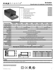
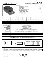
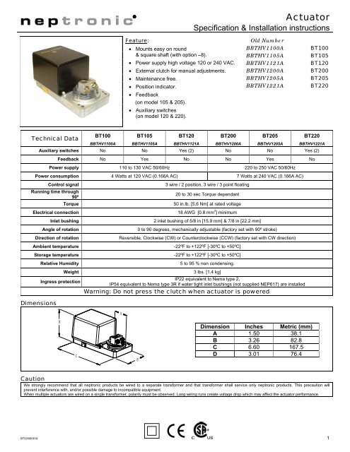
<strong>Actuator</strong>Specification & Installation instructionsFeature:• Mounts easy on round& square shaft (with option –8).• Power supply high voltage 120 or 240 VAC.• External clutch for manual adjustments.• Maintenance free.• Position indicator.• Feedback(on model 105 & 205).• Auxiliary switches(on model 120 & 220).Old NumberBBTHV1100ABBTHV1105ABBTHV1121ABBTHV1200ABBTHV1205ABBTHV1221ABT100BT105BT120BT200BT205BT220Technical DataBT100 BT105 BT120 BT200 BT205 BT220BBTHV1100A BBTHV1105A BBTHV1121A BBTHV1200A BBTHV1205A BBTHV1221AAuxiliary switches No No Yes (2) No No Yes (2)Feedback No Yes No No Yes NoPower supply 110 to 130 VAC 50/60Hz 220 to 250 VAC 50/60HzPower consumption 4 Watts at 120 VAC (0.166A AC) 7 Watts at 240 VAC (0.166A AC)Control signalRunning time through90ºTorqueElectrical connectionInlet bushingAngle of rotationDirection of rotationAmbient temperatureStorage temperatureRelative Humidity3 wire / 2 position, 3 wire / 3 point floating20 to 30 sec Torque dependant50 in.lb. [5,6 Nm] at rated voltage18 AWG [0.8 mm 2 ] minimum2 inlet bushing of 5/8 in [15.9 mm] & 7/8 in [22.2 mm]0 to 90 degrees, mechanically adjustable (factory set with 90º stroke)Reversible, Clockwise (CW) or Counterclockwise (CCW) (factory set with CW direction)-22ºF to +122ºF [-30ºC to +50ºC]-22ºF to +122ºF [-30ºC to +50ºC]5 to 95 % non condensing.DimensionsWeightIngress protection3 lbs. [1.4 kg]IP22 equivalent to Nema type 2,IP54 equivalent to Nema type 3R if water tight inlet bushings (not supplied NEP617) are installedWarning: Do not press the clutch when actuator is poweredADCBDimension Inches Metric (mm)A 1.50 38.1B 3.26 82.8C 6.60 167.5D 3.01 76.4CautionWe strongly recommend that all neptronic products be wired to a separate transformer and that transformer shall service only neptronic products. This precaution willprevent interference with, and/or possible damage to incompatible equipment.When multiple actuators are wired on a single transformer, polarity must be observed. Long wiring runs create voltage drop which may affect the actuator performance.BT00/080619 1
BT100/105/120/200/205/220Specification & Installation instructionMechanical installationMOUNTINGBRACKETCLUTCH1. Manually close the damper blades and positioned theactuator at 0º or 90º.2. Slide the actuator onto the shaft.3. Tighten the nuts on the “U” bolt to the shaft with a 8mmwrench to a torque of 60 in.lb. [6,7 Nm].4. Slide the mounting bracket under the actuator. Ensure freemovement of the slot at the base of the actuator. Thebracket pin must be placed in the mid distance of the slot.5. Fix the bracket to the ductwork with #8 self-tapping screws.Wiring DiagramsCaution: Risk of electric shock. Remove power prior to connect.3 wire / 2 position (ON-OFF)1 2 3NEUTRAL (-)LINE (+)DRIVE CW3 wire / 3 point floating1 2 3NEUTRAL (-)LINE (+)DRIVE CWDRIVE CCWPC BoardBBTHV1X00APotentiometerOnly on model 105 & 205Rotation directionCCW(90 to 0º)CW(0 to 90º)TerminalJP1 1 2 3JP2Rotationdirection6 7 8Feedback or switches terminalOnly on model 105, 120, 205 & 220Stroke adjustmentTo adjust the stroke, move the adjustment screws at the desired position.2