TRO24T4XYZ1 - Neptronic
TRO24T4XYZ1 - Neptronic
TRO24T4XYZ1 - Neptronic

You also want an ePaper? Increase the reach of your titles
YUMPU automatically turns print PDFs into web optimized ePapers that Google loves.
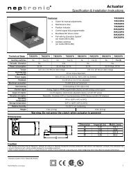
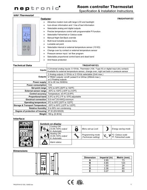
ºF / º CVAV ThermostatFeatures: Attractive modern look with large LCD and backlight Icon-driven information and 1 line of text information Selectable analog and digital outputs Precise temperature control with programmable PI function Selectable Fahrenheit or Celsius scale Manual Night Set Back override Multi level lockable access menu Lockable set point Selectable internal or external temperature sensor (10 KΩ) Change over by contact or external temperature sensor Pressure sensor input / air flow program Selectable proportional control band and dead band Anti-freeze protectionRoom controller ThermostatSpecification & Installation Instructions<strong>TRO24T4XYZ1</strong>Technical Data<strong>TRO24T4XYZ1</strong>3 Universal analog inputs: 0-10Vdc, Thermistor (10k / Type III) or digital input (dry contact)InputsAvailable for external temperature sensor, change over, night set back or pressure sensor2 Analog outputs: 0-10Vdc or 2-10Vdc selectable (2mA max.)Outputs 4 TRIAC outputs: on/off, pulsed 0 or 24Vac (250mA max.),or 2 Floating outputsPower supply 22 to 26 Vac 50/60HzPower consumption 1VASet point range 10ºC to 40ºC [50ºF to 104ºF]External sensor range -40ºC to 100ºC [-40ºF to 212ºF]Control accuracy Temperature: ±0.4ºC [0.8ºF]Proportional band 0.5ºC to 5ºC [1ºF to 10ºF] adjustableElectrical connection 0.8 mm 2 [18 AWG] minimumOperating temperature 0ºC to 50ºC [32ºF to 122ºF]Storage & Transport Temperature -30ºC to 50ºC [-22ºF to 122ºF]Relative Humidity 5 to 95% non condensingDegree of protection of housing IP 30 (EN 60529)Weight 160 g. [0.36 lb]Interface..AM PM..MO TU WE TH FR SA SU%RHCFSymbols on displayCooling ON33,66,100% outputA: AutomaticHeating ON33,66,100% outputA: AutomaticMenu set-up LockProgramming mode(Technician setting)C orFEnergy saving modeºC: Celsius scaleºF: Fahrenheit scaleAlarm statusDimensionsBEDDimension Imperial (in) Metric (mm)A 2.85 73B 4.85 123C 1.00 24D 2.36 60E 3.27 83AC<strong>TRO24T4XYZ1</strong>-ESL-120925.doc 1
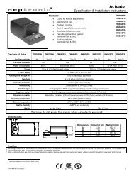
<strong>TRO24T4XYZ1</strong>Specification & Installation InstructionsMounting InstructionsABCDECAUTION: Risk of malfunction. Remove power prior to separate thermostat cover from its base.A. Remove the screw (captive) holding the base and the front cover of the thermostat.B. Lift the front cover of the thermostat to separate it from the base.C. Pull wire through the base hole.D. Secure the base to the wall using wall anchors and screws (supplied). Make the appropriate connections.E. Mount the control module on the base and secure using the screw.Terminal DescriptionTerminals Description1 Common2 Common3 Common4 24Vac5 24Vac6 Triac output 1 (TO1) TO1 close7 Triac (24Vac EXT.) (TO1 & TO2) see Settings section8 Triac output 2 (TO2) TO2 openTB19 Triac output 3 (TO3) TO3 closeIf set in floating,terminals 6-8(floating 1),terminals 9-11(floating 2) are asfollow:10 Triac (24Vac EXT.) (TO3 & TO4) see Settings section11 Triac output 4 (TO4) TO4 open12 Analog input 1 (AI1)13 Analog input 2 (AI2)14 Analog input 3 (AI3)15 Analog output 1 (AO1)16 Analog output 2 (AO2)12FLOATINGSettings on PC BoardDS11 2 31 2 3 4 5 6ONONDS2JP124VACModeSelectorJP2Connectingstrip TB1Analog inputDip switch24VACTemperature sensorTB11 2 3 4 5 6 7 8 9 10 11 12 13 14 15 16 17 18Mode Selection Dip Switch (DS1)ON1 2 3OFF: operation mode,ON: programming modeNot usedNot usedAnalog Input Dip Switch (DS2)ON1 2 3 4 5 6AI1AI2AI3AI1AI2AI3Triac (digital) Output Signal Selection(JP1 for TO3 & TO4 - JP2 for TO1 & TO2)24VAC24VAC EXT.Jumper on left: All triac output signal islinked to internal 24Vac.(Same 24Vac than thermostat)Jumper on right: All triac output signal islinked to external 24Vac.(Different 24Vac than thermostat)ONOFFThermistor 10KΩDry contactDS2.1 DS2.20-10 Vdc DS2.2 DS2.1Thermistor 10KΩDry contactDS2.3 DS2.40-10 Vdc DS2.4 DS2.3Thermistor 10KΩDry contactDS2.5 DS2.60-10 Vdc DS2.6 DS2.52
<strong>TRO24T4XYZ1</strong>Specification & Installation InstructionsProgramming ModeWhen in this mode this symbol is displayed. Please press on button to advance to the next program function, press on buttonºF / º Cto return to preceding stage and press on button or to change value. You can leave the programming mode at any time,changed values will be recorded.Step Display Description ValuesInternal temperature sensor Calibration:Display shows “inside temper sensor offset” and temperature read byinternal temperature sensor.Range :1CYou can adjust the calibration of the sensor by comparison with a known 10 to 40ºC [50 to 104ºF]thermometer. For example if thermostat has been installed in an area (max. offset ± 5 ºC)where temperature is slightly different than the room typical temperature Increment: 0.1ºC [0.2ºF](thermostat place right under the air diffuser).2 CMinimum set point:Display shows “adjust minimum user setpnt” and the minimum set pointtemperature.Please select the desired minimum set point temperature.The minimum value is restricted by the maximum value. (step #3)Minimum range:10 to 40ºC [50 to 104ºF]Increment: 0.5ºC [1ºF]Default value: 15ºC [59ºF]3 CMaximum set point:Display shows “adjust maximum user setpnt” and the maximum set pointtemperature.Please select the desired maximum set point temperature.The maximum value is restricted by the minimum value. (step #2)Maximum range:10 to 40ºC [50 to 104ºF]Increment: 0.5ºC [1ºF]Default value: 30ºC [86ºF]4Locking the set point:Display shows “user setpnt locked” and the status of the function.You can lock or unlock the set point adjustment by end user. If locked,“yes” and lock symbol will appear.Default value: Unlocked5C6Adjust internal set point:Display shows “adjust intern setpnt” and the set point temperature.Select the desired set point temperature; this one should be within thetemperature range.Lock symbol will appear if the set point was locked at the previous step.Set point value is restricted by the minimum and maximum value. (step#2 & 3)Adjust the control mode:Display shows “adjust temper control mode”. Cooling and heatingsymbols are also displayed.Select which control mode you want to authorize:Automatic cooling and heating, cooling or heating, heating only or coolingonly.Set point range:10 to 40ºC [50 to 104ºF]Increment: 0.5ºC [1ºF]Default value: 22ºC [72ºF]7If you want to authorize this entire mode, choose Automatic mode.Set On/Off function enable or disable:Display shows “enable on off control mode”.You can enable or disable the On/Off function in control modeadjustment by end user.Default value:Automatic cooling and heatingDefault value:Enable (YES)8Set TO1 output signal:Display shows “select TO1 output signal”.Select which signal output you want for TO1 output.You can choose on/off, pulse or floating signal output.If you select floating, TO1 will be set close and TO2 open.Default value: floating3
<strong>TRO24T4XYZ1</strong>Specification & Installation InstructionsStep Display Description ValuesSet TO1 signal ramp:Display shows “select TO1 ramp”.Select which ramp you want for TO1.You can choose:Changeover ramp,Heating ramp 1,Heating ramp 2,Cooling ramp 1,Cooling ramp 2,9OFFNote: If “FLT” (floating) has been selected at step #8, the same ramp willbe used for TO2.If “PULs” has been selected at step #8, you can only choose Heatingramp 1 or Heating ramp 2.10If you selected on/off signal at step #8, go directly to step #12.If you selected pulse signal at step #8 or OFF here, go directly tostep #13.Set floating time: (If “FLT” has been selected at step #8)Display shows “set floating time in seconds” and the floating time value(in seconds).Please select desired value of the floating time signal.Default value: Cr1 (Cooling ramp1)Range: 15 to 250 sec.Increment: 5 sec.Default value: 100 sec.111213Set motor direction:Display shows “select motor direct reverse”.Select which direction you want for the motor.You can choose:Direct “clockwise” (0 to 90º) orReverse “counter clockwise” (90 to 0º)Go to step #16.Set TO1 on-off close position: (If “OnOf” has been selected at step #8)Display shows “select TO1 close percent” and the value of the closeposition of the TO1 output.Please select at which percentage you want TO1 to close: at 20%, 40%,60% or 80% of the demand of the ramp that you selected at step # 9.Contact will automatically open at 0% of the demand.Set TO2 output signal:Display shows “select TO2 output signal”.Select which signal output you want for TO2 output.You can choose on/off or pulse signal output.Default value: direct (dir)Range: 20, 40, 60, 80Increment: 20 %Default value: 40 (40% of the demand)Default value: on-off14Set TO2 signal ramp:Display shows “select TO2 ramp”.Select which ramp you want for TO2.You can choose:Changeover ramp,Heating ramp 1,Heating ramp 2,Cooling ramp 1,Cooling ramp 2,OFFIf “PULs” has been selected at step #13, you can only choose Heatingramp 1 or Heating ramp 2.If you selected pulse signal at step #13 or OFF here, go directly tostep #16.Default value: Cr1 (Cooling ramp1)4
<strong>TRO24T4XYZ1</strong>Specification & Installation InstructionsStep Display Description ValuesSet TO2 on-off close position: (If “OnOf” has been selected at step #13)Display shows “select TO2 close percent” and the value of the close15position of the TO2 output.Range: 20, 40, 60, 80Please select at which percentage you want TO2 to close: at 20%, 40%,Increment: 20 %60% or 80% of the demand of the ramp that you selected at step # 14.Default value: 40 (40% of the demand)Contact will automatically open at 0% of the demand.16Set TO3 output signal:Display shows “select TO3 output signal”.Select which signal output you want for TO3 output.You can choose on/off, pulse or floating signal output.If you select floating, TO3 will be set close and TO4 open.1718Set TO3 signal ramp:Display shows “select TO3 ramp”.Select which ramp you want for TO3.You can choose:Changeover ramp,Heating ramp 1,Heating ramp 2,Cooling ramp 1,Cooling ramp 2,OFFNote: If “FLT” (floating) has been selected at step #16, the same rampwill be used for TO4.If “PULs” has been selected at step #16, you can only choose Heatingramp 1 or Heating ramp 2.If you selected on/off signal at step #16, go directly to step #20.If you selected pulse signal at step #16 or OFF here, go directly tostep #21.Set floating time: (If “FLT” has been selected at step #16)Display shows “set floating time in seconds” and the floating time value(in seconds).Please select desired value of the floating time signal.Default value: on-offDefault value: Hr1 (Heating ramp 1)Range: 15 to 250 sec.Increment: 5 sec.Default value: 100 sec.192021Set motor direction:Display shows “select motor direct reverse”.Select which direction you want for the motor.You can choose:Direct “clockwise” (0 to 90º) orReverse “counter clockwise” (90 to 0º)Go to step #24Set TO3 on-off close position: (If “OnOf” has been selected at step #16)Display shows “select TO3 close percent” and the value of the closeposition of the TO3 output.Please select at which percentage you want TO3 to close: at 20%, 40%,60% or 80% of the demand of the ramp that you selected at step # 17.Contact will automatically open at 0% of the demand.Set TO4 output signal:Display shows “select TO4 output signal”.Select which signal output you want for TO4 output.You can choose on/off or pulse signal output.Default value: direct (dir)Range: 20, 40, 60, 80Increment: 20 %Default value: 40 (40% of the demand)Default value: on-off5
<strong>TRO24T4XYZ1</strong>Specification & Installation InstructionsStep Display Description ValuesSet TO4 signal ramp:Display shows “select TO4 ramp”.Select which ramp you want for TO4.You can choose:Changeover ramp,Heating ramp 1,Heating ramp 2,Cooling ramp 1,22Cooling ramp 2,OFFIf “PULs” has been selected at step #21, you can only choose Heatingramp 1 or Heating ramp 2.2324If you selected pulse signal at step #21 or OFF here, go directly tostep #24.Set TO4 on-off close position: (If “OnOf” has been selected at step #21)Display shows “select TO4 close percent” and the value of the closeposition of the TO4 output.Please select at which percentage you want TO4 to close: at 20%, 40%,60% or 80% of the demand of the ramp that you selected at step # 22.Contact will automatically open at 0% of the demand.Set AO1 analog signal ramp:Display shows “select AO1 analog ramp”.Select which ramp you want for analog signal on AO1.You can choose:Changeover ramp,Heating ramp 1,Heating ramp 2,Cooling ramp 1,Cooling ramp 2,OFFDefault value: Hr2 (Heating ramp 2)Range: 20, 40, 60, 80Increment: 20 %Default value: 40 (40% of the demand)25Set AO2 analog signal ramp:Display shows “select AO2 analog ramp”.Select which ramp you want for analog signal on AO2.You can choose:Changeover ramp,Heating ramp 1,Heating ramp 2,Cooling ramp 1,Cooling ramp 2,OFFIf “OFF” was selected for AO1, go to step #29.If “OFF” is selected for AO1 & AO2, go to step #32.Default value: Cr1 (Cooling ramp1)26Minimum voltage of AO1 output: (Only if “OFF” hasn’t been selected at step #24)Display shows “min vdc analog ao1 output” and the value of the minimumvoltage of the AO1 output.Please select the desired value of the minimum voltage of AO1 output.(This is the “zero” value)The minimum value is restricted by the maximum value. (step #27)Default value: Hr1 (Heating ramp 1)Range: 0.0 to 10.0 VoltIncrement: 0.1 VoltDefault value: 0.0 Volt6
<strong>TRO24T4XYZ1</strong>Specification & Installation InstructionsStep Display Description Values33Set AI2 input signal:Display shows “select AI2 input signal”.Select which signal you want for AI2 input.You can choose:(Same as AI1 see step #32)Default value: OFF3435 CNote: AI1 input signal has priority to AI2, if you have selected the samefunction AI2 will not be functional.Set AI3 input signal:Display shows “select AI3 input signal”.Select which signal you want for AI3 input.You can choose:(Same as AI1 see step #32)Note: AI1 & AI2 input signal have priority to AI3, if you have selected thesame function AI3 will not be functional.External temperature sensor Calibration: (If ‘’EtS’’ has been selected at step#32, 33 or 34)Display shows “extern temper sensor offset” and the temperature readby the external temperature sensor (if connected on the selected input).If the sensor is not connected or short circuited, the display shows“Eror”. You can adjust the calibration of the external sensor bycomparison with a known thermometer.Default value: OFFRange:0 to 50ºC [41 to 122.0ºF](max. offset ± 5 ºC)Increment: 0.1ºC [0.2ºF]36 C37Change over set point temperature: (If ‘’SENs’’ has been selected at step #32, 33or 34)Display shows “Ch over setpnt temper” and the change over set pointtemperature.Range: 10 to 40ºC [50 to 104ºF]Please select the change over set point temperature.Increment: 0.5ºC [1ºF]Note: heating mode will be activated when temperature read by external Default value: 24ºC [82ºF]sensor is above the change over set point temperature, and cooling modewill be activated when temperature read by external sensor is under.Night set back derogation time :(If ‘’nSb’’ has been selected at step #32, 33 or 34)Display shows “nsb delay override minutes” and the derogation time inminute. NSB symbol is also displayed.Please select the desired derogation time, if no derogation time isdesired select “0”.Range: 0 to 180 min.Increment: 15 min.Default value: 120 min.38 C39C40Heating Set point during Night set back: (If ‘’nSb’’ has been selected at step#32, 33 or 34)Display shows “night setback heating setpnt” and the value of theheating set point temperature during night set back. NSB and heatingsymbols are also displayed.Please select the heating set point temperature during night set back.The maximum value is restricted by the no occupancy cooling set point.(step # 39)Cooling Set point during Night set back: (If ‘’nSb’’ has been selected at step#32, 33 or 34)Display shows “night setback cooling setpnt” and the value of thecooling set point temperature during night set back. NSB and coolingsymbols are also displayed.Please select the cooling set point temperature during night set back.The minimum value is restricted by the no occupancy heating set point.(step # 38)Set output signal used for pressure independent: (If ‘’PrSd’’ or ‘’PrSa’’ hasbeen selected at step #32, 33 or 34)Display shows “pressur indepen output”.Select which signal output is affected by pressure (connected toactuator).You can choose Floating 1 (TO1 & TO2), Floating 2 (TO3 & TO4),Analog 1 (AO1) or Analog 2 (AO2).Range: 10.0 to 40.0ºC [50 to 104ºF]Increment: 0.5ºC [1ºF]Default value: 16.0ºC [61ºF]Range: 10.0 to 40.0ºC [50 to 104ºF]Increment: 0.5ºC [1ºF]Default value: 28.0ºC [82ºF]Note: These selections can vary according to the choice made on steps#8 & #16. Default value: floating 18
<strong>TRO24T4XYZ1</strong>Specification & Installation InstructionsStep Display Description ValuesDead band in cooling ramp2:Display shows “control dead band 2 cooling” and the value of thecooling ramp2 dead band, cooling symbol is also displayed.Dead band range :50CPlease select the desired value of cooling ramp2 dead band.0.0 to 5.0ºC [0.0 to 10.0ºF]Increment: 0.1ºC [0.2ºF]Default value: 0.3ºC [0.6ºF]51Anti-cycling delay cooling contact (protection for compressor):Display shows “cooling anti cycle minutes” and the value (in minutes) ofthe delay to activate / reactivate cooling contact.Please select the desired value of the delay cooling contact.Range: 0 to 15 min.Increment: 1 min.Default value: 2 min.52Integration time factor setting:Display shows “adjust intgral time in seconds” and the time in secondsfor the integration factor compensation.Please select the desired value of the integration factor compensation.Range: 0 to 250 secondsIncrement: 5 secondsDefault value: 0 seconds53Enable or disable anti-freeze protection:Display shows “enable anti freeze protect”.You can enable or disable the Anti-freeze function.When enabled, if temperature drop to 4ºC [39ºF], heat will start even ifthermostat is in OFF mode.Heat will stop when temperature reach 5ºC [41ºF].Default value:Disable (NO)Air Flow Program Mode (Available when in Operation Mode; DS1-1 OFF position)Push on both and ºF / º C buttons for 5 seconds to access the user air flow program mode. This menu is accessible only If ‘’PrSd’’ or‘’PrSA’’ has been selected at step #32, 33 or 34.Step Display Description ValuesF1Password:Display shows “enter passwrd” and 000.You have 1 minute to enter the password by incrementing ordecrementing the blinking digit with and buttons.To modifyfollowing digit on right press , to return to digit on the left press ºF / º C .Password: 637 (corresponding to NEP)When the password is entered press on . If you do a mistake, youwill see “Eror” and the thermostat will return in operation mode. Youneed to redo this step.When the password is entered and you are in the balancing mode, this symbol is displayed. Press on the button to advanceto the next program function, press on the ºF / º C button to return to previous step and press on the or button to change value.The system will exit the menus and return to normal function if you navigate through the entire menu or if no button is pressed for 5minutes, changed values will be saved.Step Display Description ValuesInternal temperature sensor calibration:Display shows “inside temper sensor offset” and temperature read byF2internal temperature sensor.Range : 10 to 40ºC [50 to 104ºF]You can adjust the calibration of the sensor by comparison with a known(max. offset ± 5 ºC)thermometer. For example if thermostat has been installed in an areaIncrement: 0.1ºC [0.2ºF]where temperature is slightly different than the room typical temperatureC(thermostat place right under the air diffuser).F3CExternal temperature sensor calibration: (If ‘’EtS’’ has been selected at step#32, 33 or 34 of programming mode)Display shows “extern temper sensor offset” and the temperature readby the external temperature sensor (if connected on the selected input).If the sensor is not connected or short circuited, the display shows“Eror”. You can adjust the calibration of the external sensor bycomparison with a known thermometer.Range: 0 to 50ºC [41 to 122.0ºF](max. offset ± 5 ºC)Increment: 0.1ºC [0.2ºF]10
<strong>TRO24T4XYZ1</strong>F12F13Minimum airflow calibration:Display shows “minimum airflow” and the value of the minimum airflowdetected by the pressure sensor.The thermostat will send a signal to the actuator close the VAV boxe atminimum airflow. When the value on thermostat is stable, you can adjustthe calibration of the sensor by comparison with the reading on amanometer or a balometer.If you can’t stabilize the system, you will need to increase the filter value.(step #F4)Maximum airflow calibration:Display shows “maximum airflow” and the value of the maximum airflowdetected by the pressure sensor.The thermostat will send a signal to the actuator open the VAV boxe atmaximum airflow. When the value on thermostat is stable, you can adjustthe calibration of the sensor by comparison with the reading on amanometer or a balometer.If you can’t stabilize the system, you will need to increase the filter value.(step #F4)Come back to step #F11Specification & Installation InstructionsRange:0 to k factor or V nominal(max. offset ± ½ value)Increment: 1Range:0 to k factor or V nominal(max. offset ± ½ value)Increment: 1Operation ModeStep Description DisplayAAt powering up, thermostat will light display and activate all LCD segmentsduring 2 seconds.Illuminating the LCD.To illuminate the LCD, you just have to push onto any of the 4 buttons. LCDwill light for 4 seconds.Temperature displayIn operation mode, thermostat will automatically display temperature read.If “OFF”, “- - -” and alarm symbol are displayed, the temperature sensor isCnot connected or short circuited.To change the scale between ºC and ºF, press on ºF / º Cbutton.Air flow displayTo display the air flow, press on button for 5 seconds. When in thismode “airflow” is displayed. Air flow value will be displayed during 5seconds.BSet point display and adjustmentTo display the set point, press two times on or . Set point will bedisplayed during 3 seconds.To adjust set point, press on or while the temperature set point isdisplayed.CNote: If set point adjustment has been locked, symbol will be displayed.CCDNight set back (NSB) :When thermostat is in night set back mode, NSB symbol is displayed, soset point for cooling and/or heating are increased as per the setting made inprogramming mode.If not locked, night set back can be derogated for a predetermined period bypressing onto any of the 4 buttons. During period of NSB derogation thesymbol will flash. If NSB does not flash, the derogation period is finished orthe Night set back derogation has been locked in programming mode.Control mode selection :To verify which control mode is set, press on button. Control mode willbe displayed during 5 seconds.To change of control mode, press on the button while control mode isdisplayed. You can choose one of the following: Automatic Cooling or Heating Cooling and Heating OFF Cooling only Heating onlyNote: These selections can vary according to the choice made on steps #6& #7.CRecycling at end of lifeAt end of life, please return the thermostat to your <strong>Neptronic</strong> ® local distributor for recycling. If you need to find the nearest <strong>Neptronic</strong> ®authorized distributor, please consult www.neptronic.com.12