ADSS Cable - Draka Communications
ADSS Cable - Draka Communications
ADSS Cable - Draka Communications

Create successful ePaper yourself
Turn your PDF publications into a flip-book with our unique Google optimized e-Paper software.
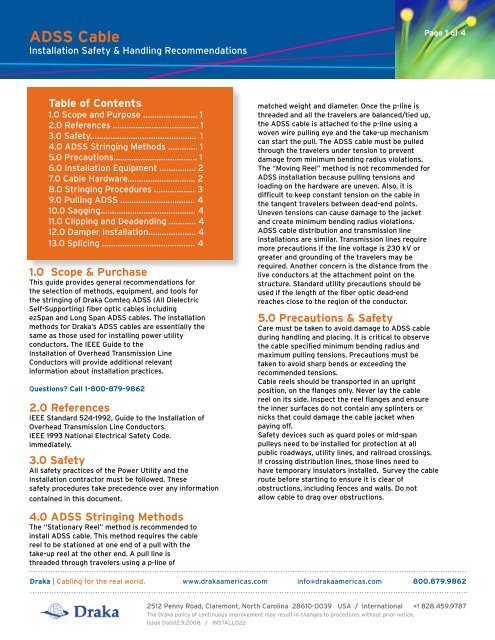
<strong>ADSS</strong> <strong>Cable</strong><br />
Installation Safety & Handling Recommendations<br />
Table of Contents<br />
1.0 Scope and Purpose ........................ 1<br />
2.0 References ...................................... 1<br />
3.0 Safety............................................... 1<br />
4.0 <strong>ADSS</strong> Stringing Methods ............. 1<br />
5.0 Precautions..................................... 1<br />
6.0 Installation Equipment ................ 2<br />
7.0 <strong>Cable</strong> Hardware.............................. 2<br />
8.0 Stringing Procedures .................. 3<br />
9.0 Pulling <strong>ADSS</strong> ................................. 4<br />
10.0 Sagging.......................................... 4<br />
11.0 Clipping and Deadending ............ 4<br />
12.0 Damper Installation..................... 4<br />
13.0 Splicing ......................................... 4<br />
1.0 Scope & Purchase<br />
This guide provides general recommendations for<br />
the selection of methods, equipment, and tools for<br />
the stringing of <strong>Draka</strong> Comteq <strong>ADSS</strong> (All Dielectric<br />
Self-Supporting) fiber optic cables including<br />
ezSpan and Long Span <strong>ADSS</strong> cables. The installation<br />
methods for <strong>Draka</strong>’s <strong>ADSS</strong> cables are essentially the<br />
same as those used for installing power utility<br />
conductors. The IEEE Guide to the<br />
Installation of Overhead Transmission Line<br />
Conductors will provide additional relevant<br />
information about installation practices.<br />
Questions? Call 1-800-879-9862<br />
2.0 References<br />
IEEE Standard 524-1992, Guide to the Installation of<br />
Overhead Transmission Line Conductors.<br />
IEEE 1993 National Electrical Safety Code.<br />
immediately.<br />
3.0 Safety<br />
All safety practices of the Power Utility and the<br />
Installation contractor must be followed. These<br />
safety procedures take precedence over any information<br />
contained in this document.<br />
4.0 <strong>ADSS</strong> Stringing Methods<br />
The “Stationary Reel” method is recommended to<br />
install <strong>ADSS</strong> cable. This method requires the cable<br />
reel to be stationed at one end of a pull with the<br />
take-up reel at the other end. A pull line is<br />
threaded through travelers using a p-line of<br />
matched weight and diameter. Once the p-line is<br />
threaded and all the travelers are balanced/tied up,<br />
the <strong>ADSS</strong> cable is attached to the p-line using a<br />
woven wire pulling eye and the take-up mechanism<br />
can start the pull. The <strong>ADSS</strong> cable must be pulled<br />
through the travelers under tension to prevent<br />
damage from minimum bending radius violations.<br />
The “Moving Reel” method is not recommended for<br />
<strong>ADSS</strong> installation because pulling tensions and<br />
loading on the hardware are uneven. Also, it is<br />
difficult to keep constant tension on the cable in<br />
the tangent travelers between dead-end points.<br />
Uneven tensions can cause damage to the jacket<br />
and create minimum bending radius violations.<br />
<strong>ADSS</strong> cable distribution and transmission line<br />
installations are similar. Transmission lines require<br />
more precautions if the line voltage is 230 kV or<br />
greater and grounding of the travelers may be<br />
required. Another concern is the distance from the<br />
live conductors at the attachment point on the<br />
structure. Standard utility precautions should be<br />
used if the length of the fiber optic dead-end<br />
reaches close to the region of the conductor.<br />
5.0 Precautions & Safety<br />
Care must be taken to avoid damage to <strong>ADSS</strong> cable<br />
during handling and placing. It is critical to observe<br />
the cable specified minimum bending radius and<br />
maximum pulling tensions. Precautions must be<br />
taken to avoid sharp bends or exceeding the<br />
recommended tensions.<br />
<strong>Cable</strong> reels should be transported in an upright<br />
position, on the flanges only. Never lay the cable<br />
reel on its side. Inspect the reel flanges and ensure<br />
the inner surfaces do not contain any splinters or<br />
nicks that could damage the cable jacket when<br />
paying off.<br />
Safety devices such as guard poles or mid-span<br />
pulleys need to be installed for protection at all<br />
public roadways, utility lines, and railroad crossings.<br />
If crossing distribution lines, those lines need to<br />
have temporary insulators installed. Survey the cable<br />
route before starting to ensure it is clear of<br />
obstructions, including fences and walls. Do not<br />
allow cable to drag over obstructions.<br />
Page 1 of 4<br />
<strong>Draka</strong> | Cabling for the real world. www.drakaamericas.com info@drakaamericas.com 800.879.9862<br />
2512 Penny Road, Claremont, North Carolina 28610-0039 USA / International +1 828.459.9787<br />
The <strong>Draka</strong> policy of continuous improvement may result in changes to procedures without prior notice.<br />
Issue Date12.9.2008 / INSTALL022
<strong>ADSS</strong> <strong>Cable</strong><br />
Installation Safety & Handling Recommendations<br />
6.0 Installation Equipment<br />
Grips and Pulling Eyes: Chinese finger type pulling<br />
eyes are recommended to attach the cable to the<br />
pulling line.<br />
Travelers (Sheaves, Pulleys): The travelers must have<br />
a soft neoprene or similar material liner to cushion the<br />
cable from the bare metal of the traveler. The liner or<br />
insert must be smooth and show no signs of wear and<br />
tear. It is unacceptable for a traveler to have sections<br />
of cushion missing or worn through at the bottom of<br />
the groove.<br />
damage to the ripcords, armor, buffer tubes, and fibers.<br />
7.0 <strong>Cable</strong> Hardware<br />
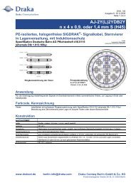
7.1 Fiber Optic Tangent<br />
Fiber Optic Tangent: Used as cable suspension<br />
hardware only on spans less than 350 feet when<br />
the angle of change, either horizontal or vertical,<br />
is less than 15°. The tangent clamp is designed to<br />
hold the cable in the air at the pole without<br />
gripping the cable as with a suspension (described<br />
below). The tangent is designed to allow the cable<br />
to slip through the unit at a tension imbalance<br />
greater than 400 pounds. There are several<br />
different approved suppliers of the tangent<br />
hardware, each with different designs. Please<br />
refer to <strong>Draka</strong> for recommendations of the<br />
advantages/disadvantages of each for your<br />
applications.<br />
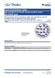
7.2 Armor Grip Suspension (AGS)<br />
Armor Grip Suspension (AGS): Used for any span<br />
length with an angle change, either horizontal or<br />
vertical, less than 30°. An AGS Suspension shall be<br />
used for in-line structures if the span is greater<br />
than 350 feet.<br />
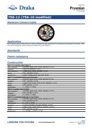
7.3 Fiber Optic Dead-ends<br />
Fiber Optic Dead-ends: Used in several instances.<br />
A dead-end is installed at each end of the cable<br />
length to attach to the structures. Two deadends<br />
are used at angle changes of 30° or greater, either<br />
horizontal or vertical. If the structures are in-line<br />
but have a vertical difference greater than 20°,<br />
deadends shall be used to distribute the cable<br />
through the incline/decline.<br />
Pulling Rope: The pulling rope must be well matched<br />
to the cable diameter and cable weight. This will<br />
better prepare the travelers in the system to balance<br />
the load as the cable is pulled and allow the cable to<br />
ride in the bottom of the traveler groove.<br />
Tensioner: A bull wheel tensioner with a brake is<br />
recommended for an <strong>ADSS</strong> installation.<br />
Puller with sufficient pull rope capacity: The puller<br />
should be equipped with a brake to keep constant<br />
tension of the cable as it is being installed.<br />
Figure 1. Fiber Optic Tangent<br />
Figure 2. AGS Suspension<br />
Figure 3. Fiber Optic Deadend<br />
Page 2 of 4
<strong>ADSS</strong> <strong>Cable</strong><br />
Installation Safety & Handling Recommendations<br />
8.0 Typical Stringing Operations<br />
Procedures<br />
8.0 Installation Equipment Sites<br />
Installation Equipment Sites: It is important to<br />
pick proper locations for the pay-off and take-up<br />
equipment. The <strong>ADSS</strong> cable reel (pay-off) must be<br />
located directly in line with the first traveler and<br />
must be back from the structure four times the<br />
height of the traveler (4:1 distance to height<br />
ratio). It is recommended to have at least three<br />
structures before the first large angle change. The<br />
equipment and <strong>ADSS</strong> cable reel should be in a safe<br />
and secure location, worry-free from vandalism or<br />
theft since the equipment could sit overnight.<br />
8.1 Traveler Installation<br />
Traveler Installation: Each structure in the pulling<br />
segment must have a traveler installed and a<br />
pulling rope threaded (reeved) through it. Each<br />
traveler must be balanced so that the rope, and<br />
the following <strong>ADSS</strong> cable, ride at the bottom of<br />
the neoprene insert’s groove. It is important to tie<br />
up the traveler at each angle so the pulling rope<br />
and <strong>ADSS</strong> cable enter and exit the traveler<br />
smoothly (See Figures 4 and 5 at right). If the<br />
cable enters at an angle, it increases the chance of<br />
jumping from the traveler groove into space<br />
between the traveler and the yoke holding the<br />
traveler to the pole. This would cause severe<br />
damage to the cable.<br />
8.3 Pulling Lines<br />
Pulling Lines: Once the travelers are installed,<br />
the pulling rope shall be threaded (reeved) through<br />
the system. It is extremely important that the<br />
pulling rope and the <strong>ADSS</strong> cable have the same<br />
diameter and approximate weight. This will allow<br />
the travelers to float at the same level with the<br />
pulling rope as they will when the <strong>ADSS</strong> cable<br />
enters the travelers. The pulling line should be all<br />
dielectric and not susceptible to internal,<br />
electrical static charge build up. The pulling rope<br />
should never be allowed to drape over distribution<br />
lines or slump between pole attachments. It<br />
should have constant tension throughout the<br />
operation.<br />
Figure 4. Incorrect Traveler<br />
Tie up Rope<br />
<strong>Cable</strong><br />
<strong>Cable</strong><br />
Figure 5. Correct tie up of Traveler<br />
Page 3 of 4
<strong>ADSS</strong> <strong>Cable</strong><br />
Installation Safety & Handling Recommendations<br />
9.0 Pulling <strong>ADSS</strong><br />
The <strong>ADSS</strong> cable shall be attached to the pulling rope<br />
using a double swivel eye and woven wire grip. The<br />
double swivel eye insures the <strong>ADSS</strong> cable will not<br />
see induced torque as the pulling line enters and<br />
exits each traveler. A “flag” shall be attached just<br />
behind the swivel eye on the <strong>ADSS</strong> cable jacket.<br />
This flag should stay straight through each traveler.<br />
If the flag starts to flip over the cable, it shows the<br />
swivel eye is not working properly and the pulling<br />
operation should be stopped and oil or fix the<br />
swivel. The woven wire grip shall be of sufficient<br />
length on the cable jacket to insure even loading of<br />
the cable strength members. The edges of the<br />
woven wire grip should be taped smooth so the grip<br />
does not damage the neoprene inserts<br />
10.0 Sagging<br />
The <strong>ADSS</strong> cable shall be sagged from the pay-off<br />
(cable reel) end and work back toward the take-up<br />
equipment starting with the deadend at the first<br />
structure near the cable reel. The sag can be<br />
adjusted using several methods. The recommended<br />
method is the ‘line of site’ method. This requires<br />
the sag distance to be determined ahead of time for<br />
each particular span length. One or more spans<br />
between deadend locations should be checked using<br />
this method.<br />
“Line of Sight” sagging method requires climbing<br />
both structures on either side of a span to be<br />
checked. The structure closest to the pay-off end<br />
of the system is deadended. Then the next<br />
structure is marked using bright colored tape with<br />
the appropriate mid-span distance from the<br />
attachment height. The lineman returns to the payoff<br />
end structure and measures down the mid-span<br />
sag distance and places his line of site at that same<br />
height. This person should have radio contact with<br />
the take-up operator and give instructions of how<br />
much to tighten the cable in the system so that the<br />
bottom of the sag of this particular span rises to match<br />
the bright colored tape mark on the opposite<br />
structure. Once the sag matches the requirement,<br />
the take-up side deadend structure can be climbed<br />
and clipped in. The bottom of the sag shall always be<br />
brought up to the proper sag, not loosened or brought<br />
down to the correct sag.<br />
There are two methods of pulling the cable back to<br />
the structure to deadend it. A deadend can be<br />
partially installed to supply a pulling loop, or an<br />
aramid yarn braided pulling eye may be used. It is<br />
not acceptable to use a hoist or clamping device at<br />
mid-segment to temporarily pull cable.<br />
11.0 Clipping-in and<br />
Deadending<br />
The system segment shall first be sagged and<br />
deadended at the appropriate structures. The<br />
deadends shall have a sufficient drip loop between<br />
two deadens on a structure to allow free movement.<br />
The deadends shall be attached to the structure<br />
using an extension link (<strong>Draka</strong> recommends<br />
using at least a 12” extension link) in order to get<br />
proper distance from the structure to allow the drip<br />
loop. The drip loop should be positioned downward<br />
and at least 12” deep. Next the AGS Suspensions and<br />
Tangents can be installed. The installing of the<br />
suspension hardware, i.e. Deadends, Tangents and<br />
AGS Suspensions shall be prompt. The <strong>ADSS</strong> cable<br />
shall not be allowed to sit in the travelers more<br />
than one week without approval from <strong>Draka</strong>.<br />
Grounding the suspension hardware is the<br />
choice of the owner of the system. Transmission<br />
line installations typically ground the hardware at<br />
each pole, while distribution installations typically<br />
don’t use grounding. Refer to <strong>Draka</strong> for<br />
further recommendations for a particular project.<br />
12.0 Damper Installation<br />
If the system requires Aeolian vibration dampers,<br />
they can be installed after the suspension hardware<br />
is in place at each individual structure. Dampers<br />
are generally needed only if the installation tension<br />
exceeds 15% of the cable breaking strength and if<br />
span lengths exceed 350 feet. Please refer to <strong>Draka</strong><br />
if there is concern about a potential vibration situation.<br />
Page 4 of 4<br />
13.0 Splicing<br />
Splicing should be preformed on the ground. The<br />
splice can then be stored aerially (recommend at<br />
least 18 feet off the ground), at ground level in<br />
pedestal or cabinet, or underground in a hand hole<br />
or manhole. Sufficient length of cable ends should<br />
allow the cable to descend the structure and enter<br />
a splicing vehicle. Each splice should have at least<br />
a small storage loop to allow the splice to be moved<br />
from the base of the pole if the splicing vehicle can<br />
not be located close by. Twenty feet of cable shall<br />
be discarded from each pulling grip end to remove<br />
damaged or stressed cable. Then typically, each<br />
cable end should have at least 50 feet discarded<br />
from the deadend attachment.<br />
<strong>Cable</strong> Down Guides should be used to attach the<br />
<strong>ADSS</strong> cable to the structure along the entire pole height.<br />
CAUTION:<br />
Care must be taken not to cut into the buffer tubes when<br />
scoring the inner jacket. Keep the center of the cable as<br />
straight as possible and avoid bending the buffer tubes at<br />
sharp angles, which can break fibers.