Measurement of total hemispherical emissivity ... - thermophysics.ru
Measurement of total hemispherical emissivity ... - thermophysics.ru
Measurement of total hemispherical emissivity ... - thermophysics.ru

You also want an ePaper? Increase the reach of your titles
YUMPU automatically turns print PDFs into web optimized ePapers that Google loves.
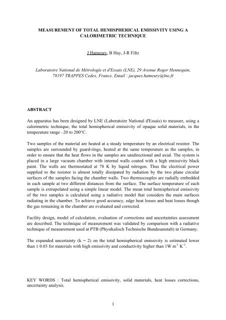
MEASUREMENT OF TOTAL HEMISPHERICAL EMISSIVITY USING ACALORIMETRIC TECHNIQUEJ Hameury, B Hay, J-R FiltzLaboratoire National de Métrologie et d'Essais (LNE), 29 Avenue Roger Hennequin,78197 TRAPPES Cedex, France, Email : jacques.hameury@lne.frABSTRACTAn apparatus has been designed by LNE (Laboratoire National d'Essais) to measure, using acalorimetric technique, the <strong>total</strong> <strong>hemispherical</strong> <strong>emissivity</strong> <strong>of</strong> opaque solid materials, in thetemperature range –20 to 200°C.Two samples <strong>of</strong> the material are heated at a steady temperature by an electrical resistor. Thesamples are surrounded by guard-rings, heated at the same temperature as the samples, inorder to ensure that the heat flows in the samples are unidirectional and axial. The system isplaced in a large vacuum chamber with internal walls coated with a high <strong>emissivity</strong> blackpaint. The walls are thermostated at 78 K by liquid nitrogen. Thus the electrical powersupplied to the resistor is almost <strong>total</strong>ly dissipated by radiation by the two plane circularsurfaces <strong>of</strong> the samples facing the chamber walls. Two thermocouples are radially embeddedin each sample at two different distances from the surface. The surface temperature <strong>of</strong> eachsample is extrapolated using a simple linear model. The mean <strong>total</strong> <strong>hemispherical</strong> <strong>emissivity</strong><strong>of</strong> the two samples is calculated using a radiative model that considers the main surfacesradiating in the chamber. To achieve good accuracy, edge heat losses and heat losses thoughthe gas remaining in the chamber are evaluated and corrected.Facility design, model <strong>of</strong> calculation, evaluation <strong>of</strong> corrections and uncertainties assessmentare described. The technique <strong>of</strong> measurement was validated by comparison with a radiativetechnique <strong>of</strong> measurement used at PTB (Physikalisch Technische Bundesanstalt) in Germany.The expanded uncertainty (k = 2) on the <strong>total</strong> <strong>hemispherical</strong> <strong>emissivity</strong> is estimated lowerthan ± 0.03 for materials with high <strong>emissivity</strong> and conductivity higher than 1W m -1 K -1 .KEY WORDS : Total <strong>hemispherical</strong> <strong>emissivity</strong>, solid materials, heat losses corrections,uncertainty analysis.1
2.1. Heating systemFigure 2 shows a cross-section <strong>of</strong> the heating system with the two samples and the thermalguard.For convenience, the following vocabulary is used:- meter plate : the system used to heat the samples, made <strong>of</strong> an electrical heater (disc) and <strong>of</strong>two copper discs to have a uniform temperature,- guard ring : the system used to heat the "samples rings", made <strong>of</strong> an electrical heater (ring)and <strong>of</strong> two copper rings,- samples rings : the two rings, heated by the guard ring, that surround the samples.This vocabulary is the same (or very closed) to the one used by people doing thermalconductivity measurements with guarded hot plates [4], [5].Two heaters are used, one for the two samples and the other one for the two samples rings.The electrical heaters are thin flexible heating elements consisting <strong>of</strong> a foil resistive elementlaminated between layers <strong>of</strong> polyimide film ; the limit temperature <strong>of</strong> the heaters is 210°C.The sample heater (disc shape) is sandwiched between 2 copper discs (diameter = 62.2 mm,thickness = 5mm) and the guard ring heater (ring shape) is sandwiched between 2 copperrings (inner diameter = 64.2 mm, outer diameter = 120.7 mm). The gap between the meterplate and the guard ring (Figure 3) is 1 mm wide except the opening, which is 0.1 mm wide.On each side <strong>of</strong> the heating system, the copper disc is attached to the ring by four bindingsmade <strong>of</strong> st<strong>ru</strong>ctural epoxy (section 5 mm × 5 mm). The guard ring temperature is controlled byan eight stages thermopile across the gap. Four stages <strong>of</strong> the thermopile are embedded in thecopper disc and the copper ring <strong>of</strong> each side <strong>of</strong> the heating plate. The thermopile wires areembedded in grooves filled with epoxy resin with a "high" thermal conductivity(1.8 W m -1 K -1 ). The temperature <strong>of</strong> the meter plate is controlled by a chromel/alumelthermocouple embedded in a copper disc.Axis61781095432Fig. 2. Cross section <strong>of</strong> the heating system with samples and rings : (1) samples; (2) samplesheating resistor; (3) copper discs; (4) guard ring heating resistor; (5) copper rings; (6) samplesrings; (7) thermopile, (8) thermocouples; (9) wires guard block; (10) wires.3
Revolutionaxis0,1 mm1,5 mmSampleSampleSample ringring10 mmCopper disk <strong>of</strong> the meter plateCopper ring <strong>of</strong> theguard ring5 mm1 mmFig. 3. Expanded view <strong>of</strong> the gap.2.2. SamplesTwo identical samples are needed for a measurement. The shape and dimensions <strong>of</strong> thesamples are shown by Figure 4 . Two radial holes (diameter 1.2 mm) are drilled in eachsample at known distances from the surface. If the material, to be characterized in <strong>emissivity</strong>,is thin then two samples <strong>of</strong> the material are stuck on two metallic discs with one or two holesfor thermocouples. If the material is a coating (paint, varnish, …) then the coating is appliedto two metallic discs.8.0 mm2.0 mmA - A∅ 62.2 mmA1 hole ∅ 1.2 mmdepth 15 mmSurface to becaracterized in<strong>emissivity</strong>90°1 hole ∅ 1.2 mmdepth 15 mm10 mmAFig. 4. Samples.4
2.3. Samples ringsEach sample is surrounded by a ring (called "sample ring") heated by the guard ring. Ideally,the samples rings would be made <strong>of</strong> the same material as the samples, in order to have thesame distribution <strong>of</strong> temperature as the sample (same gradient). In fact for convenience, threesets <strong>of</strong> samples rings can be used, one made <strong>of</strong> stainless steel, one made <strong>of</strong> aluminium alloyand one made <strong>of</strong> copper. The samples rings are fasten to the guard ring with screws. Threesmall clamps attached to each sample ring are used to press each sample on the meter plate.2.4. WIRES GUARD BLOCKA thermal guard (called "wires guard block") is used to heat all the wires that connect theheating system to the measuring devices or the electrical supplies (thermocouples, thermopile,electrical supplies). A similar system is described in [1] for an emissometer and in [5] for aguarded hot plate used for thermal conductivity measurement. The "wires guard block" isused to avoid an important local perturbation <strong>of</strong> the temperature distribution in the guard ring.The temperature <strong>of</strong> the block is controlled by a differential thermocouple between the blockand the guard ring.2.5. VACUUM CHAMBERThe chamber, made <strong>of</strong> stainless steel, has an internal surface <strong>of</strong> 1.36 m². The surface is coatedwith the Nextel Velvet Coating 811-21 black paint. The <strong>total</strong> <strong>hemispherical</strong> <strong>emissivity</strong> <strong>of</strong> thepaint, measured by PTB (Physikalisch Technische Bundesanstalt), is 0.943 at –60°C [6]. Awell (diameter 200 mm) is used to insert the heating system inside the chamber. The wall <strong>of</strong>the well is electro-polished to reduce the <strong>emissivity</strong>. A stacking <strong>of</strong> three screens, made <strong>of</strong>polished aluminium, is used to reduce the direct radiation flux, coming from the upper andhotter part <strong>of</strong> the well, inside the chamber. The gases are pumped out through an openingbetween the screens and the tube.2.6. VACUUM PUMPING SYSTEMThe pumping system is made <strong>of</strong> a turbomolecular pump associated with a rotary vane pumps.The gas in the chamber is pumped out, while the chamber is at ambient temperature, until thepressure reaches 5 10 -3 Pa. Then the liquid nitrogen is transferred into the dewar and thepressure in the chamber falls to less than 10 -3 Pa.5
2.7. INSTRUMENTATION AND CONTROL DEVICESThe temperatures in the heating plate (meter plate and guard ring), in the two samples and inthe samples rings are measured with chromel/alumel thermocouples connected to a highprecision calibrated voltmeter.The temperatures <strong>of</strong> the meter plate and the one <strong>of</strong> the guard ring are controlled by a dual loopEurotherm controller with a high resolution. Each loop <strong>of</strong> the controller pilots a DC powersupply.The intensity supplied to the meter plate is measured indirectly by measuring the voltage atthe terminals <strong>of</strong> a calibrated shunt resistor and the voltage is measured directly at theterminals <strong>of</strong> the heater (inside the meter plate).The pressure in the chamber is controlled with a Penning manometer.3. EMISSIVITY CALCULATION3.1. EMISSIVITY CALCULATIONThe <strong>total</strong> <strong>hemispherical</strong> <strong>emissivity</strong> is computed from the net heat-transfer rate <strong>of</strong> the circularsurfaces <strong>of</strong> the samples. Many models, more or less complex, can be built up to relate the<strong>emissivity</strong> to the electrical power supplied to the meter plate, to the surface temperature <strong>of</strong> thesamples and to the temperatures <strong>of</strong> the surfaces present in the surroundings <strong>of</strong> the samples.The complexity <strong>of</strong> the model depends on the number <strong>of</strong> surfaces that are considered. Most <strong>of</strong>the models found in literature are very simple, for example the <strong>emissivity</strong> <strong>of</strong> the chamberwalls is considered to be equal to one, like in [7] and [2], or the number <strong>of</strong> elements isreduced to the samples and the chamber walls [1].Our model is quite simple and considers 3 surfaces : the circular radiating surfaces <strong>of</strong> the twosamples, the surfaces <strong>of</strong> the rings (plane annular surfaces and cylindrical surfaces), thechamber walls. The model is built up using the "radiosity method", that is to say consideringthat the emission <strong>of</strong> the surfaces is Lambertian, the reflection on the surfaces is perfectlydiffuse and the spectral emissivities <strong>of</strong> the surfaces are independent <strong>of</strong> wavelengths.The heat balance equation for the two samples gives the relation :( P ) ⎛⎞elec.− PleaksSr⎜ ε ( )⎟c+ εr1−εcSs⎝ Scε⎠s=(1)4 ⎛ S ⎞⎛( )( − ) ⎞r⎜ + −⎟ −4Sr4 Pelec.Pleaksσ T− −⎜+⎟sεcεr1 εcεcσ Tc(1 εc) εrσ Tr⎝ Sc⎠⎝ ScSc⎠where : ε sis the <strong>total</strong> <strong>hemispherical</strong> <strong>emissivity</strong> <strong>of</strong> the samples, Pelec.is the electrical powersupplied to the meter plate, P leaksis the thermal power "lost" by the samples and the meterplate by other ways than radiation by the two circular surfaces <strong>of</strong> the samples, Ssis the sum<strong>of</strong> the two circular surfaces <strong>of</strong> the samples, ε cis the <strong>total</strong> <strong>hemispherical</strong> <strong>emissivity</strong> <strong>of</strong> the6
chamber walls, εris the mean <strong>total</strong> <strong>hemispherical</strong> <strong>emissivity</strong> <strong>of</strong> the rings surfaces, Sris thesurface <strong>of</strong> the samples rings radiating toward the chamber walls, S cis the surface <strong>of</strong> thechamber walls, σ is the Stefan-Boltzman constant, Tsis the mean surface temperature <strong>of</strong> thetwo samples, T cis the mean temperature <strong>of</strong> the chamber walls, T ris the mean surfacetemperature <strong>of</strong> the two rings.Pleaksis considered positive when the heat is lost by the samples or by the meter plate andnegative when the heat is received.The real surface temperatures <strong>of</strong> the two samples are slightly different, thus the mean surfacetemperature used to calculate the <strong>emissivity</strong> is calculated using the relation :1444⎛ S⎞s1Ts1+ Ss2Ts2T s=⎜⎟(2)⎝ Ss1+ Ss2⎠where : Tsis the mean surface temperature <strong>of</strong> the two samples, Ss1is the size <strong>of</strong> the circularsurface <strong>of</strong> sample no. 1, S s2is the size <strong>of</strong> the circular surface <strong>of</strong> sample no. 2, T s1is thesurface temperature measured for the sample no. 1, T s2is the surface temperature measuredfor the sample no. 2.3.2. UNCERTAINTY OF THE MODELThe uncertainty <strong>of</strong> the model has been evaluated by comparison to a model considering fivesurfaces. The "t<strong>ru</strong>e" value <strong>of</strong> the power radiated by the samples is supposed to be the onegiven by the five surfaces model (chamber walls, samples, rings, screens around the rings,screens and opening <strong>of</strong> the well). The relative difference between the <strong>emissivity</strong> calculatedwith the 3 surfaces model and the "t<strong>ru</strong>e" <strong>emissivity</strong> is lower than 0.11%.3.3. HEAT LOSSES EVALUATIONThe parasitic heat fluxes lost or gained by the samples and the meter plate are :- the radiation flux lost by the edge <strong>of</strong> the samples (cylindrical surface),- the radiation flux lost by the edge <strong>of</strong> the meter plate (copper discs),- the conduction flux between each sample and the corresponding sample ring,- the flux lost by conduction or convection though the gas remaining in the chamber.3.2.1. EDGE LOSSES BY RADIATIONThe geometry <strong>of</strong> the gap is shown by Figure 3. A radiosity model was built up to calculate theradiative net heat flux lost by the sample edge (cylindrical surface). Due to the symmetry <strong>of</strong>the system, the calculation was done only for one side <strong>of</strong> the heating system. In the modeleach surface is supposed to be isothermal. So the calculation was done considering the meantemperature at half thickness <strong>of</strong> the sample and <strong>of</strong> the sample ring. The mean temperatures arecalculated from the measured temperatures.7
The results show that, if the mean temperature <strong>of</strong> the sample is the same as the one <strong>of</strong> thesample ring, the gap radiates toward the chamber like a black body at the mean temperature <strong>of</strong>the sample. This is not surprising because <strong>of</strong> the low value <strong>of</strong> the ratio surface <strong>of</strong> the opening<strong>of</strong> the gap to internal surface. Thus, if the mean temperature <strong>of</strong> the sample is the same as theone <strong>of</strong> the sample ring, the heat flux lost by radiation by the edge <strong>of</strong> the sample depends onlyon the ratio <strong>emissivity</strong> <strong>of</strong> the sample edge to <strong>emissivity</strong> <strong>of</strong> the edge <strong>of</strong> the sample ring;Figure 5 shows that evolution. If the mean temperatures <strong>of</strong> the sample and <strong>of</strong> the ring are thesame and if the emissivities <strong>of</strong> the sample edge is the same as the one <strong>of</strong> the edge <strong>of</strong> the ring,then the heat flux lost by radiation by the sample edge is equivalent to an <strong>emissivity</strong> <strong>of</strong> 0.0032for the circular surface <strong>of</strong> the sample.0.8Ratio : ( heat flux lost by radiation /measured heat flux) * 1000.70.60.50.40.30.20.10Emissivity <strong>of</strong> the circular surface <strong>of</strong> the sample =0.90 1 2 3 4 5 6 7 8 9 10 11 12Ratio : Emissivity <strong>of</strong> the cylindrical surface <strong>of</strong> the sample / <strong>emissivity</strong> <strong>of</strong> the cylindrical surface<strong>of</strong> the ringFig. 5. Radiative heat flux lost by the edge <strong>of</strong> the sample3.2.2. EDGE LOSSES BY CONDUCTIONA difference <strong>of</strong> temperature between each sample and the corresponding sample ring canoccur if the thermal contact resistance between the sample ring and the guard ring is differentthan the one between the sample and the meter plate. The temperature <strong>of</strong> each ring ismeasured using two thermocouples (like for samples). The value evaluated for the heattransfer coefficient by conduction through the four thermocouples embedded in the samples is0.11 W/K.The heat flux by conduction between the meter plate and the guard ring is supposed to benegligible because the temperature <strong>of</strong> the guard ring is controlled to be almost the same as theone <strong>of</strong> the meter plate. Nevertheless, a term <strong>of</strong> uncertainty is considered for that heat flux.8
3.2.3. HEAT LOSS BY THE GAS REMAINING IN THE CHAMBERDuring <strong>emissivity</strong> measurements the gas remaining in the chamber is at a pressurebelow 10 -3 Pa. The longer distance between the sample and a point <strong>of</strong> the chamber walls isabout 300 mm. At a pressure below 10 -2 Pa, the mean free path for a molecule <strong>of</strong> air is longerthan 0.64 m [8], that is to say the mean free path is longer than the greatest dimension <strong>of</strong> thechamber. Thus the equivalent thermal conductivity <strong>of</strong> air is proportional to pressure (kineticgas theory [8]).The flux lost by the circular surface <strong>of</strong> a sample is given by the relation [8]:Φair= K Ssamplesa P ( Tsample−Twalls)(3)where : K is a characteristic <strong>of</strong> the gas (K= 1.2 for nitrogen), S samplesis the surface <strong>of</strong> thesample, a is the accommodation coefficient ( a = 1 for air at 77 K), P is the pressure <strong>of</strong> thegas, Tsampleis the surface temperature <strong>of</strong> the sample and T wallsis the temperature <strong>of</strong> thechamber walls.<strong>Measurement</strong> <strong>of</strong> variations <strong>of</strong> the power supplied to the meter plate versus pressure in thechamber were made, the results are given in Table I. The measurements were made with low<strong>emissivity</strong> samples ( ε = 0. 055 ) at 100°C. The power varies linearly with the pressure for apressure below 2 10 -2 Pa (molecular regime). The heat transfer coefficient was calculatedconsidering that the power measured at 2 10 -4 Pa is the same as the one without any molecule<strong>of</strong> gas. The theoretical heat transfer coefficient given by Eq. (3) is also given in Table I. Themeasured heat transfer coefficient is <strong>of</strong> the same order than the one given by the theory for apressure below 2 10 -2 Pa (molecular regime).Table II give the <strong>emissivity</strong> equivalent to the power transferred by the remaining gas fordifferent temperatures. A fairly good vacuum is needed to have a negligible error due to heattransfer by air, a pressure lower than 10 -3 Pa induces a negligible error for all the temperaturerange.9
PressurePowerHeat transfer coefficientthrough the gasHeat transfer coefficientcalculated using Eq. (3)(Pa)(W)(W/(m² °C))(W/(m² °C))2.00 × 10 -4 0.366 - 2.40 × 10 -45.00 × 10 -4 0.367 5.60 × 10 -4 6.00 × 10 -42.00 × 10 -3 0.37 2.20 × 10 -3 2.40 × 10 -35.00 × 10 -3 0.375 5.00 × 10 -3 6.00 × 10 -32.00 × 10 -2 0.406 2.20 × 10 -2 2.40 × 10 -25.00 × 10 -2 0.435 3.80 × 10 -2 6.00 × 10 -22.00 × 10 -1 0.491 6.90 × 10 -2 2.40 × 10 -1Table I.Power supplied to the meter plate versus pressure,Heat transfer coefficient through the gas.PressureEmissivity equivalent to the heat loss through the gasSurface temperature(Pa) -20 °C 20 °C 100 °C 200 °C1.0 × 10 -4 0.0001 0.0001 0.0000 0.00005.0 × 10 -4 0.0005 0.0003 0.0002 0.00011.0 × 10 -3 0.0009 0.0006 0.0003 0.00025.0 × 10 -3 0.0046 0.0031 0.0016 0.00081.0 × 10 -2 0.0092 0.0062 0.0032 0.00172.0 × 10 -2 0.0183 0.0125 0.0065 0.0034Table II.Emissivity equivalent to the heat loss through the gas.4. MEASUREMENT PROCEDUREFirst, the two samples are characterized geometrically (diameter <strong>of</strong> the radiating surface,thickness, positions <strong>of</strong> the two radial holes).The samples are fasten on the heating system with thermal grease applied between thesamples and the meter plate to provide a good thermal contact, thermal grease is also applied10
etween the sample rings and the guard ring. The thermal grease is used to reducetemperature unbalance between the two sides and between the samples and the rings and toimprove the homogeneity <strong>of</strong> temperature.The heating system (with the samples and the rings) is suspended at middle height <strong>of</strong> thevacuum chamber. The air is pumped out until the pressure is below 5 × 10 -3 Pa. The dewar isfilled with liquid nitrogen until the level exceeds <strong>of</strong> 5 cm the flange <strong>of</strong> the vacuum chamber.The temperatures <strong>of</strong> the heating system (meter plate and guard ring) are stabilised at therequired level, the time to get a good stability is about four hours.The temperatures <strong>of</strong> the two samples and <strong>of</strong> the two sample rings are measured to control thatthe two samples and the two rings are approximately at the same temperature.The temperatures in the two samples and in the two rings are measured as well as theelectrical power supplied to the meter plate. Those measurements are repeated at least 30times and the mean <strong>emissivity</strong> is calculated using the model.5. ASSESMENT OF UNCERTAINTIESTable III gives the list <strong>of</strong> causes <strong>of</strong> uncertainty that are considered.The numerical values were evaluated for the particular case <strong>of</strong> a black paint(thickness = 50 µm) applied on copper substrates, the samples were at 20 °C and themeasured <strong>total</strong> <strong>hemispherical</strong> <strong>emissivity</strong> was 0.921.All the uncertainties given in the table are expanded uncertainties with a coverage factork = 2.11
Parameter or modelValue & ExpandedUncertainty (k = 2)Induced expandeduncertainty on themeasured <strong>emissivity</strong>Surface <strong>of</strong> the samples 0.00608 ± 4 10 -6 m 2 6.1 x 10 -4Surface <strong>of</strong> the chamber 1.36 ± 0.1 m 2 3.3 x 10 -4Surface <strong>of</strong> the samples rings 0.0240 ± 0.0008 m 2 4 x 10 -5Mean <strong>total</strong> <strong>hemispherical</strong> <strong>emissivity</strong> <strong>of</strong> the 0.92 ± 0.05 1.8 x 10 -3chamber wallsMean <strong>total</strong> <strong>hemispherical</strong> <strong>emissivity</strong> <strong>of</strong> the 0.8 ± 0.1 1.3 x 10 -4ringsElectrical power 2.31950 ± 7 10 -5 W 2.8 x 10 -5Mean surface temperature <strong>of</strong> the samples 293.5 ± 0.2 K 2.5 x 10 -3Mean temperature <strong>of</strong> the chamber walls 78 ± 2 K 5 x 10 -4Mean surface temperature <strong>of</strong> the rings 293.0 ± 0.2 K 4 x 10 -6Edge heat loss by radiation 0.0076 ± 0.002 W 8 x 10 -4Edge heat loss by conduction between the 0.006 ± 0.01 W 4 x 10 -3samples and the ringsEdge heat loss by conduction between the 0 ± 0.006 W 2.4 x 10 -3meter plate and the guard ringHeat loss by air 0.00073 ± 0.0005 W 2 x 10 -4Model used for <strong>emissivity</strong> calculation ± 0.001 1 x 10 -3Random variations <strong>of</strong> measured emissivities ± 0.002 2 x 10 -3Measured Emissivity 0.921 0.0062Table III.Budget <strong>of</strong> uncertainty for a black paint at 20 °C.6. VALIDATION OF MEASUREMENTSThe measurement technique was validated by comparison with a radiative technique <strong>of</strong>measurement used at PTB (Physikalisch Technische Bundesanstalt) in Germany. Themeasurement technique <strong>of</strong> PTB is described in [9]. PTB measured the <strong>total</strong> directional<strong>emissivity</strong>, for many directions between 0° and 75° (angle to the normal), by comparison to a12
lack-body. A <strong>total</strong> radiometer was used for the comparison. A model <strong>of</strong> angular variationwas then applied and the <strong>hemispherical</strong> <strong>total</strong> <strong>emissivity</strong> was calculated by integration over thehalf-space.The material selected for the comparison was AISI 304 L stainless-steel. The samples weresandblasted and oxidised by heating in air at 360 °C. The results are givenin Table IV. For LNE, the results are the mean emissivities <strong>of</strong> the two samples. For PTB, the<strong>emissivity</strong> given for 40°C is the one measured on sample no.1. For 150°C and 200°C, thevalues are the means <strong>of</strong> the emissivities measured independently on the two samples. For150°C and 200°C, the differences between the emissivities <strong>of</strong> the two samples, measured byPTB, are lower than 0.006.The results <strong>of</strong> the two laborarories are in agreement within the combined uncertainties. Theuncertainties <strong>of</strong> LNE are much lower than those <strong>of</strong> PTB, probably because the method <strong>of</strong>measurement is more direct and requires fewer parameters to be measured (directional<strong>emissivity</strong> for PTB). For the temperature 40 °C, the uncertainty <strong>of</strong> PTB is large because theradiative emission <strong>of</strong> the sample is low.TempératureTotal <strong>hemispherical</strong> Emissivity (oxidised AISI 304L stainless steel)LNE PTB PTB - LNE40 °C 0.399 ± 0.0060 0.420 ± 0.04 0.021150 °C 0.427 ± 0.0068 0.433 ± 0.02 0.006200 °C 0.441 ± 0.0075 0.438 ± 0.02 -0.003Table IV.Comparison <strong>of</strong> the results <strong>of</strong> PTB and LNE7. CONCLUSIONLNE has developed an apparatus for measuring <strong>total</strong> <strong>hemispherical</strong> <strong>emissivity</strong> <strong>of</strong> solid opaquematerials. The <strong>emissivity</strong> can be measured in the temperature range –20 to 200 °C, onmaterials with a thermal conductivity higher than 0.2 W m -1 K -1 . The sources <strong>of</strong> errors and thesources <strong>of</strong> uncertainties have been analysed in detail. The sources <strong>of</strong> errors that have to beconsidered are the parasitic heat fluxes at the edge <strong>of</strong> the samples.The main sources <strong>of</strong> uncertainties are :- the uncertainty on the heat flux between the samples and the rings, due to the uncertaintyon the difference <strong>of</strong> temperature between the samples and the rings,- the uncertainty on the surface temperatures <strong>of</strong> the samples which depends on theconductivity <strong>of</strong> the material and <strong>of</strong> the level <strong>of</strong> temperature,- the uncertainty on the heat flux between the meter plate and the guard ring.For materials with a thermal conductivity higher than 0.5 W m -1 K -1 , the uncertainty on the<strong>total</strong> <strong>hemispherical</strong> <strong>emissivity</strong> remains lower than ± 0.03. This level <strong>of</strong> uncertainty is verysatisfactory for the majority <strong>of</strong> the applications which need the knowledge <strong>of</strong> <strong>total</strong><strong>hemispherical</strong> <strong>emissivity</strong>.13
REFERENCES1. M.C. Certiat, O. Mace, Caractérisation expérimentale de l'émissivité : Besoins pourAérospatiale, Méthodes développées, Société Française des Thermiciens, SectionRayonnement, Journée d'étude du 17 Avril 1991 sur Pyrométrie Optique, Mesures desémissivités.2. K. Fukuzawa, A. Ohnishi, Y. Nagasaka, Total Hemispherical Emittance <strong>of</strong> PolyimideFilms for Space Use in the Temperature Range from 173 to 700 K, Int. Jour. <strong>of</strong>Thermophysics, Vol. 23, No. 1, January 2002, pages 319-331.3. D. Naws, B. Pouilloux, Total Hemispherical high temperature Emissivity measurementusing the static calorimetric method test specimen feasibility study, High Temp. Chem.Proccesses, 3, Feb<strong>ru</strong>ary 1994, pages 99-108.4. Thermal insulation -- Determination <strong>of</strong> steady-state thermal resistance and relatedproperties -- Guarded hot plate apparatus, ISO 8302, 1991, International Organization forStandardization, Geneva, Switzerland5. R. R. Zarr, W. Healy, J. J. Filliben, D R. Flynn, Design concepts for a new guarded hotplate apparatus for use over an extended temperature range, R. R. Zarr, W. Healy, J. J.Filliben, D R. Flynn, Reprinted from STP 1426, ASTM International Standards,Insulation Materials, Testing and Applications, V4, 2002 – ISBN 0-8031-2898-3.6. J. Lorengel and R. Todtenhaup, in Wärmeleitfähigkeit, Gesamtemissionsgrade undspektrale Emissionsgrade der Beschichtung Nextel-Velvet Coating 811-21, PTB-Mitteilungen 106 4/96.7. Y.S. Touloukian , D.P. DeWitt , Thermal Radiative Properties , Metallic Elements andAlloys. Thermophysical Properties <strong>of</strong> Matter, Volume 7, pages 40a-42a, IFI/Plenum. NewYork–Washington. 1970.8. G. ROMMEL, Gaz à très basse pression – Généralités , Ref B4020, Techniques del’Ingénieur, Paris, 1984.9. J. Lohrengel, Determination <strong>of</strong> the surface temperature <strong>of</strong> poor heat conductingmaterials by radiation measurements for -60 °C to +250 °C in vacuum, Wärme- undSt<strong>of</strong>fübertragung, 21 (1987), p. 1-5.14