AFVA Aircraft Operations Manual - Air France Virtual Airlines
AFVA Aircraft Operations Manual - Air France Virtual Airlines
AFVA Aircraft Operations Manual - Air France Virtual Airlines
Create successful ePaper yourself
Turn your PDF publications into a flip-book with our unique Google optimized e-Paper software.
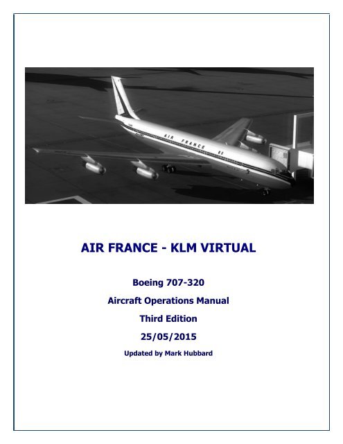
AIR FRANCE - KLM VIRTUALBoeing 707-320<strong><strong>Air</strong>craft</strong> <strong>Operations</strong> <strong>Manual</strong>Third Edition25/05/2015Updated by Mark Hubbard
Boeing 707-320 Operating <strong>Manual</strong>Table of ContentsWelcome ........................................................................................................................................................ 3History and Overview ...................................................................................................................................... 4History of the B707: .................................................................................................................................... 4Specifications .................................................................................................................................................. 6Tutorial – How to fly the B707 ......................................................................................................................... 8Description of the Captain's panel: ............................................................................................................. 11M-group instruments (For Captain's and FO's use) ...................................................................................... 15Description of the First Officer's panel: ....................................................................................................... 16Description of the overhead panel: ............................................................................................................. 17Description of the Flight Engineer's Panel ................................................................................................... 19Description of the pedestal ........................................................................................................................ 22Description of the autopilot panel ............................................................................................................... 23Description of the communication panel ..................................................................................................... 24Tutorial flight ................................................................................................................................................ 25Flight Planning .......................................................................................................................................... 25Take-Off and Initial Climb .......................................................................................................................... 29Enroute with climb and cruise .................................................................................................................... 29The descent: ............................................................................................................................................. 31The landing............................................................................................................................................... 32Acknowledgements and Legal Matters ............................................................................................................ 332
Boeing 707-320 Operating <strong>Manual</strong>WelcomeWelcome to the <strong>Air</strong> <strong>France</strong> - KLM <strong>Virtual</strong> <strong><strong>Air</strong>craft</strong> Operating <strong>Manual</strong> (AOM) for the B707.This AOM is based upon the DVA Fleet Installer aeroplane. We are always seeking to improve theaccuracy of this AOM.Should you have questions about the specifics of this aeroplane or this manual or aviation in general, youshould create a helpdesk issue at our website, http://www.afva.net that states your question and we willdo our best to answer your questions.If you would like to receive virtual flight training that is modelled after real world training, go to the PilotCentre on our website, http://www.afva.net where you can sign up for flight instruction in the <strong>AFVA</strong><strong>Virtual</strong> Flight Academy.The B707 AOM is not designed for beginners of Flight Simulation. This AOM sets out to explain thehandling of our B707 not how simulation flying works we assume the pilot knows how to fly an airlinerwith all the necessary procedures.3
Boeing 707-320 Operating <strong>Manual</strong>History and OverviewHistory of the B707:America entered the age of the jet transport on July 15, 1954, when the Boeing 707 prototype, the model367-80, made its maiden flight from Renton Field, south of Seattle.Production go-ahead for the Dash 80 was announced by Boeing Aug. 30, 1952, as a company-financed$16 million investment. The aeroplane rolled from the factory less than two years later, on 14 th May1954. Its first flight that July marked the 38 th anniversary of The Boeing Company.Powered then by four Pratt & Whitney JT3 turbojets, mounted under wings swept back 35 degrees, theDash 80 established the classic configuration for jetliners to come. It also set new speed records eachtime it flew. This was illustrated March 11, 1957, when it streaked nonstop on a press demonstrationflight from Seattle to Baltimore in 3 hours 48 minutes at an average speed of 612 mph.Commercial history was made Oct. 26, 1958, when Pan American World <strong>Air</strong>ways inaugurated trans-Atlantic 707 jet service between New York and Paris; jetliners then rapidly entered service throughout theworld.The first commercial 707s, labelled the 707-120 series, had a larger cabin and other improvementscompared to the prototype. Powered by early Pratt & Whitney turbojet engines, these initial 707s hadrange capability that was barely sufficient for the Atlantic Ocean. Following the less-than-stellar results,Boeing released the 120B series which was an improved version of the -120 with P&W JT3D-1 turbofans.A number of variants were developed for special use, including shorter-bodied aeroplanes and the 720series, which was lighter and faster with better runway performance.Boeing quickly developed the larger 707-320 Intercontinental series with a longer fuselage, bigger wingand higher-powered 4 P&W JT4A-3 turbofans for intercontinental and transoceanic flights. With theseimprovements, which allowed increased fuel capacity from 15,000 gallons to more than 23,000 gallons,the 707 had truly intercontinental range of over 4,000 miles in a 141-seat (mixed class) seatingconfiguration. The first delivery was on July, 19 1959. It was this variant that created the "legend" of theB707.Early in the 1960s, the Pratt & Whitney JT3D turbofan engines were fitted to provide lower fuelconsumption reduce noise, and further increase range to about 6,000 miles.A second leg in the development was the B707-020 for short- and medium-range operations. This"smaller sister" of the B707 was significant different from the original B707 and by this the result was acomplete new aircraft called B720. It was equipped with 4 Pratt-&-Whitney-JT3D-1-Turbofans with athrust of 17000 lbf (75.6 kN). The first flight was on 23 rd November 1959.4
Boeing 707-320 Operating <strong>Manual</strong>The B707 was produced until 1979 and operated by many airlines in the world for domestic as well as forintercontinental flights.Nowadays you will find very few in commercial use but it is still used for military purposes as the KC-135(air tanker) or as E3A in AWACS missions as well as for military transports in several variants.In total Boeing delivered 1011 aircraft including the B720 and the military versions.During the 1960s and early 70s the B707 was almost synonymous for jet-airliners and along with theVickers VC10, gave birth to the term the jet-set, referring to those wealthy individuals who could affordto fly as passengers.Additional information:As one of the first and one of the most popular jetliner of its era, the B707 raised the prestige of everyairline that operated one. It is also the pride of our <strong>AFVA</strong>'s historical program.The B707 could be seen in every part of the world, from New York to Tokyo or Sydney as well as inAbidjan and Barbados or Nadi.One of the most amazing flights with the B707 was in the 70s when a daily Pan American Flight from LosAngeles (KLAX) to New York (KJFK) ... westbound! The Routing was Los Angeles - Honolulu - Tokyo -Hong-Kong - Bangkok - Delhi - Karachi - Tehran - Beirut - Istanbul - Frankfurt - London - New York.Flights with the B707 were a real challenge to the pilots and the flight-engineer because it was notequipped with the modern navigation tools that pilots today enjoy such as FMC, RNAV or GPS. Thecomplete flight had to be planned exactly including route, timing and fuel. In the simulation world, thechallenge is the same.The means of navigation were paper charts, paper maps, compasses, radio-navigation, INS and aDoppler-radar system.5
Boeing 707-320 Operating <strong>Manual</strong>SpecificationsTYPE 720 (707-020) 707-120B 707-320BDIMENSIONSLength 136 ft 2 in (41.25 m) 145 ft 1 in (44.07 m) 152 ft 11 in (46.61 m)Tail Height 41 ft 7 in (12.65 m) 42 ft 5 in (12.93 m)Wingspan 130 ft 10 in (39.90 m) 145 ft 9 in (44.42 m)Wing AreaFuselage Width 12 ft 4 in (3.76 m)Wheel BasePOWERPLANTSEngine Type Pratt & Whitney JT3C-7 Pratt & Whitney JT3D-1 P&W JT3D-3 P&W JT3D-7Maximum Rated Thrust(SLS, ISA)WEIGHTSEmpty Weight12,000 lbf (53.3 kN) 17,000 lbf (75.6 kN)103,145 lb(46,785 kg)18,000 lbf(80 kN)19,000 lbf(84.4 kN)122,533 lb(55,580 kg) 146,400 lb (66,406 kg)Maximum Gross WeightMaximum TakeoffWeightMaximum LandingWeightMaximum Zero-FuelWeightCAPACITIESMaximum Fuel222,000 lb(100,800 kg)16,060 US gal(60,900 l)Max Seating 140257,000 lb(116,570 kg)17,330 US gal(65,590 l)110 (2 class)179 (1 class)Cockpit Crew 3Maximum PayloadMaximum Cargo Volume333,600 lb(151,320 kg)23,820 US gal(90,160 l)147 (2 class)202 (1 class)6
Boeing 707-320 Operating <strong>Manual</strong>OPERATIONAL LIMITSService CeilingNormal Cruise Speed 540 KIAS(1000 km/h) 525 KIAS (972 km/h)Max Cruise SpeedOperating Range (MaxPayload3,680 nm (6,820 km) 3,735 nm (6,920 km)Maximum Range 3800 nm (7,040 km) 4,700 nm (8,704 km) 5,750 nm (10,650 km)Takeoff Distance (MaxTakeoff Weight)8,300 ft (2,515 m) 11,000 ft (3,330 m) 10,840 ft (3,280 m)Landing Distance (MaxLanding Weight – Flaps 5,750 ft (1,740 m) 6,200 ft (1,875 m) 5,950 ft (1,813 m)20)Stall Speed – Flaps UpStall Speed – Full Flapsand Max Landing WeightMaximum Indicated<strong>Air</strong>speedSource: "Boeing 707 aircraft characteristics" (The Boeing company commercial airplane division)7
Boeing 707-320 Operating <strong>Manual</strong>Tutorial – How to fly the B707As we review this AOM, we have to take into consideration the long service life of the Boeing 707. Shehas had approximately 50 years of flying and during that time aviation as a whole has undergone quite afew changes as aeronautical technologies have improved. For this reason, the AOM that you are readingmay create some differences between available models.For ease of reading, this AOM describes the functions of the B 707 as available in the <strong>AFVA</strong> fleet library.A deeper description of the avionics equipment will be omitted in this AOM. The knowledge of thosecomponents is explained in other <strong>AFVA</strong> documents which can be found in the Pilot Centre underDocuments Library.The Boeing 707 has a 3-crew-cockpit consisting of:- Captain- First Officer- Flight EngineerFor this reason the aircraft cockpit has three main panels:The captain's panel:8
Boeing 707-320 Operating <strong>Manual</strong>The first officer's panel:The flight engineer's panel:9
Boeing 707-320 Operating <strong>Manual</strong>Detailed Panel DescriptionsThe pedestal with the autopilot-panel:The overhead-panel:10
Boeing 707-320 Operating <strong>Manual</strong>Description of the Captain's panel:C-group instruments: (for the captain's use only):C01 <strong>Air</strong>speed indicator- IAS (white) Needle- Max-speed VMO (green/white) Needle- Speed-bugo The speed-bug is just an indication. It is not for adjusting the ATHRo Please note: The B 707 doesn't have an ATHR-function- Speed-bug selectorC02 Turn indicator (TI)The TI is a spin and gravity controlled instrument and indicates the coordination of turns or theappearance of slipsC03 MACH-indicatorThis gauge indicates the Mach number between MACH 0.3 and MACH 1.011
Boeing 707-320 Operating <strong>Manual</strong>C04 Master warning indicatorThis indicator illuminates if any warning is detected.C05 Horizontal Flight Director (HFD)The Horizontal Flight Director consists of the following components:- Gyro flag warning (a red flag labelled as "G")- Bank angle indicator (on the upper circumference) with the roll indicator- Pitch scale indicating the pitch in degrees (in the centre)- Flight director (FD) warning flag (labelled as "FD")- Pitch command bar, controlled by the selected device (FD, GS)- Attitude Indicator - this indicates the attitude of the plane relative to the horizon- Turn indicator (see C02)- Localizer indicator (located at the bottom of this instrument)- Localizer indicator warning flag (labelled as "LOC")- Horizon line, Symbolizes the horizon (The amber line in the centre of the instrument)- Roll command bar, controlled by the selected device (FD, GS)- Relative speed indicator this indicates the speed deviation from the speed bug in the airspeedindicator (see C01). This is located on the left side of the instrument- Relative speed indicator warning flag. (Labelled as "FS")- Glide slope indicator (GS) on the right side of the instrument- Glide slope warning flag. (labelled as "GS")C06 Magnetic heading deviation indicator (MHDI)This is the main instrument cluster used for lateral navigation since the B 707 doesn't have an FMC. The MHDIconsists of the following components:- The heading group (Amber coloured):- Heading bug at the circumference of the scale shows the preset heading- Heading selector knob controls the heading bug (Lower right corner)- The VOR group (White coloured)- Course counter (Left upper corner) shows the selected radial for VOR 1- Course cursor, shows the selected radial for VOR1 graphically- Navigation warning flag (labelled as NAV)- DME indicator (Right upper corner) shows the distance to VOR1 in nm- Glide slope deviation bar (right side of the instrument)- Glide slope indication warning flag (labelled as GS)- Course deviation bar, indicates course deviation- Course selector for adjusting the required VOR radial12
Boeing 707-320 Operating <strong>Manual</strong>- Course deviation scale (Horizontal scale in the centre)- TO/FROM indicator, the arrow extending the course deviation barC07 Ground proximity warning signal (GPWS)The GPWS emits an acoustic sound in case of ground proximityC08 Barometric altimeter- 100 ft pointer, the centred rotating hand- Altitude numerical counter, the lager window in the upper half of the instrument- Altimeter setting windows, left in millibars and right in inches/Hg- Barometric setting knob in the left lower cornerC09 Radio magnetic indicator (RMI)- The RMI provides the radio and magnetic bearing for the VOR and ADF indication- The dashed pointer indicates the bearing of the VOR1 or ADF, depending on its selection- The double lined pointer indicates the bearing of the VOR1 or ADF, depending on itsselection- With the left selector knob the pilot can select the indication between VOR1 or ADF- With the right selector knob the pilot can select the indication between VOR2 or ADFC10 DME indication for VOR2- The DME for VOR1 is indicated in the MHDI (C06)C11 Pneumatic brake leverC12 Vertical Speed Indicator (VSI)- Indicates the vertical speed in 1000 ft/min- Negative rate (below 0) indicates a descent- Positive rate (above 0) indicates a climbC13 Clock- The hands indicate the set local time in hours and minutes- Hours adjust knob (Left lower corner)- Minutes adjust knob (Right lower corner)13
Boeing 707-320 Operating <strong>Manual</strong>C14 Radio altimeter- The radio altimeter indicates the height above ground in feet- Decision height selector knob for adjusting the decision height- Radio altimeter warning flag covering the lower height indication if the altimeter is inoperableC15 Flight director panel- Flight director indication light indicates the FD as active- The flight director switch activates the flight director- The indication of the flight director is displayed in the HFD (See C05)C16 Icing indicationC17 True airspeed indicator (TAS)- This gauge indicates the true airspeedC18 Spare horizon flight directorThe spare HFD provides the same functions as the HFD (See C05). <strong>Air</strong>liners have to have at least twoHFDs at a minimum but three HFDs are better. One is placed in the Captain's panel, one in the FO's paneland the spare HFD is in the middle sectionC19 Oil pressure warning lamps- Left lamp for the pressure in engine 1- Right lamp for the pressure in engine 2- The indications for engines 3 and 4 are displayed in M08C20 Altitude alert counter- The altitude to be alerted (Target altitude and or cruise level, etc.) can be adjusted here- Before reaching a window of 1000 ft around the alert altitude, the crew will be alerted by a buzzer14
Boeing 707-320 Operating <strong>Manual</strong>M-group instruments (For Captain's and FO's use)M01 Horizontal Engine IndicatorsEngines 1 through 4 are listed horizontally from left to right. Each engine has five vertical indicators ascovered in MO2.M02 Engine indications verticalFor every engine there is a group of five indicators which are described here from top to bottom:- Engine pressure ratio indicator (EPR):o Indicates the ratio of exhaust gas pressure (Pt7) to inlet air pressure (Pt2). EPR=Pt7/Pt2and is a parameter of the thrust developed by the engine. This indicator is used as aprimary thrust setting instrument since EPR is directly proportional to thrust.- N1 tachometero Indicates low-pressure compressor in rpm.o It is powered by a tachometer generator which is driven by the N1 shaft.- Engine Exhaust Gas Temperature Indicators (EGT)o Indicates turbine exhaust gas temperature in hundreds of degrees centigrade- N2 tachometero Indicates high-pressure compressor in RPM- Engine fuel flow meters and indicators for total flowo The bug shows fuel flow to respective engine in pounds per hour X 1000.o The digital counter shows total pounds consumedM03 Engine fire handles and indicators- Each engine has its own handle and indicators (1 - 4)- The handle illuminates in case of detected significant temperature rise- Pulling a handle:o Arms the discharge buttono Closes the following valves: engine anti-ice, low pressure bleed, fuel shutoff valve and thehydraulic-pump supply valveooTrips the engine generatorThis action disconnects the respective engine from all systems and starts the fireextinguishing processImportant note: In case of engine fire after pulling the fire handle all systems for supplyingthe engine must be checked manually as well and the crew has to make sure that the engineis completely disconnected.15
Boeing 707-320 Operating <strong>Manual</strong>M04 Wheel well fire warning lightM05 Gear door warning lightM06 Flaps indicators panelM07 Flaps indicators lightsM08 Oil pressure warning light (see C19)Description of the First Officer's panel:The first officer's panel provides the same instruments as the captain's panel. See the description for thecaptain's panel.16
Boeing 707-320 Operating <strong>Manual</strong>Description of the overhead panel:O01 Emergency Flap Switches- The Norm-Bypass Switcho Norm: Disarms electric operation of trailing edge flaps and permits hydraulicoperation.o Bypass: Bypasses hydraulic trailing edge flap system and arms the adjacent INBD orOUTBD switches.- INBD and OUTBD switcheso Both switches override the normal operation of the flaps when operated in "up" or "down”positions.O02 Light ControlsThese switches control lighting for the flight deck.O03 Engine Start Controls (Engine 1 and 2)- Ground-starto This has to be selected for an engine start on the ground- Flight start is needed in situations like:o During takeoffo For immediate relight in the event of a flameout, or for windmill starting in flight,17
Boeing 707-320 Operating <strong>Manual</strong>O04 ADF 1 Control PanelO05 CIVA INS Main control panelThis instrument is explained more in depth in the separate manual that was extracted when the aircraftwas installed.O06 Ground Start Selector switchThis switch allows enough air pressure to be generated in the engines to allow for a ground start to beselected.O07 Engine Start Controls (Engines 3 and 4)- Ground-starto This has to be selected for an engine start on the ground- Flight start is needed in situations like:o During takeoffo For immediate relight in the event of a flameout, or for windmill starting in flight,O08 Compass Illumination SwitchO09 Oxygen pressure SwitchThis switch has to be set to guarded mode in all normal flight situationsO10 Emergency Exit LightsWhen this switch has been enabled, the emergency exit signs and illuminated strips are turned on.O11 Crew Call PushbuttonO12 ADF 2 Control PanelO13 Light Controls for the F/O panelO14 Window Heating ControlsO15 Pitot Heating ControlsO16 Nacelle Anti Ice ControlsO17 Wing Anti Ice PanelO18 Windshield Wiper SwitchO19 External Lighting Switches18
Boeing 707-320 Operating <strong>Manual</strong>Description of the Flight Engineer's PanelFE01 - FE08 Description of the electrical panelFE01 Bus tie breaker switchesThere is a Bus Tie Breaker (BTB) switch for every engine (1-4) in combination with the respective indicatorlight.FE02 Generator breaker switchesThere is a Generator Breaker (GB) switch for every engine (1-4) with its respective indicator light.FE03 Generator control relaysThere is a Generator Control (GC) relay for every engine (1-4) with its respective indicator light.FE04 Battery switch19
Boeing 707-320 Operating <strong>Manual</strong>FE05 External power switch with- Bus tie indication light- External power availability lightFE06 Essential power- The essential power selector switch for selecting from Gen 1 to Gen 4 and external power.- The essential power failure light illuminates if no essential power is available.FE07 KW meters for engines 1 - 4FE08 First officer's panel illumination switchFE09 - FE14 Description of the pneumatic panelFE09 <strong>Air</strong> duct pressure indicatorFE10 <strong>Air</strong> compressor tachometers (1-3)FE11 Turbo compressor switches (1-3)FE12 <strong>Air</strong> condition Unit Pack switchesFE13 Bleed air switches. This panel contains- 4 engine bleed switches (outer positions of the panel)- 2 wing valve switches (inner positions of the panel)FE14 Cabin altitude panel- Cabin altitude meter (left)- Cabin difference pressure indicator- RAM <strong>Air</strong> SwitchNote: The B707 doesn't have an X-feed! As a result, balancing fuel between the tanks canonly be done by a manifold which can be fed by all tanks and can deliver fuel to all engineswith a low fuel level. This means ALL TANKS have to be refuelled before starting the engines.FE15 - FE21 Fuel panelFE15 Engine shut off valves (1-4)FE16 Fuel Boost Pump switches (1-8)In combination with the Fuel Boost Pump Low pressure lights (1-8)20
Boeing 707-320 Operating <strong>Manual</strong>FE17 Fuel quantity indication for each of the five tanksThe tanks are:- inner tanks (left and right)- outer tanks (left and right)- centre tankFE18 Manifold valve switches (1-5)- Controls the manifold that supplies the fuel from the selected tanks- They are used for balancing the aircraft- if the B707 is balanced correctly, all valves can be in open positionFE19 / FE21 Fuel quantity reserve tanks indicationFE20 Total fuel quantity indicationRefuelling recommendations for the B707 are as follows:- Refuel all of the 5 tanks with at least 4400 lbs (2 tons)- Refuel the reserve tanks full- Refuel the residual missing quantity first to the outer tanks until full- Refuel the now residual missing quantity to the inner tanks until full- Refuel the now residual missing quantity to the centre tank- For engine start open all five manifold valve switchesFE22- FE25 Engines gaugesAll gauges are available by 4, one gauge for each engine (1-4)FE22 Oil Quantity IndicatorsFE23 Oil Temperature IndicatorsFE24 Oil Pressure IndicatorsFE25 Engine N2-Tachometers21
Boeing 707-320 Operating <strong>Manual</strong>Description of the pedestalP01 Stab Control WheelP02 Stab Trim Indicator- Must be set before Take-Off to the calculated CG (Centre of gravity)- If the setting is unknown is has to be set in the green band between 0 and 5- In-flight it is set by the autopilot automatically or can be set manually to the pilots' discretionP03 Speed brake leverP04 Parking brake leverP05 Reverse Thrust Levers (1-4)P06 Engine ThrottlesP07 Engine Start Levers (Main fuel valves)P08 Flap Control Lever22
Boeing 707-320 Operating <strong>Manual</strong>Description of the autopilot panelAs a reminder, the autopilot of a B707 works quite differently from the autopilots that can be found on today’shighly technically advanced aircraft. The B707 autopilot is a very simple but an excellent working device.A01 Autopilot mode selector- INS sets the AP to follow the headings given by the INS system- HDG lets the AP follow the set heading (see C06)- MAN set the AP to manual mode. The plane can be flown manually- LOC/VOR sets the AP following a VOR or a localizer- G/S sets the flight director following an ILS glide slope and the set localizer. The B707 canbe landed manually by following the FD- AUTO set the AP to performing a full automated landingA02 Pitch Trim WheelsThe Pitch Trim Wheel (PTW) allows for adjusting the trim of the aircraft when the autopilot is on.A03 Turn controllerThe Turn controller allows for overriding the left and right movement of the ailerons even when theautopilot is engaged.A04 Autopilot ON/OFF-switch- Switches the AP On- When the AP is switched off here the AP mode selector (see A01) will move courtesy of a springloadedposition to the MAN-position.23
Boeing 707-320 Operating <strong>Manual</strong>A05 Altitude hold/disconnect switch- When ON the AP holds the present altitudeA06 Yaw Damper SwitchDescription of the communication panelThe communication panel doesn't need a particular description because it works in the same way as in otheraircraft-Four selectors are available (from left to right) - VOR 1, COM 1, VOR 2, COM 2If a DME information is wanted from the selected VOR, the DME indication must be switched to ON.24
Boeing 707-320 Operating <strong>Manual</strong>Tutorial flightAfter getting familiar with this plane we are able to star our first flight. Flying the B 707 is a look backinto the history of aviation half a century ago.In the late 1950’s and early 1960’s, the computer development was still in its infancy. A lot of functionsthat are computer controlled today had to be accomplished mechanically or with electrical loops.It is hard for us to imagine how difficult it was to develop a working artificial horizon or the automaticfunctions of an autopilot.With this flight tutorial we will operate the flight AFH 8503 Leg 7 from LFPO to EDDF. During the 707’sheyday, the airport at Paris-CDG (LFPG) was not built and Paris-Orly was the main airport in Paris. Wewill perform this flight by means of radio navigation only.We have to pay attention to some points- We don't have RNAV or GPS- We have to fly the particular SID and STAR only with radio navigation- We cannot use AIRACS or RNAV-based route planners- We will NOT follow predefined airways. The crews in that era didn't do that either.Flight PlanningBecause we don't get any information about the progress of our flight like fuel, timing, position, forecastetc. we have to follow the most important rule when flying those types of aircraft:Plan your flight and fly your plan!We begin our flight at stand T27 - LFPO.Our routing is as follows:- Runway for departure in LFPO is 24- the SID to our first waypoint VOR BVS (Beauvais 115.9) is AMOGA1P- after passing BVS we will flyo VOR MTDo VOR DIKo VOR NTMo VOR FFM113.65 (Montdidier)114.40 (Diekirch)115.30 (Nattenheim)114.20 (Frankfurt)25
Boeing 707-320 Operating <strong>Manual</strong>- after passing FFM we'll follow the STAR OSMAX2W- we will land on RWY 25R in EDDFNote: EDDF during the heyday of the 707’s existence was also a very active US <strong>Air</strong> Force base called Rhein-Main AB.We already got the load sheet from the ramp-agent and see our weights and other relevant figures for ourflight.(Please note: <strong>Air</strong> <strong>France</strong> is a European airline and the weight-calculations are done in metric tons, 1metric ton = 2200 lbs)26
Boeing 707-320 Operating <strong>Manual</strong>We can enter the weights from this sheet into the Flight Simulator's load sheet now:Empty weight:Payload weight:60327 kg14880 kgThe result of a good flight planning is the FLIGHTLOG.When done so we'll check the flightlog and we can order the fuel:The Flight simulator can create its own internal flight log, too, which is more basic but sufficient for theflight planning. If you are using the internal flightlog, the fuel calculation must be performed manually(roughly 10 tons/h) or by the <strong>AFVA</strong> ACARS.In the column FREM (Fuel remaining) we see in the upper line the calculated fuel of 12.175 kg, we can round itto 13.000 kg fuel and we can order it from the LFPO authority and fill the tanks as listed below.27
Boeing 707-320 Operating <strong>Manual</strong>Now the refuelling has been done, the First Officer is back on the Flight Deck from the external checks and wecan now perform the checks in the cockpit.We can find the checklists after pressing Shift and clicking on "Checklist".In the meantime the F/O and the Flight engineer start the engines. We press CTRG +E and set our radionavigation equipment so we can perform the SID AMOGA1P.Please check the following steps from Your Chart for LFPO AMOGA1P SID:Step1: We have to follow a heading controlled by the VOR OL DME. We set the NAV2 to VOR OL111.2 because from this VOR we need only the DME-information.Step2: Later we will have to approach the VOR BVS with a course of 24°. We set the NAV1 to VORBVS 115.9 and the course to 24°.Step3: We have to pass VOR BVS at FL100 and set the Altitude Alert Counter to 11000.Step4: Set the heading control bug to our first heading 244°The ADFs are not needed for this SIDAfter push/back we get the taxi-clearance:“AF 8503,taxi to HP W42 Rwy 24 via W3 LR L42”On L42 we get the clearance:“AF 8503, after arriving at W42 line up and cleared for take-off RWY 24, Wind 272/05 knots,QNH 1002, climb to initial FL 110”Before entering the runway the strobe and landing light are switched on and we will set the transponder tomode CImportant note before take-off:Remember, we don't have an FMC or EICAS display for checking every function of the aircraft with "oneview". So we have to crosscheck all instruments and panels frequently every few minutes including theFlight-Engineers'-Panel. It is a little difficult because we are alone in the cockpit instead there are 3persons in a real B 707-cockpit. But violating this rule can cause uncontrolled flight situations.Now let's take-off.28
Boeing 707-320 Operating <strong>Manual</strong>Take-Off and Initial Climb1. Move the throttles smoothly to 100% (The B 707 doesn't have an ATHR-function or a FLEX-TO)2. Rotate on V1, take off and pitch the aircraft to 15°3. When the gear is up we stabilize the climb rate to 1500 ft/min and the speed to 220 knots byreducing the thrust gently. Retract the flaps to 0.4. Activate the AP, set the AP Mode Selector to HDG.5. Check the fuel flow. It should be 2.0 - 2.5 tons/h for each engine.6. When passing DME 13.6 on NAV2 (VOR OL), change the heading to 300°.7. Increase the speed to 240 knots and keep the climb rate stable at 1500 ft/min.8. Now set the AP mode selector to LOC and let the autopilot find the RAD 24 BVS. The B707 willautomatically follow the radial.9. After capturing the localizer BVS we can preselect the heading to our next VOR MTD. It is 62°(see the flightlog)10. 2nm in front of BVS we change the AP mode selector to HDG and let our B 707 fly the newheading to the next VOR MTD. Now we leave the SID and follow our planned route.11. After passing FL100, we know we have to retract the external lights, we increase the speedsmoothly to 470 knots GS. Be always aware of the head- and tailwind components. The timing inthe flight log is calculated to the given speed as Ground Speed.En-route with climb and cruiseNow we follow our route as described above to the TOD. This is the first moment we can take a longerbreath after our take-off. Between the route legs we will think about the calculations of TOD and descendrate. But first we have to bring our B 707 on to its correct course to EDDF.During flight, we have to check fuel, speed, timing and fuel consumption frequently. No FMC tells uswhen and with how much fuel we’ll arrive at our destination.1. Set NAV 1 to the next VOR MTD 113.65 with the course 62° and after the preselected heading of62° is our current course, set the AP mode selector back to LOC and our B 707 will capture theradial. We continue climbing to FL150.2. After a few minutes, 2nm before MTD VOR we prepare the course to the next waypoint VOR DIK114.40.The heading we be 82° you can find this on your flightlog.Important note: Different to FMC controlled flying, it can happen during radio navigation, that thedistance to the next VOR or NDB is more than its range and we don’t get a signal. In this case we followthe course given by the flightlog using the autopilot’s heading mode until we get a signal. In a flight29
Boeing 707-320 Operating <strong>Manual</strong>phase like this we possibly have a deviation from our course by crosswind influences. This can correctedwhen the signal is picked up from the next VOR/NDB.1. When passing MTD at FL150 we change the AP mode selector to HDG until we see the signal ofthe next VOR DIK.2. Continue climbing to our cruise level FL 230. Now we have a few minutes for relaxing and call tothe cabin for a coffee.3. With the coffee in our hands we can now think about the TOD, the descend rate and the speed.We have to calculate these figures by ourselves. The flightlog provides some information about that but itcannot replace a manual calculation.The Top of Descent:We’ll calculate for a standard descend with an angle of 3°. A rough calculation is very easy. For a descentof 3000 ft we need 10 nm, for 30.000 ft 100 nm. Now we decide for the descent we want, divide it by1000 and multiply it by 3. That is very rough but sufficiently accurate for us because following thiscalculated descent slope manually will be less accurate than our calculation.What does that mean for our flight now?We cruise on FL 230 and want to pass FRA VOR at FL60. The descent will be 17.000 ft:17.000 / 1000 = 1717 * 3 = 51 nmOur TOD will be 51 nm before FRA VOR!The descent rate:Now we know the TOD for a 3°-descent but additionally we have to find out how to fly a 3°-descent forcapturing the desired altitude at the correct waypoint. This can be calculated as easy as the TOD byrough calculation.The current ground speed, multiplied by 5 equals the descent rate for a 3°-descent.Example: we descend with a ground speed of 450 knots. Our descent rate has to be450 * 5 = 2250 ft/min.During descent we have to take care that descent rate and speed always match so that we will arrive atour waypoint at the correct altitude.30
Boeing 707-320 Operating <strong>Manual</strong>1. In the meantime we are approaching our next waypoint, the DIK VOR and we set the heading toNTM VOR as stated in the flightlog. We pre-set the heading bug to 59°. Before passing DIK VORthe AP mode selector is to be set to HDG.2. Now we can set the NAV1 to NTM VOR 115.3 with course 59° and as soon as the signal isreceived, we switch the AP mode selector back to LOC and let the AP find the way.3. The same procedure takes place when passing NTM VOR. We set our course to FFM VOR 114.2with the course 87°.4. 51 nm in from of FFM VOR we arrive at our calculated TOD and we can start the descent. Thealtitude target bug is set to the target altitude of FL 60.The descent:We know the normal procedures in today’s aircraft: Set the target altitude, select LVL CHG and we canleave the AP alone. This procedure is nice but like so many other functions, we cannot do this in the B-707.We have to make our descent manually by reducing the thrust smoothly. How much depends on weightand speed. It needs a little practice.When the nose starts pitching down, we lift it manually and keep it always at a pitch of 0°. Our B 707starts descending slowly. If we get a significant speed reduction, we can pitch down a little to increasethe speed.Now with the thrust we bring the descent rate to our calculated 2250 ft/min.During the descent, every 3000 ft it is recommended that we recalculate our required descent rate andadjust accordingly.During the descent we will see our speed reducing and when we arrive at FL 100 we make sure ourspeed is not more than 240 knots which results in a descent rate of 1200 ft/min.We continue our descent to FL 60 as soon as we arrive at FFM VOR we reduce the speed to 220 knots.When arriving at FL 60 set the flaps to 10°.Now we need to pay attention to the EDDF STAR. We should prepare as soon as possible because if youdo that while flying the STAR you would need more hands than you have, so prepare early.After passing FFM VOR we’ll proceed to MTR VOR 110.0 on the 31 radial. So do the following:1. Set the heading bug to FFM VOR and2. Switch the AP mode selector to HDG because we need the NAV1 now for MTR.3. The frequency of FFM VOR 114.2 is to be set to NAV2 to see the radial.4. Before passing FFM VOR we switch the AP mode selector to LOC. The B 707 will turn to thecourse to MTR.31


