News√ - Otto Junker GmbH
News√ - Otto Junker GmbH
News√ - Otto Junker GmbH

Create successful ePaper yourself
Turn your PDF publications into a flip-book with our unique Google optimized e-Paper software.
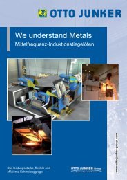
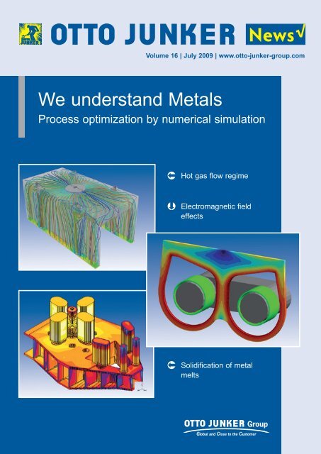
Volume 16 | July 2009 | www.otto-junker-group.com<br />
We understand Metals<br />
Process optimization by numerical simulation<br />
� Hot gas flow regime<br />
� Electromagnetic field<br />
effects<br />
� Solidification of metal<br />
melts<br />
News √
Contents<br />
News 2<br />
� Statement of the Management<br />
� Uwe Zulehner – new Managing Director<br />
of INDUGA<br />
Innovation 3/4<br />
� Innovative strip flotation furnace – optimization<br />
based on numeric and physical flow<br />
simulation<br />
� Successful long-term cooperation with<br />
RWTH Aachen's Institute of Industrial<br />
Furnace Engineering (IOB)<br />
Equipment technology ...<br />
Iron and steel 5/6<br />
� Use of numeric simulation to prevent<br />
molten metal splatter in coreless<br />
induction furnaces<br />
� Newly founded Zeitzer Guss <strong>GmbH</strong> uses<br />
OTTO JUNKER melting equipment<br />
light metal 7/8<br />
� One more OTTO JUNKER system for ELVAL<br />
� Lambda control – active fuel control for billet<br />
heaters saves energy and the environment<br />
Copper 9/10<br />
� Assuring the safety of controlled atmospheres<br />
– continuous strip annealing lines<br />
with controlled atmospheres containing<br />
up to 25 % H 2<br />
� INDUGA to supply brass pouring furnace<br />
production ...<br />
High grade steel foundry 11<br />
� Numerical simulation – the modern tool of<br />
foundry operators<br />
Topic 12<br />
� Many years of experience plus advanced<br />
simulation methods ensure success<br />
Imprint<br />
publisher: OTTO JUNKER <strong>GmbH</strong><br />
Jägerhausstraße 22, D-52152 Simmerath<br />
Editor: Dr. Dietmar Trauzeddel<br />
photography: OTTO JUNKER Group Archiv, INDUGA,<br />
Zeitzer Guss <strong>GmbH</strong><br />
layout: Atelier Beißel, Schmithofer Straße 200, 52076<br />
Aachen, Telefon: 0800 / 54 64 000 20<br />
publication interval: six-monthly<br />
If you have any questions regarding the contents<br />
of “OTTO JUNKER NEWS“ please call:<br />
Dr. Dietmar Trauzeddel, OTTO JUNKER <strong>GmbH</strong>,<br />
Phone: +49 2473 601 342.<br />
Reproduction of this publication, in whole or in part,<br />
is subject to the explicit prior permission of the editors.<br />
2<br />
Dear Customers and Business Partners,<br />
Dear Staff Members,<br />
Crucial sectors of the industry – like<br />
metalworking industry, machinery &<br />
equipment manufacturing and the automotive<br />
industry – are currently experiencing<br />
the impacts of a severe crisis all<br />
around the globe.<br />
Above and beyond the need to cope with<br />
the downturn in business financially,<br />
structurally and economically<br />
at present, setting the<br />
right strategic course for the<br />
future is a matter of great<br />
consequence as well.<br />
Apart from setting up our<br />
business processes to efficiently<br />
match an appropriate<br />
level of business volume, it<br />
is the development of new technology<br />
that forms the basis and the driving force<br />
for a long-term success of our company.<br />
This has been true for more than 85 years<br />
– ever since our company was founded –<br />
and will hold true in the time to come. It is<br />
indeed part of our company philosophy<br />
to shape competition by offering out-<br />
standing<br />
prices.<br />
technology at reasonable<br />
This innovation is driven by the expertise<br />
of our staff, and powered by our profound<br />
comprehension of technical and commercial<br />
requirements, as well as by the close<br />
contact to our customers.<br />
An important tool we are<br />
using today is numerical<br />
simulation: With suitable formulation<br />
of boundary conditions,<br />
numerical models form<br />
the basis for the design of<br />
concrete industrial solutions<br />
– theory forms the basis of<br />
professional practice.<br />
Have a look at some interesting examples<br />
in the present <strong>Junker</strong> News.<br />
Sincerely,<br />
Hans Rinnhofer<br />
Uwe Zulehner – new Managing Director of INDUGA<br />
Dipl.-HTL-Ing. Uwe Zulehner has been<br />
appointed Managing Director of INDUGA<br />
Industrieöfen und Giesserei-Anlagen <strong>GmbH</strong><br />
& Co. KG in Cologne with effect from 1st July<br />
2009. He is responsible for Sales and<br />
Engineering of the company that has been<br />
associated with OTTO JUNKER <strong>GmbH</strong> since<br />
early 2006. In this capacity he will run the<br />
business of INDUGA together with Markus<br />
Schmidt, Chief Commercial Officer of the<br />
company.<br />
Uwe Zulehner studied engineering at the<br />
Höhere Technische Lehranstalt für Bergbau<br />
und Metallurgie in Leoben/Austria.<br />
He started his industrial career in 1997 as a<br />
technical assistant in the melting operation<br />
of Breitenfeld Edelstahl in Mitterdorf/Austria.<br />
From 1998 till 2001 he was Marketing and<br />
Product Manager for functional refractories<br />
with the focus on steel converters at RHI<br />
Refractories AG in Vienna/Austria. Another<br />
milestone in his professional life was his<br />
engagement in the copper melting plant<br />
division of MAERZ-Gautschi Industrieofenanlagen<br />
<strong>GmbH</strong> with its headquarters in<br />
Düsseldorf/Germany from 2001 till 2007,<br />
where he started as Sales Manager and then<br />
advanced to the General Manager of the<br />
copper business unit. It was in this period<br />
that he published papers dealing with industrial<br />
furnace manufacture for secondary<br />
copper refinement and two patents were<br />
granted. During his time with MAERZ-<br />
Gautschi Mr. Zulehner spent three years<br />
together with his family in Brisbane/Australia<br />
running the international business.<br />
Before joining us, Mr. Zulehner was working<br />
with the Küttner Group as Director of Küttner<br />
Non Ferrous <strong>GmbH</strong> in Essen, Germany.<br />
'I look forward to joining Induga and despite<br />
the currently difficult overall market situation
OTTO JUNKER Innovation<br />
Innovative strip flotation furnace – optimization based on<br />
numeric and physical flow simulation<br />
This article describes the development of a new type of strip<br />
flotation furnace realized in close cooperation with the<br />
Technical University of Aachen (RWTH). The aim of this<br />
development was to design a furnace capable of handling<br />
higher temperatures and thicker strip material than its<br />
predecessors.<br />
Maintaining the strip afloat in the furnace requires a specific total<br />
outlet pressure from the nozzle system. This outlet pressure<br />
is generated by means of fans. Evidently, thicker strip needs<br />
higher pressures to build up an adequate supporting gas<br />
cushion. Moreover, the gas flow velocity and dynamic pressure<br />
essentially determine the system's power consumption. Since<br />
the high pressure needed to convey more heavy-gauge strip<br />
will tax the fans to the limits of technical feasibility, a different<br />
solution had to be found. The basic idea was to arrange two fans<br />
in series in the manner known, e.g., from pump technology.<br />
For the application on hand, a configuration was selected<br />
with two fans for the bottom nozzle array and one fan for the<br />
top nozzle array, cf. Fig. 1. The advantage of this design lies<br />
in the fact that the top and bottom sections of the furnace<br />
– i.e., the nozzle systems – are mutually independent. This<br />
creates more leeway for ensuring strip stability, etc.<br />
I shall endeavour<br />
to do this job for<br />
the best of the<br />
company and<br />
staff of INDUGA<br />
and the OTTO<br />
JUNKER group.<br />
My first priority is placed on sustainable<br />
strengthening of our position in the established<br />
and traditional fields of our business<br />
and also on establishing, together with our<br />
staff, a strong foothold of Induga as a technology<br />
partner to the copper industry.<br />
The key to a trusting and lasting successful<br />
cooperation in my opinion is first of all the<br />
personal contact to customers, full understanding<br />
of requirements to be met by our<br />
equipment as well as our after-sales service<br />
and, of course, a consistently high product<br />
quality.' says Uwe Zulehner.<br />
The upper fan draws protective atmosphere from the furnace<br />
chamber and blows it towards the second fan. With the pressure<br />
upstream of the second fan thus increased, the second fan<br />
merely needs to boost this pressure marginally to achieve the<br />
pressure level required at the nozzle array. In order to examine<br />
Successful long-term cooperation with RWTH<br />
Aachen's Institute of Industrial Furnace<br />
Engineering (IOB)<br />
What began as a pooling of efforts on<br />
selected development projects nearly<br />
10 years ago has by now evolved into a<br />
close and extensive collaboration. The<br />
objectives jointly pursued by the partners<br />
are to further optimize existing equipment<br />
designs, develop tailor-made solutions<br />
addressing specific customer needs, and<br />
generate innovative product ideas.<br />
All activities are regularly reviewed in the<br />
so-called steering committee, where IOB<br />
staff headed by Prof. Dr. Herbert Pfeifer<br />
and the experts and executives from our<br />
Heat Treatment Equipment division meet<br />
for presentations and discussions. Many<br />
new ideas have been born here.<br />
Once a new task has been defined, the<br />
Fig. 1: Solution with two fans arranged in series<br />
IOB will usually conduct computer-based<br />
simulations on CFD models. If necessary,<br />
test rigs will be built to validate results and<br />
improve the numeric models on the basis<br />
of practical findings.<br />
The sucess of this cooperation is attested<br />
by a number of equipment designs which<br />
have emerged from these projects and<br />
define the "state of the art" today. Examples<br />
deserving particular mention here<br />
include the energy-efficient flow management<br />
and heating systems employed in<br />
the thermal treatment of aluminium semifinished<br />
products and high-temperature<br />
copper strip processing.<br />
Günter Valder (+49 2473 601 328)<br />
3
4<br />
News<br />
OTTO JUNKER Innovation<br />
the potential of this solution approach, extensive numeric flow<br />
simulations were carried out. The equipment configuration with<br />
two fans in series was then progressively adapted to reflect the<br />
simulation results.<br />
Fig. 2 illustrates the system flow situation before and<br />
after the optimization (left picture). A flow bubble on the<br />
discharge side of the second fan and uneven flow at the<br />
system outlet are evident here. These shortcomings were<br />
removed through design improvements.<br />
Similar investigations were conducted for the pressure<br />
distribution within the fan system. As anticipated, the potential for<br />
increasing the pressure output was confirmed by the numeric<br />
simulation. For further studies it was decided to build a 1:1 scale<br />
cold model. Using this cold model, a physical flow simulation<br />
was then conducted. The cold model results were transferred to<br />
Fig. 2: Flow pattern before and after optimization<br />
Standard Compact Furnaces<br />
(MFT SC) – Development of a new<br />
generation of medium-frequency<br />
coreless systems is now complete<br />
The new furnace generation is aimed at<br />
applications in the medium power<br />
range. Its development was based on<br />
the expertise gained with many<br />
successful OTTO JUNKER mediumfrequency<br />
melting systems.<br />
The entire furnace design has been<br />
reviewed and optimized with the aid of<br />
advanced computing and numerical<br />
simulation methods.<br />
One main characteristic of this newgeneration<br />
equipment is its power<br />
saving and cost-efficient design.<br />
Capacities range from 2 to 6 tonnes<br />
(relating to cast iron). The electrical<br />
power input ranges from 1 to 4.8 MW.<br />
Along with many improvements in<br />
detail, a special melt processor with<br />
touch screen operation (M2F Touch<br />
the real-life furnace with the aid of known similarity theories<br />
(Reynold, etc.).<br />
Next, the characteristic curves of the furnace and of the two fans,<br />
as well as of the overall system, were measured and reconciled<br />
with the numeric simulation results.<br />
The findings derived from these investigations formed the basis<br />
for the design and manufacture of the innovative horizontal strip<br />
flotation furnace.<br />
The new furnace type was successfully commissioned at a<br />
leading manufacturer of copper semi-finished products,<br />
confirming the success of this development effort (Fig. 3).<br />
Fig. 3: The new type of strip flotation furnace<br />
Hansjörg Hoppe (+49 2473 601 284)<br />
Günter Valder (+49 2473 601 328)<br />
Screen) has been incorporated.<br />
With design now complete, sales of the<br />
new furnaces have commenced as of<br />
now.<br />
If you have any questions regarding<br />
the new furnace generation, please<br />
do not hesitate to get in touch.<br />
Your contact is Mr. Donsbach<br />
(+49 2473 601 207).
EqUIpMENT TECHNOlOgY Cast iron & steel<br />
Use of numeric simulation to prevent molten metal splatter<br />
in coreless induction furnaces<br />
On high-powered medium-frequency furnaces (approx.<br />
1,000 kW per tonne of furnace capacity) used for melting<br />
cast iron, metal spatter from the bath surface will occasionally<br />
be observed in the melt superheating phase.<br />
This phenomenon has been found to occur mainly when the<br />
furnace is full, i.e., at bath levels significantly above the top<br />
edge of the induction coil. One cause of such metal splatter<br />
is the boiling reaction that is a function of temperature and<br />
carbon and silicon concentrations of the melt.<br />
C + O � {CO}<br />
2C + (SiO 2 ) � Si + 2{CO}<br />
This CO gas formation may set in quite vigorously as soon as<br />
the boiling temperature is reached, particularly with thin-walled<br />
or rusty charge material which drives up melt oxygen levels.<br />
To gain a more accurate understanding of this process that will<br />
help in devising countermeasures, the energy, heat and material<br />
transfer phenomena taking place inside a medium-frequency<br />
furnace were studied in greater detail with the aid of coupled<br />
numeric flow and temperature field computing.<br />
It was found that high flow velocities in the upper part of the<br />
crucible and the presence of a pronounced meniscus can<br />
prevent the occurrence of metal splatter.<br />
Presumably, under normal conditions, the CO bubbles formed in<br />
the melt are dragged away by the strong bath flow, escaping into<br />
the atmosphere via the pronounced meniscus. Permanent melt<br />
degassing will thus take place without any interference by metal<br />
splatter.<br />
If, on the other hand, the melt is prevented from continuously<br />
degassing in this manner, larger gas bubbles will form and will<br />
ultimately develop enough buoyancy to rise abruptly to the<br />
surface which they will then penetrate with force, causing the<br />
melt to splatter.<br />
The correctness of this description is confirmed by tests and<br />
observations made on coreless induction furnaces in several<br />
foundries.<br />
The study has laid the groundwork for the creation of designs<br />
and operating regimes for coreless induction furnaces whereby<br />
metal splatter from high-oxygen melts can be reduced.<br />
In planning new installations, the furnace rating, operating<br />
frequency and coil arrangement can thus be optimized accordingly.<br />
It is also possible to run the furnace at a lower frequency<br />
in the superheating phase through the use of a frequency<br />
changeover feature (multi-frequency technology). This will result<br />
in a more pronounced meniscus and more vigorous surface flow,<br />
thus preventing molten metal splatter.<br />
Coreless induction furnace with pronounced meniscus and high<br />
melt flow velocity (Left: Calculation of the flow velocity in m/sec<br />
Right: Calculation of the temperature field in °C)<br />
A similar challenge is encountered in melting down galvanized<br />
steel scrap, where the problem lies in the associated formation<br />
of zinc vapour bubbles in the melt. Here, too, a "custom" control<br />
of the bath movement can help in the management of outgassing<br />
phenomena.<br />
Wilfried Schmitz (+49 2473 601 441)<br />
News<br />
Another OTTO JUNKER channel furnace for an<br />
Italian foundry<br />
Fonderia Corrà, a renowned foundry based in Thiene/Italy,<br />
has ordered an 85-tonne channel-type induction furnace<br />
system from OTTO JUNKER for use in the company's<br />
existing cupola melting operation. Molten iron is to be<br />
continuously transferred from the cupola to the holding<br />
furnace via a system of launders. The channel-type furnace<br />
has an overall capacity of around 100 tonnes and is<br />
powered via a 1000 kW IGBT converter system. This is<br />
enough to superheat 21.2 tonnes of liquid iron by 100 K per<br />
hour. A JOKS melt processor, acting in conjunction with a<br />
precise weight sensing system, ensures an accurate<br />
temperature and process management. Work is currently<br />
proceeding at full speed to complete the system.<br />
Its delivery is scheduled for July of this year.<br />
5
6<br />
EqUIpMENT TECHNOlOgY Cast iron & steel<br />
Newly founded Zeitzer Guss <strong>GmbH</strong> uses OTTO JUNKER<br />
melting equipment<br />
The successful company Silbitz guss<br />
gmbH established a new foundry for<br />
the production of large hand-moulded<br />
castings of up to 30 metric tonnes unit<br />
weight in Zeitz, germany. These<br />
castings are primarily used in the<br />
energy field (power stations/wind<br />
power plants). Only 20 km from the<br />
company's headquarters, an all-new<br />
foundry was erected on the premises<br />
of ZEMAg Zeitz, a former company<br />
with a very long tradition.<br />
The melting plant was ordered from OTTO<br />
JUNKER mid-2008 and successfully commissioned<br />
in April this year.<br />
The formal inauguration ceremony for the<br />
new foundry was solemnly conducted by<br />
the two managing directors, Dr. Wolfgang<br />
Maruschky and Dr. Frank Göttert, on<br />
June 25, 2009. Saxony-Anhalt's Minister-<br />
President, Professor Dr. Wolfgang Böhmer,<br />
pushed the starting button of the new<br />
furnace plant after the first pour had been<br />
initiated by Dr. Göttert following the<br />
tradition.<br />
The new 25-tonne furnace in action<br />
Solemn inauguration of the new foundry on 25 th June 2009<br />
The foundry is equipped with a<br />
25-tonne medium-frequency melting<br />
furnace plant. With its electrical power<br />
rating of 6,000 kW, the unit provides a<br />
melt output of 11.5 tonnes/hour. The<br />
furnace itself has a power consumption<br />
of 505 kWh/t at a melt temperature<br />
of 1,500 °C.<br />
The furnace features a back-tilting system<br />
and a deslagging spout to facilitate the<br />
slag removal operation.<br />
An additional slag gripper has likewise<br />
been integrated. Advanced exhaust hoods<br />
with bidirectional tilting action ensure a full<br />
extraction of furnace gases and dusts.<br />
The weighing system supplies all data<br />
needed by the JOKS melting processor<br />
to control the power input and avoid<br />
overheating at any point of the process<br />
cycle.<br />
Our scope of delivery further com-<br />
prised a longitudinally<br />
movable charging chute<br />
plus the entire water recooling<br />
system. The latter is<br />
equipped with separate<br />
systems for the furnace<br />
circuit and the switchgear<br />
circuit.<br />
The furnace circuit has<br />
a glycol-free air-to-water<br />
cooler developed by OTTO<br />
JUNKER.<br />
Jörg Andrejewski<br />
(Tel. +49 2473 601 208)
EqUIpMENT TECHNOlOgY Light metal<br />
One more OTTO JUNKER system for ELVAL<br />
At the Inofita rolling mill operated by<br />
ElVAl, the greek aluminium producer,<br />
several OTTO JUNKER furnace<br />
systems have been successfully in<br />
service for years. The company's<br />
equipment pool comprises two chamber<br />
furnace systems for annealing<br />
strip coils, a cooling chamber and<br />
charging machine as well as two<br />
pusher furnaces for preheating and<br />
homogenizing rolling ingots. In the<br />
spring of 2009, OTTO JUNKER was<br />
awarded the contract for supply of an<br />
additional chamber furnace for the<br />
heat-treatment of strip coils.<br />
As the new chamber furnace will supple-<br />
ment the existing production environment,<br />
it is designed to be loaded and discharged<br />
via the present charging machine. In the<br />
same way, the existing cooling chamber<br />
will also serve the new furnace.<br />
As the new unit is intended to heattreat<br />
strip of varying aluminium alloy compositions<br />
and thicknesses in the 0.2 to<br />
12.7 mm gauge range, it must provide the<br />
Existing OTTO JUNKER furnace at ELVAL<br />
associated flexibility. Thus, annealing<br />
temperatures may range from 150 to<br />
580 °C at furnace throughputs of between<br />
2.4 and 4.4 tonnes/hr.<br />
The furnace can be charged with 3 jumbo<br />
coils (of up to 2.6 m in diameter), or 4<br />
standard coils, up to a maximum charge<br />
weight of 90 tonnes. As an indirect natural<br />
gas-fired chamber-type furnace it is<br />
designed to operate both under protective<br />
nitrogen atmosphere or under air. It is<br />
divided into three fan sections, with two<br />
recuperative radiant tube burners per<br />
section. The fans are arranged in the<br />
furnace roof; heating ducts with integrated<br />
double-P shaped radiant tubes are<br />
mounted to the side of the useful<br />
chamber.<br />
The furnaces are equipped with the<br />
proven nozzle array to produce short<br />
heat-up times and a uniform temperature<br />
distribution. The swirl nozzle system<br />
with its star-shaped configuration of slot<br />
nozzles plus an array of three frequencycontrolled<br />
recirculation fans ensure a<br />
rapid and uniform heating process with<br />
minimized energy input. As a result, the<br />
furnace can be run in higher temperature<br />
regimes without risking local overheating<br />
of the coils. The coil face temperature is<br />
monitored by press-on thermocouples of<br />
a new design, so that even a charge<br />
comprising differently sized coils can be<br />
uniformly heated.<br />
Temperatures are controlled separately<br />
for the right- and left-hand side of each<br />
fan section, so that a total of 6 independent<br />
control zones is available.<br />
In conjunction with the high-convection<br />
heating principle, this design provides a<br />
± 5 K control accuracy in the 150 - 580 °C<br />
load temperature range.<br />
Work on the detailed engineering of<br />
this furnace is currently proceeding at<br />
full speed. Its delivery to the customer<br />
is scheduled for the end of this year.<br />
Higher productivity despite lower<br />
energy consumption were the key arguments<br />
in favour of OTTO JUNKER.<br />
Bernd Deimann (Tel. +49 2473 601 241)<br />
7
8<br />
EqUIpMENT TECHNOlOgY Light metal<br />
Lambda control – active fuel control for billet heaters<br />
saves energy and the environment<br />
The first air/gas control for gas-fired<br />
industrial furnaces has stood the test<br />
under real operating conditions.<br />
After several months of commercial<br />
multi-shift operation on a gas-fired<br />
rapid heater for aluminium extrusion<br />
billets operated by Hydro company in<br />
Uphusen, germany, the system has<br />
delivered very positive results.<br />
gas savings in the order of more than<br />
10 % were achieved easily. Of course,<br />
these savings could also be translated<br />
into increased throughput capacity.<br />
This innovative development takes into<br />
account the ever-changing variables of<br />
gas/air mixing, which have so far been<br />
neglected.<br />
Ambient conditions, air temperature and<br />
pressure, humidity, gas quality, and actual<br />
output requirements are parameters<br />
measured and evaluated for furnace<br />
control.<br />
HIGH-TEC Engineering <strong>GmbH</strong> has<br />
focused its development efforts in the field<br />
of gas-fired industrial furnaces on gas<br />
mixers, burner nozzles and this lambda<br />
control, which has already been patented.<br />
OTTO JUNKER <strong>GmbH</strong> is the exclusive<br />
contracting partner for application, sales<br />
and service. Joint trials and projects have<br />
paved the way to the leading market<br />
position we hold.<br />
It is only through the newly developed<br />
applications in 'open' gas-firing systems<br />
that lambda control, which is known from<br />
car engines, can now be used in this field.<br />
Comparative measurements prior to and<br />
after installing the lambda control have<br />
confirmed improvements, or energy<br />
savings, amounting to more than 10 % on<br />
average.<br />
The only modification required (for each<br />
furnace control zone) is the installation of<br />
the pilot burner with integrated lambda<br />
Temperature absolute & gradient<br />
probe for measurement of the current<br />
values, a motor-controlled gas valve and<br />
the integration into the furnace control<br />
system.<br />
We have achieved the said improvement<br />
by installing the lambda control system,<br />
new burner nozzles and mixers, of course<br />
perfectly tailored to suit the overall<br />
concept.<br />
Key improvements through use of the<br />
lambda control:<br />
� stable and uniform combustion<br />
quality<br />
� optimum adjustment of furnace<br />
control to partial and full load<br />
conditions<br />
� reduction of energy consumption<br />
or increase of furnace throughput<br />
� improved and constant exhaust gas<br />
quality through optimum combustion<br />
There is a proper economic relationship<br />
between the cost of this modification<br />
and the result thereof – not even<br />
taking into consideration the emission<br />
reductions achieved.<br />
Oliver Flamm (+49 2473 601 211)<br />
News<br />
Third casting furnace for Fata<br />
S.p.A. (Italy)<br />
For casting and holding of liquid<br />
aluminium from the electrolysis<br />
OTTO JUNKER was awarded a<br />
contract to supply another reverberatory<br />
furnace out of the<br />
THERMCON product range.<br />
The gas-fired furnace has a content<br />
of 66 tonnes and is equipped with a<br />
hydraulic tilting mechanism. The<br />
delivery also includes a hydraulically<br />
activated crucible tilting stand for<br />
pouring the liquid metal into the<br />
furnace and a liquid metal launder<br />
system with a laser level controller<br />
which ensures a continuous casting<br />
rate of max. 20 tonnes per hour.<br />
The successfully operating furnaces<br />
supplied earlier were crucial for<br />
FATA's decision to award OTTO<br />
JUNKER this contract.
EqUIpMENT TECHNOlOgY Copper<br />
Assuring the safety of controlled atmospheres – continuous<br />
strip annealing lines with controlled atmospheres containing<br />
up to 25 % H 2<br />
OTTO JUNKER gmbH is the leading<br />
manufacturer of continuous strip<br />
processing lines for copper and its<br />
alloys.<br />
A broad spectrum of complete OTTO<br />
JUNKER furnaces and equipment designs<br />
matching diverse customer needs is<br />
available for the continuous processing of<br />
ultra-thin to heavy-gauge copper and<br />
copper-alloy strip in applications ranging<br />
from recrystallization and solution<br />
annealing to surface treatment.<br />
Strip in the 0.05 to 2.0 mm thickness<br />
range is annealed in strip flotation furnaces<br />
at temperatures up to 850 °C<br />
(within limits up to 900 °C).<br />
The continuous passage of the strip<br />
through the flotation furnace makes<br />
for a defined short annealing cycle<br />
capable of providing a homogeneous<br />
strip temperature distribution and<br />
hence, uniform material properties.<br />
In order to meet today's increased<br />
production technology and quality<br />
demands on specific product types, OTTO<br />
JUNKER also supplies strip flotation<br />
furnaces operating under a controlled<br />
hydrogen/nitrogen atmosphere of up to<br />
25 % H2 in N2 .<br />
Major benefits of a 25 % H2 in N2 atmosphere<br />
over conventional equipment<br />
running with max. 5 % of hydrogen, are<br />
the superior convective heat transfer,<br />
markedly increased reduction (i.e., antioxidation)<br />
performance, and the much<br />
cleaner material surface obtained.<br />
Aside from these production engineering<br />
benefits, however, the combustion and<br />
explosion characteristics of a 25 % H2 atmosphere pose exacting requirements<br />
on furnace design, mainly in terms of<br />
explosion prevention technology.<br />
In close cooperation of OTTO JUNKER<br />
and TÜV Nord, a hazard assessment has<br />
been developed and refined over a number<br />
of years. This hazard assessment<br />
takes into account the various furnace<br />
conditions as well as the substance<br />
characteristics of the protective gas, inert<br />
gas and air atmospheres across all<br />
possible concentration and temperature<br />
ranges. The result is an explosion protection<br />
concept incorporating indispensable<br />
explosion-protection measures as part of<br />
the fundamental design of the strip<br />
flotation furnace.<br />
This explosion protection concept is basically<br />
achieved through effective sealing of<br />
the furnace from the ambient atmosphere,<br />
the general prevention of potentially<br />
explosive areas, and the separation between<br />
air and the 25 % H2 in N2 atmosphere<br />
(inertising concept). The approach<br />
is pursued further at the level of the<br />
control and analytical system design<br />
(equipment concept). Here, key aspects<br />
include the configuration and evaluation<br />
of the systems monitoring the oxygen and<br />
furnace chamber pressures. All equipment<br />
is selected and configured in line<br />
with the safety category stipulated in the<br />
explosion protection concept.<br />
Continuous strip processing line with furnace unit<br />
The latter is rounded out by an on-site<br />
acceptance process in which the<br />
system's protective features are<br />
checked on site by TÜV Nord.<br />
Consequently, a fully tested and safe<br />
installation will be handed over to the<br />
customer. Most recently, the furnace control<br />
configuration and interfacing with peripheral<br />
equipment have been based on<br />
the use of a fail-safe Siemens automation<br />
system. The advantages of this control<br />
technology lie in the fact that programmed<br />
protective functions can be simulated prior<br />
to commissioning, so that start-up times<br />
will be markedly reduced. Less hardwired<br />
programming of the type known from conventional<br />
safety technology will further<br />
accelerate the commissioning process.<br />
System diagnosis features and an online<br />
remote access capability enable rapid fault<br />
identification and troubleshooting. The<br />
ability to adapt software and control<br />
systems flexibly to individual process<br />
conditions and furnace designs, bearing in<br />
mind the requirements of the hazard<br />
assessment, is likewise highly beneficial.<br />
9
10<br />
EqUIpMENT TECHNOlOgY Copper<br />
Thanks to the concept outlined above,<br />
OTTO JUNKER equipment embodies a<br />
high degree of automation, meets<br />
exacting process safety standards,<br />
and is noted for greatly reduced failure<br />
probabilities.<br />
Two strip flotation furnaces for operation<br />
with a protective atmosphere of up to 25 %<br />
H2 in N2 – both embodying the new<br />
control system – are currently being<br />
commissioned.<br />
INDUGA to supply brass pouring furnace<br />
As part of an extensive upgrade of its<br />
vertical-type continuous caster, DIEHl<br />
Metall placed an order with INDUgA in<br />
late January 2009 for a channel-type<br />
induction furnace for holding and<br />
pouring of brass.<br />
The new forehearth-type pouring furnace<br />
replaces the existing furnace having<br />
reached the end of its life. The new installa-<br />
Factory assembly of the pouring furnace<br />
tion will have an overall capacity of<br />
20 tonnes and is to be heated by a<br />
channel inductor with a rated output of<br />
500 kW. The order also comprises a new<br />
electrical powerpack and advanced<br />
furnace control equipment.<br />
The furnace can be hydraulically tilted<br />
and rolled back on a bogie to perform<br />
setup or maintenance work on the<br />
continuous caster.<br />
OTTO JUNKER has sold 6 lines using<br />
a high-hydrogen protective atmosphere<br />
technology at the global level<br />
since 2000, and all are operating<br />
successfully.<br />
Jörg Neuhaus (+49 2473 601 364)<br />
Molten metal is provided by three coreless-type<br />
chip melting furnaces arranged<br />
one three sides of the pouring furnace.<br />
The pouring furnace is filled through three<br />
filling gates.<br />
The commissioning of the pouring<br />
furnace will be in the 4th quarter of<br />
2009.<br />
Alejandro Hauck (+49 221 95757 24)
pRODUCTION High grade steel foundry<br />
Numerical simulation – the modern tool of foundry operators<br />
About 30 years ago prof. Dr. Dr. h.c. peter Sahm laid the<br />
foundations for numerical simulation at the Foundry<br />
Institute of the Technical University RWTH Aachen.<br />
In these early days, however, operators smiled at this condescendingly<br />
with statements like "look at these computer<br />
casters".<br />
Very soon, however, the tremendous benefits of this technology<br />
were realized in foundry circles. Expensive trials<br />
for optimum design of castings could be replaced with<br />
numerical simulation.<br />
Time savings also were significant, since pattern changes<br />
and optimization steps no longer needed to be done on the<br />
pattern or mould itself but directly on the computer.<br />
The high-grade steel foundry of OTTO JUNKER <strong>GmbH</strong> recogniz-<br />
ed this great potential at a very early stage and supported the<br />
development of this technology by way of research projects<br />
financed by the OTTO JUNKER Trust.<br />
Since as early as 1992 numerical simulation has been used successfully<br />
in our special-steel foundry. This tool is of paramount<br />
importance, especially for jobbing foundries operating on a contract<br />
basis. In the jobbing business, the numbers of castings to be<br />
produced are typically small and casting defects or expensive<br />
practical tests for casting design would render the job unviable<br />
economically.<br />
This is why numerical simulation is used to optimize intricate<br />
parts with high quality requirements prior to any real casting<br />
operation. The objective of numerical simulation is to translate<br />
theoretically determined casting and gating parameters into real<br />
life.<br />
A machine bed of approx. 2,300 kg casting weight is a typical<br />
example. We have optimized the mould filling (Fig. 1) and<br />
solidification behaviour (Fig. 2) of this casting by numerical simulation<br />
on the computer. Quality check of the prototype (Fig. 3)<br />
impressively confirmed the results of simulation.<br />
Numerical simulation offers a wide range of features in the<br />
preparation and design stages to ensure cost-efficient<br />
manufacture and high castings quality.<br />
Elmar Westhoff (Tel. +49 2473 601 400)<br />
Fig. 1: Simulation of mould filling as a function of temperature<br />
gradient<br />
Fig. 2: Simulation of solidification as a function of temperature<br />
gradient. Solidification simulation follows the mould filling situation.<br />
Bild Fig. 3: Maschinenbett Machine bed prototype – Prototyp<br />
11
TOPIC:<br />
Many years of experience plus advanced simulation<br />
methods ensure success<br />
The dynamic behaviour of liquid metal flows and hot gases,<br />
as well as the solidification of metals and the flux pattern of<br />
electromagnetic fields, have one thing in common – they are too<br />
complex to be theoretically described and captured with the aid<br />
of physical formulae alone.<br />
While a steady-state process may still be calculable, individual<br />
parameter changes in time may influence the overall system in<br />
ways which elude adequate and precise mapping.<br />
By developing a model which represents a mathematical<br />
abstraction of the system under investigation, the influence of<br />
individual parameters can be examined.<br />
In a simulation, this theoretical model is studied to gain insights<br />
into the real-life system.<br />
However, it should be borne in mind here that any mathematical<br />
model employed can only depict reality with more or less<br />
precision. A model necessarily involves simplification, and its<br />
results need to be interpreted accordingly. The findings derived<br />
from it must therefore be verified through investigations or<br />
OTTO JUNKER gmbH<br />
P. O. BOX 11 80 • D-52147 Simmerath<br />
Phone: +49 2473 601-0 • Fax: +49 2473 601-600<br />
measurements on scale models or in laboratory-level trials<br />
(so-called physical simulation) before they can be deemed<br />
valid.<br />
Through numeric simulation followed by validation of the computed<br />
results, one can progress from the more or less "empirical"<br />
fundamentals of furnace design and advance towards precise,<br />
optimized design solutions.<br />
At the same time, this approach creates the basis for designing<br />
high levels of safety and reliability into new applications, technical<br />
innovations and new developments, and into tomorrow's<br />
larger and more powerful furnace systems.<br />
Many time-consuming, expensive experiments on real-life<br />
equipment can thus be largely avoided.<br />
The same holds true for the technological preparation of product<br />
casting processes.<br />
Without simulation of the solidification cycle it used to be necessary<br />
to conduct multiple trial castings with different pouring<br />
system configurations and unfinished product designs before a<br />
reliable casting process was achieved. By simulating the solidification<br />
of the melt, it has become possible to optimize technological<br />
processes quickly and cost-efficiently.<br />
In the future, simulation will play an increasing role in industrial<br />
equipment planning and process optimization, as well as in<br />
training and instruction environments. Real-life applications also<br />
exist, e.g., for training operators and maintenance personnel.<br />
The experience, knowledge and skills accumulated by our<br />
staff over many years, combined with the benefits of numeric<br />
simulation and advanced computing techniques, guarantee the<br />
continuing optimization of OTTO JUNKER equipment and<br />
technology.<br />
Dietmar Trauzeddel (+49 2473 601 342)