Datasheet DB EN R-IB IL INC-IN-PAC - Bosch Rexroth
Datasheet DB EN R-IB IL INC-IN-PAC - Bosch Rexroth
Datasheet DB EN R-IB IL INC-IN-PAC - Bosch Rexroth

Create successful ePaper yourself
Turn your PDF publications into a flip-book with our unique Google optimized e-Paper software.
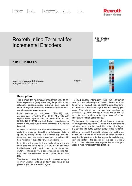
Electric Drivesand ControlsHydraulicsLinear Motion andAssembly Technologies Pneumatics Service<strong>Rexroth</strong> Inline Terminal forIncremental EncodersR911170488Edition 02R-<strong>IB</strong> <strong>IL</strong> <strong><strong>IN</strong>C</strong>-<strong>IN</strong>-<strong>PAC</strong>Input for incremental decoder3 digital 24V DC inputs03/2007DescriptionThe terminal for incremental encoders is used to determinepositions (lengths) or angular positions withrelatively operating encoder systems, i.e., it reads positionor angular information from incremental encoderswith square-wave signals.Both symmetrical encoders (RS-422) andasymmetrical encoders (5 V DC to 24 V DC) withsquare-wave signals can be connected to theR-<strong>IB</strong> <strong>IL</strong> <strong><strong>IN</strong>C</strong>-<strong>IN</strong>-<strong>PAC</strong> terminal. Rotary transducers orlength measuring systems with or without Z pulse canbe read.In order to increase the operational reliability all encoderinputs are monitored for cable breaks. Using aspecial operating mode, the terminal supports distanceencoded incremental encoders, which enablehoming to be reduced to very small distances.In addition to the input for the encoder signals, the terminalalso has three digital 24 V DC inputs, one inputfor the home position switch, and two inputs for limitswitches. Thus 2 or 3-wire sensors can be connected.Input I3 can also be used as an "open collector" output.The terminal records the position values using acounter, which counts up or down depending on thephase angle of the A and B signals.To read usable information from the positioningcounter after switching it on, it must be set to a definedvalue on a particular point of the axis. The terminalrequires a reference signal for this homing process.This signal can be set via Localbus orgenerated by one of the digital inputs. Either the signalat the home position switch input or one of the twolimit switch signals can be used.To increase the accuracy of the homing function,"Homing on the edge at the Z pulse input" can also beselected on the terminal in addition to the "Homing onthe edge at the home position switch input" function.When homing with Z signal it is important that the encoderand the reference mark are adjusted in such away that the position of the home position switch edgeis in the center of the positions of the edges at the Zinput. In the delta counting register the terminal providesa read function for this distance.
2/18 <strong>Bosch</strong> <strong>Rexroth</strong> AG | Electric Drives R-<strong>IB</strong> <strong>IL</strong> <strong><strong>IN</strong>C</strong>-<strong>IN</strong>-<strong>PAC</strong> | Data Sheetand ControlsFeatures• Three inputs for home position switch inputs orlimit switch inputs• Diagnostic and status indicatorsApplicationsThe following encoder types can be connected:• Encoder with symmetrical data lines accordingto EIA standard RS-422• Encoder with asymmetrical data lines(push/pull 10 V to 30 V)• Distance encoded incremental encoder(quasi-absolute encoder)• Encoder with 5 V or 24 V voltage supply• Linear encoder• Rotary transducerThis data sheet is only valid inassociation with the applicationdescriptions for the <strong>Rexroth</strong> Inlinesystem (see "Documentation" onpage 3).Make sure you always use the latestdocumentation. It can be downloadedat www.boschrexroth.com.
Data Sheet | R-<strong>IB</strong> <strong>IL</strong> <strong><strong>IN</strong>C</strong>-<strong>IN</strong>-<strong>PAC</strong> Electric Drives | <strong>Bosch</strong> <strong>Rexroth</strong> AG 3/18and ControlsOrdering DataProductDescription Type MNR Pcs./Pck.<strong>Rexroth</strong> Inline terminal for incremental encoders,complete with accessories (connectors and labeling fields)R-<strong>IB</strong> <strong>IL</strong> <strong><strong>IN</strong>C</strong>-<strong>IN</strong>-<strong>PAC</strong> R911308491 1DocumentationDescription Type MNR Pcs./Pck."Configuring and Installing the <strong>Rexroth</strong> Inline Product Rangefor <strong>IN</strong>TERBUS" application description„Automation Terminals of the <strong>Rexroth</strong> Inline Product Range“application descriptionDOK-CONTRL-<strong>IL</strong>-SYSPRO***-AW..-<strong>EN</strong>-PDOK-CONTRL-<strong>IL</strong>-SYS<strong>IN</strong>S***-AW..-<strong>EN</strong>-PR911317023 1R911317021 1For additional ordering data (accessories), please refer to the product catalog atwww.boschrexroth.com.Technical DataGeneral DataHousing dimensions (width x height x depth)24.4 mm x 120 mm x 71.5 mmWeight143 g (with connectors)Operating modeProcess data modeConnection method for sensors2 or 3-wire technologyConnection method for actuators2-wire technology, single-endedAmbient temperature (operation)-25°C … +55°CAmbient temperature (storage/transport)-25°C … +85°CPermissible humidity (operation/storage/transport) 10 % to 95 % according to D<strong>IN</strong> <strong>EN</strong> 61131-2Permissible air pressure (operation/storage/transport) 70 kPa ... 106 kPa (up to 3000 m above sea level)Degree of protection IP20 according to IEC 60529Protection class Class 3 according to VDE 0106, IEC 60536Connection data of Inline-connectorConnection methodspring-cage terminalsConductor cross-section 0.2 mm 2 to 1.5 mm 2 (solid or stranded), AWG 26-14InterfaceLocal bus interfaceTransmission SpeedR-<strong>IB</strong> <strong>IL</strong> <strong><strong>IN</strong>C</strong>-<strong>IN</strong>-<strong>PAC</strong>Power ConsumptionCommunications power U LCurrent consumption at U LPower consumption at U LI/O supply from U MCurrent consumption at U MThrough data routing500 kbps7.5 V70 mA, maximum525 mW24 V DC, typical340 mA, typicalSupply of the Module Electronics and I/O Through Bus Coupler/Power TerminalConnection methodThrough potential routingPower DissipationPower dissipation of the housing P HOU1.4 W, maximum(within the permissible operating temperature)
4/18 <strong>Bosch</strong> <strong>Rexroth</strong> AG | Electric Drives R-<strong>IB</strong> <strong>IL</strong> <strong><strong>IN</strong>C</strong>-<strong>IN</strong>-<strong>PAC</strong> | Data Sheetand ControlsDigital InputsNumber 3Input design According to <strong>EN</strong> 661131-2, type 1Definition of switching thresholdsSignal range lowSignal range highCommon potentialsNominal input voltage U <strong>IN</strong>Permissible rangeNominal input current for U <strong>IN</strong>Delay timePermissible cable length to the sensor-30 V DC ... +5 V DC15 V DC ... 30 V DCI/O supply, ground24 V DC-30 V < U <strong>IN</strong> < +30 V DC2.7 mA, typical
Data Sheet | R-<strong>IB</strong> <strong>IL</strong> <strong><strong>IN</strong>C</strong>-<strong>IN</strong>-<strong>PAC</strong> Electric Drives | <strong>Bosch</strong> <strong>Rexroth</strong> AG 5/18and ControlsEncoder Supply5 V Encoder SupplyVoltage rangeShort-circuit protectionCurrent carrying capacity24 V Encoder SupplyVoltage rangeShort-circuit protectionCurrent carrying capacity4.75 V ... 5.25 VElectronic and thermal250 mA, maximum19.2 V ... 30 VElectronic and thermal250 mA, maximumThe state of the encoder supplies (5 V/24 V) is indicated via two LEDs. If the internal voltagefor the encoder electronics fails or is overloaded, an I/O error is generated. This error isindicated by the diagnostic LED flashing at 2 Hz and transmitted to the controller board.Error Messages to the Higher-Level Control or Computer SystemFailure or overload of the encoder supplyYes, I/O error message sent to the controller boardNo encoder connectedYes, I/O error message sent to the controller boardWire break on an encoder cableYes, I/O error message sent to the controller boardElectrical Isolation/Isolation of the Voltage AreasThe electrical isolation of the logic level from the I/O area is ensured through the optocoupler.Common PotentialsThe 24 V main voltage, 24 V segment voltage, and GND have the same potential. FE is a separate potential area.Separate Potentials in the System Consisting of Bus Coupler/Power Terminal and I/O TerminalTest DistanceTest Voltage7.5 V supply (bus logic)/I/O 500 V AC, 50 Hz, 1 min.7.5 V supply (bus logic)/functional earth ground 500 V AC, 50 Hz, 1 min.24 V supply (I/O)/functional earth ground 500 V AC, 50 Hz, 1 min.Conformance With EMC Directive 89/336/EECNoise Immunity Test According to <strong>EN</strong> 61000-6-2Electrostatic discharge (ESD) <strong>EN</strong> 61000-4-2/IEC 61000-4-2 Criterion B6 kV contact discharge8 kV air dischargeElectromagnetic fields <strong>EN</strong> 61000-4-3/IEC 61000-4-3 Criterion BField strength: 10 V/mFast transients (burst) <strong>EN</strong> 61000-4-4/IEC 61000-4-4 Criterion BSupply lines: 2 kVSignal/data lines: 2 kVConducted interference <strong>EN</strong> 61000-4-6/IEC 61000-4-6 Criterion ATest voltage 10 VNoise emission of housing <strong>EN</strong> 55011 Class AApprovalsFor the latest approvals, please visit www.boschrexroth.com.
6/18 <strong>Bosch</strong> <strong>Rexroth</strong> AG | Electric Drives R-<strong>IB</strong> <strong>IL</strong> <strong><strong>IN</strong>C</strong>-<strong>IN</strong>-<strong>PAC</strong> | Data Sheetand ControlsLocal Diagnostic and Status Indicators,7 2, !1 + 1Fig. 1 Local diagnostic and status indicators" 8# 8$ ! ' + Des. Color MeaningD Green LED DiagnosticsON: Bus activeFlashing:0.5 Hz: Communications power present,bus not active2 Hz: Communications power present,bus active, I/O error4 Hz: Communications power present,terminal before the flashing modulefailed, terminal after the flashingmodule not part of the configurationframeOFF: Communications power present,bus not activeUP Yellow LED Positive direction of rotationON and Module counting upwards"DN" LEDOFF:OFF and Downtime"DN" LEDOFF:DN Yellow LED Negative direction of rotationON and "UP" Module counting downwardsLED OFF:OFF and"UP" LEDOFF:DowntimeZ Yellow LED Z signal In incrementalON: Z signalpresentOFF:Z signalnot activeencoders the encoder isset to Z signal.In rotary transducersthe LED flashes or ispermanently on (dependingon the speed).24V Green LED 24 V encoder supplyON: 24 V encoder supply presentOFF: 24 V encoder supply not present1, 2, 3 Yellow LED InputsON: The corresponding input is setOFF: The corresponding input is not set5V Green LED 5 V encoder supplyON: 5 V encoder supply presentOFF: 5 V encoder supply not presentFunction IdentificationOrange
Data Sheet | R-<strong>IB</strong> <strong>IL</strong> <strong><strong>IN</strong>C</strong>-<strong>IN</strong>-<strong>PAC</strong> Electric Drives | <strong>Bosch</strong> <strong>Rexroth</strong> AG 7/18and ControlsTerminal Point Assignment ! " ! " !!!!! !!!" ! """"! """" "! ###" #! $$$" $$ ! ' , !Fig. 2Inline terminal with appropriate connectorsTerminal Point Assignment for Shield Connector (1)TerminalPointSignalAssignmentSymmetrical EncoderTerminal Point Assignment for Connector (2)Asymmetrical Encoder1.1, 2.1 A, A Channel A, channel A inverted Channel A, free1.2, 2.2 B, B Channel B, channel B inverted Channel B, free1.3, 2.3 Z, Z Channel Z, channel Z inverted Channel Z, free1.4, 2.4 Shield Encoder cable shield Encoder cable shieldTerminal Signal AssignmentPoint3.1 I1 Input of limit switch 14.1 I2 Input of limit switch 23.2, 4.2 24 V 24 V encoder/limit switch supply3.3, 4.3 GND 0 V encoder/limit switch supply3.4 I3 Input for homing position switch or NPN output4.4 5 V 5 V encoder/limit switch supply3.5, 4.5 24 V 24 V encoder/limit switch supply3.6, 4.6 GND 0 V encoder/limit switch supply
8/18 <strong>Bosch</strong> <strong>Rexroth</strong> AG | Electric Drives R-<strong>IB</strong> <strong>IL</strong> <strong><strong>IN</strong>C</strong>-<strong>IN</strong>-<strong>PAC</strong> | Data Sheetand ControlsFunctionThe R-<strong>IB</strong> <strong>IL</strong> <strong><strong>IN</strong>C</strong>-<strong>IN</strong>-<strong>PAC</strong> is a terminal from the Inlineproduct range and is used to read position and angularinformation.Symmetrical or asymmetrical encoders can be connectedfor this.The evaluating logic of the terminal detects the directionof rotation of the encoder using the pulse trainand counts the pulses accordingly.The data width in the bus system is 32 bits. The <strong>IN</strong>register has seven bits available for status indicatorsand messages and 25 bits available for actual positionvalues. The OUT register has seven bits availablefor control commands and 25 bits available for settingthe reference point value (see "Process Data" onpage 14).If a symmetrical encoder without Z signalis used, input Z must be jumperedto 0 V (GND) and input Z must be jumperedto +5 V.If an asymmetrical encoder is used,input Z must be jumpered to 0 V (GND)and input Z remains open.The encoders must have push/pull outputsto ensure error-free operation ofthe monitoring mechanisms.When using encoders with high-siteswitches each encoder signal must beset to 0 V (GND) using a pull-down resistor(see Fig. 3 and Fig. 4 on page 9).I/O ErrorsThe terminal has the following monitoringmechanisms, which generate an I/O error message:• Monitoring the encoder power supply (5 V or24 V)If the encoder supply fails or is overloaded, anI/O error is triggered and a corresponding messagecode is generated.• Monitoring the encoder signalsThe differential signal of a symmetrical encodermust be greater than 0.5 V.An asymmetrical encoder must actively set theinputs, biased at 3 V using resistors, below 2.5 V(0-level) or above 3.5 V (1-level).If these conditions are not met, an I/O error istriggered and a corresponding message code isgenerated. These errors are caused by no encoderbeing connected, an asymmetrical encodernot being parameterized as an asymmetricalencoder or a wire break in an encoder cable.
Data Sheet | R-<strong>IB</strong> <strong>IL</strong> <strong><strong>IN</strong>C</strong>-<strong>IN</strong>-<strong>PAC</strong> Electric Drives | <strong>Bosch</strong> <strong>Rexroth</strong> AG 9/18and Controls- ? @ A H 1* 1 1 + 1) * H / , EJ H E C BJD A A ? @ A H I EC = IFig. 3Connection of asymmetrical encoders withpush/pull outputs$ ! ' ) - ? @ A H 1* 1 1 + 1) * H 9 EJ H E C BJD A A ? @ A H I EC = I/ ,Fig. 4$ ! ' ) Connection of asymmetrical encoders with high-site switch outputsPosition DetectionIn order to start position detection after switching onthe terminal, the control bits for the encoder type andthe evaluation of OUT process data OUT[0] are writtento the terminal. The terminal then starts positiondetection with a random value in the positioningcounter. As long as operating mode 0 ("Read actualposition value") is not exited the actual position valueonly gives relative position values (without homing).The control bits for the encoder type and evaluationmust remain set as long as position detection is carriedout. Changing the evaluation also requires newhoming.The terminal can only output an absolute positionvalue if homing has been carried out on the terminalbefore. The homing function is used to set the positioningcounter to the reference point value determinedby OUT process data OUT[0] on a specificpoint of an axis.This homing process can be carried out by setting thereference point via the local bus (operating mode 1).During this process, the axis remains as still as possibleor moves so slowly that the time delay, with whichthe signals are transmitted via the local bus, does notcause any major deviations.Dynamic homing is also possible. In many applications,a higher level of precision is achieved throughdynamic homing using a homing process.The R-<strong>IB</strong> <strong>IL</strong> <strong><strong>IN</strong>C</strong>-<strong>IN</strong>-<strong>PAC</strong> terminal provides five differenttypes of homing (operating modes 2 to 6) for dynamichoming. The terminal responds directly to theconnected limit switch or home position switch signalsor the Z signal (index pulse from the encoder) with ahardware circuit.
10/18 <strong>Bosch</strong> <strong>Rexroth</strong> AG | Electric Drives R-<strong>IB</strong> <strong>IL</strong> <strong><strong>IN</strong>C</strong>-<strong>IN</strong>-<strong>PAC</strong> | Data Sheetand ControlsHoming function sequence:1. Start homingThe reference point value is written to OUT[0]and OUT[1]. Next, homing is started by means ofwriting one of the control codes for operatingmodes 1 to 5 to OUT[0].If the terminal has already been homed the messagecode switches to "Device not homed".2. Wait for acknowledgment (status bit A)The time it takes to receive acknowledgmentvaries depending on the homing mode. In operatingmode 1, the acknowledgment bit (status bitA) appears immediately, in operating modes 2 to6 the time it takes depends on the distance to thereference point and the speed at which the axisruns during homing (see page 14).The "Homed" acknowledgment bit is present untilan error occurs or a new homing process is initialized.3. Read adjustment value (only for the homingtypes in operating modes 4 and 5)In operating modes 4 and 5, the delta value (adjustmentvalue) can be read in the "Actual positionvalue" data field. This value indicates thedistance between the position of the home positionswitch edge and the position of the Z pulse.This value is present in the "Actual position value"data field until switching to operating mode 0("Read actual position value"). Beginning fromthe Z pulse position the positioning counter internallystarts position detection.4. Switch back to "Read actual position value"Operating mode 0 ("Read actual position value")is selected in OUT[0]. The relevant positions canbe read from the "Actual position value" datafield in <strong>IN</strong>[0] and <strong>IN</strong>[1] (value range 0 to 2 25 ... 1).The output counter state corresponds to the incrementsof the overrun field and is present until switchingto operating mode 0 "000 bin " ("Read actual positionvalue"). After changing the operating mode, thecounter state is displayed beginning from the secondreference mark. The position corresponds to the positionbefore or after the determined field depending onthe counting and positioning directions.Homing for Distance-Encoded Linear EncodersIn addition to the counting tracks, distance encodedlinear encoders are provided with a reference marktrack with different increments. This results in fieldsbetween two reference marks, which differ in size.Each field only appears once in the linear system.In order to detect the absolute position in the systemonly two reference marks must be overrun.The process is carried out as follows (see Fig. 5 andFig. 6): The slide position is unknown. In set operatingmode 6 "110 bin " the slide is moved in any direction.When the slide reaches the first reference mark(Z) the internal counter is set to zero and the incomingincrements of the counting track are added.When the slide reaches the second reference markthe counter status determined between the two referencemarks is output and the internal counter is set tozero again. At the same time, the "Acknowledgment,device homed" message code is output.
Data Sheet | R-<strong>IB</strong> <strong>IL</strong> <strong><strong>IN</strong>C</strong>-<strong>IN</strong>-<strong>PAC</strong> Electric Drives | <strong>Bosch</strong> <strong>Rexroth</strong> AG 11/18and Controls, EI J= ? A A ? @ A @ E A = HA ? @ A H# # # # # # # # # # # # ## " ' # # " & # # " & # # " % # # ! " % 2 I EJE E C E F I EJEL A ? K JE C @ EHA ? JE 1 JA H = ? K JA H5 J= HJM EJD + K JA H F A H= JE C @ A $ > E) ? M A @ C A J@ A L E? A D A @ A I I = C A ? @ AEI @ EI F = O A @ = @ F I EJE E C ? K JA H : E ? HA A JI E ? HA A JI E ? HA A JI+ D = C E C J F A H= JE C @ A > E4 A = @ = ? JK = F I EJE L = K A = BJA HI J F EBHA G K EHA @+ K JA H ) ? JK = F I EJE L = K A@ EI F = O: E ? HA A JI E ? HA A JI # # @ A ?' $ D A N E ? HA A JI) ? JK = F I EJE L = K A @ EI F = O ' $ D A N' $ D A N " @ A ? E ? HA A JI E F I EJEL A ? K JE C @ EHA ? JE > A I E@ A BEA @ # #$ ! ' * 'Fig. 5Example 1: Positioning in positive counting direction, EI J= ? A A ? @ A @ E A = HA ? @ A H# # # # # # # # # # # # ## " ' # # " & # # " & # # " % # # ! " % 2 I EJE E C E A C = JEL A ? K JE C @ EHA ? JE 5 J= HJM EJD+ D = C E C J ) ? M A @ C A J@ A L E? A D A @ F A H= JE C @ A T > E A I I = C A ? @ A + K JA H4 A = @ = ? JK = F I EJE L = K A EI @ EI F = O A @ = @ = BJA HI J F EBHA G K EHA @ F I EJE E C ? K JA H . . . $ ' . D A N E ? HA A JI " % # @ A E ? HA A JI : E ? HA A JI E ? HA A JI E ? HA A JI : E ? HA A JI+ K JA H + K JA H F A H= JE C @ A $ > E1 JA H = ? K JA H) ? JK = F I EJE L = K A@ EI F = O$ ! ' * Fig. 6 ) ? JK = F I EJE L = K A @ EI F = O . . . $ ' . D A N . . . . . . D A N . . . $ ' . D A N ' $ D A N " E ? HA A JI E A C = JEL A ? K JE C @ EHA ? JE > A I E@ A BEA @ " % #Example 2: Positioning in negative counting direction
12/18 <strong>Bosch</strong> <strong>Rexroth</strong> AG | Electric Drives R-<strong>IB</strong> <strong>IL</strong> <strong><strong>IN</strong>C</strong>-<strong>IN</strong>-<strong>PAC</strong> | Data Sheetand ControlsCircuit Diagram ? = > K I 2 +7 7 ) )7 !. 2 / )!! N ! N# 8" 8)*1 " 8 7 5 " 8 7 Fig. 7Internal wiring of the terminal points$ ! ' + "Key:OPC. 2 / )Protocol chip (bus logic including voltageconditioning)Field-programmable gate arrayTransistorFilterLED with function information1Encoder supply with short-circuit protectionOptocouplerInput# 8" 8Power supply unit with electrical isolationCoupling capacitor)*Receiver for encoder signalsOutputOther symbols used are explained inthe application description of the<strong>Rexroth</strong> Inline system (see "Documentation"on page 3).
Data Sheet | R-<strong>IB</strong> <strong>IL</strong> <strong><strong>IN</strong>C</strong>-<strong>IN</strong>-<strong>PAC</strong> Electric Drives | <strong>Bosch</strong> <strong>Rexroth</strong> AG 13/18and ControlsConnection Example," 87 2, !# 81 + 1For information on shielding and connectingshielded cables, please refer tothe DOK-CONTRL-<strong>IL</strong>SYS<strong>IN</strong>S***-AW..-<strong>EN</strong>-P application description or theInline system application descriptionfor your bus system.`) )`* *` / ,!" ! !" "#$!"#$- - - !$ ! ' * #Please also observe the manufacturer'sinstallation instructions for the incrementalencoder.Programming Data/Configuration DataLocalbusID code 7F hex (127 dec )Length code02 hexProcess data channel 32 bitsInput address area2 wordsOutput address area 2 wordsParameter channel (PCP) 0 byteRegister length (bus) 2 wordsFig. 8Key:Typical connection with 24 V DC encodersupplyEncoder/incremental encoderOther Bus SystemsFor the configuration data of other bussystems, please refer to the correspondingelectronic device data sheet(e.g. GSD, EDS).Connection NotesEncoders should always be connectedusing shielded twisted pair cables. Unshieldedcables may lead to erroneousresults in environments with heavynoise. On the terminal side, the shieldis capacitively connected to functionalearth ground (FE) via the shield connector.On the encoder side, the shieldmust be connected with the groundedencoder housing.If the encoder does not have a shieldconnection, the shield can also be directlyconnected in the control cabinetto functional earth ground via an additionalshield connection clamp.
14/18 <strong>Bosch</strong> <strong>Rexroth</strong> AG | Electric Drives R-<strong>IB</strong> <strong>IL</strong> <strong><strong>IN</strong>C</strong>-<strong>IN</strong>-<strong>PAC</strong> | Data Sheetand ControlsProcess Data<strong>IN</strong> Process Data(Word.bit) view Word Word 0Bit 15 14 13 12 11 10 9 8 7 6 5 4 3 2 1 0<strong>IN</strong>[0] Assignment Error/message code I3 I2 I1 Actual position value(Word.bit) view Word Word 1Bit 15 14 13 12 11 10 9 8 7 6 5 4 3 2 1 0<strong>IN</strong>[1] Assignment Actual position valueError/message code: See table "Error/Message Code" on page 14Status bit I1: Status input 1Status bit I2: Status input 2Status bit I3: Status input 3Actual position value: Contents of the positioning counter (25 bits)Error/Message Code<strong>IN</strong>[0]DescriptionBit15 14 13 120 0 0 1 Acknowledgment, device homed0 0 0 0 No error, device not (yet) homed0 0 1 0 Test mode activated0 1 0 0 Homing initiated several timesIf the set operating mode 1 to 6 for a homing function is changed before the terminalhas output the "Device homed" acknowledgment, the "Homing initiated several times"error code is generated.1 0 0 0 Actual position value invalid (voltage supply)1 0 1 0 Actual position value invalid (encoder error)1 1 0 0 Homing not possible, as evaluation not set1 1 1 0 Actual position value invalid/evaluation changed during operationAfter successful execution of the homingprocess status bit 12 (<strong>IN</strong>[0])"Acknowledgment, device homed" isset. It is present until an error occurs ora new homing process is initialized.
Data Sheet | R-<strong>IB</strong> <strong>IL</strong> <strong><strong>IN</strong>C</strong>-<strong>IN</strong>-<strong>PAC</strong> Electric Drives | <strong>Bosch</strong> <strong>Rexroth</strong> AG 15/18and ControlsOUT Process DataThe OUT process data specify the output values in each cycle.(Word.bit) view Word Word 0Bit 15 14 13 12 11 10 9 8 7 6 5 4 3 2 1 0OUT[0] Assignment OperatingmodeEvaluation andencoder typeOBReference point value for homing function(Word.bit) view Word Word 1Bit 15 14 13 12 11 10 9 8 7 6 5 4 3 2 1 0OUT[1] Assignment Reference point value for homing functionOperating mode: See table "Control Codes for Selecting the Operating Mode" on page 16Evaluation and encoder See table "Control Codes for Selecting the Evaluation and Encoder Type"type:OB control bit:Set output bit (activates the "open collector" output of I3). Terminal point I3 can be usedas the 24 V input or as the output with negative logic. The output connects terminal pointI3 to GND when the OB control bit is set.Reference point value forhoming function:During homing, this value is transferred to the positioning counter, i.e., from this point onwardsthe reference point value forms the output value for position detection (value range0 to 2 25 ... 1).CAUTIONEnsure data consistencyEnsure a data consistency of fourbyte to prevent the possibility ofmisinterpretation of the values.Control Codes for Selecting the Evaluation and Encoder TypeOUT[0]DescriptionBit12 11 100 0 0 No evaluation (no function)0 0 1 Twofold evaluation, symmetrical encoder signals0 1 0 Fourfold evaluation, symmetrical encoder signals0 1 1 Single evaluation, symmetrical encoder signals1 0 0 No evaluation (no function)1 0 1 Twofold evaluation, asymmetrical encoder signals1 1 0 Fourfold evaluation, asymmetrical encoder signals1 1 1 Single evaluation, asymmetrical encoder signals
16/18 <strong>Bosch</strong> <strong>Rexroth</strong> AG | Electric Drives R-<strong>IB</strong> <strong>IL</strong> <strong><strong>IN</strong>C</strong>-<strong>IN</strong>-<strong>PAC</strong> | Data Sheetand ControlsControl Codes for Selecting the Operating ModeOperatingOUT[0]DescriptionModeBit15 14 130 0 0 0 Read actual position valueThe positioning counter is continuously displayed in the actual positionvalue (<strong>IN</strong> process data 0 and 1).1 0 0 1 Set counter to reference point value (downtime homing)The reference point value is loaded to the positioning counter and thecounter immediately starts to count the incoming pulses. The "Acknowledgment,device homed" message code is displayed.The homing function is exited by changing to operating mode 0 ("Read actualposition value"). In this mode, the positioning counter is continuouslydisplayed.2 0 1 0 Homing on the next positive edge of input I1, I2 or I3* without ZThe reference point value is loaded in the counting register with a positiveedge from one of the inputs and the "Acknowledgment, device homed"message code is displayed.The homing function is exited by changing to operating mode 0 ("Read actualposition value"). In this mode, the positioning counter is continuouslydisplayed.3 0 1 1 Homing on the next negative edge of input I1, I2 or I3* without ZThe reference point value is loaded in the counting register with a negativeedge from one of the inputs and the "Acknowledgment, device homed"message code is displayed.The homing function is exited by changing to operating mode 0 ("Read actualposition value"). In this mode, the positioning counter is continuouslydisplayed.4 1 0 0 Homing on Z after positive edge of input I1, I2 or I3*The delta counting register is set to "0" with a positive edge from one of theinputs. The position value gives a positive count value, which indicates thedifference between the input edge and the next positive edge ofZ (adjustment value). When Z is reached, the "Acknowledgment, devicehomed" message code is displayed and the reference point value isloaded in the counting register. The delta value is displayed until the operatingmode is changed to "Read actual position value".The homing function is exited by changing to operating mode 0 ("Read actualposition value"). In this mode, the positioning counter is continuouslydisplayed.
Data Sheet | R-<strong>IB</strong> <strong>IL</strong> <strong><strong>IN</strong>C</strong>-<strong>IN</strong>-<strong>PAC</strong> Electric Drives | <strong>Bosch</strong> <strong>Rexroth</strong> AG 17/18and ControlsOperatingOUT[0]DescriptionModeBit15 14 135 1 0 1 Homing on Z after negative edge of input I1, I2 or I3*The delta counting register is set to "0" with a negative edge from one ofthe inputs. The position value gives a positive count value, which indicatesthe difference between the input edge and the next positive edge ofZ (adjustment value). When Z is reached, the "Acknowledgment, devicehomed" message code is displayed and the reference point value isloaded in the counting register. The delta value is displayed until the operatingmode is changed to "Read actual position value".The homing function is exited by changing to operating mode 0 ("Readactual position value"). In this mode, the positioning counter is continuouslydisplayed.6 1 1 0 Homing distance encoded incremental encodersThe delta counting register is set to zero with the first positive edge of theZ signal. The position value gives a positive count value, which indicatesthe delta between the two Z signals with the second positive edge of theZ signal. When the second Z signal is reached, the "Acknowledgment, devicehomed" message code is displayed and the reference point value isloaded in the counting register. The delta value is displayed until the operatingmode is changed to "Read actual position value".The positioning counter is continuously displayed when changing to operatingmode 0 ("Read actual position value").7 1 1 1 Test modeThe delta counting register is set to "0" with a positive edge from theZ signal. The delta counting register is again set to "0" with a second positiveedge of Z and the position value gives a positive count value, whichindicates the delta between the last two Z signals.* Terminal point I3 can be used as the 24 V input or asthe output with negative logic.The output connects terminal point I3 to GND, whenoutput bit OUT[0], bit 9 is set. In order for I3 to be usedas an input, output bit OUT[0], bit 9 must be equal to 0.ExampleA 0 V enable signal is required for the Z index pulse in anincremental length measuring system (ELGO Electric,Rielasingen, Germany).Ensure that the difference between thelimit switch and the first Z edge is alwaysspecified as a positive value,even if the direction of rotation or thetraversing direction is negative.AttentionInputs I1 to I3 are active at the sametime for the homing function inoperating modes 2 to 5. If I3 is used asCAUTION an "open collector" output, the followingshould be observed:To ensure the input edges of I3 are notmisinterpreted during homing, do notchange output bit OUT[0], bit 9 afteractivating homing modes 2 to 5.
18/18 <strong>Bosch</strong> <strong>Rexroth</strong> AG | Electric Drives R-<strong>IB</strong> <strong>IL</strong> <strong><strong>IN</strong>C</strong>-<strong>IN</strong>-<strong>PAC</strong> | Data Sheetand ControlsNotes:7311_en_01DOK-CONTRL-<strong>IL</strong>-<strong><strong>IN</strong>C</strong>*<strong>IN</strong>***-KB02-<strong>EN</strong>-P<strong>Bosch</strong> <strong>Rexroth</strong> AGElectric Drives and ControlsP.O.Box 13 5797803 Lohr, GermanyBgm.-Dr.-Nebel-Str. 297816 Lohr, GermanyTel. +49-(0) 93 52 - 40-50 60Fax. +49-(0) 93 52 - 40-49 41service.svc@boschrexroth.dewww.boschrexroth.comAll rights reserved. No part of this document may be reproduced or stored,processed, duplicated or circulated using electronic systems, in any form orby any means, without the prior written authorization of <strong>Bosch</strong> <strong>Rexroth</strong> AG,Electric Drives and Controls. Violations shall give rise to claims for damages.The data specified above only serve to describe the product. They do notindicate any specific condition or suitability for a certain application. Theinformation provided does not release the user from the obligation of ownjudgement and verification. It must be remembered that our products aresubject to natural wear and aging.Reprint forbidden - subject to modifications