MS Series Installation, Operation & Maintenance Manual PDF ...
MS Series Installation, Operation & Maintenance Manual PDF ...
MS Series Installation, Operation & Maintenance Manual PDF ...
- No tags were found...

Create successful ePaper yourself
Turn your PDF publications into a flip-book with our unique Google optimized e-Paper software.
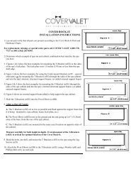
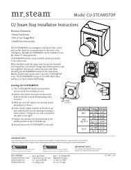
<strong>Installation</strong>, <strong>Operation</strong> & <strong>Maintenance</strong> <strong>Manual</strong>__________________________________________________________________________mr.steam®TYPICAL MR.STEAM INSTALLATIONNOTE: Drawings for illustrative purposes only.Consult with qualified designer, architect orcontractor for steam room construction details.Provide unions as required to facilitateinstallation and disconnect of piping!CAUTION The control features an integraltemperature sensor. Locate the control in a locationrepresentative of the desired steambathing temperatures.Do not locate the control above or near thesteam head or direct steam emissions.Control cable(located behindthe wall)iSteam ® , iTempo or iTempo/Plus ControlRefer to Control<strong>Installation</strong> <strong>Manual</strong>for installationinformationI N S T A L L E RField installedpower supplyField installedwater supply lineSteamGeneratorDrain Valve must be closedwhen the optionalAutoFlush is not installedWhen installing the optional AromaSteam, install adownward facing 90-degree T in the steam supplyline. See the AromaSteam <strong>Installation</strong> <strong>Manual</strong> forcomplete information.Field installedsteam supply pipe!Steam Head (shown with optional acrylic shield)See page 7 for Steam Head <strong>Installation</strong> informationCAUTIONTo avoid unintentional steambath operation, do not locate the controlwhere other controls, accessories, shower heads, valves, body sprays or similar within theshower could cause confusion or interfere with the Mr.Steam control’s intended use and function.TYPICAL INSTALLATION INSTRUCTIONSFOR MODELS <strong>MS</strong> SUPER 4E, 5E & 6E (shown with optional AutoFlush)1. Install each steam generator as in a single installation. Install generatorsas close as practical to each other, not exceeding 10 feet.The interconnecting cable length is 12 feet.5Printed Circuit Board Componentshown enlarged for illustrative purpose.iSteam oriTempo/PlusControl2. ! WARNING Shock Hazard. Power must be disconnectedat the main electrical supply. Remove steam gen-Primary Uniterator covers. Retain screws and covers for reuse.PowerSupplyInterconnecting3. Connect the iSteam ® or iTempo/Plus control toCable PN 103904either unit as per the <strong>Installation</strong> <strong>Manual</strong> suppliedwith each control.4. Remove one knock-out on each generator as shown.Water FeedInsert the ends of interconnecting cable providedLine(PN 103904) through the knock-outs as shown indiagram. Connect each end to the printed circuitboard connector labeled "TANDEM" as shown.5. Prevent the interconnecting cable from contactinghot surfaces such as steam outlet, safety valve andthe like.6. Connect separate plumbing and power suppliesfor each unit. Replace covers with cover screws.7. Provide unions as required to facilitate installationand disconnection of pipingSecondary UnitNOTE: The secondary unit will de-energize when thesteam room reaches steambathing temperature resultingin a more gentle and energy efficient operation.All drawings are for illustrative purposes onlyControlCableSteam Headsshown withoptional acrylicshieldsOptional AutoFlush ® , see AutoFlush<strong>Installation</strong> page 13