3 TON - 6 TON CPC/CPH SERIES - Goodman
3 TON - 6 TON CPC/CPH SERIES - Goodman
3 TON - 6 TON CPC/CPH SERIES - Goodman

Create successful ePaper yourself
Turn your PDF publications into a flip-book with our unique Google optimized e-Paper software.
INSTALLATION INSTRUCTIONS FORLIGHT COMMERCIAL SELF-CONTAINEDPACKAGED HEATING & COOLING UNIT3 <strong>TON</strong> - 6 <strong>TON</strong> <strong>CPC</strong>/<strong>CPH</strong> <strong>SERIES</strong>RECOGNIZE THIS SYMBOL AS A SAFETY PRECAUTION.ATTENTION INSTALLING PERSONNELPrior to installation, thoroughly familiarize yourself with this Installation Manual. Observe all safety warnings.During installation or repair, caution is to be observed.It is your responsibility to install the product safely and to educate the customer on its safe use.All information contained herein is subject to change without notice.These installation instructions cover the outdoorinstallation of single package electric heating andcooling units. See the Specification Sheet applicableto your model* for information regarding accessories.*NOTE:Please contact your distributor orour website for the applicableSpecification Sheet referred to inthis manual.<strong>Goodman</strong> Manufacturing Company, L.P.IO-399A 5151 Felipe, Suite 500, Houston, TX 770565/12 www.goodmanmfg.com www.amana-hac.com© 2010,2012 <strong>Goodman</strong> Manufacturing Company, L.P.
WARNINGTHIS UNIT MUST NOT BE USED AS A “CONSTRUCTION HEATER”DURING THE FINISHING PHASES OF CONSTRUCTION ON A NEWSTRUCTURE. THIS TYPE OF USE MAY RESULT IN PREMATURE FAILUREOF THE UNIT DUE TO EXTREMELY LOW RETURN AIR TEMPERATURESAND EXPOSURE TO CORROSIVE OR VERY DIRTY ATMOSPHERES.WARNINGHIGH VOLTAGE!DISCONNECT ALL POWER BEFORE SERVICING ORINSTALLING THIS UNIT. MULTIPLE POWER SOURCES MAYBE PRESENT. FAILURE TO DO SO MAY CAUSE PROPERTYDAMAGE, PERSONAL INJURY OR DEATH.WARNINGTO PREVENT THE RISK OF PROPERTY DAMAGE, PERSONAL INJURY, OR DEATH,DO NOT STORE COMBUSTIBLE MATERIALS OR USE GASOLINE OR OTHERFLAMMABLE LIQUIDS OR VAPORS IN THE VICINITY OF THIS APPLIANCE.GENERAL INFORMATIONWARNINGTO PREVENT PROPERTY DAMAGE PERSONAL INJURY OR DEATH, DUETO FIRE, EXPLOSIONS, SMOKE, SOOT, CONDENSATION, ELECTRICSHOCK OR CARBON MONOXIDE, THIS UNIT MUST BE PROPERLYINSTALLED, REPAIRED, OPERATED, AND MAINTAINED.This unit is approved for outdoor installation ONLY.Rated performance is achieved after 72 hours of operation.To assure that your unit operates safely and efficiently,it must be installed, operated, and maintained in accordancewith these installation and operating instructions,all local building codes and ordinances.EPA REGULATIONSIMPORTANT: THE UNITED STATES ENVIRONMENTAL PROTECTIONAGENCY (EPA) HAS ISSUED VARIOUS REGULATIONS REGARDINGTHE INTRODUCTION AND DISPOSAL OF REFRIGERANTS IN THISUNIT. FAILURE TO FOLLOW THESE REGULATIONS MAY HARM THEENVIRONMENT AND CAN LEAD TO THE IMPOSITION OFSUBSTANTIAL FINES. BECAUSE REGULATIONS MAY VARY DUE TOPASSAGE OF NEW LAWS, WE SUGGEST A CERTIFIED TECHNICIANPERFORM ANY WORK DONE ON THIS UNIT. SHOULD YOU HAVEANY QUESTIONS PLEASE CONTACT THE LOCAL OFFICE OF THEEPA.NATIONAL CODESThis product is designed and manufactured to permit installationin accordance with National Codes. It is the installer’sresponsibility to install the product in accordance with NationalCodes and/or prevailing local codes and regulations.The heating and cooling capacities of the unit should begreater than or equal to the design heating and cooling loadsof the area to be conditioned. The loads should be calculatedby an approved method or in accordance with ASHRAE Guideor Manual J - Load Calculations published by the Air ConditioningContractors of America.Obtain from:American National Standards Institute1430 BroadwayNew York, NY 10018System design and installation should also, where applicable,follow information presented in accepted industry guides suchas the ASHRAE Handbooks. The manufacturer assumes noresponsibility for equipment installed in violation of any codeor regulation. The mechanical installation of the packagedroof top units consists of making final connections betweenthe unit and building services; supply and return duct connections;and drain connections (if required). The internalsystems of the unit are completely factory-installed and testedprior to shipment.Units are generally installed on a steel roof mounting curbassembly which has been shipped to the job site for installationon the roof structure prior to the arrival of the unit. Themodel number shown on the unit’s identification plate identifiesthe various components of the unit such as refrigerationtonnage, heating input and voltage.Carefully inspect the unit for damage including damage tothe cabinetry. Any bolts or screws which may have loosenedin transit must be re-tightened. In the event of damage, thereceiver should:1. Make notation on delivery receipt of any visibledamage to shipment or container.2. Notify carrier promptly and request an inspection.3. In case of concealed damage, carrier should benotified as soon as possible-preferably within 5 days.4. File the claim with the following supporting documents:a. Original Bill of Lading, certified copy, or indemnitybond.b. Original paid freight bill or indemnity in lieu thereof.c. Original invoice or certified copy thereof, showingtrade and other discounts or reductions.d. Copy of the inspection report issued by carrierrepresentative at the time damage is reported to thecarrier. The carrier is responsible for making promptinspection of damage and for a thoroughinvestigation of each claim. The distributor ormanufacturer will not accept claims from dealers fortransportation damage.3
NOTE: When inspecting the unit for transportation damage,remove all packaging materials. Recycle or dispose of thepackaging material according to local codes.PRE-INSTALLATION CHECKSCarefully read all instructions for the installation prior to installingunit. Ensure each step or procedure is understoodand any special considerations are taken into account beforestarting installation. Assemble all tools, hardware andsupplies needed to complete the installation. Some items mayneed to be purchased locally.UNIT LOCATIONWARNINGTO PREVENT POSSIBLE EQUIPMENT DAMAGE, PROPERTY DAMAGE,PERSONAL INJURY OR DEATH, THE FOLLOWING BULLET POINTS MUSTBE OBSERVED WHEN INSTALLING THE UNIT.IMPORTANT NOTE: Remove wood shipping rails prior toinstallation of the unit.ALL INSTALLATIONS:IMPORTANT NOTE: If a crankcase heater is used, the unitshould be energized 24 hours prior to compressor start up toensure crankcase heater has sufficiently warmed the compressor.Compressor damage may occur if this step is not followed.NOTE: Appliance is shipped from factory for vertical ductapplication.Proper installation of the unit ensures trouble-free operation.Improper installation can result in problems ranging fromnoisy operation to property or equipment damages, dangerousconditions that could result in injury or personal propertydamage and could void the warranty. Give this booklet to theuser and explain it’s provisions. The user should retain theseinstructions for future reference.• For proper operation and condensate drainage, theunit must be mounted level.• Do not locate the unit in an area where the outdoorair will be frequently contaminated by compoundscontaining chlorine or fluorine. Common sources ofsuch compounds include swimming pool chemicalsand chlorine bleaches, paint stripper, adhesives,paints, varnishes, sealers, waxes (which are not yetdried) and solvents used during construction andremodeling. Various commercial and industrialprocesses may also be sources of chlorine/fluorinecompounds.• To avoid possible illness or death of the buildingoccupants, do NOT locate outside air intake device(economizer, manual fresh air intake, motorized freshair intake) too close to an exhaust outlet, gas venttermination, or plumbing vent outlet. For specificdistances required, consult local codes.• Allow minimum clearances from the enclosure for fireprotection, proper operation, and service access (seeUnit Clearances). These clearances must bepermanently maintained.• When the unit is heating, the temperature of the returnair entering the unit must be between 50°F and 100°F.GROUND LEVEL INSTALLATIONS ONLY:• When the unit is installed on the ground adjacent tothe building, a level concrete (or equal) base isrecommended. Prepare a base that is 3” larger thanthe package unit footprint and a minimum of 3” thick.• The base should also be located where no runoff ofwater from higher ground can collect in the unit.ROOF TOP INSTALLATIONS ONLY:• To avoid possible property damage or personal injury,the roof must have sufficient structural strength to carrythe weight of the unit(s) and snow or water loads asrequired by local codes. Consult a structural engineerto determine the weight capabilities of the roof.• The unit may be installed directly on wood floors oron Class A, Class B, or Class C roof covering material.• To avoid possible personal injury, a safe, flat surfacefor service personnel should be provided.• Adequate clearances from the unit to any adjacentpublic walkways, adjacent buildings, building openingsor openable windows must be maintained inaccordance with National Codes.UNIT PRECAUTIONS• Do not stand or walk on the unit.• Do not drill holes anywhere in panels or in the baseframe of the unit. Unit access panels providestructural support.• Do not remove any access panels until unit has beeninstalled on roof curb or field supplied structure.• Do not roll unit across finished roof without priorapproval of owner or architect.• Do not skid or slide on any surface as this maydamage unit base. The unit must be stored on aflat, level surface. Protect the condenser coilbecause it is easily damaged.ROOF CURB INSTALLATIONS ONLY:Curb installations must comply with local codes and shouldbe done in accordance with the established guidelines of theNational Roofing Contractors Association.Proper unit installation requires that the roof curb be firmlyand permanently attached to the roof structure. Check foradequate fastening method prior to setting the unit on thecurb.4
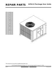
Full perimeter roof curbs are available from the factory andare shipped unassembled. Field assembly, squaring, levelingand mounting on the roof structure are the responsibilityof the installing contractor. All required hardware necessaryfor the assembly of the sheet metal curb is included in thecurb accessory.WARNINGTO PREVENT POSSIBLE EQUIPMENT DAMAGE, PROPERTY DAMAGE,PERSONAL INJURY OR DEATH, THE FOLLOWING BULLET POINTS MUSTBE OBSERVED WHEN INSTALLING THE UNIT.• Sufficient structural support must be determined priorto locating and mounting the curb and package unit.• Ductwork must be constructed using industryguidelines. The duct work must be placed into theroof curb before mounting the package unit. Our fullperimeter curbs include duct connection frames to beassembled with the curb. Cantilevered type curbsare not available from the factory.• Curb insulation, cant strips, flashing and generalroofing material are furnished by the contractor.The curbs must be supported on parallel sides by roof members.The roof members must not penetrate supply and returnduct opening areas as damage to the unit might occur.NOTE: The unit and curb accessories are designed to allowvertical duct installation before unit placement. Ductinstallation after unit placement is not recommended.Adequate clearance around the unit should be kept for safety,service, maintenance, and proper unit operation. A total clearanceof 75” on the main control panel side of the unit is recommendedto facilitate possible fan shaft, coil, and electricheat. A clearance of 48” is recommended on all other sidesof the unit to facilitate possible compressor removal, to allowservice access and to insure proper ventilation and condenserairflow. The unit must not be installed beneath any obstruction.The unit should be installed remote from all buildingexhausts to inhibit ingestion of exhaust air into the unit freshair intake.INSULATEDPANELSCAUTIONALL CURBS LOOK SIMILAR. TO AVOID INCORRECT CURBPOSITIONING, CHECK JOB PLANS CAREFULLY AND VERIFY MARKINGSON CURB ASSEMBLY. INSTRUCTIONS MAY VARY IN CURB STYLES ANDSUPERSEDES INFORMATION SHOWN.See the manual shipped with the roof curb for assembly andinstallation instructions.48”CLEARANCESROOF CURB INSTALLATIONROOF CURB POST-INSTALLATIONCHECKSAfter installation, check the top of the curb, duct connectionframe and duct flanges to make sure gasket has been appliedproperly. Gasket should be firmly applied to the top ofthe curb perimeter, duct flanges and any exposed duct connectionframe. If gasket is loose, reapply using strong weatherresistant adhesive.48”75”UNIT CLEARANCES5
PROTRUSIONInspect curb to ensure that none of the utility services (electric)routed through the curb protrude above the curb.CAUTIONIF PROTRUSIONS EXIST, DO NO ATTEMPT TO SET UNIT ON CURB.ROOF TOP DUCT CONNECTIONSInstall all duct connections on the unit before placing the uniton rooftop.HORIZONTAL DISCHARGEFor horizontal discharge, remove the supply and return ductcovers and place them over the vertical discharge return andsupply openings. Install with insulation facing up, using thelonger screws provided in the literature package.Ensure that the top of the duct connection frame is flush withthe top of the roof curb.Flexible duct connectors between the unit and ducts are recommended.Insulate and weatherproof all external ductworkand joints as required and in accordance with local codes.12”6 3/16”17” 7 3/8”SUPPLYREMOVECOVERS11” 4 7/8””RETURNHORIZONTAL DISCHARGE DUCT CONNECTIONS25”RIGGING DETAILSWARNINGTO PREVENT PROPERTY DAMAGE, THE UNIT SHOULD REMAIN IN AN UPRIGHTPOSITION DURING ALL RIGGING AND MOVING OPERATIONS. TO FACILITATELIFTING AND MOVING WHEN A CRANE IS USED, PLACE THE UNIT IN ANADEQUATE CABLE SLING.CAUTIONIF UNITS ARE LIFTED TWO AT A TIME, THE FORK HOLES ON THECONDENSER END OF THE UNIT MUST NOT BE USED. MINIMUM FORKLENGTH IS 42” TO PREVENT DAMAGE TO THE UNIT; HOWEVER, 48”IS RECOMMENDED.Provisions for forks have been included in the unit base frame.No other fork locations are approved.WARNINGTO PREVENT POSSIBLE EQUIPMENT DAMAGE, PROPERTY DAMAGE, PERSONALINJURY OR DEATH, THE FOLLOWING BULLET POINTS MUST BE OBSERVEDWHEN INSTALLING THE UNIT.• Unit must be lifted by the four lifting holes located atthe base frame corners.• Lifting cables should be attached to the unit withshackles.• The distance between the crane hook and the top ofthe unit must not be less than 60”.• Two spreader bars must span over the unit to preventdamage to the cabinet by the lift cables. Spreaderbars must be of sufficient length so that cables do notcome in contact with the unit during transport.Remove wood struts mounted beneath unit baseframe before setting unit on roof curb. These strutsare intended to protect unit base frame from fork liftdamage. Removal is accomplished by extracting thesheet metal retainers and pulling the struts throughthe base of the unit. Refer to rigging label on the unit.Important: If using bottom discharge with roof curb, ductworkshould be attached to the curb prior to installing theunit. Ductwork dimensions are shown in Roof Curb InstallationInstructions.Refer to the Roof Curb Installation Instructions for proper curbinstallation. Curbing must be installed in compliance with theNational Roofing Contractors Association Manual.6
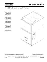
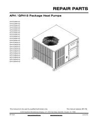
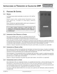
Lower unit carefully onto roof mounting curb. While rigging unit, center of gravity will cause condenser end to be lowerthan supply air end.To assist in determining rigging requirements, unit weights are shown as follows:ACYCONDENSERCOILRETURNEVAPORATOR COILCGSUPPLYBCOMPRESSORDXCORNER & CENTER OF GRAVITY LOCATIONSModelX(in)Y(in)Shipping Weight(lbs)Operating Weight(lbs)Corner Weights ( lbs )A B C D<strong>CPC</strong>036* 35 27 525 500 115 150 105 130<strong>CPC</strong>048* 35 27 560 535 125 160 110 140<strong>CPC</strong>060* 35 27 605 580 135 170 120 155<strong>CPC</strong>072* 35 27 665 640 150 190 130 170<strong>CPH</strong>036* 34 28 605 580 130 180 110 155<strong>CPH</strong>048* 34 28 610 585 135 185 115 155<strong>CPH</strong>060* 34 28 615 590 135 185 115 160<strong>CPH</strong>072* 34 28 675 650 145 205 125 175* Weights shown are belt drive with no accessories.7
CAUTIONTO PREVENT SEVERE DAMAGE TO THE BOTTOM OF THE UNIT, DO NOTFORK LIFT UNIT AFTER WOOD STRUTS HAVE BEEN REMOVED.Bring condenser end of unit into alignment with the curb. Withcondenser end of the unit resting on curb member and usingcurb as a fulcrum, lower opposite end of the unit until entireunit is seated on the curb. When a rectangular cantilevercurb is used, care should be taken to center the unit. Checkfor proper alignment and orientation of supply and return openingswith duct.RIGGING REMOVALCAUTIONTO PREVENT DAMAGE TO THE UNIT, DO NOT ALLOW CRANE HOOKSAND SPREADER BARS TO REST ON THE ROOF OF THE UNIT.Remove spreader bars, lifting cables and other rigging equipment.ELECTRICAL WIRINGWARNINGHIGH VOLTAGE!DISCONNECT ALL POWER BEFORE SERVICING ORINSTALLING THIS UNIT. MULTIPLE POWER SOURCES MAYBE PRESENT. FAILURE TO DO SO MAY CAUSE PROPERTYDAMAGE, PERSONAL INJURY OR DEATH.All line voltage connections must be made through weatherprooffittings. All exterior power supply and ground wiringmust be in approved weatherproof conduit.The main power supply wiring to the unit and low voltagewiring to accessory controls must be done in accordance withthese instructions, the latest edition of the National ElectricalCode (ANSI/NFPA 70), and all local codes and ordinances.All field wiring shall conform with the temperature limitationsfor Type T wire (63°F/35°C rise).The unit is factory wired for the voltage shown on the unit’sdata plate. Refer to model nomenclature in Appendix D forvoltage requirement for your unit.NOTE: If supply voltage is 208V, lead on primary of transformermust be moved from the 230V to the 208V tap. Referto wiring diagram on unit for details.Main power wiring should be sized for the minimum wireampacity shown on the unit’s data plate. Size wires in accordancewith the ampacity tables in Article 310 of the NationalElectrical Code. If long wires are required, it may be necessaryto increase the wire size to prevent excessive voltagedrop. Wires should be sized for a maximum of 3% voltagedrop.CAUTIONTO AVOID PROPERTY DAMAGE OR PERSONAL INJURY DUE TO FIRE, USEONLY COPPER CONDUCTORS.CAUTIONWARNINGHIGH VOLTAGE!TO AVOID PERSONAL INJURY OR DEATH DUE TOELECTRICAL SHOCK, DO NOT TAMPER WITH FACTORYWIRING. THE INTERNAL POWER AND CONTROL WIRINGOF THESE UNITS ARE FACTORY-INSTALLED AND HAVEBEEN THOROUGHLY TESTED PRIOR TO SHIPMENT.CONTACT YOUR LOCAL REPRESENTATIVE IFASSISTANCE IS REQUIRED.CAUTIONTO PREVENT DAMAGE TO THE WIRING, PROTECT WIRING FROMSHARP EDGES. FOLLOW NATIONAL ELECTRICAL CODE AND ALLLOCAL CODES AND ORDINANCES. DO NOT ROUTE WIRES THROUGHREMOVABLE ACCESS PANELS.CAUTIONCONDUIT AND FITTINGS MUST BE WEATHER-TIGHT TO PREVENTWATER ENTRY INTO THE BUILDING.For unit protection, use a fuse or HACR circuit breaker that isin excess of the circuit ampacity, but less than or equal to themaximum overcurrent protection device. DO NOT EXCEEDTHE MAXIMUM OVERCURRENT DEVICE SIZE SHOWNON UNIT DATA PLATE.8LABEL ALL WIRES PRIOR TO DISCONNECTION WHEN SERVICINGCONTROLS. WIRING ERRORS CAN CAUSE IMPROPER ANDDANGEROUS OPERATION. VERIFY PROPER OPERATION AFTERSERVICING.NOTE: A weather-tight disconnect switch, properly sized forthe unit total load, must be field installed. An external fieldsupplied disconnect may be mounted on the exterior panel.Ensure the data plate is not covered by the field-supplieddisconnect switch.• Some disconnect switches are not fused. Protect thepower leads at the point of distribution in accordancewith the unit’s data plate.• The unit must be electrically grounded in accordancewith local codes or, in the absence of local codes,with the latest edition of the National Electrical Code(ANSI-NFPA 70). A ground lug is provided for thispurpose. Size grounding conductor in accordancewith Table 250-95 of the National Electrical Code. Donot use the ground lug for connecting a neutralconductor.• Remove plug in panel located at the condenser endof unit and route conduit to control box. Remove plugin control box and connect power wiring to thecontactor closest to the entrance. If Single Point kit isused, refer to Installation Instructions supplied withkit.
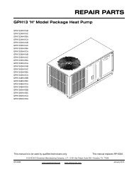
MAIN POWERLOW VOLTAGEBLOCKRETURN3.5 DIA.LOW VOLTAGEENTRANCEPOWER THRUTHE CURBCONTROL BOXSUPPLYPOWER THRUTHE CURB4 1/2”WARNINGFAILURE OF UNIT DUE TO OPERATION ON IMPROPER LINE VOLTAGEOR WITH EXCESSIVE PHASE UNBALANCE CONSTITUTES PRODUCTABUSE AND WILL VOID YOUR WARRANTY AND MAY CAUSE SEVEREDAMAGE TO THE UNIT ELECTRICAL COMPONENTS.Areas Without Convenience OutletIt is recommended that an independent 115V power sourcebe brought to the vicinity of the roof top unit for portable lightsand tools used by the service mechanic.UNITS INSTALLED ON ROOF TOPSMain power and low voltage wiring may enter the unit throughthe condenser end or through the roof curb. Install conduitconnectors at the desired entrance locations. External connectorsmust be weatherproof. All holes in the unit base mustbe sealed (including those around conduit nuts) to preventwater leakage into building. All required conduit and fittingsare to be field supplied.Supply voltage to roof top unit must not vary by more than10% of the value indicated on the unit’s data plate. Phasevoltage unbalance must not exceed 2%. Contact your localpower company for correction of improper voltage or phaseunbalance.HIGH VOLTAGE ENTRANCE(REMOVE PLUG)12 3/8”47 1/2”7 1/2”ELECTRICAL ENTRANCE AND THRU CURBLOW VOLTAGE CONTROL WIRING1. A 24V thermostat must be installed for unit operation.It may be purchased with the unit or field -supplied.Thermostats may be programmable orelectromechanical as required.2. Locate thermostat or remote sensor in the conditionedspace where it will sense average temperature. Donot locate the device where it may be directly exposedto supply air, sunlight or other sources of heat. Followinstallation instructions packaged with the thermostat.3. Use #18 AWG wire for 24V control wiring runs notexceeding 75 feet. Use #16 AWG wire for 24V controlwiring runs not exceeding 125 feet. Use #14 AWGwire for 24V control wiring runs not exceeding 200feet. Low voltage wiring may be National ElectricalCode (NEC) Class 2 where permitted by local codes.4. Route thermostat wires from sub-base terminals tothe unit. Control wiring should enter through thecondenser panel opening indicated in “ElectricalEntrance Locations” figure. Connect thermostat andany accessory wiring to low voltage terminal blockTB1 in the main control box.NOTE: Field-supplied conduit may need to be installeddepending on unit/curb configuration. Use #18 AWG solidconductor wire whenever connecting thermostat wires toterminals on sub-base. DO NOT use larger than #18 AWGwire. A transition to #18 AWG wire may be required beforeentering thermostat sub-base.* (6 Ton - 34 1/4”)1:430 1/4”*LOW VOLTAGE ENTRANCETERMINAL THERMOSTATRed R (24V)Green G (Fan)Orange O (Rev. Valve)White W1 (Heat, 2nd)*Brown W2 (Heat 3rd)*Yellow Y (Cool)C (Blue) C (Common)*Optional field installed heat connections<strong>CPC</strong>/H 036 THROUGH 0729
CIRCULATING AIR AND FILTERSSTARTUP, ADJUSTMENTS, AND CHECKSDUCTWORKThe supply duct from the unit through a wall may be installedwithout clearance. However, minimum unit clearances mustbe maintained (see “Clearances” section). The supply ductshould be provided with an access panel large enough toinspect the air chamber downstream of the heat exchanger.A cover should be tightly attached to prevent air leaks.Ductwork dimensions are shown in the roof curb installationmanual.If desired, supply and return duct connections to the unit maybe made with flexible connections to reduce possible unitoperating sound transmission.VENTINGNOTE: Venting is self-contained.CONDENSATE DRAIN CONNECTIONCONDENSATE DRAIN CONNECTIONA 3/4” NPT drain connection is supplied for condensate piping.An external trap must be installed for proper condensatedrainage.DRAINCONNECTIONHIGH VOLTAGE!TO AVOID PERSONAL INJURY OR DEATH DUE TOELECTRICAL SHOCK, BOND THE FRAME OF THIS UNIT TOTHE BUILDING ELECTRICAL GROUND BY USE OF THEGROUNDING TERMINAL PROVIDED OR OTHERACCEPTABLE MEANS. DISCONNECT ALL POWER BEFORESERVICING OR INSTALLING THIS UNIT.PRE-STARTUP INSTRUCTIONSWARNINGCAUTIONTO PREVENT PROPERTY DAMAGE OR PERSONAL INJURY, DO NOTSTART THE UNIT UNTIL ALL NECESSARY PRE-CHECKS AND TESTSHAVE BEEN PERFORMED.Prior to the beginning of Startup, Adjustments, and Checksprocedures, the following steps should be completed in thebuilding.THERMOSTAT. Set the thermostat in the conditionedspace at a point at least 10°F below zone temperature.Set the thermostat system switch on COOL and thefan switch on AUTO.NIGHT SETBACK THERMOSTAT (OPTIONAL). Setthermostat at a point at least 10°F below zonetemperature.UNIT2" MINIMUMWARNINGFLEXIBLETUBING-HOSEOR PIPEA POSITIVE LIQUIDSEAL IS REQUIRED3" MINIMUMDrain ConnectionInstall condensate drain trap as shown. Use 3/4" drain lineand fittings or larger. Do not operate without trap.HORIZONTAL DRAINDrainage of condensate directly onto the roof may be acceptable;refer to local code. It is recommended that a smalldrip pad of either stone, mortar, wood or metal be provided toprevent any possible damage to the roof.CLEANINGDue to the fact that drain pans in any air conditioning unitwill have some moisture in them, algae and fungus willgrow due to airborne bacteria and spores. Periodic cleaningis necessary to prevent this build-up from plugging thedrain.MOVING MACHINERY HAZARD!TO PREVENT POSSIBLE PERSONAL INJURY OR DEATH, DISCONNECTPOWER TO THE UNIT AND PADLOCK IN THE “OFF” POSITION BEFORESERVICNG FANS.HEATING STARTUPOn new installations, or if a major component has been replaced,the operation of the unit must be checked.Check unit operation as outlined in the following instructions.If any sparking, odors, or unusual sounds are encountered,shut off electrical power and recheck for wiring errors, or obstructionsin or near the blower motors. Duct covers mustbe removed before operating unit.The Startup, Adjustments, and Checks procedure provides astep-by-step sequence which, if followed, will assure theproper startup of the equipment in the minimum amount oftime. Air balancing of duct system is not considered part ofthis procedure. However, it is an important phase of any airconditioning system startup and should be performed uponcompletion of the Startup, Adjustments, and Checks procedure.The Startup, Adjustments, and Checks procedure atoutside ambients below 55°F should be limited to a readinesscheck of the refrigeration system with the required finalcheck and calibration left to be completed when the outsideambient rises above 55°F.10
TOOLS REQUIREDRefrigeration gauge and manifoldVoltmeterClamp-on ammeterOhmmeterTest lead(Minimum #16 AWG with insulated alligator clips)Air temperature measuring deviceGeneral refrigeration mechanics’ toolsTEMPORARY HEATING OR COOLINGIf the unit is to be used for temporary heating or cooling, a“Startup, Adjustments, and Checks” must first be performedin accordance with this manual. Failure to comply with thisrequirement will void the warranty. After the machines areused for temporary heating or cooling, inspect the coils, fans,and motors for unacceptable levels of construction dust anddirt and install new filters.CONTRACTOR RESPONSIBILITYThe installing contractor must be certain that:• All supply and return air ductwork is in place andcorresponds with installation instructions.• All thermostats are mounted and wired in accordancewith installation instructions.• All electric power, all gas, hot water or steam lineconnections, and the condensate drain installationhave been made to each unit on the job. These mainsupply lines must be functional and capable ofoperating all units simultaneously.ROOF CURB INSTALLATION CHECKInspect the roof curb for correct installation. The unit and curbassembly should be level. Inspect the flashing of the roofmounting curb to the roof, especially at the corners, for goodworkmanship. Also check for leaks around gaskets. Note anydeficiencies in a separate report and forward to the contractor.OBSTRUCTIONS, FAN CLEARANCE AND WIRINGRemove any extraneous construction and shipping materialsthat may be found during this procedure. Rotate all fansmanually to check for proper clearances and that they rotatefreely. Check for bolts and screws that may have jarred looseduring shipment to the jobsite. Retighten if necessary. Retightenall electrical connections.PRE-STARTUP PRECAUTIONSIt is important to your safety that the unit has been properlygrounded during installation. Check ground lug connectionin main control box for tightness prior to closing circuit breakeror disconnect switch. Verify that supply voltage on line sideof disconnect agrees with voltage on unit identification plateand is within the utilization voltage range as indicated in AppendixC Electrical Data.System Voltage - That nominal voltage value assigned to acircuit or system for the purpose of designating its voltageclass.Nameplate Voltage - That voltage assigned to a piece ofequipment for the purpose of designating its voltage classand for the purpose of defining the minimum and maximumvoltage at which the equipment will operate.Utilization Voltage - The voltage of the line terminals of theequipment at which the equipment must give fully satisfactoryperformance. Once it is established that supply voltagewill be maintained within the utilization range under all systemconditions, check and calculate if an unbalanced conditionexists between phases. Calculate percent voltage unbalanceas follows:Three Phase Models Only3) PERCENT VOLTAGEUNBALANCE= 100 X2) MAXIMUM VOLTAGE DEVIATIONSFROM AVERAGE VOLTAGE1) AVERAGE VOLTAGEHOW TO USE THE FORMULA:EXAMPLE: With voltage of 220, 216, and 2131) Average Voltage = 220+216+213=649 / 3 = 2162) Maximum Voltage Deviations from Average Voltage = 220 - 216 = 443) Percent Voltage Unbalance = 100 x =400= 1.8%216 216Percent voltage unbalance MUST NOT exceed 2%.FIELD DUCT CONNECTIONSVerify that all duct connections are tight and that there is noair bypass between supply and return.FILTER SECTION CHECKRemove filter section access panels and check that filtersare properly installed. Note airflow arrows on filter frames.BEARING CHECKBELT DRIVE MODELS ONLYPrior to energizing any fans, check and make sure that allsetscrews are tight so that bearings are properly secured toshafts.For heat pump units, the airflow must be adjusted so that theair temperature rise falls within the ranges given stated onData Plate (see Appendix A - Blower Performance).TENSION AND ALIGNMENT ADJUSTMENTCorrect belt tension is very important to the life of your belt.Too loose a belt will shorten its life; too tight, premature motorand bearing failure will occur. Check you belt drive foradequate “run-in” belt tension by measuring the force requiredto deflect the belt at the midpoint of the span length. Belttension force can be measured using a belt tension gauge,available through most belt drive manufacturers.11
Ensure the hold-down bolts on the compressor are secureand have not vibrated loose during shipment. Check that vibrationgrommets have been installed. Visually check all pipingand clamps. The entire refrigeration system has beenfactory charged and tested, making it unnecessary to fieldcharge. Factory charges are shown on the unit nameplate.Install service manifold hoses. Gauges should read saturationpressure corresponding to ambient temperature. Chargeshould be checked to obtain 12° to 15° of sub-cooling persystem (i.e. compressor circuits).START-UP PROCEDURE AND CHECKLISTBegin with power turned off at all disconnects.t = Span length, inchesC = Center distance, inchesD = Larger sheave diameter, inchesd = Smaller sheave diameter, inchesh = Deflection height, inchesDRIVE BELT TENSION ADJUSTMENTDEFLECTIONTYPE SHEAVEDIAMETERFORCE (lbs)(in)BELT DRIVE Used NewDEFLECTION(in)A, AX Standard 3.0 to 4.0 4.2 ± .5 5.5 ± .5 0.313RECOMMENDED POUNDS OF FORCE PER BELTNew V-belts will drop rapidly during the first few hours of use.Check tension frequently during the first 24 hours of operation.Tension should fall between the minimum and maximumforce. To determine the deflection distance from a normalposition, measure the distance from sheave to sheave usinga straightedge or a cord. This is your reference line. On multiplebelt drives, an adjacent undeflected belt can be used asa reference.1. Turn thermostat system switch to “Cool,” and fanswitch to “Auto” and turn temperature setting as highas it will go.2. Inspect all registers and set them to the normal openposition.3. Turn on the electrical supply at the disconnect.4. Turn the fan switch to the “ON” position. The blowershould operate after a 7 second delay.5. Turn the fan switch to “Auto” position. The blowershould stop after a 65 second delay.6. Slowly lower the cooling temperature until the unitstarts. The compressor, blower and fan should nowbe operating. Allow the unit to run 10 minutes, makesure cool air is being supplied by the unit.7. Turn the temperature setting to the highest position,stopping the unit. The indoor blower will continue torun for 65 seconds.8. Turn the thermostat system switch to “OFF” anddisconnect all power when servicing the unit.WARNINGEVAPORATOR FAN ROTATION CHECK (THREE PHASE MODELSONLY)Check that fan rotates counter-clockwise when viewed fromthe drive side of unit and in accordance with rotation arrowshown on blower housing. If it does not, reverse the two incomingpower cables. In this case, repeat bearing check.Do not attempt to change load side wiring. Internal wiringassures all motors and compressors will rotate in correct directiononce evaporator fan motor rotation check has beenmade.ELECTRICAL INPUT CHECKMake preliminary check of evaporator fan ampere draw andverify that motor nameplate amps are not exceeded. A finalcheck of amp draw should be made upon completion of airbalancing of the duct system (see Appendix B).REFRIGERATION SYSTEM CHECKS12HIGH VOLTAGE!DISCONNECT ALL POWER BEFORE SERVICING ORINSTALLING THIS UNIT. MULTIPLE POWER SOURCES MAYBE PRESENT. FAILURE TO DO SO MAY CAUSE PROPERTYDAMAGE, PERSONAL INJURY OR DEATH.HEAT PUMP START-UP PROCEDURE9. Check the cooling mode for the heat pump in the samemanner as above. The reversing valve is energizedwhen the thermostat is placed in the cooling position.A clicking sound should be noticeable from thereversing valve. By lowering the temperature settingto call for cooling, the contractor is energized. Thecompressor, blower and fan should then be running.After the cooling mode is checked out, turn thethermostat system switch to “OFF”.10. Turn the thermostat system switch to “HEAT” and fanswitch to “AUTO”.
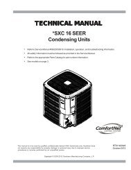
11. Slowly raise the heating temperature setting. Whenthe heating first stage makes contact, stop raising thetemperature setting.. The compressor, blower and fanshould now be running with the reversing valve in thede-energized (heating) position. After giving the unittime to settle out, make sure the unit is supplyingheated air.12. If the outdoor ambient is above 80°F, the unit may tripon its high pressure cut out when on heating. Thecompressor should stop. The heating cycle must bethoroughly checked, so postpone the test to anotherday when conditions are more suitable but-DO NOTFAIL TO TEST.If the outdoor ambient is low and the unit operatesproperly on the heating cycle, you may check thepressure cutout operation by blocking off the indoorreturn air until the unit trips.13. If unit operates properly in the heating cycle, raisethe temperature setting until the heating second stagemakes contact. Supplemental resistance heat, ifinstalled should now come on. Make sure it operatesproperly.NOTE: If outdoor thermostats are installed theoutdoor ambient must be below the set point of thesethermostats for the heaters to operate. It may benecessary to jumper these thermostats to checkheater operation if outdoor ambient is mild.14. For thermostats with emergency heat switch, returnto step 11. The emergency heat switch is located atthe bottom of the thermostat. Move the switch toemergency heat. The heat pump will stop, the blowerwill continue to run, all heaters will come on and thethermostat emergency heat light will come on.15. If checking the unit in the wintertime, when the outdoorcoil is cold enough to actuate the defrost control,observe at least one defrost cycle to make sure theunit defrosts completely.FINAL SYSTEM CHECKS16. Check to see if all supply and return air grilles areadjusted and the air distribution system is balancedfor the best compromise between heating and cooling.17. Check for air leaks in the ductwork. See Sections onAir Flow Adjustments.18. Make sure the unit is free of “rattles”, and the tubingin the unit is free from excessive vibration. Also makesure tubes or lines are not rubbing against each otheror sheet metal surfaces or edges. If so, correct thetrouble.19. Set the thermostat at the appropriate setting forcooling and heating or automatic changeover fornormal use.20. Be sure the Owner is instructed on the unit operation,filter, servicing, correct thermostat operation, etc.REFRIGERATION PERFORMANCE CHECKUnder normal summertime (full load) operating conditions,superheat should be between 8°F and 12°F and sub-coolingmeasured at the condenser outlet should be 15°F (nominal).A 25°F to 35°F temperature difference should exist betweenthe entering condenser air and the temperature correspondingto the compressor saturated discharge pressure. Checkthat compressor RLA corresponds to values shown in AppendixC. RLA draw can be much lower than values listed atlow load conditions and low ambient condensing temperatures.Values in Appendix C can slightly exceed at high loadconditions and high ambient condensing temperatures.COOLING CYCLEHEAT PUMP OPERATIONWhen the heat pump is in the cooling cycle, it operates exactlyas a Summer Air Conditioner unit. In this mode, all thecharts and data for service that apply to summer air conditioningapply to the heat pump. Most apply on the heatingcycle except that “condenser” becomes “evaporator”, “evaporator”becomes “condenser”, “cooling” becomes “heating”.HEATING CYCLEThe heat pump operates in the heating cycle by redirectingrefrigerant flow through the refrigerant circuit external to thecompressor. This is accomplished with through the reversingvalve. Hot discharge vapor from the compressor is directedto the indoor coil (evaporator on the cooling cycle) where theheat is removed, and the vapor condenses to liquid. It thengoes through the expansion device to the outdoor coil (condenseron the cooling cycle) where the liquid is evaporated,and the vapor goes to the compressor.When the solenoid valve coil is operated either from heatingto cooling or vice versa, the piston in the reversing valve tothe low pressure (high pressure) reverse positions in the reversingvalve.The following figures show a schematic of a heat pump onthe cooling cycle and the heating cycle. In addition to a reversingvalve, a heat pump is equipped with an expansiondevice and check valve for the indoor coil, and similar equipmentfor the outdoor coil. It is also provided with a defrostcontrol system.The expansion devices are flowrator distributors and performthe same function on the heating cycle as on the cooling cycle.The flowrator distributors also act as check valves to allowfor the reverse of refrigerant flow.13
COOLINGEVAPORATORINDOORCOILSERVICE VALVESERVICE PORTCOMPRESSORDISTRIBUTOREXPANSION DEVICECHECK VALVEORIFICE SERVICEVALVESERVICE PORTACCUMULATORSERVICE PORTCHECK VALVEORIFICEREVERSING VALVECONDENSEROUTDOORCOILDEFROST CONTROLDuring operation the power to the circuit board is controlledby a temperature sensor, which is clamped to a feeder tubeentering the outdoor coil. Defrost timing periods of 30,60 and90 minutes may be selected by setting the circuit board jumperto 30, 60 and 90 respectively. Accumulation of time for thetiming period selected starts when the sensor closes (approximately31° F), and when the wall thermostat calls forheat. At the end of the timing period, the unit’s defrost cyclewill be initiated provided the sensor remains closed. Whenthe sensor opens (approximately 75° F), the defrost cycle isterminated and the timing period is reset. If the defrost cycleis not terminated due to the sensor temperature, a twelveminute override interrupts the unit’s defrost period.HEATINGCONDENSERINDOORCOILSERVICE VALVECOMPRESSORDISTRIBUTORCHECK VALVEORIFICE SERVICEVALVESERVICE PORTACCUMULATORSERVICE PORTCHECK VALVEORIFICEREVERSING VALVEDISTRIBUTOREVAPORATOROUTDOORCOILWhen the heat pump is on the heating cycle, the outdoor coilis functioning as an evaporator. The temperature of the refrigerantin the outdoor coil must be below the temperature ofthe outdoor air in order to extract heat from the air. Thus, thegreater the difference in the outdoor temperature and theoutdoor coil temperature, the greater the heating capacity ofthe heat pump. This phenomenon is a characteristic of aheat pump. It is a good practice to provide supplementaryheat for all heat pump installations in areas where the temperaturedrops below 45° F. It is also a good practice toprovide sufficient supplementary heat to handle the entireheating requirement should there be a component failure ofthe heat pump, such as a compressor, or refrigerant leak,etc.Since the temperature of the refrigerant in the outdoor coil onthe heating cycle is generally below freezing point, frost formson the surfaces of the outdoor coil under certain weather conditionsof temperature and relative humidity. Therefore, it isnecessary to reverse the flow of the refrigerant to provide hotgas in the outdoor coil to melt the frost accumulation. This isaccomplished by reversing the heat pump to the cooling cycle.At the same time, the outdoor fan stops to hasten the temperaturerise of the outdoor coil and lessen the time requiredfor defrosting. The indoor blower continues to run and thesupplementary heaters are energized.AIR FLOW ADJUSTMENTSThe drive on the supply fan is typically set in the middle of theRPM range. The drive motor sheave pitch diameter is fieldadjustable for the required airflow. Refer to “DriveAdjustments” section below.When the final adjustments are complete, the current drawof the motor should be checked and compared to the fullload current rating of the motor. The amperage must not exceedthe service factor stamped on the motor nameplate.The total airflow must not be less than that required for operationof the electric heaters or the furnace.If an economizer is installed, check the unit operating balancewith the economizer at full outside air and at minimumoutside air. Upon completion of the air flow balancing, werecommend replacing the variable pitched motor sheave witha properly-sized fixed sheave. A matching fixed sheave willprovide longer belt and bearing life and vibration free operation.Initially, it is best to have a variable pitched motor sheavefor the purpose of airflow balancing, but once the balancehas been achieved, fixed sheaves maintain alignment andminimize vibration more effectively. For direct drive units, movegreen wire for fan.NOTE: Never run CFM below 350 CFM per ton, evaporatorfreezing or poor unit performance is possible.PSC MOTORAdjust the CFM for the unit by changing the speed tap of theindoor blower motor at the EBTDR “com” connection with theone of the speed taps on “M1” or “M2” (Black-High Speed,Blue-Medium Speed, Red-Low Speed).X-13 MOTORAdjust the CFM for the unit by changing the position of thelow voltage leads on the motor terminal block. Green is forFan Only. Yellow is for Cooling and Heat Pump Heating. Referto Appendix A for blower performance at each speed tap.NOTE: If more than one lead is energized simultaneously,the motor will run at the higher speed.14
DRIVE ADJUSTMENTSMOTOR SHEAVE ADJUSTMENTSVL, VM, & 2VP VARIABLE PITCH KEY TYPE MOTOR SHEAVESThe driving and driven motor sheaves should be in alignmentwith each other and the shafts parallel.VL & VM SHEAVES ADJUSTMENT1. Loosen set screw “B” using a 5/32" Allen key.2. Making half or full turns from closed position, adjustsheave pitch diameter for desired speed. DO NOTOPEN MORE THAN FIVE FULL TURNS.3. Tighten set screw “B” securely over flat.4. Carefully put on belts and adjust belt tension. DO NOTFORCE BELTS OVER GROOVES.5. Ensure all keys are in place and the set screws tightbefore starting drive. Recheck set screws and belttension after 24 hours service.NOTE: Future adjustments should be made by loosening thebelt tension and increasing or decreasing the pitch diameterof the sheave by half or full turns as required. Readjust belttension before starting drive.VL & VMSHEAVE DIAGRAMNOTE: Do not operate sheave with flange projecting beyondthe hub end.BMAINTENANCEWARNINGHIGH VOLTAGE!DISCONNECT ALL POWER BEFORE SERVICING ORINSTALLING THIS UNIT. MULTIPLE POWER SOURCES MAYBE PRESENT. FAILURE TO DO SO MAY CAUSE PROPERTYDAMAGE, PERSONAL INJURY OR DEATH.WARNINGTO PREVENT PERSONAL INJURY OR DEATH DUE TO IMPROPERINSTALLATION, ADJUSTMENT, ALTERATION, SERVICE ORMAINTENANCE, REFER TO THIS MANUAL. FOR ADDITIONALASSISTANCE OR INFORMATION, CONSULT A QUALIFIED INSTALLER,SERVICE AGENCY OR THE GAS SUPPLIER.CCAUTIONSHEET METAL PARTS, SCREWS, CLIPS AND SIMILAR ITEMS INHERENTLYHAVE SHARP EDGES, AND IT IS NECESSARY THAT THE INSTALLER ANDSERVICE PERSONNEL EXERCISE CAUTION.The Self Contained Packaged Air Conditioner and Heat Pumpshould operate for many years without excessive service callsif the unit is installed properly. However it is recommendedthat the homeowner inspect the unit before a seasonal startup. The coils should be free of debris so adequate airflow isachieved. The return and supply registers should be free ofany obstructions. The filters should be cleaned or replaced.These few steps will help to keep the product up time to amaximum. The Service section that follows should help inidentifying problems if the unit does not operate properly.FILTERSCAUTIONTO PREVENT PROPERTY DAMAGE DUE TO FIRE AND LOSS OFEQUIPMENT EFFICIENCY OR EQUIPMENT DAMAGE DUE TO DUST AND LINTBUILD UP ON INTERNAL PARTS, NEVER OPERATE UNIT WITHOUT AN AIRFILTER INSTALLED IN THE RETURN AIR SYSTEM.Every application may require a different frequency of replacementof dirty filters. Filters must be replaced at least everythree (3) months during operating seasons.Dirty filters are the most common cause of inadequate heatingor cooling performance. Filter inspection should be madeat least every two months; more often if necessary becauseof local conditions and usage.Dirty throwaway filters should be discarded and replaced witha new, clean filter.Disposable return air filters are supplied with this unit. Seethe unit Specification Sheet or Technical Manual for the correctsize and part number. To remove the filters, remove thefilter access panel on return side of the unit.CABINET FINISH MAINTENANCEUse a fine grade automotive wax on the cabinet finish tomaintain the finish’s original high luster. This is especiallyimportant in installations with extended periods of direct sunlight.CLEAN OUTSIDE COIL (QUALIFIED SERVICER ONLY)The coil with the outside air flowing over it should be inspectedannually and cleaned as frequently as necessary to keep thefinned areas free of lint, hair and debris.CONDENSER, EVAPORATOR, AND INDUCED DRAFT MOTORSBearings on the air circulating blower motor, condenser motorand the combustion fan motor are permanently lubricated.No additional oiling is required.15
LUBRICATIONThe fan shaft bearings, the 1 to 2 HP supply fan motors thecondenser fan motors and compressors are permanently lubricated.UNDERCHARGEAn undercharged heat pump on the heating cycle will causelow discharge pressure resulting in low suction pressure andfrost accumulation on the outdoor coil.FUNCTIONAL PARTSRefer to the unit Parts Catalog for a list of functional parts.Parts are available from your distributor.SERVICETHE FOLLOWING INFORMATION IS FOR USE BY QUALI-FIED SERVICE AGENCY ONLY: OTHERS SHOULD NOTATTEMPT TO SERVICE THIS EQUIPMENT.Common Causes of Unsatisfactory Operation of Heat Pumpon the Heating Cycle.INADEQUATE AIR VOLUME THROUGH INDOOR COILWhen a heat pump is in the heating cycle, the indoor coil isfunctioning as a condenser. The return air filter must alwaysbe clean, and sufficient air volume must pass through theindoor coil to prevent excessive discharge pressure, and highpressure cut out.OUTSIDE AIR INTO RETURN DUCTDo not introduce cold outside air into the return duct of a heatpump installation. Do not allow air entering the indoor coil todrop below 65° F. Air below this temperature will cause lowdischarge pressure, thus low suction pressure, and excessivedefrost cycling resulting in low heating output. It mayalso cause false defrosting.POOR “TERMINATING” SENSOR CONTACTThe unit’s defrost terminating sensor must make good thermalcontact with the outdoor coil tubing. Poor contact maynot terminate the unit’s defrost cycle quickly enough to preventthe unit from cutting out on high discharge pressure.MALFUNCTIONING REVERSING VALVE - THIS MAY BE DUE TO:1. Solenoid not energized - In order to determine if thesolenoid is energized, touch the nut that holds thesolenoid cover in place with a screwdriver. If the nutmagnetically holds the screwdriver, the solenoid isenergized and the unit is in the cooling cycle.2. No voltage at unit’s solenoid - Check unit voltage.If no voltage, check wiring circuit.3. Valve will not shift:a. Undercharged - check for leaks;b. Valve Body Damaged - Replace valve;c. Unit Properly Charged - If it is on the heating cycle,raise the discharge pressure by restricting airflowthrough the indoor coil. If the valve does not shift,tap it lightly on both ends with a screwdriver handle.DO NOT TAP THE VALVE BODY. If the unit is onthe cooling cycle, raise the discharge pressure byrestricting airflow through the outdoor coil. If the valvedoes not shift after the above attempts, cut the unitoff and wait until the discharge and suction pressureequalize, and repeat above steps. If the valve doesnot shift, replace it.16
APPENDIX A BLOWER PERFORMANCE TABLESDIRECT DRIVESTANDARD DOWN SHOT AND HORIZONTAL<strong>CPC</strong>/H036 DIRECT DRIVE DOWN SHOTSPEED TAPLOWMEDHIGHEXTERNAL STATICPRESSURE (ESP)in w.c.STANDARDCFMAMPS WATTS RPM0.10 1287 1.66 350 7700.20 1233 1.63 342 8150.30 1176 1.59 332 8580.40 1107 1.55 320 8910.50 1044 1.51 312 9240.60 965 1.45 296 9570.10 1476 2.08 446 8660.20 1421 2.03 432 8850.30 1334 1.96 414 9180.40 1255 1.90 396 9450.50 1180 1.84 386 9710.60 1085 1.78 368 9900.70 964 1.70 344 10230.30 1455 2.31 490 9620.40 1367 2.25 476 9840.50 1277 2.16 454 10060.60 1180 2.09 438 10250.70 1080 2.02 418 10390.80 922 1.90 386 1067SPEED TAPNOTES:LOWMEDHIGH<strong>CPC</strong>/H036 DIRECT DRIVE HORIZONTALEXTERNAL STATICPRESSURE (ESP)in w.c.STANDARDCFM17AMPS WATTS RPM0.10 1296 1.67 356 7640.20 1245 1.60 334 8300.30 1174 1.56 325 8610.40 1103 1.52 316 8910.50 1013 1.46 300 9350.10 1502 2.10 456 8360.20 1449 2.06 444 8640.30 1396 2.02 432 8910.40 1335 1.97 418 9160.50 1273 1.91 404 9400.60 1153 1.83 380 9730.70 996 1.71 346 10170.20 1516 2.36 506 9400.30 1454 2.31 496 9600.40 1392 2.26 486 9790.50 1273 2.17 458 10060.60 1183 2.09 441 10230.70 1092 2.02 424 10390.80 920 1.90 390 1067Tables represent dry coil without filter, to compensate for filter add 0.08" to measured E.S.P. SCFMcorrection for wet coil = 4 %.3 Ton models are shipped from the factory with speed tap set on LOW.
APPENDIX A BLOWER PERFORMANCE TABLESDIRECT DRIVESTANDARD DOWN SHOT AND HORIZONTALSPEED TAPLOWMEDHIGH<strong>CPC</strong>/H048 DIRECT DRIVE DOWN SHOTEXTERNAL STATICPRESSURE (ESP)in w.c.STANDARDCFMAMPS WATTS RPM0.10 1602 2.48 528 8350.20 1538 2.37 506 8780.30 1474 2.26 484 9210.40 1390 2.15 460 9500.50 1306 2.04 436 9790.10 1805 2.84 620 9350.20 1704 2.71 590 9670.30 1625 2.59 558 9900.40 1549 2.47 540 10120.50 1437 2.38 516 10300.60 1301 2.23 480 10500.70 1158 2.09 444 10720.10 1971 3.22 706 9680.20 1828 3.03 664 9980.30 1744 2.94 632 10170.40 1628 2.80 606 10340.50 1510 2.69 582 10500.60 1402 2.57 552 1067SPEED TAP<strong>CPC</strong>/H048 DIRECT DRIVE HORIZONTALEXTERNAL STATICPRESSURE (ESP)in w.c.STANDARDCFMAMPS WATTS RPM0.10 1622 2.54 539 8090.20 1558 2.43 517 852LOW0.30 1494 2.32 495 8950.40 1410 2.21 471 9240.50 1326 2.10 447 9530.10 1861 3.11 670 8860.20 1733 2.78 606 9180.30 1639 2.64 568 960MED0.40 1564 2.51 542 9840.50 1434 2.35 508 10170.60 1320 2.25 482 10390.70 1156 2.08 446 10670.10 1984 3.34 734 9490.20 1883 3.18 694 977HIGH0.30 1770 3.03 654 10010.40 1656 2.87 620 10270.50 1540 2.76 590 10440.60 1415 2.62 558 1061NOTES:Tables represent dry coil without filter, to co mp ensate for filter add 0.08" to measured E.S.P. SCFMcorrection for wet coil = 4 %.4 Ton models are shipped from the factory with speed tap set on MED.18
APPENDIX A BLOWER PERFORMANCE TABLESDIRECT DRIVESTANDARD <strong>CPC</strong>/H060 DOWN SHOTSPEEDTAPT1T2T3T4T5EXTERNAL STATICPRESSURE (ESP)in w.c.<strong>CPC</strong>/H060 DIRECT DRIVE DOWN SHOTSTANDARDCFM19AMPS WATTS RPM0.10 1334 1.65 180 6270.20 1286 1.75 192 6650.30 1212 1.83 202 7150.40 1144 1.94 216 7590.50 1077 1.99 222 7920.60 1039 2.10 238 8300.70 953 2.17 248 8740.80 904 2.27 258 9130.90 825 2.30 266 9400.10 1512 2.12 240 6820.20 1469 2.24 254 7200.30 1397 2.31 264 7590.40 1333 2.44 282 8030.50 1285 2.54 296 8360.60 1221 2.59 304 8740.70 1173 2.72 322 9130.80 1118 2.77 328 9460.90 1049 2.90 344 9840.10 2053 4.27 540 8690.20 2014 4.39 558 8960.30 1999 4.60 576 9290.40 1947 4.68 588 9570.50 1897 4.79 608 9890.60 1857 4.87 620 10120.70 1763 4.99 640 10500.80 1741 5.06 650 10720.90 1669 5.19 668 11050.10 2137 4.95 634 9130.20 2093 5.07 652 9400.30 2095 5.19 670 9620.40 2026 5.28 682 9900.50 1980 5.40 698 10180.60 1961 5.49 720 10390.70 1914 5.58 732 10720.80 1845 5.70 742 11000.90 1766 5.69 740 11270.10 2299 5.70 742 9420.20 2233 5.80 748 9690.30 2217 5.90 768 9900.40 2157 6.07 786 10180.50 2131 6.12 804 10450.60 2060 6.21 816 10730.70 2015 6.30 820 10950.80 1940 6.27 816 11110.90 1862 6.13 790 1128NOTES:Tables represent dry coil without filter, to compensate for filter add 0.08" to measured E.S.P. SCFMcorrection for wet coil = 4 %. 5 T on models are shipped from the factory with speed tap set on T4.
APPENDIX A BLOWER PERFORMANCE TABLESDIRECT DRIVESTANDARD <strong>CPC</strong>/H060 HORIZONTALSPEEDTAPT1T2T3T4T5EXTERNAL STATICPRESSURE (ESP)in w.c.<strong>CPC</strong>/H060 DIRECT DRIVE HORIZONTALSTANDARDCFM20AMPS WATTS RPM0.10 1355 1.57 174 5990.20 1281 1.66 182 6510.30 1235 1.76 196 6930.40 1168 1.81 202 7260.50 1118 1.94 218 7750.60 1049 2.03 232 8190.70 982 2.10 240 8580.80 922 2.14 246 8850.90 871 2.25 260 9270.10 1544 2.04 234 6600.20 1490 2.17 250 7040.30 1427 2.25 260 7420.40 1370 2.35 276 7810.50 1319 2.42 282 8090.60 1274 2.52 296 8490.70 1210 2.62 316 8910.80 1137 2.73 326 9350.90 1106 2.77 336 9570.10 2099 4.13 516 8250.20 2068 4.25 536 8520.30 2029 4.37 552 8850.40 1971 4.48 568 9130.50 1911 4.61 586 9500.60 1876 4.73 604 9730.70 1821 4.86 622 10120.80 1792 4.91 630 10280.90 1740 5.03 648 10670.10 2233 4.76 608 8630.20 2168 4.91 628 8960.30 2125 5.02 640 9240.40 2070 5.14 660 9510.50 2050 5.27 678 9790.60 1980 5.41 696 10120.70 1954 5.47 704 10340.80 1893 5.60 724 10670.90 1852 5.70 736 10890.10 2322 5.44 710 9040.20 2294 5.55 726 9340.30 2254 5.68 742 9580.40 2201 5.80 766 9900.50 2147 5.93 782 10170.60 2117 6.01 788 10390.70 2081 6.12 808 10600.80 2017 6.22 822 10940.90 1932 6.10 804 1111NOTES:Tables represent dry coil without filter, to compensate for filter add 0.08" to measured E.S.P. SCFMcorrection for wet coil = 4 %.
APPENDIX A BLOWER PERFORMANCE TABLESBELT DRIVESTANDARD DOWN SHOT<strong>CPC</strong>/H036 STANDARD BELT DRIVE DOWN SHOTTURNS OPENESP, InH 2 O0 1 2 3 4 5CFM BHP CFM BHP CFM BHP CFM BHP CFM BHP CFM BHP0.2 1424 0.30 1239 0.230.4 1520 0.39 1292 0.29 1073 0.22 779 0.140.6 1439 0.40 1192 0.30 944 0.21 619 0.120.8 1350 0.42 1101 0.31 864 0.221.0 1028 0.31 729 0.211.2 675 0.20<strong>CPC</strong>/H048 STANDARD BELT DRIVE DOWN SHOTTURNS OPENESP, In0 1 2 3 4 5H 2 OCFM BHP CFM BHP CFM BHP CFM BHP CFM BHP CFM BHP0.2 2129 0.64 1795 0.47 1550 0.350.4 1994 0.65 1701 0.49 1433 0.36 1163 0.220.6 1905 0.67 1606 0.50 1326 0.36 1025 0.220.8 1808 0.69 1565 0.54 1216 0.361.0 1473 0.55 1137 0.321.2 1103 0.41<strong>CPC</strong>/H060 STANDARD BELT DRIVE DOWN SHOTTURNS OPENESP, In0 1 2 3H 2 O4 5CFM BHP CFM BHP CFM BHP CFM BHP CFM BHP CFM BHP0.2 2579 1.01 2368 0.85 2175 0.691 1961 0.550.4 2513 1.05 2318 0.89 2089 0.73 1906 0.59 1666 0.440.6 2514 1.14 2276 0.94 2045 0.77 1797 0.60 1604 0.470.8 2261 1.01 2017 0.82 1760 0.631.0 1989 0.87 1730 0.681.2 1695 0.72<strong>CPC</strong>/H072 STANDARD BELT DRIVE DOWN SHOTTURNS OPENESP, In0 1 2 3H 2 O4 5CFM BHP CFM BHP CFM BHP CFM BHP CFM BHP CFM BHP0.2 2771 1.27 2567 1.05 2421 0.88 2220 0.710.4 2753 1.38 2573 1.15 2382 0.95 2186 0.77 1980 0.610.6 2655 1.42 2548 1.24 2360 1.02 2119 0.81 1934 0.650.8 2470 1.30 2331 1.11 2111 0.89 1868 0.691.0 2296 1.18 2078 0.96 1840 0.751.2 2040 1.02NOTES:Tables represent dry coil without filter, to compensate for filter add 0.08" to measured E.S.P.SCFM correction for wet coil = 4 %.21
APPENDIX A BLOWER PERFORMANCE TABLESBELT DRIVEHIGH STATIC DOWN SHOT<strong>CPC</strong>/H036 HIGH STATIC BELT DRIVE DOWN SHOTTURNS OPENESP, In0 1 2 3 4 5H 2 OCFM BHP CFM BHP CFM BHP CFM BHP CFM BHP CFM BHP0.6 1692 0.54 1449 0.41 1173 0.290.8 1678 0.58 1397 0.44 1107 0.31 854 0.211.0 1681 0.65 1381 0.49 1078 0.34 794 0.221.2 1681 0.71 1362 0.54 1062 0.391.4 1362 0.60 1066 0.441.6 1066 0.50 789 0.341.8 789 0.40<strong>CPC</strong>/H048 HIGH STATIC BELT DRIVE DOWN SHOTTURNS OPENESP, In0 1 2 3H 2 O4 5CFM BHP CFM BHP CFM BHP CFM BHP CFM BHP CFM BHP0.6 2194 0.85 1886 0.66 1580 0.490.8 2113 0.86 1832 0.70 1526 0.52 1219 0.371.0 2182 0.98 1776 0.73 1472 0.55 1166 0.391.2 2053 1.00 1780 0.80 1440 0.59 1111 0.401.4 1759 0.86 1421 0.64 1104 0.461.6 1442 0.72 1095 0.501.8 1095 0.56<strong>CPC</strong>/H060 HIGH STATIC BELT DRIVE DOWN SHOTTURNS OPENESP, InH 2 O0 1 2 3 4 5CFM BHP CFM BHP CFM BHP CFM BHP CFM BHP CFM BHP0.6 2331 1.01 2072 0.800.8 2324 1.10 2059 0.87 1791 0.661.0 2350 1.21 2058 0.95 1774 0.721.2 2367 1.33 2086 1.06 1776 0.791.4 2404 1.45 2111 1.17 1805 0.891.6 2136 1.28 1835 0.991.8 1868 1.10<strong>CPC</strong>/H072 HIGH STATIC BELT DRIVE DOWN SHOTTURNS OPENESP, In0 1 2 3H 2 O4 5CFM BHP CFM BHP CFM BHP CFM BHP CFM BHP CFM BHP0.6 2793 1.64 2603 1.39 2450 1.182 2270 0.970.8 2903 1.87 2696 1.57 2369 1.23 2236 1.05 1987 0.821.0 2776 1.86 2683 1.69 2445 1.38 2196 1.12 1968 0.901.2 2599 1.71 2539 1.57 2310 1.29 1932 0.961.4 2424 1.57 2305 1.40 2032 1.111.6 2172 1.38 2017 1.191.8 1953 1.22NOTES:Tables represent dry coil without filter, to compensate for filter add 0.08" to measured E.S.P.SCFM correction for wet coil = 4 %.22
APPENDIX A BLOWER PERFORMANCE TABLESBELT DRIVESTANDARD HORIZONTAL<strong>CPC</strong>/H036 STANDARD BELT DRIVE HORIZONTALTURNS OPENESP, InH 2 O0 1 2 3 4 5CFM BHP CFM BHP CFM BHP CFM BHP CFM BHP CFM BHP0.2 1658 0.35 1489 0.280.4 1560 0.36 1339 0.28 1129 0.210.6 1682 0.47 1436 0.36 1196 0.27 949 0.190.8 1581 0.50 1354 0.38 1096 0.28 828 0.181.0 1266 0.39 994 0.28 756 0.191.2 923 0.28<strong>CPC</strong>/H048 STANDARD BELT DRIVE HORIZONTALTURNS OPENESP, InH 2 O0 1 2 3 4 5CFM BHP CFM BHP CFM BHP CFM BHP CFM BHP CFM BHP0.2 1943 0.52 1714 0.400.4 2187 0.72 1876 0.55 1566 0.40 1270 0.260.6 2044 0.72 1761 0.56 1444 0.40 1136 0.260.8 1947 0.74 1704 0.59 1335 0.401.0 1598 0.60 1275 0.361.1 1208 0.45<strong>CPC</strong>/H060 STANDARD BELT DRIVE HORIZONTALTURNS OPENESP, In0 1 2 3H 2 O4 5CFM BHP CFM BHP CFM BHP CFM BHP CFM BHP CFM BHP0.2 2420 0.79 2198 0.640.4 2605 1.02 2358 0.84 2133 0.67 1874 0.520.6 2526 1.06 2300 0.88 2026 0.70 1806 0.550.8 2529 1.15 2252 0.93 1975 0.73 1670 0.541.0 2233 0.99 1943 0.78 1628 0.571.2 1907 0.83 1582 0.61<strong>CPC</strong>/H072 STANDARD BELT DRIVE HORIZONTALTURNS OPENESP, In0 1 2 3H 2 O4 5CFM BHP CFM BHP CFM BHP CFM BHP CFM BHP CFM BHP0.2 2784 1.30 2582 0.83 2411 0.790.4 2814 1.34 2620 1.19 2342 0.72 2105 0.660.6 2665 1.34 2583 1.19 2398 1.06 2103 0.62 1902 0.570.8 2689 1.38 2492 1.22 2370 1.07 2142 0.91 1816 0.511.0 2438 1.22 2275 1.09 2098 0.92 1883 0.781.2 2250 1.10 1996 0.92NOTES:Tables represent dry coil without filter, to compensate for filter add 0.08" to measured E.S.P.SCFM correction for wet coil = 4 %.23
APPENDIX A BLOWER PERFORMANCE TABLESBELT DRIVEHIGH STATIC HORIZONTAL<strong>CPC</strong>/H036 HIGH STATIC BELT DRIVE HORIZONTALTURNS OPENESP, InH 2 O0 1 2 3 4 5CFM BHP CFM BHP CFM BHP CFM BHP CFM BHP CFM BHP0.6 1742 0.50 1431 0.360.8 1626 0.52 1357 0.39 1078 0.271 1611 0.56 1315 0.42 1011 0.281.2 1605 0.62 1299 0.46 976 0.311.4 1605 0.68 1281 0.51 959 0.351.6 1281 0.57 981 0.411.8 981 0.47<strong>CPC</strong>/H048 HIGH STATIC BELT DRIVE HORIZONTALTURNS OPENESP, In0 1 2 3H 2 O4 5CFM BHP CFM BHP CFM BHP CFM BHP CFM BHP CFM BHP0.6 2056 0.72 1721 0.540.8 1996 0.77 1662 0.57 1328 0.401 1924 0.79 1603 0.61 1270 0.431.2 1952 0.88 1559 0.64 1210 0.441.4 1888 0.92 1543 0.70 1195 0.491.6 1557 0.77 1180 0.541.8 1192 0.60<strong>CPC</strong>/H060 HIGH STATIC BELT DRIVE HORIZONTALTURNS OPENESP, InH 2 O0 1 2 3 4 5CFM BHP CFM BHP CFM BHP CFM BHP CFM BHP CFM BHP0.6 2323 0.920.8 2315 1.00 2009 0.771 2308 1.09 1992 0.84 1666 0.601.2 2338 1.21 1992 0.92 1646 0.661.4 2359 1.32 2025 1.02 1648 0.721.6 2404 1.45 2056 1.13 1684 0.821.8 2088 1.24 1722 0.92<strong>CPC</strong>/H072 HIGH STATIC BELT DRIVE HORIZONTALTURNS OPENESP, In0 1 2 3H 2 O4 5CFM BHP CFM BHP CFM BHP CFM BHP CFM BHP CFM BHP0.6 2746 1.38 2515 1.120.8 2721 1.47 2494 1.21 2261 0.971 2689 1.56 2500 1.32 2255 1.06 1994 0.831.2 2752 1.74 2473 1.40 2252 1.15 1996 0.911.4 2802 1.88 2487 1.53 2286 1.27 2037 1.021.6 2553 1.67 2308 1.40 1997 1.081.8 2355 1.51 2014 1.192.0 2055 1.29NOTES:Tables represent dry coil without filter, to compensate for filter add 0.08" to measured E.S.P.SCFM correction for wet coil = 4 %.24
APPENDIX B ELECTRICAL DATAMODELSVOLTAGE(NAMEPLATE)ELECTRICAL DATAOUTDOORVOLTAGE COMPRESSORINDOORINDOORFAN MOTORLIMITATIONMOTORFAN MOTORAPPLICATIONMIN. MAX. QTY RLA LRA QTY HP RLA HP FLA208/230-60-1 187 253 1 16.67 79 1 1/4 1.40 DD STD STATIC 1/3 2.53 <strong>TON</strong>208/230-60-3187 2531 10.45 73.0 11/4 1.40DD STD STATIC 1/3 2.5BD STD STATIC 1.0 3.8460-60-3 414 506 1 5.77 38.0 1 1/4 0.80 BD STD STATIC 1.0 1.9575-60-3 518 633 1 3.8 37.0 1 1/4 0.60 BD STD STATIC 1.5 2.3208/230-60-1 187 253 1 19.87 109 1 1/4 1.40 DD STD ST ATIC 1/2 2.94 <strong>TON</strong>208/230-60-3 187 253 1 13.14 83.11 1/4 1.40DD STD STATIC 1/2 2.9BD STD STATIC 1.0 3.8460-60-3 414 506 1 6.09 41.0 1 1/4 0.80 BD STD STATIC 1.0 1.9575-60-3 518 633 1 4.4 33.0 1 1/4 0.60 BD STD STATIC 1.5 2.3208/230-60-1 187 253 1 26.41 134 1 1/4 1.40 DD STD ST ATIC 1.0 7.65 <strong>TON</strong>208/230-60-3187 253 1 15.96 110.0 1 1/4 1.40DD STD STATIC 1.0 7.6BD STD STATIC 1.0 3.8460-60-3 414 506 1 7.76 52.0 1 1/4 0.80 BD STD STATIC 1.0 1.9575-60-3 518 633 1 5.71 38.9 1 1/4 0.60 BD STD STATIC 1.5 2.3208/230-60-3 187 253 1 19 123 1 1/3 1.92 BD STD STATIC 1.5 5.06 <strong>TON</strong>460-60-3 414 506 1 9.70 62.0 1 1/3 1.20 BD STD STATIC 1.5 2.5575-60-3 518 633 1 7.4 50.0 1 1/3 0.90 BD STD STATIC 1.5 2.325
APPENDIX B ELECTRICAL DATAMINIMUM AIR FLOW FOR ELECTRIC HEATUNITHEATER KITMODEL NUMBERMINIMUM CFM3 <strong>TON</strong>4 <strong>TON</strong>5 <strong>TON</strong>6 <strong>TON</strong>EHK*-10 1250EHK*-15 1250EHK*-10 1300EHK*-15 1400EHK*-18 1400EHK*-10 1700EHK*-15 1700EHK*-20 1800EHK*-10 2100EHK*-15 2100EHK*-20 2100EHK*-25 2100ATTENTION INSTALLING PERSONNELUse only the heater kit specified for each model as dictated by the table above.26
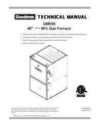
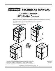
APPENDIX C UNIT DIMENSIONS47 1/2”73 1/4”38 13/16”*74 1/16”*6 Ton - 42 13/1648 3/16”11”4 7/8”17” 7 3/8”RETURN25”19 7/16”12”SUPPLY6 1/4”RETURN5 7/8”DRAINTHRU CURBLOCATIONEMBOSSFORTHRU THEBASEUTILITIESHORIZONTAL DISCHARGESUPPLY27 3/8”NOTE4 1/2”For horizontal discharge, remove thesupply and return duct covers and placethem over the vertical discharge return andsupply openings. Install with insulationfacing up, using the longer screwsprovided in the literature package.8 3/16”47 1/2”BOTTOM VIEW OF UNITVERTICAL DISCHARGE7 1/2”27
<strong>Goodman</strong> Manufacturing Company, L.P.5151 Felipe, Suite 500, Houston, TX 77056www.goodmanmfg.com www.amana-hac.com© 2010,2012 <strong>Goodman</strong> Manufacturing Company, L.P.28