NOTE: When inspecting the unit for transportation damage,remove all packaging materials. Recycle or dispose of thepackaging material according to local codes.PRE-INSTALLATION CHECKSCarefully read all instructions for the installation prior to installingunit. Ensure each step or procedure is understoodand any special considerations are taken into account beforestarting installation. Assemble all tools, hardware andsupplies needed to complete the installation. Some items mayneed to be purchased locally.UNIT LOCATIONWARNINGTO PREVENT POSSIBLE EQUIPMENT DAMAGE, PROPERTY DAMAGE,PERSONAL INJURY OR DEATH, THE FOLLOWING BULLET POINTS MUSTBE OBSERVED WHEN INSTALLING THE UNIT.IMPORTANT NOTE: Remove wood shipping rails prior toinstallation of the unit.ALL INSTALLATIONS:IMPORTANT NOTE: If a crankcase heater is used, the unitshould be energized 24 hours prior to compressor start up toensure crankcase heater has sufficiently warmed the compressor.Compressor damage may occur if this step is not followed.NOTE: Appliance is shipped from factory for vertical ductapplication.Proper installation of the unit ensures trouble-free operation.Improper installation can result in problems ranging fromnoisy operation to property or equipment damages, dangerousconditions that could result in injury or personal propertydamage and could void the warranty. Give this booklet to theuser and explain it’s provisions. The user should retain theseinstructions for future reference.• For proper operation and condensate drainage, theunit must be mounted level.• Do not locate the unit in an area where the outdoorair will be frequently contaminated by compoundscontaining chlorine or fluorine. Common sources ofsuch compounds include swimming pool chemicalsand chlorine bleaches, paint stripper, adhesives,paints, varnishes, sealers, waxes (which are not yetdried) and solvents used during construction andremodeling. Various commercial and industrialprocesses may also be sources of chlorine/fluorinecompounds.• To avoid possible illness or death of the buildingoccupants, do NOT locate outside air intake device(economizer, manual fresh air intake, motorized freshair intake) too close to an exhaust outlet, gas venttermination, or plumbing vent outlet. For specificdistances required, consult local codes.• Allow minimum clearances from the enclosure for fireprotection, proper operation, and service access (seeUnit Clearances). These clearances must bepermanently maintained.• When the unit is heating, the temperature of the returnair entering the unit must be between 50°F and 100°F.GROUND LEVEL INSTALLATIONS ONLY:• When the unit is installed on the ground adjacent tothe building, a level concrete (or equal) base isrecommended. Prepare a base that is 3” larger thanthe package unit footprint and a minimum of 3” thick.• The base should also be located where no runoff ofwater from higher ground can collect in the unit.ROOF TOP INSTALLATIONS ONLY:• To avoid possible property damage or personal injury,the roof must have sufficient structural strength to carrythe weight of the unit(s) and snow or water loads asrequired by local codes. Consult a structural engineerto determine the weight capabilities of the roof.• The unit may be installed directly on wood floors oron Class A, Class B, or Class C roof covering material.• To avoid possible personal injury, a safe, flat surfacefor service personnel should be provided.• Adequate clearances from the unit to any adjacentpublic walkways, adjacent buildings, building openingsor openable windows must be maintained inaccordance with National Codes.UNIT PRECAUTIONS• Do not stand or walk on the unit.• Do not drill holes anywhere in panels or in the baseframe of the unit. Unit access panels providestructural support.• Do not remove any access panels until unit has beeninstalled on roof curb or field supplied structure.• Do not roll unit across finished roof without priorapproval of owner or architect.• Do not skid or slide on any surface as this maydamage unit base. The unit must be stored on aflat, level surface. Protect the condenser coilbecause it is easily damaged.ROOF CURB INSTALLATIONS ONLY:Curb installations must comply with local codes and shouldbe done in accordance with the established guidelines of theNational Roofing Contractors Association.Proper unit installation requires that the roof curb be firmlyand permanently attached to the roof structure. Check foradequate fastening method prior to setting the unit on thecurb.4
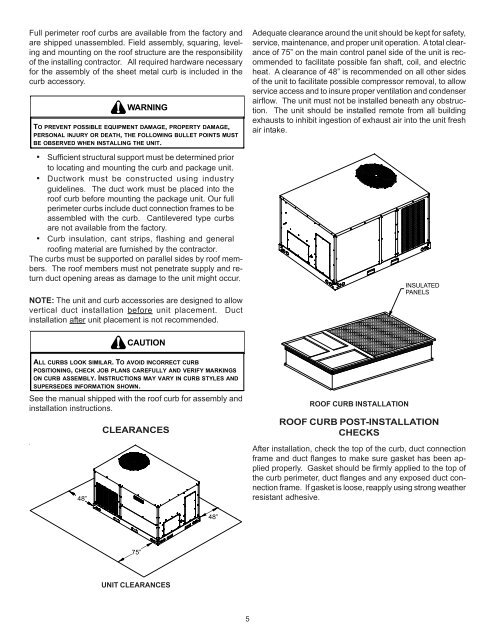
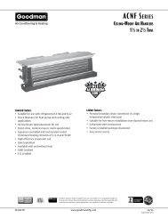
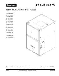
Full perimeter roof curbs are available from the factory andare shipped unassembled. Field assembly, squaring, levelingand mounting on the roof structure are the responsibilityof the installing contractor. All required hardware necessaryfor the assembly of the sheet metal curb is included in thecurb accessory.WARNINGTO PREVENT POSSIBLE EQUIPMENT DAMAGE, PROPERTY DAMAGE,PERSONAL INJURY OR DEATH, THE FOLLOWING BULLET POINTS MUSTBE OBSERVED WHEN INSTALLING THE UNIT.• Sufficient structural support must be determined priorto locating and mounting the curb and package unit.• Ductwork must be constructed using industryguidelines. The duct work must be placed into theroof curb before mounting the package unit. Our fullperimeter curbs include duct connection frames to beassembled with the curb. Cantilevered type curbsare not available from the factory.• Curb insulation, cant strips, flashing and generalroofing material are furnished by the contractor.The curbs must be supported on parallel sides by roof members.The roof members must not penetrate supply and returnduct opening areas as damage to the unit might occur.NOTE: The unit and curb accessories are designed to allowvertical duct installation before unit placement. Ductinstallation after unit placement is not recommended.Adequate clearance around the unit should be kept for safety,service, maintenance, and proper unit operation. A total clearanceof 75” on the main control panel side of the unit is recommendedto facilitate possible fan shaft, coil, and electricheat. A clearance of 48” is recommended on all other sidesof the unit to facilitate possible compressor removal, to allowservice access and to insure proper ventilation and condenserairflow. The unit must not be installed beneath any obstruction.The unit should be installed remote from all buildingexhausts to inhibit ingestion of exhaust air into the unit freshair intake.INSULATEDPANELSCAUTIONALL CURBS LOOK SIMILAR. TO AVOID INCORRECT CURBPOSITIONING, CHECK JOB PLANS CAREFULLY AND VERIFY MARKINGSON CURB ASSEMBLY. INSTRUCTIONS MAY VARY IN CURB STYLES ANDSUPERSEDES INFORMATION SHOWN.See the manual shipped with the roof curb for assembly andinstallation instructions.48”CLEARANCESROOF CURB INSTALLATIONROOF CURB POST-INSTALLATIONCHECKSAfter installation, check the top of the curb, duct connectionframe and duct flanges to make sure gasket has been appliedproperly. Gasket should be firmly applied to the top ofthe curb perimeter, duct flanges and any exposed duct connectionframe. If gasket is loose, reapply using strong weatherresistant adhesive.48”75”UNIT CLEARANCES5