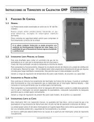
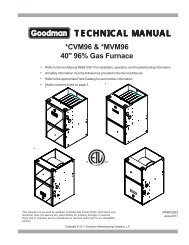
COOLINGEVAPORATORINDOORCOILSERVICE VALVESERVICE PORTCOMPRESSORDISTRIBUTOREXPANSION DEVICECHECK VALVEORIFICE SERVICEVALVESERVICE PORTACCUMULATORSERVICE PORTCHECK VALVEORIFICEREVERSING VALVECONDENSEROUTDOORCOILDEFROST CONTROLDuring operation the power to the circuit board is controlledby a temperature sensor, which is clamped to a feeder tubeentering the outdoor coil. Defrost timing periods of 30,60 and90 minutes may be selected by setting the circuit board jumperto 30, 60 and 90 respectively. Accumulation of time for thetiming period selected starts when the sensor closes (approximately31° F), and when the wall thermostat calls forheat. At the end of the timing period, the unit’s defrost cyclewill be initiated provided the sensor remains closed. Whenthe sensor opens (approximately 75° F), the defrost cycle isterminated and the timing period is reset. If the defrost cycleis not terminated due to the sensor temperature, a twelveminute override interrupts the unit’s defrost period.HEATINGCONDENSERINDOORCOILSERVICE VALVECOMPRESSORDISTRIBUTORCHECK VALVEORIFICE SERVICEVALVESERVICE PORTACCUMULATORSERVICE PORTCHECK VALVEORIFICEREVERSING VALVEDISTRIBUTOREVAPORATOROUTDOORCOILWhen the heat pump is on the heating cycle, the outdoor coilis functioning as an evaporator. The temperature of the refrigerantin the outdoor coil must be below the temperature ofthe outdoor air in order to extract heat from the air. Thus, thegreater the difference in the outdoor temperature and theoutdoor coil temperature, the greater the heating capacity ofthe heat pump. This phenomenon is a characteristic of aheat pump. It is a good practice to provide supplementaryheat for all heat pump installations in areas where the temperaturedrops below 45° F. It is also a good practice toprovide sufficient supplementary heat to handle the entireheating requirement should there be a component failure ofthe heat pump, such as a compressor, or refrigerant leak,etc.Since the temperature of the refrigerant in the outdoor coil onthe heating cycle is generally below freezing point, frost formson the surfaces of the outdoor coil under certain weather conditionsof temperature and relative humidity. Therefore, it isnecessary to reverse the flow of the refrigerant to provide hotgas in the outdoor coil to melt the frost accumulation. This isaccomplished by reversing the heat pump to the cooling cycle.At the same time, the outdoor fan stops to hasten the temperaturerise of the outdoor coil and lessen the time requiredfor defrosting. The indoor blower continues to run and thesupplementary heaters are energized.AIR FLOW ADJUSTMENTSThe drive on the supply fan is typically set in the middle of theRPM range. The drive motor sheave pitch diameter is fieldadjustable for the required airflow. Refer to “DriveAdjustments” section below.When the final adjustments are complete, the current drawof the motor should be checked and compared to the fullload current rating of the motor. The amperage must not exceedthe service factor stamped on the motor nameplate.The total airflow must not be less than that required for operationof the electric heaters or the furnace.If an economizer is installed, check the unit operating balancewith the economizer at full outside air and at minimumoutside air. Upon completion of the air flow balancing, werecommend replacing the variable pitched motor sheave witha properly-sized fixed sheave. A matching fixed sheave willprovide longer belt and bearing life and vibration free operation.Initially, it is best to have a variable pitched motor sheavefor the purpose of airflow balancing, but once the balancehas been achieved, fixed sheaves maintain alignment andminimize vibration more effectively. For direct drive units, movegreen wire for fan.NOTE: Never run CFM below 350 CFM per ton, evaporatorfreezing or poor unit performance is possible.PSC MOTORAdjust the CFM for the unit by changing the speed tap of theindoor blower motor at the EBTDR “com” connection with theone of the speed taps on “M1” or “M2” (Black-High Speed,Blue-Medium Speed, Red-Low Speed).X-13 MOTORAdjust the CFM for the unit by changing the position of thelow voltage leads on the motor terminal block. Green is forFan Only. Yellow is for Cooling and Heat Pump Heating. Referto Appendix A for blower performance at each speed tap.NOTE: If more than one lead is energized simultaneously,the motor will run at the higher speed.14
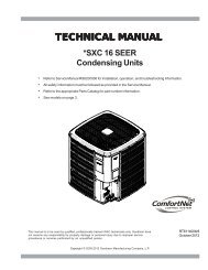
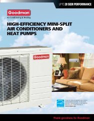
DRIVE ADJUSTMENTSMOTOR SHEAVE ADJUSTMENTSVL, VM, & 2VP VARIABLE PITCH KEY TYPE MOTOR SHEAVESThe driving and driven motor sheaves should be in alignmentwith each other and the shafts parallel.VL & VM SHEAVES ADJUSTMENT1. Loosen set screw “B” using a 5/32" Allen key.2. Making half or full turns from closed position, adjustsheave pitch diameter for desired speed. DO NOTOPEN MORE THAN FIVE FULL TURNS.3. Tighten set screw “B” securely over flat.4. Carefully put on belts and adjust belt tension. DO NOTFORCE BELTS OVER GROOVES.5. Ensure all keys are in place and the set screws tightbefore starting drive. Recheck set screws and belttension after 24 hours service.NOTE: Future adjustments should be made by loosening thebelt tension and increasing or decreasing the pitch diameterof the sheave by half or full turns as required. Readjust belttension before starting drive.VL & VMSHEAVE DIAGRAMNOTE: Do not operate sheave with flange projecting beyondthe hub end.BMAINTENANCEWARNINGHIGH VOLTAGE!DISCONNECT ALL POWER BEFORE SERVICING ORINSTALLING THIS UNIT. MULTIPLE POWER SOURCES MAYBE PRESENT. FAILURE TO DO SO MAY CAUSE PROPERTYDAMAGE, PERSONAL INJURY OR DEATH.WARNINGTO PREVENT PERSONAL INJURY OR DEATH DUE TO IMPROPERINSTALLATION, ADJUSTMENT, ALTERATION, SERVICE ORMAINTENANCE, REFER TO THIS MANUAL. FOR ADDITIONALASSISTANCE OR INFORMATION, CONSULT A QUALIFIED INSTALLER,SERVICE AGENCY OR THE GAS SUPPLIER.CCAUTIONSHEET METAL PARTS, SCREWS, CLIPS AND SIMILAR ITEMS INHERENTLYHAVE SHARP EDGES, AND IT IS NECESSARY THAT THE INSTALLER ANDSERVICE PERSONNEL EXERCISE CAUTION.The Self Contained Packaged Air Conditioner and Heat Pumpshould operate for many years without excessive service callsif the unit is installed properly. However it is recommendedthat the homeowner inspect the unit before a seasonal startup. The coils should be free of debris so adequate airflow isachieved. The return and supply registers should be free ofany obstructions. The filters should be cleaned or replaced.These few steps will help to keep the product up time to amaximum. The Service section that follows should help inidentifying problems if the unit does not operate properly.FILTERSCAUTIONTO PREVENT PROPERTY DAMAGE DUE TO FIRE AND LOSS OFEQUIPMENT EFFICIENCY OR EQUIPMENT DAMAGE DUE TO DUST AND LINTBUILD UP ON INTERNAL PARTS, NEVER OPERATE UNIT WITHOUT AN AIRFILTER INSTALLED IN THE RETURN AIR SYSTEM.Every application may require a different frequency of replacementof dirty filters. Filters must be replaced at least everythree (3) months during operating seasons.Dirty filters are the most common cause of inadequate heatingor cooling performance. Filter inspection should be madeat least every two months; more often if necessary becauseof local conditions and usage.Dirty throwaway filters should be discarded and replaced witha new, clean filter.Disposable return air filters are supplied with this unit. Seethe unit Specification Sheet or Technical Manual for the correctsize and part number. To remove the filters, remove thefilter access panel on return side of the unit.CABINET FINISH MAINTENANCEUse a fine grade automotive wax on the cabinet finish tomaintain the finish’s original high luster. This is especiallyimportant in installations with extended periods of direct sunlight.CLEAN OUTSIDE COIL (QUALIFIED SERVICER ONLY)The coil with the outside air flowing over it should be inspectedannually and cleaned as frequently as necessary to keep thefinned areas free of lint, hair and debris.CONDENSER, EVAPORATOR, AND INDUCED DRAFT MOTORSBearings on the air circulating blower motor, condenser motorand the combustion fan motor are permanently lubricated.No additional oiling is required.15