FPGA Power Reduction by Guarded Evaluation Considering Logic ...
FPGA Power Reduction by Guarded Evaluation Considering Logic ...
FPGA Power Reduction by Guarded Evaluation Considering Logic ...

You also want an ePaper? Increase the reach of your titles
YUMPU automatically turns print PDFs into web optimized ePapers that Google loves.
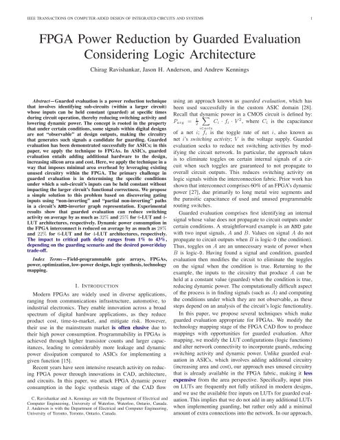
IEEE TRANSACTIONS ON COMPUTER-AIDED DESIGN OF INTEGRATED CIRCUITS AND SYSTEMS 2i0li1mxstC 1C 2Fig. 1: Cuts in circuit graph.identifying the conditions under which a given signal can beguarded is accomplished <strong>by</strong> analyzing properties of the logicsynthesis network, which is an And-Inverter Graph (AIG). Inparticular, we show that the presence of “non-inverting” and“partial non-inverting” paths in the AIG can be used to drivethe discovery of guarding opportunities. This structural-basedapproach to determining guarding opportunities proves to bevery efficient. Finally, we consider the introduction of differenttypes of guarding logic (as opposed to transparent latcheswhich are used for ASICs) to reduce unnecessary transientswitching.A preliminary version of a portion of this work appearedin [6]. In this extended journal version, we describe anadditional form of guarding that provides improved results,namely, guarding opportunities that arise from partial noninvertingpaths in the AIG. We also consider the consequencesof forcing guarded signals into the logic-1 state, rather thansolely forcing to the logic-0 state. Finally, we consider avariety of different <strong>FPGA</strong> logic block architectures beyondthat considered in the conference version. In particular, weexamine architectures with 4- and 6-input LUTs, as well asarchitectures with different numbers of LUTs per logic block.Results show that the benefit of guarding on power reductiondepends strongly on the underlying architecture of the target<strong>FPGA</strong>’s logic.The remainder of the paper is organized as follows: SectionII presents background and related work on technologymapping for <strong>FPGA</strong>s, power optimization, and describesguarded evaluation in the ASIC context. The proposed approachis described in Section III. An experimental studyappears in Section IV. Conclusions and suggestions for futurework are offered in Section V.II. BACKGROUNDA. <strong>FPGA</strong> Technology MappingHere we review the approach used <strong>by</strong> modern <strong>FPGA</strong>technology mappers, which are based on finding cuts inBoolean networks [26], [11]. The first step is to representthe combinational portion of a circuit as a directed acyclicgraph, G(V,E). Each node in G represents a logic function,and edges between nodes represent dependencies among logicfunctions. Before mapping commences, the number of inputsto each node must be less than the number of inputs of thetarget look-up-table (K).rFig. 1 illustrates cuts for a node x in a circuit graph. A cutfor x is a partition, (V,V ), of the nodes in the subgraph rootedat x, such that x ∈ V . For x’s cut C 1 in Fig. 1, V consists oftwo nodes, x and m. For x’s cut C 2 in the figure, V consistsof x, m, t, and l. A cut is called K-feasible if the number ofnodes in V that drive nodes in V is less than or equal to K.In the case of cut C 1 , there are 3 nodes that drive nodes inV and, the cut is 3-feasible. For a cut C =(V,V ), Inputs(C)represents the nodes in V that drive a node in V . For the cutC 1 in Fig. 1, Inputs(C 1 )={l, s, t}. Nodes(C) represents theset of nodes, V . In Fig. 1, Nodes(C 1 )={x, m}.For a K-feasible cut, C, the logic function of the subgraphof nodes, V , can be implemented <strong>by</strong> a single K-LUT. Thereason for this is that the cut is K-feasible and a K-LUTcan implement any function of up to K inputs. Hence, theproblem of finding all of the possible K-LUTs that generatea node’s logic function can be cast as the problem of findingall K-feasible cuts for the node. There are generally manyK-feasible cuts for each node in the network, correspondingto multiple potential LUT implementations.Enumerating all cuts for each node in the circuit graph is awell-studied problem with an established solution: The cuts foreach node in the network can be generated in a topologicalnetwork traversal, from inputs to outputs. As each node isvisited in the traversal, its complete set of K-feasible cutsis generated <strong>by</strong> merging cuts from its fanin nodes, using themethod described in [11], [26].Having computed the set of K-feasible cuts for each nodein the circuit graph, the graph is traversed in topologicalorder again. During this traversal, a “best cut” is chosen foreach node. The best cut reflects design optimization criteria,typically, area, power, delay or routability. The best cuts definethe LUTs in the technology mapped circuit.As mentioned, the first step in technology mapping is torepresent the network (combinational logic) as a directedacyclic graph such that the number of inputs to each nodeis less than or equal to K, the number of inputs of the targetLUT. A common data structure for this representation is anAnd-Inverter Graph (AIG). In an AIG, the circuit functionalityis represented solely as a network of 2-input AND gates andinverters. An example of an AND-inverter graph is shown inFig. 2. Observe that inverters are not represented explicitly asnodes in the graph, but rather as properties on graph edges.Research has demonstrated the utility of AIGs for many logicsynthesis transformations (e.g., [23], [18]). AIGs have alsoshown value for <strong>FPGA</strong> technology mapping as exemplified <strong>by</strong>the ABC tool [24], [22]. We therefore choose to investigateguarded evaluation within the ABC framework and to exploitthe properties of AIGs to aid in performing guarded evaluation.B. <strong>Power</strong>-Aware Mapping<strong>Power</strong>-aware cut-based technology mapping has been studiedrecently (e.g., [16], [14]). The core approach taken is tokeep signals with high switching activity out of the <strong>FPGA</strong>’sinterconnection network (which presents a high capacitiveload). This is achieved <strong>by</strong> costing cuts to encourage such highactivity signals to be captured within LUTs, leaving only low
IEEE TRANSACTIONS ON COMPUTER-AIDED DESIGN OF INTEGRATED CIRCUITS AND SYSTEMS 3zp q r sOriginal circuitzcomplementededgep q r sAND-inverter graph (AIG)Fig. 2: And-Inverter Graph (AIG) example.activity inter-LUT connections. A second aspect of powerawaremapping pertains to logic replication. <strong>Logic</strong> replicationis needed to achieve mappings with low depth (high speed).However, replication can increase power [16], as replicationincreases signal fanout and capacitance. Replications cantherefore be detected and cost accordingly, trading off theirpower “cost” with their depth “benefit”.evaluation at the RTL level for <strong>FPGA</strong>s [12]. Their approachproduced encouraging power reduction results <strong>by</strong>exploiting select signals on steering elements (multiplexers)to serve as guarding signals and is therefore limited tospecific types of circuits; e.g., datapath circuits in whichmultiplexers are used for resource sharing. Our approachis not directly comparable since we work on a synthesizedLUT network, avoid adding additional logic into thenetwork, and are not limited to using only the select lineson multiplexers to act as guarding signals.In contrast to prior works, which discover only a limitednumber of candidate guarding opportunities, our approachexposes many guarding opportunities through easy-to-computeproperties of the logic synthesis network. Furthermore, whileprior approaches required additional hardware to be added tothe design (e.g., transparent latches in Fig. 3), our approachincurs no overhead (in terms of LUT count) <strong>by</strong> usingexisting yet unused <strong>FPGA</strong> circuitry, although additionalwires are required to perform guarding.C. <strong>Guarded</strong> <strong>Evaluation</strong>Tiwari et al. [28] first described important techniquesfor guarded evaluation in ASICs. The key idea is shownin Fig. 3. In Fig. 3(a), a multiplexer is shown receiving itsinputs from a shifter and a subtraction unit, depending on thevalue of select signal Sel. Fig. 3(b) shows the circuit afterguarded evaluation. Guard logic, comprised of transparentlatches, is inserted before the functional units. The latchesare transparent only when the output of the correspondingfunctional unit is selected <strong>by</strong> the multiplexer, i.e., dependingon signal Sel. When the output of a functional unit is notneeded, the latches hold its input constant, eliminating toggleswithin the unit. Here, one can view Sel as the “guardingsignal”. Tiwari applied this concept to gate-level networks,where the difficulty was in determining which signals couldbe used as guarding signals for particular sub-circuits. Tiwariused binary decision diagrams to discover logical implicationsthat permit certain sub-circuits to be disabled at certain times.Abdollahi et al. proposed using guarded evaluation in ASICsto attack both leakage and dynamic power [3]. The guardingsignals were used to drive the gate terminals of NMOS sleeptransistors incorporated into CMOS gate pull-down networks,putting sub-circuits into low-leakage states when their outputswere not needed. Howland and Tessier studied guardedABdataregistersShifterSubtract01SelABSel=0data Sel=1registerstransparent latchesShifterSubtractguard logica) Before guarded evaluation b) After guarded evaluationFig. 3: <strong>Guarded</strong> evaluation (adapted from [28]).01SelD. Gating Inputs and Non-Inverting AIG PathsTechnology mapping covers the circuit AIG with LUTs –each LUT in the mapped network implements a portion of theunderlying AIG logic functionality. A recent work suggested anew <strong>FPGA</strong> architecture using properties of the AIG to discovergating inputs to LUTs [7]. A gating input to a LUT has theproperty that when the input is in a particular logic state(either logic-0 or logic-1), then the LUT output is logic-0,irrespective of the logic states of the other inputs to the LUT.We borrow the idea of gating inputs for guarded evaluationand therefore briefly review the concept here.Fig. 4 gives an example of a LUT and the correspondingportion of a covered AIG. The logic function implemented <strong>by</strong>the LUT is: Z = I ·J ·K ·Q · M. Examine the AIG path fromthe input I to the root gate of the AIG, Z. The path comprisesa sequence of AND gates with none of the path edges beingcomplemented. Recall that the output of an AND gate is logic-0 when either of its inputs is logic-0. For the path from I toZ, when I is logic-0, the output of each AND gate along thepath will be logic-0, ultimately producing logic-0 on the LUToutput. We therefore conclude that I is a gating input to theLUT. The LUT in Fig 4, in fact, has three gating inputs, I,J, and K. Input J is the same form as input I in that thereexists a path of AND gates from J to root gate Z and none ofthe edges along the path are inverted.Observe, however, that the situation is slightly different forinput K. For input K, the “frontier” edge crossing into theLUT is inverted, however, aside from this frontier edge, theremaining edges along the path from K to the root node Z are“true” edges. This means that when K is logic-1, the outputof the AND gate it drives will be logic-0, eventually makingthe LUT’s output signal Z logic-0. K is indeed a gating input,though it is K’s logic-1 state (rather than its logic-0 state) thatcauses the LUT output to be logic-0. In contrast with inputsI,J and K, LUT inputs Q and M are not gating inputs tothe LUT as neither logic state of these inputs causes the LUToutput to be logic-0. The question of which inputs are gating
IEEE TRANSACTIONS ON COMPUTER-AIDED DESIGN OF INTEGRATED CIRCUITS AND SYSTEMS 6traversal is applied to qualify multi-fanout LUTs as guardingcandidates. In general, for a guarding signal G driving a LUTZ, we can safely use G to guard any LUT within Z’s fanoutfreefanin cone.It is worthwhile to highlight an important difference betweenour approach and the prior ASIC approach, shown inFig. 3. In Fig. 3, transparent latches are used to hold inputs toblocks constant while the blocks are guarded. Our approach,on the other hand, takes the logical AND or logical OR of anexisting LUT function with the guarding signal, making theLUT output logic-0 or logic-1 while guarded. Our methodrequires the guarded LUT to have additional inputs that arefree to insert the guarding signal, which constrains someguarding opportunities. Nonetheless, our results show that asignificant number of guards were inserted effectively reducingdynamic power. Moreover, our method has the advantageof adding no LUTs to the circuit. The only overhead isfor wires added to connect guarding signals to the faninof the guarded LUTs.It is also worth mentioning that LUTs in today’s commercial<strong>FPGA</strong>s have 6 inputs [5], [29], which provide better speedperformance than the 4-LUTs used traditionally. Many logicfunctions in circuits require less than 6 variables and consequently,LUTs in mapped circuits commonly have unusedinputs. A recent work from Xilinx demonstrated that incommercial 6-LUT circuits, only 39% of the LUTs in themappings use all 6 inputs [13]. A similar observation wasmade earlier in [17] when describing the Altera Stratix IIarchitecture where it was observed that only 36% of theLUTs in a mapped set of designs required full 6-LUTs.The considerable number of LUTs with unused inputs bodeswell for our guarding scheme.B. Creating Guarding Opportunities During MappingHaving introduced how guarded evaluation can be appliedto a mapped network, we now consider the influence of themapping step itself on guarding. We aim to encourage thecreation of LUT mapping solutions containing “good”guarding opportunities, while maintaining the quality ofother circuit criteria, such as area and depth. We proposea cost function for cuts to reflect cut value from the guardingperspective.For a set of inputs to a cut C, Inputs(C), defineGating[Inputs(C)] to be the subset of inputs that are gatingLUT M. . .LUT ZLUT Q. . .GLUT Lgating inputto LUT ZLUT G. . . . . .. . .Fig. 8: Guarding with reconvergent fanout.LUT L. . . .G. . . . . . . .. . . .Fig. 9: Illustration of how guarding can create a combinationalloop.inputs, as defined in Section II-D. We define a GuardCost fora cut, such that minimization of GuardCost will encouragethe creation of mapping solutions containing high-qualityguarding opportunities, while at the same time minimizing thedynamic power of the mapped network:GuardCost(C) = 1+∑ i ∈ Inputs(C) α(i)1+|Gating[Inputs(C)]|where α(i) represents the switching activity on LUT input i.The numerator of (2) tallies the switching activities on cutinputs, minimizing activity on inter-LUT connections in themapped network. Higher input activities yield higher values ofGuardCost. A similar approach to activity minimization hasbeen used in other works on power-aware <strong>FPGA</strong> technologymapping [16], [14]. The denominator of (2) reflects the desireto have LUTs with gating inputs (i.e., inputs that drive noninvertingpaths in the AIG). The signals on such inputscan naturally be used to guard other LUTs, as described inSection III-A. Cuts with higher numbers of such non-invertingpath inputs will have lower values of (2).C. Post-Mapping <strong>Guarded</strong> <strong>Evaluation</strong>Following mapping, the circuit is represented as a networkof LUTs. Consider a guarding option, O, comprising L as thecandidate LUT to guard, and G being the candidate guardingsignal (produced <strong>by</strong> some other LUT in the design). We scoreguarding option O as follows:Score(O) =|Outputs(L)|·α(L) · P (L, G)1+α(G)where |Outputs(L)| represents the fanout of LUT L; α(L)and α(G) are the switching activities on L and G’s outputs,respectively; and P (L, G) is the fraction of time thatG spends at the value that gates L. The numerator of(3) represents the benefit of guarding, which increases inproportion to L’s fanout, its activity and the fraction of timeG serves to gate L. The more time that G spends at itsgating value, the higher the likely activity reduction on L.The denominator of (3) represents the cost of guarding, whichis an increase of G’s fanout (and likely capacitance). The costis proportional to the activity of signal G, as it is less desirableto increase the fanout of high activity signals. Higher values of(3) are associated with what we expect will be better guardingcandidates. For a mapped network, we capture all possibleguarding options in an array and sort the array in descendingorder of each option’s score, as computed through (3). The(2)(3)
IEEE TRANSACTIONS ON COMPUTER-AIDED DESIGN OF INTEGRATED CIRCUITS AND SYSTEMS 9(a)(a)(b)(b)Fig. 11: Average reduction in switching activity (normalized)across a benchmark suite of 20 designs for area-orientedmapping: (a) 6-LUT architectures; (b) 4-LUT architectures.B. Switching Activity ResultsThe reduction in total switching activity for area-orientedmapping (using all different mapping techniques) is shown inFig. 11(a) and Fig. 11(b) for 6-LUT and 4-LUT architectures,respectively. Reported numbers represent the total switchingactivity averaged across a benchmark suite of 20 circuitsnormalized to the results obtained using the priority cut-basedmapper.In both Fig. 11(a) and (b), the left-most bar shows totalswitching activity for priority cut-based mapping [24] andrepresents the baseline result. The second bar shows activityvalues for WireMap [13]. On average, WireMap reduces totalswitching activity <strong>by</strong> 10% and 3% on average for 6-LUT and4-LUT architectures, respectively. The third bar shows resultsfor activity-driven WireMap; total switching activity is furtherreduced <strong>by</strong> 4% and 3% for 6-LUT and 4-LUT architectures,respectively.The fourth bar in Fig. 11 shows results for guarding withonly gating inputs (c.f. Section II-D) without any considerationof trimming inputs (c.f. Section II-E) or non-obvious don’tcares (c.f. Section III-D). Further, the fourth bar does notconsider the guard insertion based on static probabilities, butonly inserts AND gates (c.f. Section III-A) to force signalsto logic-0 when guarded. Guarding with only gating inputsand AND gates reduces the total switching activity <strong>by</strong> anadditional 4% for both 6-LUT and 4-LUT architectures whencompared to activity-driven WireMap. The use of trimminginputs significantly improves results as shown in the fifth barin Fig. 11(a) and (b); the total switching activity is furtherreduced <strong>by</strong> an additional 4% and 5% for 6-LUT and 4-LUTFig. 12: Average reduction in switching activity (normalized)across a benchmark suite of 20 designs for depth-oriented anddepth-relaxed mapping: (a) 6-LUT architectures; (b) 4-LUTarchitectures.architectures, respectively, when compared to guarding withonly gating inputs. Significantly more guarding opportunitieswere revealed when trimming inputs (i.e., partial non-invertingpaths) are considered.The sixth bar shows guarding with gating and trimminginputs while considering the guarding value and the staticprobability of the guarded LUT when determining whether toguard with an AND gate or an OR gate (c.f. Section III-A). Recallthat, intuitively, <strong>by</strong> considering different types of guardinglogic, it should be true that unnecessary toggling is reducedand, consequently, a further reduction in switching activitycan be obtained. However, as demonstrated <strong>by</strong> the sixth barin Fig. 11(a) and (b), we see that results are worsened <strong>by</strong>2 − 3% for both 6-LUT and 4-LUT architectures. This resultis analyzed and considered further in Section IV-D.Finally, the last three bars (bars 7 through 9) in Fig. 11(a)and (b) shows results for guarding with consideration fornon-obvious “don’t cares” under the same conditions as theprevious three bars (bars 4 through 6). We see a similarpattern to bars 4 through 6 with the exception that the useof non-obvious don’t cares serve to further improve results.If we consider all different mapping strategies, we can seethat it is possible to obtain significant reductions in totalswitching activity compared to the priority cut-based mapper;with minor modifications to WireMap and <strong>by</strong> proper selectionof guarding techniques, average reductions of 32% and 25% intotal switching activity can be obtained for 6-LUT and 4-LUTarchitectures, respectively.Fig. 12(a) and (b) show the reductions in total switchingactivity for 6-LUT and 4-LUT architectures, respectively, oncedepth optimization is taken into account. During the insertionof guards, an additional constraint is enforced such that the
IEEE TRANSACTIONS ON COMPUTER-AIDED DESIGN OF INTEGRATED CIRCUITS AND SYSTEMS 11the present implementation, the CEC is always performedon the entire network, but it in fact only needs to beperformed on certain points in the fanout of the guardedLUTs. More judicious application of don’t cares can beconsidered. Finally, it is likely that the guarding with don’tcares could be better integrated with scalable don’t careanalysis.(a)(b)Fig. 14: Post-packing statistics on LB count and fanin fordepth-oriented mapping: (a) 6-LUT architectures; (b) 4-LUTarchitectures. Results show (i) LB counts (normalized), (ii)average LB fanin for the case of 4 LUTs/LB.figure are encouraging, as guarding adds connections tothe mapped netlist, yet the additional connections appearto have a modest impact post-packing.We consider runtimes for guarding as follows. Withoutexploiting don’t cares, the worst runtime encountered was46 seconds 6 . The breakdown of runtime was 33.5% forcombinational loop checks, 62.2% for simulation, and 2.1%for guard identification. The small amount of remainingruntime was overhead. Both the simulation runtimes andcombinational loop checking can be improved. For example,combinational loops could be checked via node levelsrather than via depth-first search in many cases. Similarly,less simulation or incremental simulation could be used.Hence, guarding without don’t cares is expected to scaleto larger designs. When don’t cares are used, however, theruntime situation changes. The worst runtime encounteredwas ∼8000 seconds. Here, only ∼3% of the runtime wastaken for simulation, combinational loop checking andguard identification. Almost all the runtime was used toperform combinational equivalence checking (CEC) viaSAT solving. However, it is important to recognize that, asour goal was to evaluate the power benefits of guarding, wemade no effort to reduce runtime. The runtime situationis straightforward to improve in a number of ways: In6 The platform was a 3.2 GHz Intel i7 PC running Ubuntu Linux v11.10.The particular design was clma which, when mapped to 6-LUTs, required∼3000 LUTs.C. <strong>Power</strong> ResultsWhile the results above demonstrate a benefit to switchingactivity, dynamic power scales with the product of activityand capacitance. <strong>Guarded</strong> evaluation increases the fanout ofsignals in the network, likely increasing their capacitance andpower. Consequently, it is not adequate to focus solely onactivity reduction to evaluate the benefit of the technique—actual power measurements after placement and routing areuseful.Furthermore, modern <strong>FPGA</strong> architectures cluster LUT/FFpairs into LBs. Since guarded evaluation reduces the switchingactivity on wires with the cost of increased fanout of somesignals, it is relevant to analyze the impact of this approachon architectures with different cluster sizes. The expectation isthat more heavily clustered architectures would benefit fromguarding the most since LUTs with identical guards (in effect,shared input signals) would tend to be placed into the sameLB. The consequence is that the additional wires added <strong>by</strong>guarding will not impact inter-clustering routing significantly;i.e., the fanout when measured in terms of the number of logicblocks will not increase as much when guarding is targetedtowards heavily clustered architectures.Fig. 15(a) and (b) gives the average power consumed inthe <strong>FPGA</strong> interconnect for area-oriented mapping for 6-LUTand 4-LUT architectures of different cluster sizes, respectively.The results consider post-routing interconnect capacitanceon architectures with cluster sizes of 1 (flat), 4 and 10.The pattern is similar to that shown when considering totalswitching activity. The best results are obtained when bothgating and trimming inputs were used, with considerationto non-obvious don’t-cares, and guarding was done usingonly AND gates. For 6-LUT architectures, Fig. 15(a) showsan average improvement of 14%, 28% and 27% for clustersizes of 1, 4 and 10, respectively, relative to priority cutsbasedmapping. For 4-LUT architectures, Fig. 15(b) shows anaverage improvement of 14%, 22% and 21% for cluster sizesof 1, 4 and 10, respectively. From these experimental results,it appears that more heavily clustered architectures benefit themost from guarding. This observation is considered further inSection IV-D.Fig. 16(a) and (b) show the results for depth-orientedand depth-relaxed mapping. Once again, the best results areproduced when guarding with gating and trimming inputswhile considering non-obvious don’t cares, which is consistentwith the observations made during the investigation of totalswitching activity. Similar to area-oriented mapping, the mostbenefit is seen for the more heavily clustered architectures.Specifically, For 6-LUT architectures, Fig. 16(a) shows reductionsof 15%, 16% and 15% for clusters sizes of 1, 4 and 10,
IEEE TRANSACTIONS ON COMPUTER-AIDED DESIGN OF INTEGRATED CIRCUITS AND SYSTEMS 14Mapping FlowNormalizedCritical Path Delay1x6 4x6 10x6Activity-DrivenWireMap 1.00 1.00 1.00Gating 1.18 1.20 1.20Trimming 1.23 1.27 1.30Gating (DC) 1.31 1.37 1.42Trimming (DC) 1.31 1.39 1.43Mapping Flow(a)NormalizedCritical Path Delay1x6 4x6 10x6Activity-DrivenWireMap 1.00 1.00 1.00Gating 1.01 1.00 1.01Trimming 1.01 1.00 1.01Gating (DC) 1.02 1.01 1.02Trimming (DC) 1.03 1.02 1.02Gating (DC +20%) 1.14 1.16 1.17Trimming (DC +20%) 1.11 1.13 1.15(b)Fig. 17: Critical path delays for several key mapping techniquesto understand the impact of guarding on performance:(a) area-oriented mapping; (b) delay-oriented mapping.TABLE V: Comparison of the number of inserted guardsusing gating+trimming inputs when using only AND gatesversus using AND gates + OR gates to guard.Design Trimming Trimming Trimming Trimmingwith OR (DC) with OR (DC)alu4 95 75 187 153apex2 36 23 115 117apex4 10 9 47 40bigkey 0 0 0 0clma 843 505 790 491des 9 5 37 28diffeq 3 3 81 46dsip 1 1 1 1elliptic 49 49 83 50ex1010 15 95 95 148ex5p 15 11 64 62frisc 18 196 125 252misex3 54 43 173 158pdc 72 93 213 210s298 36 69 96 155s38417 84 88 128 142s38584.1 68 69 105 131seq 34 23 105 111spla 86 87 209 170tseng 9 2 64 24Average 76.9 72.3 136 124.5TABLE IV: Number of guarding options and inserted guardsfor two different guarding strategies.D. DiscussionDesign Gating TrimmingOptions Inserted Options Insertedalu4 3880 86 4071 95apex2 6720 34 6873 36apex4 1862 8 1866 10bigkey 0 0 0 0clma 5965 243 10403 843des 153 6 184 9diffeq 8 1 17 3dsip 224 1 224 1elliptic 658 49 658 49ex1010 12125 15 12125 15ex5p 812 15 812 15frisc 641 15 662 18misex3 3221 48 3270 54pdc 9169 48 9312 72s298 1252 18 1527 36s38417 656 71 767 84s38584.1 356 36 584 68seq 2027 27 2111 34spla 7192 51 7334 86tseng 11 4 21 9Average 2846.6 38.8 3141.1 76.9There were several interesting results seen during experimentationof the guarded evaluation approach and these resultsare further investigated in this section.1) Use of Gating and Trimming Inputs: The previousnumerical results demonstrated that the use of trimming inputsfound through the consideration of partial non-inverting pathssignificantly improved results. Table IV shows results on aper design basis when targeting depth-oriented mapping and6-LUT architectures. In particular, Table IV shows the numberof guarding options computed and the number of actualinserted guards for: 1) guarding using only gated inputs; and2) guarding using gated and trimming inputs. It can clearly beseen that the use of trimming inputs found through partial non-inverting paths significantly improve the number of guardingcandidates and, in turn, results in the insertion of more guardsleading to a larger improvement in total switching activity andlower power dissipation. Although not shown, the results areeven more pronounced with non-obvious don’t cares are takeninto account during guarding.2) Use of OR Gates as Guard <strong>Logic</strong>: An apparentlycounter-intuitive result was observed when attempting to accountfor the static probability of a signal when insertingguards; recall the intention was to insert either an AND gateor an OR where appropriate to avoid unnecessary toggles.Counterinituitively, it did not prove effective to use OR gates,as demonstrated <strong>by</strong> the numerical results previously presented.Analysis demonstrated that the insertion of an OR gate (whenappropriate) based on static probability was having a positiveeffect, but only on a local level. In other words, the selectionof either an AND gate or an OR or based on static probabiltiyresulted in reduced switching activity for the current signalbeing guarded.However, further investigation showed that the use of ORgates resulted in fewer total inserted guards. Table V showsthe number of guards inserted when signal probabilities aretaken into account; these results are presented for 6-LUTarchitectures and depth-oriented mappings. In almost all cases,accounting for signal probabilities and choosing an appropriategate type (AND or OR) resulted in fewer inserted guards whencompared to simply inserting an AND gate and forcing a signalto logic-0. In the course of the algorithm, we observed thatthe insertion of OR gates was creating a different rankingof guarding options resulting in a different order in whichguards were inserted and free LUT inputs were “used up”. Itis a possibility that a different benchmark suite or a differentscoring function for guarding candidates would have resultedin a different outcome.
IEEE TRANSACTIONS ON COMPUTER-AIDED DESIGN OF INTEGRATED CIRCUITS AND SYSTEMS 15TABLE VI: Increase of the average number of additionalconnections that require inter-cluster routing due to guarding(depth-oriented mapping using only gating inputs for guarding).Architecture Avg Num Avg Num(Guards) (Inter-cluster)Signals1x6 38.8 38.84x6 38.8 33.510x6 38.8 33.11x4 45.3 45.34x4 45.3 11.610x4 45.3 12.13) Architectural Analysis: Typically, clustered architecturestended to benefit more from the application of guardedevaluation (c.f. Figs. 15 and 16). To better understand thisphenomenon, we conducted additional investigation. Despitenot impacting the LUT count of the mapped network, guardedevaluation does require the insertion of additional signals.Consequently, guarded evaluation results in networks withadditional connections that require routing. For example, ifwe refer to Table IV, we see that guarding using only gatinginputs (and depth-oriented mapping) required, on average,an additional 38.8 connections per design for 6-LUT architectures.Although not shown, guarding using only gatinginputs (and depth-oriented mapping) required, on average, anadditional 45.3 connections per design when considering 4-LUT architectures.We considered how these additional connections wererouted. In an architecture with a cluster size of 1 (i.e., flat),these connections must be routed through global interconnect;i.e., inter-cluster routing. However, in a clustered architecture,these additional signals could be absorbed into the clusters;i.e., only intra-cluster routing is required. Clearly, when interclusterrouting is required, the additional power consumptionof these additional connections could out-weigh the benefitsof guarding due to the increased capacitance of inter-clusterversus intra-cluster routing.Table VI shows the average number of additional connectionsadded to the networks due to guarding (using only gatinginputs) after clustering is performed and LUTs are packedinto LBs. In other words, Table VI shows the actual numberof additional connections which require inter-cluster routing.Clearly, for flat architectures, the average number of extrainter-cluster signals is equal to the average number of guardsinserted. But, for clustered architectures, the average numberof inter-cluster signals is reduced. Referring back to Figs. 15and 16 we can observe this trend; when those connectionsinserted due to guarding are effectively absorbed into theLBs, more significant power reductions are observed whencompared to a flat architecture.V. CONCLUSIONS AND FUTURE WORK<strong>Guarded</strong> evaluation reduces dynamic power <strong>by</strong> identifyingsub-circuits whose inputs can be held constant at certain timesduring circuit operation, eliminating toggles within the subcircuits.We have proposed the adaption of guarded evaluationto make it suitable for <strong>FPGA</strong>s. Specifically, we have shownthat guarding can be applied after technology mapping withoutany increase to the overall area (measured in terms of the numberof LUTs) of the network; it is only necessary to add extraconnections into the network in order to perform the guarding.Increases in area are avoided <strong>by</strong> exploiting the availability ofunused inputs on LUTs and the existing circuitry inside theLUTs to perform guarding. Numerical results demonstrate theefficacy of our proposed techniques and show that guardedevaluation is effective for <strong>FPGA</strong> designs.Additionally, we have proposed a structural technique toidentify guarding candidates based on the ideas of noninvertingand partial non-inverting paths; the use of partialnon-inverting paths was demonstrated to significantly improvethe availability of guarding options and, in turn, improve thereduction in both total reduction in total switching activityand reduction in total dynamic power dissipation. Finally,we considered the impact on different <strong>FPGA</strong> architectures.We discovered that, more often than not, guarded evaluationwas most effective for clustered architectures. Analysisdemonstrated that this was due to the guarding signals being“absorbed” into the logic block clusters.Possible directions for future work would include theconsideration of alternative scoring schemes to improvethe guard selection. Although the structural identificationof guards is extremely fast, the scalability of the algorithm— both without and with don’t cares — can beimproved. Looking for additional techniques for easily identifyingguarding candidates beyond the use of non-invertingand partial non-inverting paths. More guarding candidates,for example, might serve to improve guarding results duringdepth-oriented mapping when many candidates are discardeddue to violation of depth constraints. Closer integration withclustering and placement would serve to improve results.Guarding after clustering (or placement) would permit animproved scoring function which would not only allowfor a more intelligent decision regarding dynamic powerconsumption, but would also allow for a more intelligentdecision with respect to cluster feasibility and designroutability; e.g., any benefit in dynamic power reductioncould be weighted against the addition of an inter-clusterwire. Lastly, it would be valuable to consider a newerversion of VPR [19], [20] once power calculation tools areavailable for these versions of VPR. This would enable aninvestigation of guarded evaluation on even more realistic<strong>FPGA</strong> architectures (such as those supporting fracturableLUTs) as well as enable larger sets of realistic designs tobe considered. Various architectural factors might requireadditional modifications to the scoring function and thedecision as to whether or not a guard should be inserted.Alternatively, it would be valuable to consider the powerbenefits of guarded evaluation for a commerical <strong>FPGA</strong>using, for example, the Altera QUIP framework [2].REFERENCES[1] ABC – a system for sequential synthesis and verification.
IEEE TRANSACTIONS ON COMPUTER-AIDED DESIGN OF INTEGRATED CIRCUITS AND SYSTEMS 16http://www.eecs.berkeley.edu/∼alanmi/abc/, 2009.[2] Quartus-II university interface program.http://www.altera.com/education/univ/research/unv-quip.html, 2009.[3] A. Abdollahi, M. Pedram, F. Fallah, and I. Ghosh. Precomputationbasedguarding for dynamic and leakage power reduction. In IEEE Int’lConf. on Computer Design, pages 90–97, 2003.[4] E. Ahmed and J. Rose. The effect of LUT and cluster size on deepsubmicro<strong>FPGA</strong> performance and density. In ACM/SIGDA InternationalSymposium on Field Programmable Gate Arrays, pages 85–94, Monterey,CA, 2002.[5] Altera, Corp., San Jose, CA. Stratix-III <strong>FPGA</strong> Family Data Sheet, 2008.[6] J. Anderson and C. Ravishankar. <strong>FPGA</strong> power reduction <strong>by</strong> guardedevaluation. In Proc. <strong>FPGA</strong>, pages 157–166, 2010.[7] J. Anderson and Q. Wang. Improving logic density through synthesisinspiredarchitecture. In IEEE International Conference on FieldProgrammable <strong>Logic</strong> and Applications, pages 105 – 111, Prague, CzechRepublic, 2009.[8] J. Anderson and Q. Wang. Area-efficient <strong>FPGA</strong> logic elements:Architecture and synthesis. In IEEE/ACM Asia and South Pacific DesignAutomation Conference, pages 369–375, 2011.[9] V. Betz and J. Rose. VPR: A new packing, placement and routing toolfor <strong>FPGA</strong> research. In Int’l Workshop on Field Programmable <strong>Logic</strong>and Applications, pages 213–222, 1997.[10] S. Chatterjee, A. Mishcenko, R. Brayton, X. Wang, and T. Kam.Reducing structural bias in technology mapping. In Int’l Workshop on<strong>Logic</strong> Synthesis, 2005.[11] J. Cong, C. Wu, and E. Ding. Cut ranking and pruning: Enabling Ageneral and efficient <strong>FPGA</strong> mapping solution. In Int’l Symp. on Field-Programmable Gate Arrays, pages 29–35, 1999.[12] D. Howland and R. Tessier. RTL dynamic power optimization for<strong>FPGA</strong>s. In IEEE Midwest Symp. on Circuits and Systems, pages 714–717, 2008.[13] S. Jang, B. Chan, K. Chung, and A. Mishchenko. Wiremap: <strong>FPGA</strong>technology mapping for improved routability and enhanced LUT merging.ACM Trans. on Reconfigurable Technology and Systems, 2(2):1–24,2009.[14] S. Jang, K. Chung, A. Mishchenko, and R. Brayton. A power optimizationtoolbox for logic synthesis and mapping. In IEEE InternationalWorkshop on <strong>Logic</strong> Synthesis, San Francisco, CA, 2009.[15] I. Kuon and J. Rose. Measuring the gap between <strong>FPGA</strong>s and ASICs.IEEE Trans. On CAD, 26(2):203–215, February 2007.[16] J. Lamoureux and S.J.E. Wilton. On the interaction between poweraware<strong>FPGA</strong> CAD algorithms. In IEEE/ACM Int’l Conf. on Computer-Aided Design, pages 701–708, 2003.[17] David Lewis, Elias Ahmed, Gregg Baeckler, Vaughn Betz, MarkBourgeault, David Cashman, David Galloway, Mike Hutton, Chris Lane,Andy Lee, Paul Leventis, Sandy Marquardt, Cameron McClintock,Ketan Padalia, Bruce Pedersen, Giles Powell, Boris Ratchev, SrinivasReddy, Jay Schleicher, Kevin Stevens, Richard Yuan, Richard Cliff, andJonathan Rose. The stratix ii logic and routing architecture. In <strong>FPGA</strong>,pages 14–20, 2005.[18] A. Ling, J. Zhu, and S. Brown. Delay driven AIG restructuring usingslack budget management. In ACM/IEEE Great Lakes Symp. on VLSI,pages 163–166, 2008.[19] J. Luu, J. Anderson, and J. Rose. Architecture description and packingfor logic blocks with hierarchy, modes and complex interconnect. In<strong>FPGA</strong>, pages 227–236, 2011.[20] J. Luu, I. Kuon, P. Jamieson, T. Cambell, A. Ye, M. Fnag, and J. Rose.VPR 5.0: <strong>FPGA</strong> CAD and architecture exploration tools with singledriverrouting, heterogeneity and process scaling. In <strong>FPGA</strong>, pages 133–142, 2009.[21] A. Marquardt, V. Betz, and J. Rose. Timing-driven placement for<strong>FPGA</strong>s. In ACM Int’l Symp. on Field-Programmable Gate Arrays, pages203–213, 2000.[22] A. Mishchenko, R. Brayton, J.-H. R. Jiang, and S. Jang. Scalable don’tcare-basedlogic optimization and resynthesis. In Proc. <strong>FPGA</strong>, pages151–160, 2009.[23] A. Mishchenko, S. Chatterjee, and R. Brayton. DAG-aware AIGrewriting: A fresh look at combinational logic synthesis. In ACM/IEEEDesign Automation Conf., pages 532–536, 2006.[24] A. Mishchenko, S. Cho, S. Chatterjee, and R. Brayton. Combinationaland sequential mapping with priority cuts. In Proc. ICCAD, pages 354–361, 2007.[25] K. Poon, A. Yan, and S. Wilton. A flexible power model for <strong>FPGA</strong>s.In Int’l Conf. on Field-Programmable <strong>Logic</strong> and Applications, pages312–321, 2002.[26] M. Schlag, J. Kong, and P.K. Chan. Routability-driven technologymapping for lookup table-based <strong>FPGA</strong>s. IEEE Trans. on CAD, 13(1):13–26, 1994.[27] L. Shang, A. Kaviani, and K. Bathala. Dynamic power consumption ofthe Virtex-II <strong>FPGA</strong> family. In ACM Int’l Symp. on Field-ProgrammableGate Arrays, 2002.[28] V. Tiwari, S. Malik, and P. Ashar. <strong>Guarded</strong> evaluation: pushingpower management to logic synthesis/design. IEEE Trans. on CAD,17(10):1051–1060, October 1998.[29] Xilinx, Inc., San Jose, CA. Virtex-5 <strong>FPGA</strong> Data Sheet, 2007.[30] S. Yang. <strong>Logic</strong> synthesis and optimization benchmarks. version 3.0.Technical report, Microelectronics Center of North Carolina, 1991.VI. REVIEWER COMMENTS WITH REPLIESWe would like to thank the reviewer’s for their comments.It is very clear that all of the reviewers took the time to readour submission carefully and provide useful feedback. Pleasefind below our replies to the various comments along with anindication of any changes made to the manuscript as a resultof the comments. Any actual changes to the manuscript weremade in blue text.A. Reviewer: 1Overall a good paper with nice ideas.Thank you!Major issues:1) Appears to be written with the attitude that LUT countis the only relevant area metric. I explain below why this iswrong. I require 3 types of fixes to address this. See below.We will address these issues in subsequent comments.2) Missing reference to Lewis et.al. from <strong>FPGA</strong>’03Corroborates the Xilinx data that there are spare inputs. Butit also points out in detail why you have to pay attentionto compatibility between pairs of LUTs when targettingcommercial <strong>FPGA</strong>s. Future work should use tools such asupcoming VTR which can properly model this.We have added the reference to Lewis et al. From thebibtex entry provided <strong>by</strong> the reviewer, we assume thatthey mean <strong>FPGA</strong>2005 (see figure 3 in that reference)whenever they refer to the Lewis paper. We have addedan additional line of text to indicate that Lewis et al.made a similar observation regarding the use of LUTinputs when mapping to 6-LUT architectures. We havealso added some text to the conclusions to mention thatfuture work should include the use of a newer versionof VPR (or VTR) to permit more accurate modeling ofcommercial <strong>FPGA</strong> architectures. References to newerversions of VPR (and VTR) have also been included.4) Missing a description of the circuit set.We use the larger designs from the MCNC benchmarkswhich are distributed with the VPR4.3 package. Wehave made this clear <strong>by</strong> adding a line in the text whenwe indicate which version of VPR we are using Wehave added a reference to the benchmark suite. Inaddition, we have clearly indicated that we are using theversion of VPR4.3 which has been modified to includea power model. We have added a footnote here to
IEEE TRANSACTIONS ON COMPUTER-AIDED DESIGN OF INTEGRATED CIRCUITS AND SYSTEMS 17indicate that, although newer versions of VPR exist, weuse this particular version since it includes a power model.3) Missing key metrics in results. (Wire use, and LB orLAB count.)We have added additional key metrics to the paper. Weaddress this reviewer’s comment in more detail below.Minor issues:- Some technical errors and false conclusions- Phrasing, grammar, typos, formattingWe have checked the paper for additional typos andgrammar in addition to those specifically fixed or changedas specified <strong>by</strong> the reviewer (see below).Detailed comments —————–Syntax: ”pXcYlZ means page X, column Y, line Z. Page 2is the first page of the paper (has the title, abstract, etc.)”Thank you very much for being so clear as to the locationof your concerns. It helped very much in making revisionsto the paper.p2c2l6 Later in the paper the concept of signal staticprobability is used. It might be a good idea to define it here,soon after the definition of toggle rate.We agree with the reviewer that we mention signalprobability later in the paper without actually defining it.We have added a definition for signal probability in thepaper (Not at this point in the paper, but later on, whenit is used). This missing definition was also pointed out inanother comment <strong>by</strong> the reviewer.p2c2l53 ”... making it essentially free from the areaperspective.”.We have reworded this statement from “essentially free”to “less expensive”. A subsequent request from thisreviewer is to rephase some language to soften the claimthat our approach is “free” in terms of area. We havegone through the paper and softened this claim. We willpoint this out in specific situations with respect to theremaining comments of this reviewer to be clear that wehave made such changes.Examples:Many times the paper has the attitude that LUT countoverwhelmingly the only important area metric.This is wrong on two counts:1. Increasing LUT fanin reduces the ability to pack LUTstogether, so you can get an increase in LB or LAB counts. LBor LAB count is a much more correct area measurement.At a lower level both Xilinx (Virtex5) and Altera (StratixStratixII and later) devices are impacted due to rules aboutwhen two LUTs may be placed in the same location (physicalLUT or ALM).2. It reflects an attitute that logic synthesis results (i.e.ending in tech mapping) is the final result of the CAD tool.This is not so. The final result is the placed-and-routed design,and large increases in wire use *will* impact area and timing.With high wire demand, placement may be forced to spreadout LUTs to ensure routability and/or good timing.For both these reasons, any result should *emphasize* LB(or LAB) count as the true area metric.We have added additional key metrics to the paper. Weaddress this reviewer’s comment in more detail below.Metrics that contribute to LB (or LAB count) should alsobe presented, to help understand the optimization effects- Wire use (VPR reports this) - total wire use (inside andoutside LB) - inter-LB wire (this is most important of the two)- LUT count (from tech mapping)- If running with commercial CAD tools, quote the LUTplacement-slotcount- In Virtex 5, two 5-LUTs may be placed in the same LUTplacement slot, *provided* they share all their inputs. (Seepage 178 in the V5 user guide).- In Stratix II and later Altera high end devices, an ALM isused, which can contain up to two 6-LUTs and up to 8 inputsin various combinations. (The rules are more flexibile than forV5.) See Lewis et al in <strong>FPGA</strong>’03)- Otherwise, if running academic CAD tools, quoteaverage LUT fanin. It’s a proxy for the packability intoLUT-placement-slots.We have added additional key metrics to the paper. Weaddress this reviewer’s comment in more detail below.I’m asking for three things:(A) rehprase language at various places to avoid theimpression that LUT count is the only important area metric.That is avoid the impression that adding wire or LUT inputsis ”free”.We have reworded at various places in the paper to softenour claim that things are “free”.Examples: p4c2l10 ”... our approach incurs no overhead<strong>by</strong> using existing yet unused <strong>FPGA</strong> circuitry.”Reword to soften this statement. Yes, there is overhead,after place and route are done.We have reworded to indicate “our approach incurs nooverhead (in terms of LUT count) <strong>by</strong> using existing yetunused <strong>FPGA</strong> circuitry, although additional wires arerequired to perform guarding.”p6c1l46 ”We note that one of the key contributions of ourapproach is that no additional hardware is needed to performguarding ...”We have reworded this sentence to be clear that we arenot adding additional LUTs.p7c1l13 ”Moreover, our method has the advantage of imposingno hardware overhead save for the additional wiresadded due to the increased fanout of the guarded signals.”ERROR: It’s not the *fanout* of the guarded signals, buttheir increased fanin. (Or turn it around and say it’s extrafanout from the *guarding* signals.)At least in this case there is some qualification. But it stillsays ”imposing no hardware overhead” which rings untrue.
IEEE TRANSACTIONS ON COMPUTER-AIDED DESIGN OF INTEGRATED CIRCUITS AND SYSTEMS 18Suggest:”Moreover, our method has the advantage of adding noLUTs to the circuit. The only overhead is for wires addeddue to the increased fanin of the guarded signals.”Thank you for pointing out this error and suggestingrewording. We have made this change and softened theclaim regarding overhead.p14c1l41 ”Despite not impacting the area of the mappednetwork.” False. You didn’t impact the LUT count.We have reworded to be clear that it is the LUT countthat we have not changed.(B) All primary results in this paper should report: - wireuse - LB or LAB countWe have added additional key metrics to the paper. Weaddress this reviewer’s comment in more detail below.(C) The future work section must suggest the use of morerecent VPR versions (or ”VTR”) that support fracturableLUTs. This way academic work can more realistically modelcommercial <strong>FPGA</strong>s that have LUTs with more than 4 inputs.Done.p3c2l35 Spelling. ”... inputs to each node is less that K”should be ”... inputs to each node is less than K”This has been corrected to read “less than or equal to K.p4c1l15 Awkward phrasing: ”However, replication isgenerally negative from the power angle, ...” It sounds likeyou have a negative angle, like minus pi. Suggest: ”However,replication can increase power ...”We have replaced our original text with that suggested<strong>by</strong> the reviewer.p4c1l23 Awkward passive voice phrasing: ”A highly citedwork on guarded evaluaion in the ASIC context is <strong>by</strong> Tiwariet al.” Suggest replace with: ”Tiwari et al. [25] first describedimportant techniques for guarded evaluation in ASICs.”We have replaced our original text with that suggested<strong>by</strong> the reviewer.p5c1l52 ERROR ”However, we can observe that a logic-0on input A will propagate to any downstream AND gate and“eliminate” or “block” the propagataion of any other inputsignals in the fanout-free cone of the affected AND gates.”This is incorrect. You haven’t defined what you mean <strong>by</strong>”affected” AND gates. So your statement could be read as*all* the AND gates in the LUT for z.The set of inputs that can be trimmed <strong>by</strong> A are found asfollows: - Find the AND gate that drives the first invertingedge on the path from A to Z. - Trace backward from thatAND gate, through the its entire fanout-free fanin code. - Theset of LUT inputs on that cone can all be trimmed <strong>by</strong> A.We have clarified the example using the explanation ofthe reviewer since the reviewer’s explanation is clearerthat ours.p5c2l1 ERROR ”We refer to, and discover, trimming inputs<strong>by</strong> considering partial non-inverting paths which are simplydefined as non-inverting paths which are internal to the LUT’sunderlying AIG representation.”You also have add the condition that the paths begin at theLUT inputs.We have made this change.p5c2l27 Ambiguous formula (1) because you don’t sayexactly where teh 0 and 1 constants go:Should write as roughly:g = x k ∗ f(x 0 , ..., x k−1 , 1,x k+1 , ..., x n ) + ¯x k ∗f(x 0 , ..., x k−1 , 0,x k+1 , ..., x n )We have rewritten formula (1) to make it clear when x kis 0 and 1.p6c1l22 Spelling. ”signsl” should be ”signal”This typo has been fixed.p6c1l23. I found this confusing because the key issue is thatL’s *value* is ignored, so we can change the circuit to changethe values under those circumstances.Before: ”Now, consider the case of LUT L which drivsLUT Z. Since L’s single fanout is to Z, and transitions onL’s output will not affect overall circuit outputs when G islogic-0. Toggles that occur on L’s output when G is logic-0are an unnecessary waste of dynamic power.”It reads as if this text is suggesting we use latches as in theASIC case, to keep L’s value steady. But really what you’regoing after is to avoid computing the actual (original) L inthe first place.Suggested after: ”Now, consider the case of LUT L whichdrivs LUT Z. Since L’s single fanout is to Z, L’s output valuewill not affect overall circuit outputs when G is logic-0.Toggles that occur in computing L’s output when G is logic-0are an unnecessary waste of dynamic power.”We have reworded as per the reviewer’s suggestion.p6c1l27 Missing definition. You use ”static probability”but have not yet defined it. Either define it here, or in Section1 where you define transition rate. So we may change thecircuit to avoid computing L’s value in these cases.We have added the sentence “ For a signal L, define itsstatic probability, P (L), as the probability that the signalis logic-1.” into the manuscript at the relevant location.p6c2 Font size is very small on Figure 7. Also, the outputof the the AND gates are tilted.We have redrawn the figure in question to increase thefont size and to correct the errors with the AND gateoutputs.p7c1l13. Error. ”Moreover, our method has the advantage ofimposing no hardware overhead save for the additional wiresadded due to the increased fanout of the guarded signals.”It’s the *guarding* signals that have extra fanout. The*guarded* signals have extra fanin.We fixed this issue as mentioned in a previous reply to
IEEE TRANSACTIONS ON COMPUTER-AIDED DESIGN OF INTEGRATED CIRCUITS AND SYSTEMS 19the reviewer.p7c1l22 You reference a paper LUT size distribution onXilinx architectures. You must also reference Lewis et.al from<strong>FPGA</strong>’03. (Bibtex below)Its Figure 3 shows LUT input pin count distributionwhen targeting 4-lut, 5-lut and 6-lut architectures. For 6-lutarchitectures about 37% of LUTs us all 6 inputs. So thisstrengthens your point because it corroborates the Xilinxpaper (though from 6+ years earlier). It shows that it’s stableover time and across <strong>FPGA</strong> vendors.We have included the reference to the Lewis paper. Wehave also made reference to it with respect to LUTsize distributions in the paper itself. Note that we haveremoved the actual bibtex entry provided <strong>by</strong> the reviewerin our reply since it is now in the paper as requested.However, I’m concerned that you miss the point of the LUTsharing rules for Virtex 5 and Stratix II and later. The Lewispaper goes into great detail explaining tradeoffs in designingfracturable or shareable LUT hardware.So you should not ignore the effect on LUT packing thatadding LUT inputs incurs. I believe you used a version ofVPR which does not understand LUT sharing issues, so thisshould be mentioned as a future direction.We acknowledge the issues with fracturable LUTs. Thereviewer is correct in that the version of VPR we use doesnot consider fracturable LUTs. Newer versions of VPR(and VTR) do not include power estimation capabilitiesthat we required for our studies (we comment on thisin other parts of our reviewer replies) and we considerthe development of a power estimation tool beyond thescope of the current work. As mentioned in other partsof our reviewer replies, we have included additionalreferences to newer versions of VPR (and VTR) andindicated future work should target more modern <strong>FPGA</strong>architectures using these newer <strong>FPGA</strong> tools. We hopethat an indication of future work will suffice to satisfythis particular comment.p7c1l31 Grammar: ”We aim to enourage the creation ofLUT mapping solutions containing “good” guarding opportunities,as well as we seek to maintain the quality of othercircuit criteria, such as area and depth.”Suggest: ”We aim to enourage the creation of LUT mappingsolutions containing “good” guarding opportunities, whilemaintaining the quality of other circuit criteria, such as areaand depth.”We have made the suggested change.p7c1l35 and later: Ugly math formatting. Please don’t useCost because it makes for an ugly space between the C ando. Instead, use Cost Similarly for the ”Inputs” math variable.Make youre life easier and define a TeX macro: Then youcan just write Cost anywhere.We defined the macros in the manner you suggested.p7c1l41 ”while at the same time minimizing the power ofthe mapped network”.It’s dynamic power you’re targeting, so change this to:”while at the same time minimizing the dynamic power ofthe mapped network”.We have made this change as suggested <strong>by</strong> the reviewer.p7c1l52 Opportunity for future work. The denominatorcaptures the desire to make more inputs be gating inputs.But not all gating inputs are created equal. There is adependency on static probability of the gating inputs: weshould choose gating inputs that will be at the gating valuemore often. E.g. if input G gates when it’s at value 0, then it isvery attractive when its static probability is close to 0 ratherthan 1. Conversely, if H gates when it’s at value 1, then it isvery attractive when its static proability is close to 1 ratherthan 0.This perhaps should be mentioned for future work.We have rewritten the section on future work to include anumber of suggestions received from the various reviewers.p7c2l23 Error? ”... and, P(G) is the static probabiloity ofG, which is the fraction of time that G spends in the “gatingstate” under typical input vectors.”This is not what you defined P(G) as before. Before yousaid P(G) was the static probability, which is the fraction oftime that G spends at value 1.Here you should rewrite to capture the appropriate context.Use ”P(L,G)” and give it a proper definition: the fraction oftime that G spends in the value that gates L.The reviewer is absolutely correct and we have incorrectlyused the symbol P (G). We have changed the relevantformula, as well as the text (per the suggestion of thereviewer).p8c1l37 Awkward text. Better to swap sentences.Should read: ”To deal with this, we periodically updateactivity and probability values during guarding. This is akinto invoking regular timing analysis passses during routing...”We have made this suggested change.p8c1l45 Suggested future work. You say you fully sort thelist at certain intervals. But later you also get bad resultswhen gating with OR. Perhaps gating with OR can be madebe better if coupled with (1) incremental updates of statsand (2) incremental reordering such as with a heap datastructure.We have rewritten the section on future work to includea number of suggestions of the various reviewers. Wehave not specifically included this as future work, butwe will keep this comment in mind for our own futureinvestigations to help determine if gating with OR can befurther improved.p8c1l50 Suggested future work on more careful terminationWhat about termination based on wireability criteria.The future work has been rewritten and we believe itbetter reflects this request. Specifically, we have added abit of detail with respect to the potential of guarding after
IEEE TRANSACTIONS ON COMPUTER-AIDED DESIGN OF INTEGRATED CIRCUITS AND SYSTEMS 20clustering or placement and commented that this wouldenable a better scoring function which could account forthe impact of additional wiring (e.g., between clusters).We hope this addresses this particular comment <strong>by</strong> thereviewer.p8c2l32 Awkward wording. ”...and then walking the mappednetwork uphill from Z’s other inputs.”Suggest:”...and then walking the mapped network upstream fromZ’s other inputs.”We have made this suggested change to the wording.p9c1 Methodology section must describe the circuit set!Provide names, original source, and base case LUT countwhen mapped to 4 or 6-LUT architecture. Are these MCNC?Those are quite small, alas.As it is the, first mention of the circuits is in the ”SwitchingActivity Results” section.We do use the MCNC benchmarks. We have clarifiedearlier in the numerical results that we use thesebenchmarks, added a reference to the original sourceof the benchmarks (Yang1991), and indicated that weuse the version of these benchmarks that are distributedwith VPR4.3. We have also added a comment that thesedesigns are smaller designs and range in size from a fewhundred to a few thousand LUTs.p10 Given the fact that adding wire is not ”free”, you*must* report LB or LAB count and wire use, normalized tosome base case.This is a showstopper.Very good point – thank you reviewer #1. We haveadded two new figures (figs. 13 and 14) to the paper,and surrounding text where we present additionaldata to address your comments. In Fig. 13, across allexperimental scenarios, we give the LUT count, theaverage LUT fanin, and also the percentage of fullyutilizedLUTs. LUT count, as expected, is unaffected <strong>by</strong>the guarded evaluation techniques. The average LUTfanin, and the percentage of fully-utilized LUTs increases(i.e. ALL inputs used) as more guards are introducedinto the circuit (as expected – fits with intuition). As thedata shows, the change in the number of fully utilizedLUTs is not drastic – the swing was in the single-digitpercent range, so we are encouraged that the proposedapproaches will indeed be useful in an industrial contextwhere there are tighter restrictions regarding the LUTcombinations that can be packed together into a singleSLICE/ALM.Fig. 14 gives post-packing results across guardingscenarios. In particular, it shows the post-packing LBcount, and the LB fanin (# of used LB inputs). Neitherof these metrics are significantly affected <strong>by</strong> guarding,which is encouraging. Despite the fact that guarding addsconnections to the netlist, the new connections have only amodest impact on the post-packing netlist characteristics.We appreciate your comments on this matter, Reviewer#1, and we think that the new figures 13 and 14 indeedstrengthen the paper.p10c1l46 double-word ”both both”This typo has been fixed.p10c2l43 ”...better that those for 4-LUT” replace <strong>by</strong> ”...better than those for 4-LUT”This typo has been fixed.p11 Tables I and II: What are the two ratios at the bottom?We have added a line of text explicitly stating that thetwo rows of ratios are ratios of the total switching activityof the different mapping techniques with respect to thetwo baseline mappers (the priority cut mapper and theactivity-driven WireMap mapper.p11c2l58 You report power consumed in the interconnect.What about power consumed in the LUTs themselves? This iscompletely absent, and biases your results. Adding inputs toa LUT may increase its power.I don’t know if the power model you used computes LUTpower. If it does, you *must* report it. If it does not you mustacknowledge the hole.We include only interconnect power as prior workhas shown that interconnect comprises about 2/3 of<strong>FPGA</strong> power consumption. We had doubts regarding theaccuracy of the LUT power estimates in the VPR model.We have more confidence in the interconnect power, as itis simply routed signal capacitance X switching activity.We have clarified this in the text and include a referencethat details the prominence of interconnect power in<strong>FPGA</strong>s.p12c1 first paragraph: False conclusion?”For 6-LUT architectures, Fig. 13(a) shows an improvementis as much as 26.6%, 35.5% and 34.4% for cluster sizes of 1,4 and 10, respectively. ... From these experimental results, itappears that more heavily clustered architectures benefit themost from guarding.”The 6-LUT results do *not* support this conclusion. Figure13(a) shows that for each variation of the algorithm, the size-4 clusters get a greater power reduction than the size-10clusters. Something fishy is going on here, and merits furtherinvestigation.In any case, the data does not support your blanket claim.Thank you. We have removed the blanket claim. Ingeneral, larger power reductions are observed for thearchitectures with more than 1 LUT/LB. In some cases,the largest power reductions are observed for the case of4 LUTs/LB, whereas in other cases, the reverse is trueand the largest reductions are observed for the case of 6LUTs/LB. We believe the differences are attributable toalgorithmic noise.p12c1l28 Missing ”%” on 13.5This typo has been fixed.
IEEE TRANSACTIONS ON COMPUTER-AIDED DESIGN OF INTEGRATED CIRCUITS AND SYSTEMS 21p12c2l29 ”Lastly, we report the impact of guarded evaluationon post-routed critical path delay (as reported <strong>by</strong> VPR[9]).Please be more specific on which version of VPR was used.Was it 4.3 from March 2000?The current version is VPR 5.0.2, with 6.0 in betahttp://www.eecg.toronto.edu/vpr/We have clarified (near the beginning of the experimentalresults section) that we are using VPR4.3 with the powermodifications made <strong>by</strong> researchers at the University ofBritish Columbia. We have also added a footnote toindicate that we used this version as the newer versions ofVPR do not include a power model or power calculatorwhich is required for our work.p13 Figure 15. ”Trimming” is mis-spelled 3 times.This typo has been fixed.p13 Table IV., These absolute numbers don’t mean anythingas-is. The table must report LUT count. It would also beinteresting to report average number of LUT inputs in thebase case and after each optimization.The purpose of this table was to illustrate that use oftrimming inputs results in more guarding candidatesand, subsequently, more inserted guards. We found that,in our experiments, these additional guards served toreduce total switching activity and total power reductionas reported in other tables in the paper. We recognize,however, that the additional guards imply more networkconnections which might have resulted in a differentoutcome. We have included another figure (13) whichshows average LUT counts, average LUT fanin and %of fully utilized LUTs when performing depth-orientedmapping to both 4-LUT and 6-LUT architectures. Hence,the numbers contained in the table in question can betaken in context with these additional statistics.p14 Table V. Figure caption is wrong. ”Number of guardsinserted guards for different guarding strategies” But it’s forTrimming! As with Table IV, should report average numberof LUT inputs, before, and after each optimization strategy.The figure caption has been fixed. We have includedadditional statistics in the paper (mentioned in a previouscomment) to demonstrate the impact of guarding ondifferent metrics, including average LUT fanin.p14c1l46 The ”38.8 connections per design for 6-LUTarchitectures” is meaningless without knowing the sizes of thedesigns.Instead the meaningful metric is wire use ratio after vs.before.The intended purpose of Table IV is to illustrate to thereader that the trimming concept represents a morepermissive approach to guarding, where indeed, a greaternumber of guards are inserted into designs (about twiceas many). In essence, while we agree the particular valuesin Table IV are not so meaningful, the table does showthat many more potential guarding options are “revealed”when the trimming inputs can be used. We hope that thenew figures 13 and 14 that we have added in response tothe reviewers’ comments serve to demonstrate that theguarding approaches to not drastically impact demandon the interconnection fabric. Note also that the criticalpath delay numbers, when guarding is not allowed toincrease mapped circuit depth, are indeed quite closeto the non-guarding scenario, which provides furtherevidence that guarding is not particularly onerous fromthe roubability perspective.p14 Table VI. These numbers are meaningless. Shouldreport wire use or wire use ratio compared to baseline.This is a showstopper.We have addressed this, as discussed above, with the newfigures #13 and #14 which show characteristics of themapped and packed netlists in all guarding scenarios.p14c2l22 Grammar: missing a word ”... the averagenumber of inter-cluster is equal to...”Fixed.p14c2l26 Stray parenthesis.This typo has been fixed.p14c2l28 You repeat the fallacy from earlier analysis ofFig 13 and Fig 14. See ”False conclusion” above. The powerfor size-10 clusters of 6-LUTs is higher in each instance thanthe power for size-4 clusters of 6-LUTs.As mentioned above, we have removed this claim in therevised manuscript.The Verilog-To-Routing project (follow-on to VPR) supportsfracturable LUTs. See http://www.eecg.toronto.edu/vtr/ Such atool would be required to validate the results in this paperagainst architctures that more realisitcally model commercial<strong>FPGA</strong>s.We are aware that newer versions of VPR are available. Weare also aware of the Verilog-To-Routing (VTR) project.We agree with the reviewer that <strong>by</strong> using these newerpackages that we could evaluate the impact of our techniqueson more realistic <strong>FPGA</strong> architectures. We also agreethat more benchmarks would be available. Unfortunately,neither VPR (the latest version) nor VTR include powerestimation which is required for our investigation.We still believe our investigation into guarding will stillserve to reduce switching activity and power consumption.We have included references to newer versions of VPR(and, hence, VTR) into the conclusions as part of ourfuture investigations.B. Reviewer: 2This paper presents a synthesis-level technique (technologymapping step) to reduce power consumption in routingresources of <strong>FPGA</strong>. The technique is based on guardedevaluation. The basic idea is to prevent the signal on someconnections from switching if that specific change in signal
IEEE TRANSACTIONS ON COMPUTER-AIDED DESIGN OF INTEGRATED CIRCUITS AND SYSTEMS 22state will not affect the output of the blocks driven <strong>by</strong> thatsignal.The paper gives reasonable power reduction results, but at asignificant increase in critical path. Since the power reductionsand the delay increase are similar in magnitude, the overallimpact on energy is roughly constant. I would strongly urgethe authors to include energy results in the paper, since inmany applications, this is what is important. It may be thatthe graph labels are actually energy rather than power, inwhich case it would be important to fix the graph labels.If I just use the original circuit, lower the clock speed <strong>by</strong>20% (which is the approximate impact on the critical path),wouldnt this decrease dynamic power <strong>by</strong> 20% (which is aboutwhat the authors are getting)? Wouldnt this be a much easierway to reduce overall power — just take the original circuitand reduce the clock speed. Also, what if you just providedmore delay slack to the downstream CAD tools (using theoriginal mapping) could they use this extra slack to getpower improvements?Indeed the power numbers, as presented, correspond toenergy numbers. The reason is that for all implementationsof each benchmark circuit, we use the same clockfrequency in computing its power. Hence, the powerdifferences for a circuit across all of its implementationscenarios are due solely to activity differences on thecircuit’s logic signals, and are not due to running ata lower clock frequency. We have clarified this in theMethodology discussion in Section IV-A.Please include the impact on critical path in the abstract(and preferably the energy numbers too). This is an importantlimitation.We now mention the critical path delay impact in theabstract. As mentioned above, our power reductions areactually equivalent to energy reductions, as we evaluate allimplementations of a design using a single clock frequency.When you change the cost function of your mappingalgorithm, does this have an impact on the overall numberof LUTs needed to implement a circuit? Do you account forthis in your experiments?We have added some additional statistics (Fig. 13) whileaddressing the concerns of other reviewers. The papernow includes normalized LUT counts for the differentmappers (as well as numerous other statistics). Sinceguarding does not require the addition of LUTs (it onlyadds connections), the overall number of LUTs does notchange when compared to the baseline (activity-drivenWiremap). This is now explicitly demonstrated in thepaper. When performing placement and routing for anygiven design, we always use the same grid size andchannel width which means the <strong>FPGA</strong> architecture isuniform for a given design regardless of the mapper.In other words, any variations on network statistics,including changes in LUT counts, are taken into accountduring the experimentation.Why do you only present power reduction numbers forthe interconnect? Cant the VPR tool can give you powernumbers for the whole architecture (including logic blocks?).The concern is that if you are increasing the number of LUTsor connections within a CLB, you are not accounting for thatincrease in your results.We added a new Figure 14 that shows the number ofCLBs and the CLB fanin is not significantly affected<strong>by</strong> guarding. We report interconnect power becauseprior work has shown it to be roughly 2/3 of total<strong>FPGA</strong> dynamic power, and also because we had doubtsregarding the LUT power estimation in the VPR powermodel.Please include run-time numbers. The paper argues thatthis paper is just meant to illustrate the benefits that could beachievable, and thus run-time is not important, but the restof the paper is not written as a limit-study. The rest of thepaper implies this is a feasible solution, and run-time is animportant part of that.We have included and reported runtime information asfollows: For guarding without don’t cares, we found theworst runtime over all designs and reported this numberwith a breakdown of where the runtime is taken. Ourcommentary indicates that we believe this approach to bescalable with some work on combinational loop detectionand simulation (both need to be done more efficientlythat in our current implementation). For guarding withdon’t cares, we found the worst runtime over all designsand reported this number. Runtimes with don’t cares areshown to be very large, with almost all of the runtimetaken to perform CEC to verify functional equivalence.We have indicated several possibilities for improvingthe run-time of guarding with don’t cares. Scalabilityimprovements have also been mentioned as future work.The discussion on non-obvious dont cares needs moredetails. It sounds kind of ad-hoc, and given the information, itwould be impossible for someone to replicate or even evaluatethe feasibility of your results. A more precise description ofyour methodology here would be very helpful.We use the same flow as that used when the don’t-caresare not leveraged. In particular, we sort all the guardingcandidates according to the scoring function (3). We thenproceed to implement the guards in the sorted order.However, when the don’t-cares are allowed, we must dologic verification when guarding a LUT such as LUT Min Fig. 5(a). We have clarified this in the text.In the experiments W was fixed at the minimum width +30%. If your proposal adds extra stress to the routing fabric(and Section IV suggests that it does), an <strong>FPGA</strong> designerwould have to compensate <strong>by</strong> increasing the channel width ofthe device. This would increase power, but I dont think youtake this into account in your experiments.It is true that the application of guarding can addextra stress to the routing fabric due to the additionalconnections added into the network. In our experiments,
IEEE TRANSACTIONS ON COMPUTER-AIDED DESIGN OF INTEGRATED CIRCUITS AND SYSTEMS 23for a given design and a given cluster size, the target<strong>FPGA</strong> architecture is fixed (i.e., fixed grid size and fixedchannel width). Consequently, we do take the extraconnections into account in that: (i) reported powernumbers include all extra connections, etc. and arecomputed on a fixed <strong>FPGA</strong> for a given design; (ii) theextra stress on the routing fabric, if too large, would haveresulted in a routing failure which we did not see in ourexperiments. We have indicated in our future work sectionthat better integration with clustering and placementwould allow for “better circumventing” of routing issues.Can you compare your results to those in [12]? (at leastqualitatively). They are also using guarded evaluation. Dothey also get roughly constant energy, or does the targetednature of their guarded evaluation lead to better results?Our approach is not comparable to [12]. In [12],guarding is done using select lines on steering elements(multiplexers) at the RTL level and is therefore applicableto circuits such as datapath circuits in which multiplexersare used, for example, to allow resource sharing. Sincethe guarding is occuring at the RTL level, additional logicis added into the design. Our approach, on the otherhand, works at a much finer level; i.e., a synthesizedLUT network. Consequently, we have a different sort ofcontrol over the guarding (fine-grained vs. course-grainedguarding) in so far as we can avoid adding additionalLUTs into the network. Similarly, we are not limitedto the use of multiplexer select lines when identifyingguarding candidates. In other words, we believe that theapproaches, although both targeting power reduction arenot comparable and possibly complementary. Therefore,we don’t consider a comparison to be necessarily relevant.We have, however, modified the text of the article slightlyto better explain the approach of [12] and why ourapproach is different. We hope that this will address thisparticular comment from the reviewer.The statement in the introduction that <strong>FPGA</strong>s use in themainstream market remains elusive sounds a bit overstated.Agreed. We have changed “...remains elusive primarily...”to “...is often elusive...”.In your methodology, it appears that you apply inputvectors to both the primary inputs and the flip-flop outputs.Since you are using a simulator, you could just apply the testvectors to the primary inputs, and compute the behavior ofthe flip-flop outputs (multi-cycle simulation). This might leadto better estimations. Is there a reason you did not do this?We agree with the reviewer that multi-cycle simulationcould be used and would serve to improve the estimationsof switching activity. The simulator in the version ofthe ABC tool used in our work did not do multi-cyclesimulation. We did not consider changing the simulator.But, we do not feel that the lack of multi-cycle simulationdetracts from the ideas presented.End of first paragraph on Page 5: signsl should be signal.This typo was identified <strong>by</strong> another reviewer as well.We have fixed this typo in addition to other typos andgrammatical errors.C. Reviewer: 3The paper reviews power-optimization for <strong>FPGA</strong>s and introducesseveral techniques for power-gating, that is, restructuringa mapped network to reduce the total switching activity,measured as the sum of probabilities of toggling for all netsunder random simulation.The algorithmic part is represented <strong>by</strong> several techniques.A structural method detects non-inverting and partial noninvertingpaths and uses them as candidate locations to insertguards. Changes to the mapper are described the enhance theability to have more guarding candidates. Finally, a functionaltechnique based on don’t-cares is proposed, when guardingcandidates are collected using simulation and verified usingSAT.The experimental evaluation shows the effect of the proposedmethods: switching activity is reduced for different LUTsizes, interconnect power dissipation is reduced for differentarchitectures. There are also tables to show the number ofguard candidates and actual guards used, and the increasein the number of additional interconnect. Overall, the experimentalevaluation is quite through and a good evidence thatthe proposed approach works well.One minor complaint is that the benchmarks used in the experimentalresults are the outdated public MCNC/IWLS/ISCASbenchmarks. It would be good if the authors could useindustrial circuits, even if detailed circuit-<strong>by</strong>-circuit statisticswould not be given.In summary, the paper is a substantial and elaborate pieceof work on a practical topic. Can be published as is.Thank you for your comments. We tried to be as thoroughas possible in our numerical results without overwhelmingthe reader. It does not appear that this reviewer requiresany particular changes. However, we have modified theconclusions to indicate that a worthwhile path for futurework would include switching to an alternative versionof VPR which would enable the testing of our algorithmon other benchmark suites and even more realistic <strong>FPGA</strong>architectures.D. Reviewer: 4This paper is offering a thorough evaluation of <strong>Guarded</strong>techniques to reduce power in <strong>FPGA</strong>s. The paper is wellwrittenand work appears to be well-founded. I suggest thefollowing to improve the quality of the paper: - I found thetechnology mapping background (II-A) somewhat redundantfor this paper, as there was no follow-up information relyingon this background. Stating the references would suffice.Instead, more background on various aspects of ABC packagethat you used would be helpful. Relevant ABC commandsinclude logic simulator, switching activity calculation, andeven technology mapping commands that were used.
IEEE TRANSACTIONS ON COMPUTER-AIDED DESIGN OF INTEGRATED CIRCUITS AND SYSTEMS 24While we appreciate that the tech mapping backgroundis straightforward for an <strong>FPGA</strong> expert, it may be usefulto a more typical TCAD reader (non-<strong>FPGA</strong> expert). Notealso that equation (2), defining the guard cost, requiresthe reader to understand the notion of “cuts”, whichis explained in the tech mapping background section.We mention in the text that the priority cuts-based techmapping is the ’if’ command in ABC, and the equivalencechecking is the ’cec’ command.- It seems from figures 13 and 14 that using larger clusters(10) for 6LUT deteriorates the results. I couldnt find anydiscussion in the body to explain this.We understand your point, though the results are not“deteriorated”. Rather, there are some cases where largerpower reductions are observed with 4 LUTs/LB vs. 6LUTs/LB, and there are other cases where the reverse istrue. The figures that you mention show power reductionsrelative to the power consumed <strong>by</strong> circuits in the samebaseline <strong>FPGA</strong> architecture – in this way, we evaluatethe impact of our CAD technique independently of thetarget <strong>FPGA</strong> architecture. The figures cannot be used tocompare the power consumed <strong>by</strong> circuits implemented indifferent <strong>FPGA</strong> architectures.- Its not clear how runtime is affected for these varioustechniques. There is a very short reference without anyquantification. Since these designs are too small comparedto realistic designs, it would be useful if you could providea quantitative runtime comparison and state if any of thesetechniques are scalable to real designs.To address this issue, we have indicated in the text of thepaper the worst runtimes encountered over all designswhen guarding is performed: (1) without don’t cares; (2)with don’t cares. We have also added a breakdown of theruntimes. Without don’t cares, further improvements tothe simulation and combinational loop detection wouldresult in a scalable algorithm (in our opinion). Whendon’t cares are used, however, the algorithm (as currentlyimplemented) is less scalable due to the way we doCEC to verify functional equivalence. We have indicatedas much, and have provided suggestions for improvingscalability, as future work. We hope this addition willaddress the concern of this reviewer.- There are a few typos here and there and the paperneeds a spell checking (examples: sigsl -¿ signal on page 5,repeated both on page 9, )Several reviewers identified a number of typographicaland grammatical errors in our paper. We have fixed thesetypos and grammatical errors during the revision of thepaper.- There are so many table of results and the main message issomewhat hard to capture at the end. I suggest providing asmall table of results with the results summary for the best ofyour techniques and suggestions in the discussion section.Good idea. We have added a paragraph at the end ofSection IV-C where we highlight few key results.- Glitches contribute to dynamic power; at 1st hand thesetechniques gives the impression of increasing the probabilityof glitches. Since benefits overall are marginal, do you haveany evidence that they wont be compromised <strong>by</strong> glitches. Iunderstand that to investigate this you require full knowledgeof routing delays, which is somewhat beyond the scope of thispaper, but I thought when you try to prevent async feedbacksyou might be able to cover glitches as well.You raise an interesting point. Glitch power couldnot be accounted for because, unfortunately, VPR doesnot produce a post-routing delay file that we can simulatewith. However, we believe that the proposed techniquescan also “guard” glitches, and specifically the insertionof guards could target “glitchy” signals. In this work, weapplied guarding on the post-mapping netlist, however, itcould also be applied post-routing in an industrial flow(likely using incremental routing), where delays are moreprecisely known.E. Associate Editor: Bazargan, KiaPlease address all the issues raised <strong>by</strong> the reviewers, withan emphasis on: - adding more realistic area metrics. -including comprehensive power (and energy) numbersNew figures (#13 and #14) have been added to the revisedmanuscript to address the area concerns. Figure 13 showsthe LUT count across all experimental scenarios, and italso shows the average number of used LUT inputs, andthe average percentage of LUTs with ALL inputs used.Naturally guarding increases the average number of usedinputs to LUTs, but the increases are not particular largeand fall into the single-digit percent range. Figure 14shows how characteristics of the post-packing netlist areimpacted <strong>by</strong> guarding. Only small changes in post-packinglogic block count and fanin are observed.Regarding energy, the power numbers in the revised (andoriginal) manuscript do already correspond to energy.The reason is that for a given benchmark circuit, forall experimental scenarios, we use the SAME clockfrequency. Hence, the changes to power that are observedfor a given benchmark across the various scenarios aredue to activity changes on logic signals (and not simplyrunning the circuit at a different clock speed!). We haveclarified the description of our methodology to alleviatethis concern.We have incorporated many revisions throughout therevised manuscript to address the reviewers’ comments.