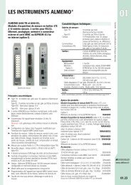
JC3000 FINGER OPERATED JOYSTICK CONTROLLER - Wimesure
JC3000 FINGER OPERATED JOYSTICK CONTROLLER - Wimesure
JC3000 FINGER OPERATED JOYSTICK CONTROLLER - Wimesure

You also want an ePaper? Increase the reach of your titles
YUMPU automatically turns print PDFs into web optimized ePapers that Google loves.
J C 3 0 0 0P E R F O R M A N C EM E C H A N I C A LLever breakout torque XY NmLever operating torque XY NmLever detent torque XY NmMaximum allowable torque XY NmLever operating angle °Lever actionLever gate profilesDetent angles °Maximum Z axis torqueExpected lifeWeightNmE N V I R O N M E N T A LOperating temperature ºCStorage temperature ºCEnvironmental protectionabove the flangeE L E C T R I C A LA n a l o g T r a c kResolutionTrack resistance (±20%) kΩTrack electrical angle °Output voltage range %Center tap voltage (no load) %Center tap angle °Supply voltage - maximum VdcOutput current – maximum mAWiper circuit impedance MΩInsulation resistanceS w i t c h - D i r e c t i o n a l o rCenter O f f / C e n t e r O n*Switch operating angle °Supply voltage - maximumLoad current - maximumD I M E N S I O N S A N DM O U N T I N G D E T A I L SgVdcmAJ OY S T I C K C O N T R O L L E RA N A LO G O U T P U T0.20.6 (full lever deflection at ±31°)0.1 approx.12.5 to 20 (full lever deflection, depending on gate and detent options selected)±31 max. in X and Y directions (Actual angle will depend on gate selected)Self centering, aligned X and YSingle axis in X or Y, square or plusNominal Lever angle Gate Code Track Code±5.5 - - -±12 - - -±18 ±19 ο 19 P_3±24 ±25 ο 25 P_4±30 ±31 ο 31 P_5where ο can be 1, S or P, & _ can be N, R, Q, E or L, see page 95>5 million operations205 nominal, without handle fitted-25 to +75-40 to +85IP66 (IP65 when ZC1 handle is fitted) IEC 60529(The joystick is unprotected below the flange)Virtually infinite1.8, 2, 2.9, 5 or 10±17, ±23 or ±28 (Depends on gate and track code selected)0-100, 10-90 or 25-75 of input (±2%)(Depends on analog potentiometer track selected see options page 9)48 - 52 of applied voltage±2.5325 †>1 † recommendedGreater than 50MΩ at 50Vdc3.75 either side of center position305* The <strong>JC3000</strong> has an additional center switch in each axis. When the handle is moved, the center switch signal will becomeopen circuit (‘break before make’) before the directional switch closes. This angle is typically less than 1º. The directional andcenter switches are provided to allow customers to integrate the joystick into their control system in a safe manner. Itis recommended that these switches are utilised to ensure a safe condition exists at all times.For dimensions, mounting details and installation recommendations see page 8.4† The long life resistive elements require a high impedance load in the wiper circuit to minimise the current flowing through the wiper for optimum conditions. Connecting the joystickoutput to a control circuit/controller with a Wiper Circuit Impedance that is lower than stated above can result in an offset of the output voltage through the travel of the joystick. Thismay be most noticeable when the joystick is at rest at the centre position. A lower than specified wiper circuit impedance can also result in a higher than stated output current and thisin turn will result in a reduced electrical life of the potentiometer element. The potentiometer element must be connected as a Voltage Divider and should not be used as a variableresistor. Use as a variable resistor will result in incorrect operation of the control system.<strong>Wimesure</strong> • 54, rue de Versailles • 78460 CHEVREUSE • Tél. 01 30 47 22 00 • Fax 01 30 47 28 29www.wimesure.fr • info@wimesure.fr
J C 3 0 0 0 J OY S T I C K C O N T R O L L E RA N A LO G O U T P U TE L E C T R I C A LC O N N E C T I O N SAll potentiometer track and directional/center/handle switch connections terminate in a 12-wayHirose DF3-12P-2DS(01) series connector on each joystick axis – a mating connector and flylead isavailable (one is required for each axis). The connectors used on the <strong>JC3000</strong> joystick are goldplated, therefore the mating connectors should also be gold plated.Mating 12-way connectorand flyleadsSA310621 MK1 – Connector, terminals and 100mm long UL1007 wires – 28AWG (7/0.127mm)SA310621 MK2 – Connector, terminals and 300mm long UL1007 wires – 28AWG (7/0.127mm)Y-Axis Allocation X-Axis Allocation Connector 12-way HarnessPin NumberOutput voltage signal Output voltage signal 1 BlackSwitch track N/O (lever forward +Y) Switch track N/O (lever right +X) 2 RedNot connected Normally not connected unless ZC1/ZCS 3 Bluehandle is fitted (XN code only)Potentiometer center tap Potentiometer center tap 4 WhiteSwitch track center on Switch track center on 5 GreenNot connected Normally not connected unless ZC1/ZCS 6 Yellowhandle is fitted (XN code only)Switch track N/O (lever backward -Y) Switch track N/O (lever left –X) 7 BrownWire ColourSwitch track common Switch track common 8 OrangeNormally not connected unless ZC1/ZCS Not connected 9 Greyhandle is fitted (NY and XY code only)Potentiometer backward (-V or zero supply) Potentiometer left (-V or zero supply) 10 VioletPotentiometer forward (+V supply) Potentiometer right (+V supply) 11 Black/WhiteNormally not connected unless ZC1/ZCS Not connected 12 Black/Redhandle is fitted (NY and XY code only)M U L T I P I N C O N N E C T O RD I A G R A MPin 12Pin 1A N A L O G T R A C KD I A G R A MY-AXISX-AXISTo handleTo handleTo handleTo handleExtremeLeftDirectionalswitchExtremeRightTo handleTo handleCentertapExtremeFwdPotWiperoutput12 way Hirose connectorPotDirectionalswitchExtremeBackCentertapDenotes wiper contact12 way Hirose connectorWiperoutputSee pin out allocation in Electrical Connections above.To handleTo handle<strong>Wimesure</strong> • 54, rue de Versailles • 78460 CHEVREUSE • Tél. 01 30 47 22 00 • Fax 01 30 47 28 29www.wimesure.fr • info@wimesure.fr5
J C 3 0 0 0J OY S T I C K C O N T R O L L E RS W I TC H E D O U T P U TP E R F O R M A N C EM E C H A N I C A LLever breakout torque XY NmLever operating torque XY NmLever detent torque XY NmMaximum allowable torque XY NmLever operating angle ºLever actionLever gate profilesDetent angles ºMaximum Z axis torqueExpected lifeWeightNmg0.20.6 (full lever deflection at ±31°)0.1 approx.12.5 to 20 (full lever deflection, depending on gate and detent options selected)±31 max. in X and Y directions (Actual angle will depend on gate selected)Self centering, aligned X and YSingle axis in X or Y, Square or PlusNominal Lever angle Gate Code Track Code±5.5 - - -±12 - - -±18 ±19 ο 19 SW3±24 ±25 ο 25 SW4±30 ±31 ο 31 SW5where ο can be 1, S or P, see page 95>5 million operations205 nominal, without handle fittedE N V I R O N M E N T A LOperating temperature ºCStorage temperature ºCEnvironmental protectionabove the flange-25 to +75-40 to +85IP66 (IP65 when ZC1 handle is fitted) IEC 60529(The joystick is unprotected below the flange)E L E C T R I C A LSwitch TrackNumber of switch positionsNumber of detentsSwitch angles °Supply voltage - maximum VdcLoad current – maximum mAInsulation resistance3, 4 or 5 either side of center3, 4 or 5 either side of center (Also option for no detents)(SW1) ±4, (SW2)±10, (SW3)±16, (SW4)±22, (SW5)±28325Greater than 50MΩ at 50VdcS w i t c h -Center OffSwitch operating angle °Supply voltage - maximum VdcLoad current - maximum mA2.5 either side of center position305S W I T C H A C T I V A T I O ND I A G R A MSwitch track output and centerswitch signals on both X and Yaxes are Normally Open atlever center position. Switchsequences close depending onthe direction of levermovement and the detentposition.See the diagram for the switchactivation profile.Positional switches Center switchSwitch 1(Pin 3)Switch 1(Pin 4)Switch 2Switch 3Switch 4OpenClosedOpenClosedOpenClosedOpenClosedOpenClosedOpenClosedBack / LeftBack / Left2.5º22º16º10º4º2.5ºFWD / RightFWD / Right4º10º16º22ºSwitch 5OpenClosed28º28º6<strong>Wimesure</strong> • 54, rue de Versailles • 78460 CHEVREUSE • Tél. 01 30 47 22 00 • Fax 01 30 47 28 29www.wimesure.fr • info@wimesure.fr
J C 3 0 0 0 J OY S T I C K C O N T R O L L E RS W I TC H E D O U T P U TE L E C T R I C A LC O N N E C T I O N SAll switch track/center/handle switch connections terminate in a 12-way Hirose DF3-12P-2DS(01)series connector on each joystick axis – a mating connector & flylead is available (one is required foreach axis). The connectors used on the <strong>JC3000</strong> joystick are gold plated, therefore the matingconnectors should also be gold plated.Mating 12-way connectorand flyleadsSA310621 MK1 – Connector, terminals and 100mm long UL1007 wires – 28AWG (7/0.127mm)SA310621 MK2 – Connector, terminals and 300mm long UL1007 wires – 28AWG (7/0.127mm)Y-Axis Allocation X-Axis Allocation Connector 12-way HarnessPin NumberSwitch track common Switch track common 1 BlackCenter off switch Center off switch 2 RedSwitch 1 (lever forward +Y) Switch 1 (lever right +X) 3 BlueSwitch 1 (lever backward -Y) Switch 1 (lever left -X) 4 WhiteSwitch 2 (forward & backward) Switch 2 (right & left) 5 GreenSwitch 3 (forward & backward) Switch 3 (right & left) 6 YellowSwitch 4 (forward & backward) Switch 4 (right & left) 7 BrownWire ColourSwitch 5 (forward & backward) Switch 5 (right & left) 8 OrangeNot connected Not connected 9 GreyNormally not connected unless ZC1/ZCS Normally not connected unless ZC1/ZCS 10 Violethandle is fitted (NY and XY code only) handle is fitted (XN code only)Normally not connected unless ZC1/ZCS Normally not connected unless ZC1/ZCS 11 Black/Whitehandle is fitted (NY and XY code only) handle is fitted (XN code only)Switch track common Switch track common 12 Black/RedM U L T I P I N C O N N E C T O RD I A G R A MPin 12 Pin 1S W I T C H T R A C KD I A G R A MY-AXISTo handleTo handleTo handleExtremeLeftX-AXISExtremeRightCenter switch12 way Highrose connectorPositional switchesCenter switchExtremeFwdTo handlePositional switches12 way Highrose connectorTo handleExtremeBackTo handleDenotes wiper contactSee pin out allocation in Electrical Connections above<strong>Wimesure</strong> • 54, rue de Versailles • 78460 CHEVREUSE • Tél. 01 30 47 22 00 • Fax 01 30 47 28 29www.wimesure.fr • info@wimesure.fr7
J C 3 0 0 0J OY S T I C K C O N T R O L L E RD I M E N S I O N SNote: drawings not to scaleMountingdetail40.00 ±0.05Holes tosuit M3screwsForwardorientationfeature oncasting55.00 ±0.075FWD (Y axis)40.00 ±0.05ø 51.0050.7555.00 ±0.075Left(X axis)Right(X axis)Lever angle (Xº) depends on gateselected.Xº XºHLO handle shown(see page 10 for alternatives)Back (Y axis)ø32.005.0 nominal(mounting flange to pivot)ø 50.50 ±0.2559.2 max98.25 maxI N S T A L L A T I O NThe joystick is designed to be fitted from below the mounting panel, through a 50.75/51.00mmdiameter hole. The effectiveness of the joystick flange sealing is dependent on the panel mountingsurface being sufficiently rigid to compress the sealing gaiter. The surface finish of the mountingpanel is critical to achieving an adequate seal and rough surface finishes, paint chips, deepscratches, etc. should be avoided.Recommended panel thickness3.5 to 6mmRecommended screw torqueThe <strong>JC3000</strong> joystick requires 4 x M3 screws (not supplied) to attach the flange to the mountingpanel. To maintain an effective seal between the joystick flange and the mounting panel, themounting screws should be tightened to a recommended fixing torque of 1Nm.8<strong>Wimesure</strong> • 54, rue de Versailles • 78460 CHEVREUSE • Tél. 01 30 47 22 00 • Fax 01 30 47 28 29www.wimesure.fr • info@wimesure.fr
J C 3 0 0 0J OY S T I C K C O N T R O L L E RH O W TO S P E C I F YPERFORMANCE OPTIONS FEATURE CODEA X E SSingle axis in Y direction only - Forward/BackwardSingle axis in X direction only - Right/LeftDual axisNYXNXYG A T ESelecting the gate styleand angle determines the trackcode for switched output and 2/3of the final track code for analogoutput versions.Single axis with ±31º lever range (Track code = P–5 or SW5) 131Single axis with ±25º lever range (Track code = P–4 or SW4) 125Single axis with ±19º lever range (Track code = P–3 or SW3) 119Square with ±31º lever range in X and Y (Track code = P–5 or SW5) S31Square with ±25º lever range in X and Y (Track code = P–4 or SW4) S25Square with ±19º lever range in X and Y (Track code = P–3 or SW3) S19Plus with ±31º lever range (Track code = P–5 or SW5) P31Plus with ±25º lever range (Track code = P–4 or SW4) P25Plus axis with ±19º lever range (Track code = P–3 or SW3) P19T R A C K S -Analog outputFinal track code element * isdetermined by the gate/anglepreviously selected.Analog potentiometer - 1.8k 0-100% ±3.75º directional switchPN*Analog potentiometer - 2k 10-90% ±3.75º directional switch PR*Analog potentiometer - 2.9k 25-75% ±3.75º directional switchPQ*Analog potentiometer - 5k 0-100% ±3.75º directional switch PE*Analog potentiometer - 10k 0-100% ±3.75º directional switch PL*T R A C K S -Switched outputSwitched track - 5 switches either side of centerSwitched track - 4 switches either side of centerSwitched track - 3 switches either side of centerSW5SW4SW3L E V E R S P R I N G F O R C EMedium duty 0.2Nm breakout, 0.6Nm full deflectionMS E A TAligned with axisAD E T E N T SNo detent feature - available for all gate code optionsD005 each side of center position - option for gate codes 131; S31; P31 D5H4 each side of center position - option for gate codes 125; S25; P25 D4H3 each side of center position - option for gate codes 119; S19; P19 D3HI N T E R F A C EStandard interface - no electronicsSTNH A N D L E S T Y L ESee pages 10-11No handle, plain leverNo handle, M5 threaded leverTapered handle, no functionsBall handle, no functionsLow profile, fluted handle, no functionsHandle with momentary push buttonHandle with momentary switch actionNHPNHTK10B00HL0ZC1ZCSEXAMPLE ORDER CODES<strong>JC3000</strong>-XY- S31-PN5-M-A-D00- STN-K10<strong>JC3000</strong>-NY-131- SW5-M-A-D5H- STN-ZC1<strong>Wimesure</strong> • 54, rue de Versailles • 78460 CHEVREUSE • Tél. 01 30 47 22 00 • Fax 01 30 47 28 29www.wimesure.fr • info@wimesure.fr9
J C 3 0 0 0J OY S T I C K C O N T R O L L E RH A N D L E O P T I O N SNHPNo handle, plain leverNHTNo handle, M5 threaded leverø6.35 ±0.00617.2 ±0.5M5 thread59.36 max5.55 ±0.151.95 maxNHPNHTK10This handle option is a simple taperedstyle with no switch functions, allowingsimple fingertip control.ø18.0ø31.95B00This handle option is a spherical ball stylewith no switch functions, allowing simple‘finger and thumb’ control The handlehas a recessed diametral groove on thecircumference to aid grip.67.80 max72.90 maxK10B00HL0This handle option is a low profile, flutedstyle that has a maximum 59.2mm heightabove the mounting panel. This optionallows closer spacing of multiple joystickswithin a small surface area - typically inapplications like remote control chestpacks and robotics equipment.59.20 maxø32.00HL010<strong>Wimesure</strong> • 54, rue de Versailles • 78460 CHEVREUSE • Tél. 01 30 47 22 00 • Fax 01 30 47 28 29www.wimesure.fr • info@wimesure.fr
ZC1 or ZCS HANDLE OPTIONA switch function can be incorporated byusing the ZC1 external button switch orthe ZCS internal switch to verify thechange in signals from the joystick.External switchø26,1ø23.00Press toactivateswitch73.80 max76.00 maxZC1ZCSPERFORMANCE ZC1 ZCSMaximum height above flange mm 73.8 76Maximum diameter mm 26.1 23Environmental sealing (IEC 60529) IP65 IP66Number of switches 1 1Action Momentary button Momentaryhandle depressSwitch operating force N 3 7Maximum current mA 200 @ 50Vdc 100 @ 30VdcExpected electrical life operations 1 million 500,000ZC1 or ZCS ELECTRICALCONNECTIONSSwitch connections terminate on the Hirose DF3 series connector. Actual pin allocation dependson the joystick track type and gate selection.See page 5 for Analog Output version connections.See page 7 for Switched Output version connections.11<strong>Wimesure</strong> • 54, rue de Versailles • 78460 CHEVREUSE • Tél. 01 30 47 22 00 • Fax 01 30 47 28 29www.wimesure.fr • info@wimesure.fr