
You also want an ePaper? Increase the reach of your titles
YUMPU automatically turns print PDFs into web optimized ePapers that Google loves.
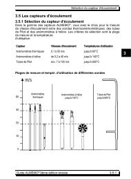
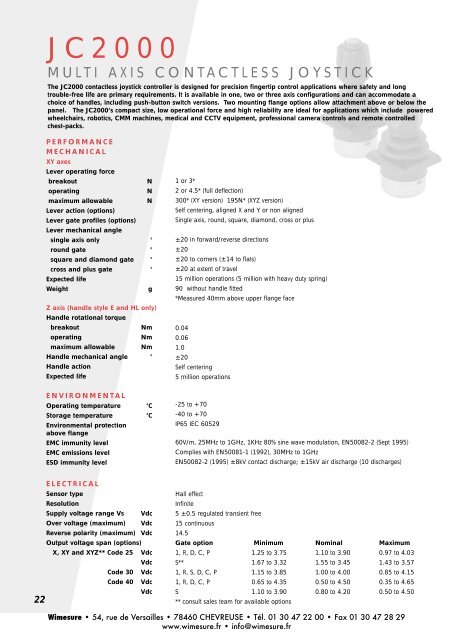
J C 2 0 0 0M U L T I A X I S C O N T A C T L E S S J O Y S T I C KThe <strong>JC2000</strong> contactless joystick controller is designed for precision fingertip control applications where safety and longtrouble-free life are primary requirements. It is available in one, two or three axis configurations and can accommodate achoice of handles, including push-button switch versions. Two mounting flange options allow attachment above or below thepanel. The <strong>JC2000</strong>’s compact size, low operational force and high reliability are ideal for applications which include poweredwheelchairs, robotics, CMM machines, medical and CCTV equipment, professional camera controls and remote controlledchest-packs.P E R F O R M A N C EM E C H A N I C A LXY axesLever operating forcebreakoutNoperatingNmaximum allowableNLever action (options)Lever gate profiles (options)Lever mechanical anglesingle axis only °round gate °square and diamond gate °cross and plus gate °Expected lifeWeightgZ axis (handle style E and HL only)Handle rotational torquebreakoutNmoperatingNmmaximum allowable NmHandle mechanical angle °Handle actionExpected lifeE N V I R O N M E N T A LOperating temperature °CStorage temperature °CEnvironmental protectionabove flangeEMC immunity levelEMC emissions levelESD immunity level1 or 3*2 or 4.5* (full deflection)300* (XY version) 195N* (XYZ version)Self centering, aligned X and Y or non alignedSingle axis, round, square, diamond, cross or plus±20 in forward/reverse directions±20±20 to corners (±14 to flats)±20 at extent of travel15 million operations (5 million with heavy duty spring)90 without handle fitted*Measured 40mm above upper flange face0.040.061.0±20Self centering5 million operations-25 to +70-40 to +70IP65 IEC 6052960V/m, 25MHz to 1GHz, 1KHz 80% sine wave modulation, EN50082-2 (Sept 1995)Complies with EN50081-1 (1992), 30MHz to 1GHzEN50082-2 (1995) ±8kV contact discharge; ±15kV air discharge (10 discharges)E L E C T R I C A LSensor typeResolutionSupply voltage range Vs VdcOver voltage (maximum) VdcReverse polarity (maximum) VdcOutput voltage span (options)X, XY and XYZ** Code 25 VdcVdcCode 30 VdcCode 40 Vdc22VdcHall effectInfinite5 ±0.5 regulated transient free15 continuous14.5Gate option Minimum Nominal Maximum1, R, D, C, P 1.25 to 3.75 1.10 to 3.90 0.97 to 4.03S** 1.67 to 3.32 1.55 to 3.45 1.43 to 3.571, R, S, D, C, P 1.15 to 3.85 1.00 to 4.00 0.85 to 4.151, R, D, C, P 0.65 to 4.35 0.50 to 4.50 0.35 to 4.65S 1.10 to 3.90 0.80 to 4.20 0.50 to 4.50** consult sales team for available options<strong>Wimesure</strong> • 54, rue de Versailles • 78460 CHEVREUSE • Tél. 01 30 47 22 00 • Fax 01 30 47 28 29www.wimesure.fr • info@wimesure.fr
Output impedanceΩCenter reference output (no load) %Center reference impedance kΩCurrent consumption - max mAReturn to center voltage-no load mVOutput ramp100 each axis49 - 51 of supply voltage Vs1.124X and Y axis Within ±60 of Vs/2 @ 20°C (±73 over full temperature range)XY with gate S Within ±113 of Vs/2 @ 20°C (±126 over full temperature range)Z axis Within ±100 of Vs/2 @ 20°C (±113 over full temperature range)XY axes The dual outputs of the XY axes can be independently selected to berising together in the same direction (PP) or opposed (PN). See order codeXYZThe three axis version can only provide a single output per axisD I M E N S I O N STop flange optionK1 standard handleX and XY onlyS handleX and XY onlyS1-S5 handleX and XY onlyB0 handleX and XY only64Gaiter protectorsupplied on K1 andBO only(optional fit)717869FORWARD6.331Panel mounting detail35ø3.5 in fourplaces47.5E1-E5 handleE handleX, XY and XYZ versionsX, XY and XYZ versions HL handleX, XY and XYZ versionsø A7835Top panel mounting A = 42Under panel mounting A = 31.57157ReverseRightXYXLeftOrientationident47.5YForwardFlange dimension 44.3mm square (with trim plate removed)4 off through holes ø3.3mm, countersunk on top surface.Use M3 x 90ºcsk screws for mounting.D I M E N S I O N SMid flange optionX and XY axes only44.3RightReverseYX XYLeft35OrientationidentPanel mounting detail35Forwardø3.5 in fourplaces44.3ø31.535B0 handleshown75*GaitortrappedbeneathpanelFour off bosses tosuit fixing screwø41431.58.89Boss* This dimension is 6mm greater than thehandle heights shown for the top flange optionSpecification continued overleaf ☛23<strong>Wimesure</strong> • 54, rue de Versailles • 78460 CHEVREUSE • Tél. 01 30 47 22 00 • Fax 01 30 47 28 29www.wimesure.fr • info@wimesure.fr
O U T P U T T R A C K I N GOutput shown for samedirection - PP or NNOutput difference between sensor 1 & sensor 2 (same axis)with Vs = 5VReverseLeftForwardRight5.6%1.7%01.7%5.6%46%46%54%54%End stop50% travelEnd stopE L E C T R I C A LC O N N E C T I O N SMating Connector8 Pin FCI Minitek TM 89361-708 IDC Connector (order separately as P302137)or supplied with 0.5m ribbon cable fitted (order as P302138)13572468Pin NumberDescriptionXY JoystickXYZ Joystick1 Positive voltage supply Positive voltage supply2 Left/Right output 1 Left/Right output3 Zero voltage supply Zero voltage supply4 Forward/Reverse output 1 Forward/Reverse output5 Forward/Reverse output 2 NC6 Center tap Center tap7 Left/Right output 2 Z Axis output8 Switch output (NC if no switch) Switch output (NC if no switch)Switch is connected between pin 1 and 824<strong>Wimesure</strong> • 54, rue de Versailles • 78460 CHEVREUSE • Tél. 01 30 47 22 00 • Fax 01 30 47 28 29www.wimesure.fr • info@wimesure.fr
J C 2 0 0 0M U L T I A X I S C O N T A C T L E S S J O Y S T I C KH O W T O S P E C I F YPERFORMANCE OPTIONS FEATURE CODE FEATURE AVAILABILITYX XY XYZM O U N T I N G F L A N G E Top flange <strong>JC2000</strong>-T ✓ ✓ ✓Mid flange (not available with XYZ) <strong>JC2000</strong>-M ✓ ✓A X E SO U T P U T R A M PO U T P U T S PA NH A N D L E S T Y L E SSee page 23GATE(lever movement limiter)S E A TL E V E R S P R I N G F O R C ESingle axis X ✓Dual axis XY ✓Three axis (only available with top flange) XYZ ✓dual output - same ramp PPOOO ✓dual output - opposite ramp PNOOO ✓dual output - same ramp each axis PPPPO ✓dual output - same ramp X, opposite ramp Y PPNNO ✓dual output - opposite ramp each axis PNPNO ✓single output - same ramp each axis POPOP ✓single output - same ramp X and Z, opposite ramp Y PONOP ✓single output - same ramp Y and Z, opposite ramp X PONON ✓single output - opposite ramp each axis NONON ✓1.1 to 3.9 Vdc nominal 25 ✓ ✓ ✓1.0 to 4.0 Vdc nominal 30 ✓ ✓ ✓*0.5 to 4.5 Vdc nominal 40 ✓ ✓ ✓*Standard tapered handle K1 ✓ ✓Ball handle B0 ✓ ✓Short ergonomic handle HL ✓ ✓ ✓Ergonomic handle E ✓ ✓ ✓Ergonomic with Black push button E1 ✓ ✓ ✓Ergonomic with Red push button E2 ✓ ✓ ✓Ergonomic with Green push button E3 ✓ ✓ ✓Ergonomic with Yellow push button E4 ✓ ✓ ✓Ergonomic with Blue push button E5 ✓ ✓ ✓Straight handle S ✓ ✓Straight with Black push button S1 ✓ ✓Straight with Red push button S2 ✓ ✓Straight with Green push button S3 ✓ ✓Straight with Yellow push button S4 ✓ ✓Straight with Blue push button S5 ✓ ✓Single axis 1 ✓Round R ✓ ✓Square* S ✓ ✓Diamond D ✓ ✓Cross X C ✓ ✓Plus + P ✓ ✓Aligned with axis P ✓ ✓Non-aligned N ✓ ✓ ✓Standard duty, 1N breakout, 2N full deflection S ✓ ✓ ✓Heavy duty, 3N breakout, 4.5N full deflection H ✓ ✓ ✓E X A M P L E O R D E R C O D EJ C 2 0 0 0 -T- X Y- P P P P O - 4 0 - E 5 - R - P - HTwo axis version with all outputs same sense, 40% output span,ergonomic handle style withBlue push button switch, round gate and aligned seat, with heavy spring.*Consult the sales team for available output span options, when selecting XYZwith S gate option.25<strong>Wimesure</strong> • 54, rue de Versailles • 78460 CHEVREUSE • Tél. 01 30 47 22 00 • Fax 01 30 47 28 29www.wimesure.fr • info@wimesure.fr
GENERAL NOTES ON FINGER OPERATED JOYSTICKSM E C H A N I C A L L O A D SPenny+Giles joystick controllers are robust and designed to suit typical applications. System designers should ensure that thejoystick is not positioned where it could be subjected to excessive loads greater than the maximum allowable load stated in theproduct specification.M O D I F I C A T I O N A N D U S A G EAny modification of a joystick by the user is strongly discouraged and will invalidate the warranty and Penny+Giles liability.The handles supplied with the finger operated controllers are intended for fingertip and not full hand operation. Handlesmust not be replaced with a taller handle otherwise the increased load applied to the joystick may result in permanentdamage.U S E R M A I N T E N A N C E / A D J U S T M E N TAll joysticks are supplied by Penny+Giles fully adjusted and ready for installation. There are no user adjustable ormaintainable parts within the joysticks. Any attempt to dismantle the joystick will invalidate the warranty and may leave thesystem into which the joystick is installed in a dangerous condition.S A F E T YFor a system to operate safely it must be able to differentiate between commanded and uncommanded inputs. Systemdesigners should take steps to detect and manage joystick and system failures that may give rise to an erroneous output. Forsafety critical functions we recommend that an independent momentary action ‘system enable’ switch is used. This switch canbe incorporated into the joystick as a ‘Person Present’ switch or can be a separate foot or hand operated momentary switch.All functions controlled by the joystick should be disabled when this switch is released. The control system should look for theappropriate ‘system enable’ switch output before the joystick is displaced from the neutral position. Functions controlled by thejoystick should not be enabled until this is the case.J O Y S T I C K I N T E G R I T Y C H E C K O N P O W E R U POn system power-up, the system should check that all joystick outputs are in neutral and safety critical functions controlled bythe joystick should not be enabled until this is the case.L I F EPenny+Giles joysticks are designed and tested to provide a working life that is acceptable for the majority of applications.System designers should be satisfied that the life stated in the joystick specification is sufficient for the intended application.J C 2 0 0 0INSTALLATION AND APPLICATION NOTES26S E A L I N G T H E J O Y S T I C K T O T H E P A N E LSee panel mounting detail on page 23 for recommended machining detail to accept the <strong>JC2000</strong>. Prior to installation checkthat the gate (lever movement limiter) positioned under the gaiter at the top of the joystick is correctly located and orientated.The joystick is sealed above the mounting surface to prevent dust and water ingress to IP65 and is supplied with mountinghardware (sealing gasket and trim plate) suitable for mounting from above the panel face. The effectiveness of the seal isdependent on the mounting surface being sufficiently rigid to compress the sealing gasket. The finish of the mounting surfaceis critical to achieving an adequate seal and rough surface finishes, paint chips, deep scratches etc. should be avoided. Thejoystick should not be used if the flexible rubber gaiter becomes perforated.Below the mounting surface the joystick should be allowed to breathe freely but be protected from excessive dust and directwater spray. Where the joystick is mounted in a control box, the box should be allowed to breathe at its lowest point. If the boxis subjected to water spray it may be necessary to provide a waterproof breather at the lowest point.It is possible to mount the <strong>JC2000</strong> from under the panel surface by discarding the trim plate and sealing gasket andcompressing the base of the flexible gaiter against the panel and mounting flange. This reduces the lever height above thepanel, but increases the space required to accommodate the joystick body below the panel. See panel mounting detail onpage 23 for dimensions.<strong>Wimesure</strong> • 54, rue de Versailles • 78460 CHEVREUSE • Tél. 01 30 47 22 00 • Fax 01 30 47 28 29www.wimesure.fr • info@wimesure.fr
D U A L O U T P U T S - X A N D X Y V E R S I O N S O N L YEach <strong>JC2000</strong> joystick axis is equipped with two outputs and it is recommended that both outputs are continuously comparedto ensure that the difference does not exceed the maximum specified difference plus a suitable ‘safety margin’. In addition,machine movement should not be enabled until both outputs from any one axis exceed the centre threshold voltage plus asuitable ‘safety margin’. (e.g. 2 x joystick centre tolerance)The outputs in normal use are within the maximum span limits shown on page 22. Any output significantly outside of thisrange must be regarded as erroneous and appropriate safe action taken. A high value pull-up or pull-down resistance shouldbe added to the X and Y outputs such that in the unlikely event of a wire or connector failure the output will be pulled out ofrange.D U A L O U T P U T S E N S E ( D I R E C T I O N )Dual outputs from any <strong>JC2000</strong> joystick axis can be configured during manufacture in one of two possible ways. These aredesignated within the joystick specification as same-ramp (P) or opposite-ramp (N). The diagrams, below, show dual outputs;for single output or a Z axis either output 1 or 2 can be chosen.The ramps at their lower end start at 25%, 20% or 10% of supplyvoltage and at their upper end finish at 75%, 80% or 90% of supplyvoltage, depending on output option.In the same-ramp configuration the outputs of an axis can be directlycompared to determine the serviceability of the joystick.Output 1Output 2Max. difference sum tosupply voltageOutput 2Sum of outputs1 & 2SupplyVoltageIn the opposite-ramp configuration the sum of the outputs from anyaxis should within limits, equal the applied voltage.Max. differencebetween output 1 & 2Same RampOutput 1Opposite RampC E N T E R T A PA center tapping is provided as a means of verifying the integrity of the supply voltage at the joystick. Clearly a highresistance or open circuit in either the +ve supply or 0V connections will affect the joystick outputs. The normal output at thecenter tap connection is 49% to 51% of the supply voltage. A center tap output outside this range indicates a fault in thesupply to the joystick.S I N G L E O U T P U T S - X Y Z O N L YWhere a <strong>JC2000</strong> joystick incorporating only a single sensor per axis is used to control safety critical functions an independentmomentary action system enable switch must be provided.O U T P U T I M P E D A N C EThe outputs at the center position and the end of travel are specified with an infinite load impedance or zero current. Theeffect of adding a finite load impedance will be to source or sink current through the joystick output impedance. The voltagedropped through the joystick output impedance must be taken into account when the system threshold voltages are beingdefined. The impedance of the <strong>JC2000</strong> outputs are specified on page 23.O U T P U T N O I S EThe <strong>JC2000</strong> incorporates Hall effect sensors to detect the position of each of the joystick axes. A side effect of the use of thesesensors is electrical noise superimposed on the output, typically of the order of 20mV peak to peak. This noise can be simplyfiltered out by the user.M A G N E T I C I M M U N I T YMagnetic screening minimises the sensitivity to external magnetic fields. However the use of the joystick in close proximity tosources of high magnetic fields is not recommended.A P P L I E D V O L T A G E SThe <strong>JC2000</strong> is designed to operate from a regulated 5Vdc ±0.5V supply, free from voltage transients. Under nocircumstances should voltages above 5.5V be applied to the joystick. The outputs from the <strong>JC2000</strong> are ratiometric and aredependent on the input voltage.<strong>Wimesure</strong> • 54, rue de Versailles • 78460 CHEVREUSE • Tél. 01 30 47 22 00 • Fax 01 30 47 28 29www.wimesure.fr • info@wimesure.fr27