RouterBOARD 751 series
RouterBOARD 751 series
RouterBOARD 751 series

You also want an ePaper? Increase the reach of your titles
YUMPU automatically turns print PDFs into web optimized ePapers that Google loves.
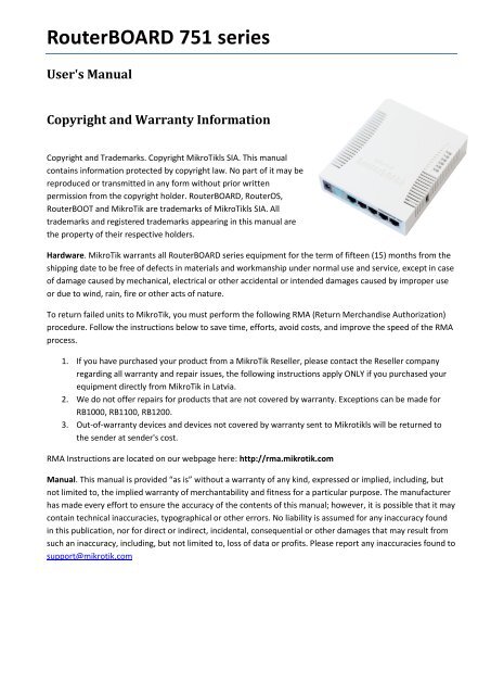
<strong>RouterBOARD</strong> <strong>751</strong> <strong>series</strong>User's ManualCopyright and Warranty InformationCopyright and Trademarks. Copyright MikroTikls SIA. This manualcontains information protected by copyright law. No part of it may bereproduced or transmitted in any form without prior writtenpermission from the copyright holder. <strong>RouterBOARD</strong>, RouterOS,RouterBOOT and MikroTik are trademarks of MikroTikls SIA. Alltrademarks and registered trademarks appearing in this manual arethe property of their respective holders.Hardware. MikroTik warrants all <strong>RouterBOARD</strong> <strong>series</strong> equipment for the term of fifteen (15) months from theshipping date to be free of defects in materials and workmanship under normal use and service, except in caseof damage caused by mechanical, electrical or other accidental or intended damages caused by improper useor due to wind, rain, fire or other acts of nature.To return failed units to MikroTik, you must perform the following RMA (Return Merchandise Authorization)procedure. Follow the instructions below to save time, efforts, avoid costs, and improve the speed of the RMAprocess.1. If you have purchased your product from a MikroTik Reseller, please contact the Reseller companyregarding all warranty and repair issues, the following instructions apply ONLY if you purchased yourequipment directly from MikroTik in Latvia.2. We do not offer repairs for products that are not covered by warranty. Exceptions can be made forRB1000, RB1100, RB1200.3. Out-of-warranty devices and devices not covered by warranty sent to Mikrotikls will be returned tothe sender at sender's cost.RMA Instructions are located on our webpage here: http://rma.mikrotik.comManual. This manual is provided “as is” without a warranty of any kind, expressed or implied, including, butnot limited to, the implied warranty of merchantability and fitness for a particular purpose. The manufacturerhas made every effort to ensure the accuracy of the contents of this manual; however, it is possible that it maycontain technical inaccuracies, typographical or other errors. No liability is assumed for any inaccuracy foundin this publication, nor for direct or indirect, incidental, consequential or other damages that may result fromsuch an inaccuracy, including, but not limited to, loss of data or profits. Please report any inaccuracies found tosupport@mikrotik.com
USER'S MANUAL ............................................................................................................................................................... 1COPYRIGHT AND WARRANTY INFORMATION ................................................................................................................... 1SYSTEM BOARD VIEW AND LAYOUT ................................................................................................................................. 3SPECIFICATIONS ................................................................................................................................................................ 3HARDWARE GUIDE ........................................................................................................................................................... 4MEMORY AND STORAGE DEVICES ................................................................................................................................................. 4Memory ............................................................................................................................................................................ 4Storage Device ................................................................................................................................................................. 4INPUT/OUTPUT PORTS ............................................................................................................................................................... 4Ethernet ports .................................................................................................................................................................. 4LEDS ...................................................................................................................................................................................... 4USER'S GUIDE ................................................................................................................................................................... 4POWERING ............................................................................................................................................................................... 4BOOTING OPTIONS .................................................................................................................................................................... 5Onboard NAND Storage Device ........................................................................................................................................ 5Booting from network ...................................................................................................................................................... 5Operating System Support ............................................................................................................................................... 5BUTTONS AND JUMPERS ............................................................................................................................................................. 6WIRELESS DEVICE ...................................................................................................................................................................... 6ROUTERBOOT ................................................................................................................................................................... 6BOOT LOADER CONFIGURATION ................................................................................................................................................... 6BOOT LOADER UPGRADING ......................................................................................................................................................... 6PRIMARY BOOT LOADER ............................................................................................................................................................. 6ROUTEROS FUNCTIONS .................................................................................................................................................... 7FIRMWARE INFORMATION ........................................................................................................................................................... 7FIRMWARE SETTINGS ................................................................................................................................................................. 7APPENDIX ......................................................................................................................................................................... 7CONNECTOR INDEX .................................................................................................................................................................... 7BUTTON INDEX ......................................................................................................................................................................... 8ETHERNET CABLES ..................................................................................................................................................................... 82
System Board View and Layout<strong>RouterBOARD</strong> <strong>751</strong> Series User's ManualYou can download the board dimensions and case design files (PDF and DXF) from www.routerboard.comSpecifications<strong>RouterBOARD</strong> <strong>751</strong>U-2HnD / <strong>RouterBOARD</strong> <strong>751</strong>G-2HnDCPUMemoryBoot loaderData storageEthernetAR7241 400MHz32MB DDR SDRAM onboardRouterBOOT64MB onboard NAND memory chipRB<strong>751</strong>U-2HnD: Five 10/100 Mbit/s Ethernet ports supporting Auto-MDI/XRB<strong>751</strong>G-2HnD: Five 10/100/1000 Gigabit ports with Auto-MDI/XMiniPCI slot -ExpansionUSB 2.0 portCompactFlash slots -Serial port -LEDsPower, NAND activity, 5 Ethernet and 1 wireless LEDsBeeper +Power at the devicePower over EthernetPower consumptionDimensionsTemperatureHumidityDC power jack (5.5mm outside and 2mm inside diameter, female, pin positive plug) accepts 8-30V DCEther 1 requires 8-30V DC (non 802.3af), to compensate for losses, it’s recommended to use 12V or moreUp to 7W113x138x29mm. Weight without packaging and cables: 230gIndoor device. Operational temperature: -20°C to +50°COperational: up to 70% relative humidity (non-condensing)3
RouterOSRouterOS v5, Level4 licenseWireless specificationsWirelessAntennaRX SensitivityIntegrated Wireless 2.4GHz 802.11b/g/n 2x2 MIMO2x2 MIMO PIF antennas, max gain 2.5dBi, external MMCX option802.11g: -96dBm (6Mbit/s) to -81dBm (54Mbit/s)802.11n: –96 dBm (MCS0) to –78 dBm (MCS7)TX Power802.11g: 30dBm (6Mbps) to 27dBm (54Mbps)802.11n: 30dBm (MCS0) to 26dBm (MCS7)ModulationsOFDM: BPSK, QPSK, 16 QAM, 64QAM; DSSS: DBPSK, DQPSK, CCKHardware GuideMemory and Storage DevicesMemoryThe RB<strong>751</strong> has 32MB of built-in memory. There are no memory upgrade options.Storage DeviceThe device is equipped with one built in NAND nonvolatile memory chip.Input/Output PortsEthernet portsThere are five individual Ethernet ports. Ports 2-5 are connected to a switch and can be switched together byan option in the RouterOS software.All cables made to EIA/TIA 568A/B cable specifications will work correctly (see Connector Index for pinout).Note that this port supports automatic cross/straight cable correction (Auto MDI/X), so you can use eitherstraight or cross-over cable for connecting to other network devices.LEDsEthernet LED lights up when a cable is connected, these LEDs don’t show ethernet activity, just connectivity.Wireless LED flashes on activity. Power LED indicates that the device receives power. ACT LED shows NANDactivity and can be programmed to show other things via RouterOS LED menu.User's GuidePoweringThe device accepts powering from the power jack or from the first Ethernet port (Passive PoE):DC power jack (5.5mm outside and 2mm inside diameter, female, pin positive plug) accepts 8-30V DCThe first Ethernet port accepts passive Power over Ethernet accepts 8-30V DCUnder maximum load, the power consumption of this device is 7W4
<strong>RouterBOARD</strong> <strong>751</strong> Series User's ManualBooting optionsRouterOS is the operating system of all <strong>RouterBOARD</strong> routers. Please see detailed configuration guide herehttp://wiki.mikrotik.com/wiki/Category:ManualInitial configuration includes the following:wirelesss AP with SSID „MikroTik” has been enabled, and bridged to ports Ether2-Ether5. This bridgehas a DHCP server runni ng, so you can connect to the devide using the Web based „Webfig” interfacefrom Ether2-Ether5 or from the wireless interface. Open http://192.168.88.1 in your browser, in thepage that opens, select „Webfig” and log in with username „admin” and no password. The Ether1 porthas a firewall on it, and a DHCP client, so it’s configured to be connected to your ISP.An alternative configuration option is the MikroTik Winbox utility (Windows only). Winbox can be used toconnect to the default IP address of 192.168.88.1 with the username admin and no password.In case you wish to boot the device from network, for example to use MikroTik Netinstall, hold the RESETbutton of the device when starting it until the LED light turns off, and the device will start to look for Netinstallservers. In case IP connection is not available, Winbox can also be used to connect to the MAC address of thedevice. More information here: http://wiki.mikrotik.com/wiki/First_time_startupOnboard NAND Storage DeviceThe <strong>RouterBOARD</strong> may be started from the onboard NAND storage chip. As there is no partition table on thedevice, the boot loader assumes the first 4MiB form a YAFFS filesystem, and executes the file called “kernel”stored in the root directory on that partition. It is possible to partition the rest of the medium by patching thekernel source.Booting from networkNetwork boot works similarly to PXE or EtherBoot protocol, and allows you to the device from an executableimage stored on a TFTP server. It uses BOOTP or DHCP (configurable in boot loader) protocol to get a valid IPaddress, and TFTP protocol to download an executable (ELF) kernel image combined with the initial RAM disk(inserted as an ELF section) to boot from (the TFTP server's IP address and the image name must be sent bythe BOOTP/DHCP server).To boot the <strong>RouterBOARD</strong> computer from Ethernet network you need the following:An ELF kernel image for the loader to boot from (you can embed the kernel parameters and initrd imageas ELF sections called kernparm and initrd respectively)A TFTP server which to download the image fromA BOOTP/DHCP server (may be installed on the same machine as the TFTP server) to give an IP address,TFTP server address and boot image nameOperating System SupportMikroTik RouterOS starting from version v5 is fully compatible with <strong>RouterBOARD</strong> <strong>751</strong> <strong>series</strong> devices. If yourdevice is preinstalled with an earlier RouterOS release, please upgrade RouterOS to v5.8 or newer.5
Buttons and JumpersRouterOS reset jumper hole (on the bottom of case) – resets RouterOS software to defaults. Mustshort circuit the metallic sides of the hole with a screwdriver and boot the device. Hold screwdriver inplace until RouterOS configuration is cleared.RouterBOOT reset button (RES, front panel) has two functions:o Hold this button during boot time until LED light starts flashing, release the button to resetRouterOS configuration (same result as with RouterOS reset hole)o Hold this button during boot time longer, until LED turns off, then release it to make the<strong>RouterBOARD</strong> look for Netinstall servers.Wireless deviceRB<strong>751</strong>U includes a 2GHz 802.11b/g/n wireless device built in. It has PIF type antennas (2.5dBi) built into thecase, and one MMCX connector for an optional external antenna.RB <strong>751</strong>U has 3 built-in wireless antennasChain0ooChain1ooone antenna for TXone antenna for RXone antenna for TX/RXMMCX connector for external antennaTo enable the external MMCX connector, set „antenna mode: antenna-b” in RouterOS wireless settings, in theHT tab of Winbox. Note: enabling the external antenna disables the built-in Chain1 antenna.RouterBOOTThe RouterBOOT firmware (also referred as Bootloader here) provides the basic functionality to boot anOperating System. It supports serial console via the onboard serial port at the boot time. The loader supportsbooting from the onboard NAND device and from a network server (see the respective section for details onthis protocol).Boot Loader ConfigurationThis device doesn’t come fitted with a serial port connector, so all Bootloader specific settings must be done inRouterOS. See „RouterOS functions”Boot Loader UpgradingThe boot loader is needed to initialize all the hardware and boot the system up.The boot loader upgrading is possible from MikroTik RouterOS, from within the “/system routerboard” menu.Updates are included with each RouterOS update. The procedure is described in the MikroTik RouterOSmanual: http://wiki.mikrotik.com/wiki/Manual:Bootloader_upgradePrimary Boot LoaderThere are two boot loaders present on the NOR flash memory chip. Secondary is the main one, that isexecuted by default. This is the one that can be upgraded. In case something goes wrong in the upgradeprocess, or you have set some incorrect settings that render it unusable, you can load the Primary boot loaderby holding the Software Reset 1 button (S401), connecting the power, and then releasing the button/jumper.6
<strong>RouterBOARD</strong> <strong>751</strong> Series User's ManualThe Primary boot loader has the default settings, which can not be changed. It is also not possible to upgradeit.RouterOS functionsThe default OS of <strong>RouterBOARD</strong> devices is RouterOS, when the routerboard.npk package is installed, RouterOScan configure some <strong>RouterBOARD</strong> hardware settingsFirmware informationThis menu displays <strong>RouterBOARD</strong> model number, serial number, the current boot loader version and theversion available in the current software packages installed.[admin@MikroTik] > system routerboard printrouterboard: yesmodel: "rb<strong>751</strong>u"serial-number: "154201C1DD3C"current-firmware: "2.26"upgrade-firmware: "2.27"[admin@MikroTik] >The firmware version can be upgraded from RouterOS by using “/system routerboard upgrade” command.Firmware SettingsBoot loader settings are also accessible through this menu.[admin@MikroTik] > system routerboard settings printboot-delay: 2sboot-device: nand-if-fail-then-ethernetboot-protocol: bootpenable-jumper-reset: yes[admin@MikroTik] >Boot-device: use this to enable NetinstallBoot protocol: for Netinstall use Bootp, for installing other operating systems, you need to use DHCPEnable-jumper-reset: Disable this to avoid accidental setting reset via the onboard jumperThe Software Reset jumper , which resets both boot loader settings and RouterOS settings by default, can bedisabled in this menu (it will still reset the boot loader settings).AppendixConnector IndexEther1-5RJ45 Ethernet 100Base-T ports, Ether1 accepts passive PoE powerPowerUSBPower Jack (8-30V DC)USB 2.0 port for connecting 3G modem, storage device or GPS module(unlabeled)ANTMMCX connector for connecting an external antenna7
Button IndexRESSoftware Reset 1 button. (see ”Buttons and Jumpers”)RESET(unlabeled)Software Reset 2 jumper hole. Resets RouterOS settings (see „Buttons and Jumpers”)Ethernet CablesRJ45PinColorFunction(100Mbit)Function(1Gbit)RJ45 pin for Straight cable(MDI, EIA/TIA568A)RJ45 pin for Crossover cable(MDI-X, EIA/TIA568B)1 Green TX+ Data Data A+ 1 32 Green/White TX- Data Data A- 2 63 Orange RX+ Data Data B+ 3 14 Blue - Data C+ 4 45 Blue/White - Data C- 5 56 Orange/White RX- Data Data B- 6 27 Brown - Data D+ 7 78 Brown/White - Data D- 8 88