Design principles of reconfigurable machines
Design principles of reconfigurable machines
Design principles of reconfigurable machines

You also want an ePaper? Increase the reach of your titles
YUMPU automatically turns print PDFs into web optimized ePapers that Google loves.
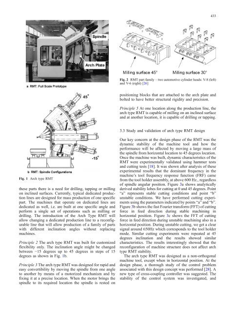
433Fig. 2 RMT part family – two automotive cylinder heads: V-8 (left)and V-6 (right) [26]positioning blocks that are attached to the arch plate andbolted to have better structural rigidity and precision.Principle 5 At one location along the production line, thearch type RMT is capable <strong>of</strong> milling on an inclined surfaceand at another location, it is capable <strong>of</strong> drilling or tapping.3.3 Study and validation <strong>of</strong> arch type RMT designFig. 1 Arch type RMTthese parts there is a need for drilling, tapping or millingon inclined surfaces. Currently, typical dedicated productionlines are designed for mass production <strong>of</strong> one specificpart. The <strong>machines</strong> that operate on dedicated lines arededicated as well, i.e. are built at one specific angle andperform a single set <strong>of</strong> operations such as milling ordrilling. The introduction <strong>of</strong> the Arch Type RMT willallow changing a dedicated production line to a <strong>reconfigurable</strong>line that will allow production <strong>of</strong> a family <strong>of</strong> partswith different inclination angles without replacing<strong>machines</strong>.Principle 2 The arch type RMT was built for customizedflexibility only. The inclination angle might be changedbetween −15 degrees up to 45 degrees in steps <strong>of</strong> 15degrees as shown in Fig. 1b.Principle 3 The arch type RMT was designed for rapid andeasy convertibility by moving the spindle from one angleto another by means <strong>of</strong> a motorized mechanism and byfixing it at a precise location. When the motor brings thespindle to its required location the spindle is rested onOur key concern at the design phase <strong>of</strong> the RMT was thedynamic stability <strong>of</strong> the machine tool and how theperformance will be affected by moving a large mass <strong>of</strong>the spindle from horizontal location to 45 degrees location.Once the machine was built, dynamic characteristics <strong>of</strong> theRMT were experimentally validated using hammer testsand cutting tests [18]. It was shown after analysis <strong>of</strong> theseexperimental results that the dominant frequency in themachine’s tool frequency response function (FRF) camefrom the tool holder assembly, at above 600 Hz., regardless<strong>of</strong> spindle angular position. Figure 3a shows analyticallyderived stability lobes for cutting at 0 and 45 degrees. Point“a” represents stable cutting conditions and point “b”unstable conditions. We have performed cutting experimentsusing the parameters indicated by points “a” and “b”.Figure 3b shows the fast Fourier transform (FFT) <strong>of</strong> cuttingforce in feed direction during stable machining inhorizontal position. Figure 3c shows the FFT <strong>of</strong> cuttingforce in feed direction during unstable machining also in ahorizontal position. During unstable cutting, we get a clearsignal around 650Hz which corresponds to the tool holdermode. Similar cutting experiments were repeated at 45degrees inclination and the results showed similarcharacteristics. The results interestingly showed that thereconfiguration <strong>of</strong> machine structure does not affect archtype RMT stability.The arch type RMT was designed as a non-orthogonalmachine tool, except when in horizontal position. At thedesign phase, a thorough study <strong>of</strong> the control problemassociated with this design concept was performed [28]. Anew type <strong>of</strong> cross-coupling controller was suggested. Thestability <strong>of</strong> the control system was investigated, and