435the required sampling density and inspection cycle time.The linear position along the axis <strong>of</strong> travel is recorded foreach measurement point, which enables a precise mapping<strong>of</strong> the part surface without being affected by variations inthe motion stage velocity.The RIM is intended for use in an industrial environment.It is located adjacent to the machining line with atotal cycle time including part transfer equal to that <strong>of</strong> themachining line, which is assumed to be around 40 seconds.Radio Frequency (RF) technology was demonstrated in thelaboratory for reading the RF tag located on the part fixtureto identify the specific part number to be evaluated. Uponcompletion <strong>of</strong> the measurements and feature evaluations,the results <strong>of</strong> the evaluation were stored on the RF tag andon the RIM database. A bock diagram <strong>of</strong> the RIM systemarchitecture is presented in Fig. 5.Fig. 6 RIM part family <strong>of</strong> engine cylinder headsmeasuring distance between two features centers atanother location along the line as presented schematicallyin Fig. 7.4.2 Application <strong>of</strong> RM design <strong>principles</strong> in RIMPrinciple 1 The RIM was built around a part family <strong>of</strong>engine cylinder heads that during mass-production needin-line inspection. Typical parts that belong to this partfamily are shown in Fig. 6. These engine cylinder headswere produced by different companies for different types<strong>of</strong> engines. However, all <strong>of</strong> them have common characteristicfeatures such as precisely machined flat surfaces,prismatic shape and a series <strong>of</strong> threaded holes.Principle 2 The RIM was built for customized flexibilityonly. The machine is capable <strong>of</strong> measuring variousfeatures <strong>of</strong> cylinder heads <strong>of</strong> various sizes; however, it isnot designed to measure all features <strong>of</strong> one part or tomeasure other parts that are not from the same part family.Principle 3 The RIM is designed for rapid and easyconvertibility by adding sensors when needed and bychanging the location <strong>of</strong> existing sensors as required forinspection <strong>of</strong> different parts or different features <strong>of</strong> thesame part.Principle 4 The RIM was designed to be scalable, i.e., toallow mounting <strong>of</strong> different probes at different locationsprepared at the outset. The scalability enables efficientmeasurements <strong>of</strong> different features.Principle 5 The RIM is capable <strong>of</strong> measuring surfaceflatness at one location along the production line andFig. 5 RIM system architecture4.3 Study and validation <strong>of</strong> RIM designIn this section, we demonstrate the RM design <strong>principles</strong>and their implementation as reflected in RIM design. Also,RIM performance as a non-contact inspection machine wasexperimentally validated.The <strong>reconfigurable</strong> inspection machine was designedaround a part family <strong>of</strong> engine cylinder heads as explainedearlier. To measure each <strong>of</strong> the heads, different fixtureswere designed and used. For each head, the location <strong>of</strong> thelaser sensors as well as the position <strong>of</strong> the vision systemwere reconfigured to capture all features <strong>of</strong> interest.The RIM can measure geometrical and dimensionalfeatures such as: flatness <strong>of</strong> a surface and parallelismbetween two surfaces, distance between surfaces distancebetween edges and related dimensional features. The RIMis not designed, however, to measure the roundness <strong>of</strong>parts, since roundness is not relevant for inspectingcylinder heads, which are prismatic parts. We have testedexperimentally the quality <strong>of</strong> RIM measurements. Table 1presents RIM repeatability experimental results tested innominal condition when measuring a reference part. Themeasurements show good nominal repeatability <strong>of</strong> theRIM.Currently, the coordinate measurement machine(CMM), is the standard tool for industrial inspection <strong>of</strong>machined parts. It uses a touch-probe with a 0.5 to 2.0-mmdiameter ball. Utilizing the ConoProbe sensor on RIM, itslaser beam has a typical diameter <strong>of</strong> 20μm. Therefore, onecan expect different readings when using these two types <strong>of</strong>sensors on machined surface with a non-perfect surfacefinish. In order to compare RIM measurement results withthe results <strong>of</strong> a coordinate measurement machine (CMM),the “virtual ball” method was developed and implemented[32]. It provides the interpretations <strong>of</strong> non-contact lasermeasurements as if they have been performed by a CMMtouch-probe. A comparison between measurements fromthe RIM and a CMM, and repeatability results from theRIM are presented in [33].Figure 4b shows a typical design-for-convertibility <strong>of</strong>the RIM structure and fixtures. The design included a series
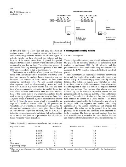
436Fig. 7 RIM integration onproduction line<strong>of</strong> threaded holes to allow fast and easy relocation <strong>of</strong>various sensors and accessories needed for inspection.While measuring different features on different types <strong>of</strong>cylinder heads, we have changed the fixtures and thelocation <strong>of</strong> the sensors many times. A typical time periodrequired for relocation <strong>of</strong> sensors when different heads aremeasured is less than an hour. The calibration process <strong>of</strong>the sensors following reconfiguration process <strong>of</strong> the RIM[34] was successfully tested in the laboratory.To demonstrate scalability <strong>of</strong> the system, the RIM wastested with a differing number <strong>of</strong> sensors. We started withtwo laser sensors for surface flatness inspection and weincreased the number <strong>of</strong> laser sensors to four whenmeasuring parallelism [35]. We also applied machinevision systems based on a line scanning camera and usedboth the 4 K and 8 K pixels versions. We could use eachtype <strong>of</strong> sensor separately or together in parallel during thescan <strong>of</strong> the cylinder head surface. One important application<strong>of</strong> the vision system was measuring surface defectssuch as casting originated pores on machined surfaces [36].A typical image <strong>of</strong> pores on cylinder head surface is shownin Fig. 8. Figure 8a shows a pore which is connected to anedge <strong>of</strong> a machined feature while Fig. 8b presents an“isolated pore”. For each pore <strong>of</strong> interest we can analyze itssize and the location relative to some given datum. Basedon our porosity inspection research, one <strong>of</strong> ERC/RMSindustrial partners is currently building a full-scale machineto be located and used on a production line <strong>of</strong> cylinderheads replacing visual inspection.5 Reconfigurable assembly machine5.1 Brief descriptionThe <strong>reconfigurable</strong> assembly machine (RAM) described inthis paper is an assembly machine for automotive heatexchangers (radiators) [37]. Dr. M. Mehrabi and hisgraduate students have conducted a study and conceptuallydesigned the RAM together with an ERC/RMS industrialpartner.Heat exchangers are rectangular matrices comprisingtubes and fins bordered by headers and side supports asshown in Fig. 9. The assembly process starts by feedingtubes and fins to the core-builder area. The tubes are in theform <strong>of</strong> stacks that are fed into the core-builder whereas thefins are supplied in trays that contain the required number<strong>of</strong> fins per radiator. The machine then places one tubefollowed by one fin from the respective sources and theprocess iterates till the required quantity <strong>of</strong> fins and tubes isreached. The collection <strong>of</strong> tubes and fins that are looselyheld together is termed as a ‘loose matrix’. This loosematrix is then transferred to the final assembly area where itis capped with side supports and headers after beingcompressed to the correct dimensions and checked foralignment. The tubes are to be pressed into the slotsprovided in the headers and therefore their alignment isfairly important. The finished product received from thefinal assembly area is termed as the ‘core’. Before the corecan be removed from the assembly area, it is constrained byTable 1 Repeatability measurements performed on a reference partInspection number Width Parallelism Joint face flatness Cover face flatness1 118,975.1 9.3 9.5 9.32 118,975.1 8.7 8.7 8.83 118,975.2 8.8 8.7 8.74 118,975.1 8.5 8.4 8.55 118,975.1 10.1 9.3 9.5Mean value 118,975.1 9.1 8.9 9.0Repeatability (range) 0.1 1.5 1.1 1.0Values are in μm. (Repeatability is defined as the difference between the max and min values in the range defined by the five inspectionsperformed)