Dirty Paper Coding using Sign-bit Shaping and LDPC Codes
Dirty Paper Coding using Sign-bit Shaping and LDPC Codes
Dirty Paper Coding using Sign-bit Shaping and LDPC Codes

Create successful ePaper yourself
Turn your PDF publications into a flip-book with our unique Google optimized e-Paper software.
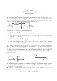
ISIT 2010, Austin, Texas, U.S.A., June 13 - 18, 20101000 100110111010111011111101110000000001001100100110011101010100-15/2 -13/2 -11/2-9/2-7/2-5/2-3/2-1/21/23/25/27/29/211/213/215/2Fig. 1.16-PAM constellation.n − sParity plus MessageBitsk ′MessageBits✲H −1Ts = nlog2MBits✲❄<strong>Shaping</strong> CoderViterbiAlgorithmminimizes theenergy of(v − αS) mod MsShapedBits✲<strong>LDPC</strong>Encoderof rate(k − k ′ + s) /n✲ Delay ✲n − (k − k ′ + s)ParityBits✲k − k ′Message <strong>bit</strong>s∏✲a b cMappingtoM − PAMmap (zabc)v−αS✓✏ ❄✲ ∑✒✑❄mod M✲(k − k ′ )MessageBits✻sShaped Bitsz❄(v − αS) mod MFig. 2.Encoder structure.<strong>and</strong> p T −1 are rearranged by a permutation Π to form thevectors a j , 2 ≤ j ≤ l. This permutation is necessary in animplementation of BICM [11].Note that both the shaping <strong>and</strong> coding objectives havebeen met at the encoder. The transmitted symbols v − αSmod M have minimal energy in the lattice defined by sign<strong>bit</strong>shaping <strong>using</strong> the convolutional code. Selected <strong>bit</strong>s insuccessive blocks of symbols form codewords of the <strong>LDPC</strong>code. In summary, the encoder structure achieves DPC shaping<strong>and</strong> <strong>LDPC</strong> coding with <strong>bit</strong>-interleaved modulation.B. Decoder StructureThe decoder for the proposed scheme is as shown in Fig.3.Because of the one-codeword delay, parity <strong>bit</strong>s of the T +1-th block <strong>and</strong> message plus shaped <strong>bit</strong>s of the T -th blockform a valid <strong>LDPC</strong> codeword. Therefore, an <strong>LDPC</strong> decoderis first run on these symbols corresponding to a codeword. Thedecoded shaped <strong>bit</strong>s are passed through a syndrome former toget message <strong>bit</strong>s used for shaping. Iterations between shapingdecoder <strong>and</strong> channel decoder are not needed. The demappercomputes log likelihood ratios (LLRs) for the <strong>bit</strong>s from thereceived symbols in Ŷ = αY + U. The LLRs of the (k − k′ )message <strong>bit</strong>s after a delay of one time step, <strong>and</strong> the LLRs of then−(k − k ′ + s) parity <strong>bit</strong>s are de-interleaved. The s =nlog 2MLLRs of the sign <strong>bit</strong>s after a delay on one time step, <strong>and</strong> then−s output LLRs of the de-interleaver are given as the input tothe <strong>LDPC</strong> decoder. The <strong>LDPC</strong> decoder outputs k−k ′ message<strong>bit</strong>s <strong>and</strong> s <strong>bit</strong>s of the sign <strong>bit</strong> vector of the previous block. Now,the s-<strong>bit</strong> sign vector is passed through the syndrome formerto recover the remaining k ′ message <strong>bit</strong>s.The demapper function at the receiver has to calculate LLRstaking into account the modulo M operation at the encoder [4].Therefore, the received constellation A R is a replicated versionof the M-PAM constellation A used at the transmitter (assumingthat scaling factors have been corrected at the receiver).That is, A R = {A−rM, ··· ,A−M, A, A+M,··· ,A+rM}.The number of replications r is chosen so that the averagepower of A R is approximately equal to the total averagepower P X + P S , <strong>and</strong> the <strong>bit</strong> mapping of the symbol a + jM(a ∈ A, 1 ≤ j ≤ r) is the same as that for a. The LLR forthe i-th <strong>bit</strong> in the j-th symbol Ŷj is computed according tothe constellation A R <strong>using</strong> the following formula:⎛2⎞∑(Ŷj⎜exp ⎝− 1 − a)⎟⎠2 αP NL i =a∈A R:<strong>bit</strong> i=0∑a∈A R:<strong>bit</strong> i=1⎛⎜exp ⎝− 1 22⎞.(Ŷj − a)αP N⎟⎠925
ISIT 2010, Austin, Texas, U.S.A., June 13 - 18, 2010Ŷ = αY + U✲Demappern − (k − k ′ + s)LLRs ofParity Bits✲∏ −1✲ Delay ✲ ✲(k − k ′ )LLRs of Message Bitsnlog2MLLRs of sign <strong>bit</strong>s✲✲ Delay ✲<strong>LDPC</strong>DecodersBits k ′✲H T ✲✲MessageBitsk − k ′MessageBitsFig. 3.Decoder structure.Since the constellation mapping is nearly Gray, iterationswith the demapper do not provide significant improvementsin coding gain, particularly for large M.IV. SIMULATION RESULTSFor simulations, we have taken n = 40000, k = 30000,k ′ = 5000 with M = 16; this results in s = 10000.The constellation mapping is as given in Fig. 1. Wehave chosen a rate-1/2 memory 8 (256 state) nonsystematic( convolutional code with generator polynomialsD 8 + D 5 + D 4 + D 2 + D +1,D 8 + D 7 + D 4 + D 2 +1 )as the sign-<strong>bit</strong> shaping code. A non-systematic convolutionalcode is used to avoid error propagation problems.A r<strong>and</strong>omly constructed irregular <strong>LDPC</strong> code (40000,35000) of rate 7/8 with variable node degree distribution0.1256x+0.7140x 2 +0.1604x 9 <strong>and</strong> check node degree distributionx 31 is used as the channel code. We considered severalc<strong>and</strong>idate distributions originally designed for BPSK overAWGN, <strong>and</strong> chose the one that provided the best performance.The overall rate of transmission is seen to be 3000040000 × 4=3<strong>bit</strong>s per channel use. Fig. 4 shows BER plots over an AWGNchannel <strong>and</strong> a DPC channel with interference known at thetransmitter. The interfering vector was generated at r<strong>and</strong>omBit error rateAWGNDPCCapacity for 3 <strong>bit</strong>s/sym10 −310 −410 −510 10.5 11 11.5 12 12.5 1310 −2 Eb/N0(dB)Fig. 4.BER plot for DPC <strong>and</strong> AWGN.for different power levels. The plot with interference did notchange appreciably for all power levels of interference, <strong>and</strong>we have provided one plot for illustration. We see that a BERof 10 −5 is achieved at an SNR of 19.45dB with interference,<strong>and</strong> at an SNR of 19.33 dB without interference. We havesimulated 1000 blocks of length 40000 to obtain sufficientstatistics for a BER of 10 −5 .The AWGN capacity at an SNR of 10 log 10 (2 6 −1)=17.99dB for a rate of 3 <strong>bit</strong>s per channel use. This shows that weare 1.46 dB away from ideal dirty paper channel capacity.The granular gain G(Λ)=2 2R /6S x is computed from thesimulations to be 1.282dB [4], where R = 3.5 is the ratebefore channel coding, <strong>and</strong> S x is the transmit power (obtainedthrough simulations). From this, the shaping loss is calculatedas follows:2πeG (Λ) 2 2C∗ − 110log 10 =0.2548 dB, (7)2 2C∗ − 1where C ∗ = 3. So, of the total gap of 1.46 dB, we havea shaping gap of 0.2548dB, <strong>and</strong> a coding gap of 1.2052dBto capacity. We observed that trellis shaping with largernumber of states results in a decrease in shaping loss in othersimulations.V. APPLICATION TO GAUSSIAN BROADCAST CHANNELWe use the proposed scheme for superposition coding ina two-user Gaussian broadcast channel Y 1 = X + N 1 <strong>and</strong>Y 2 = X + N 2 with P N1 >P N2 . We let P X1 =(1− β) P<strong>and</strong> P X2 = βP, where P is the total transmit power. Here,User 2 is coded <strong>using</strong> DPC considering User 1 as interference.User 1 is shaped <strong>using</strong> sign-<strong>bit</strong> shaping <strong>and</strong> coded <strong>using</strong> an<strong>LDPC</strong> code over M-PAM. Fig. 5 shows a block diagram ofthe transmitter <strong>and</strong> receivers. The encoder structure for User1 is as in Fig. 2 with the interference vector S = 0. Hence,for User 1, the shaping coder minimizes the energy of v. Thedemapper at Receiver 1 calculates LLR for the i-th <strong>bit</strong> in thej-th receiver symbol Y 1j <strong>using</strong> the following formula.∑a∈A:<strong>bit</strong> i=0L i =p(a) exp{− 1 (Y 1j−a) 22 βP+P N1}∑a∈A:<strong>bit</strong> i=1 p(a) exp{− 1 (Y 1j−a) 22 βP+P N1} ,where p(a) for a ∈ A represents the a priori probability of theM-PAM symbol a. At the receiver, we approximate p i <strong>using</strong>926
ISIT 2010, Austin, Texas, U.S.A., June 13 - 18, 2010User 1Message <strong>bit</strong>s Shaped <strong>and</strong>✲<strong>LDPC</strong> codedX1as S forUser 2❄User 2Message <strong>bit</strong>s✲ DPC codedX1✓✏ ❄ ∑ X✒✑✻X2 ✒Y1 = X + N1✲ ❅❅❅❅❅Y2 = X + N2 ❅❅❅❘Receiver 1Receiver 2R 1(Rate of User 1 in <strong>bit</strong>s/channel use)54.543.532.521.5(3, 3.409)(3, 3)(2.474, 3)(3.451, 3)(3, 2.608)Broadcast capacityTime sharingFig. 5.Block diagram for a two-user Gaussian broadcast channel.10.5a Gaussian distribution with variance P S assuming that thedistribution of M-PAM symbols is approximately Gaussian.We simulated a two user degraded broadcast channel withP N1 =0.9 <strong>and</strong> P N2 =0.09 <strong>using</strong> the proposed scheme withparameters from Section IV. The total transmit power, powerfor User 1 <strong>and</strong> power for User 2 required for a <strong>bit</strong> error rate of10 −5 (at both receivers) are estimated from the simulation <strong>and</strong>denoted P , P x1 <strong>and</strong> P X2 , respectively. ( ) The SNR for ReceiverPX11 is computed as 10 log 10 P X2 +P N1=19.1791 dB. SinceDPC is done for User 2, ( the)effective SNR at Receiver 2PX2is computed as 10 log 10 P N2=19.4574 dB. Comparisonwith the SNR needed for a single user capacity of 3 <strong>bit</strong>s perchannel use (which is 17.99 dB) shows that the total loss forboth the users is about 2.4642dB. Fig. 6 shows the (3, 3) ratepair in the capacity region of the two-user Gaussian broadcastchannel with total transmit power P <strong>and</strong> ( noise power P N1 ,P N2 , which is defined by R 1 ≤ 1 2 log 1+ (1−β)PβP+P N1), R 2 ≤( )12 log 1+ βPP N2for 0 ≤ β ≤ 1. We see that the (3,3) ratepoint is clearly outside the time-sharing region.VI. CONCLUSIONSIn this work, we have proposed a method for designinglattice-based schemes for dirty paper coding <strong>using</strong> sign-<strong>bit</strong>shaping <strong>and</strong> <strong>LDPC</strong> codes. Simulation results show that theproposed design performs 1.46dB away from the dirty papercapacity for a block length of n = 40000 at the rate of3 <strong>bit</strong>s/channel use. This performance is comparable to otherresults in the literature. However, as discussed in this article,a novel method for combining shaping <strong>and</strong> coding resultsin good gains at lesser complexity in our design, whencompared to other lattice-based strategies. As an application,we have designed a superposition coding scheme for Gaussianbroadcast channels that is shown to perform better than timesharingthrough simulations.Out of the 1.46 dB gap to capacity, about 1.2 dB is gapattributed to a sub-optimal choice of the <strong>LDPC</strong> code <strong>and</strong> arelatively low blocklength. Optimizing the <strong>LDPC</strong> code <strong>using</strong>genetic algorithms <strong>and</strong> asymmetric density evolution [12]00 1 2 3 4 5 6 7Fig. 6.R 2(Rate of User 2 in <strong>bit</strong>s/channel use)Two-user Gaussian broadcast channel capacity region.along with joint optimization of shaping code <strong>and</strong> <strong>LDPC</strong> code<strong>using</strong> EXIT charts [8] are topics for future work.REFERENCES[1] M. Costa, “Writing on dirty paper (corresp.),” Information Theory, IEEETransactions on, vol. 29, no. 3, pp. 439–441, May 1983.[2] T. Philosof, U. Erez, <strong>and</strong> R. Zamir, “Combined shaping <strong>and</strong> precodingfor interference cancellation at low snr,” in Information Theory, 2003.Proceedings. IEEE International Symposium on, June-4 July 2003, pp.68–.[3] U. Erez, S. Shamai, <strong>and</strong> R. Zamir, “Capacity <strong>and</strong> lattice strategies forcanceling known interference,” Information Theory, IEEE Transactionson, vol. 51, no. 11, pp. 3820–3833, Nov. 2005.[4] U. Erez <strong>and</strong> S. Brink, “A close-to-capacity dirty paper coding scheme,”Information Theory, IEEE Transactions on, vol. 51, no. 10, pp. 3417–3432, Oct. 2005.[5] S.-Y. Chung, “Multi-level dirty paper coding,” Communications Letters,IEEE, vol. 12, no. 6, pp. 456–458, June 2008.[6] Y. Sun, M. Uppal, A. Liveris, S. Cheng, V. Stankovic, <strong>and</strong> Z. Xiong,“Nested turbo codes for the costa problem,” Communications, IEEETransactions on, vol. 56, no. 3, pp. 388–399, March 2008.[7] M. Uppal, V. Stankovic, <strong>and</strong> Z. Xiong, “Code design for mimo broadcastchannels,” Communications, IEEE Transactions on, vol. 57, no. 4, pp.986–996, April 2009.[8] Y. Sun, Y. Yang, A. Liveris, V. Stankovic, <strong>and</strong> Z. Xiong, “Nearcapacitydirty-paper code design: A source-channel coding approach,”Information Theory, IEEE Transactions on, vol. 55, no. 7, pp. 3013–3031, July 2009.[9] Y. Sun, A. Liveris, V. Stankovic, <strong>and</strong> Z. Xiong, “Near-capacity dirtypapercode designs based on tcq <strong>and</strong> ira codes,” in Information Theory,2005. ISIT 2005. Proceedings. International Symposium on, Sept. 2005,pp. 184–188.[10] J. Forney, G.D., “Trellis shaping,” Information Theory, IEEE Transactionson, vol. 38, no. 2, pp. 281–300, Mar 1992.[11] G. Caire, G. Taricco, <strong>and</strong> E. Biglieri, “Bit-interleaved coded modulation,”IEEE Trans. on Info. theory, vol. 44, no. 3, pp. 927–946, May1998.[12] C.-C. Wang, S. Kulkarni, <strong>and</strong> H. Poor, “Density evolution for asymmetricmemoryless channels,” Information Theory, IEEE Transactions on,vol. 51, no. 12, pp. 4216–4236, Dec. 2005.927