Download Installation Manual (.pdf) - Heat Transfer Products, Inc
Download Installation Manual (.pdf) - Heat Transfer Products, Inc
Download Installation Manual (.pdf) - Heat Transfer Products, Inc

Create successful ePaper yourself
Turn your PDF publications into a flip-book with our unique Google optimized e-Paper software.
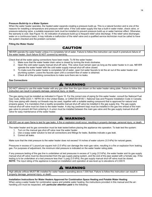
14Pressure Build-Up in a Water SystemWhen the water heater operates, the heated water expands creating a pressure build-up. This is a natural function and is one of thereasons for installing a temperature and pressure relief valve. If the cold water supply line has a built-in water meter, check valve, orpressure-reducing valve, a suitable expansion tank must be installed to prevent pressure build-up or water hammer effect. Otherwise,the warranty is void. See Figure 10. An indication of pressure build-up is frequent relief valve discharge. If the relief valve dischargeswater on a continuous basis, it may indicate a malfunction of the relief valve and a qualified service technician must be called to havethe system checked and the problem corrected.Filling the Water <strong>Heat</strong>erNEVER operate the water heater unless it is completely full of water. Failure to follow this instruction can result in premature failure ofthe water heater. Such failure IS NOT covered by warranty.Check that all the water piping connections have been made. To fill the water heater:1. Make sure that the water heater drain valve is closed by turning the knob clockwise.2. Open the cold water supply manual shut-off valve. This valve must remain open as long as the water heater is in use. NEVERoperate the water heater with the cold water supply manual shut-off valve closed.3. To make sure the water heater is completely full of water, open hot water faucets to let the air out of the water heater andplumbing system. Leave the faucets open until a constant flow of water is obtained.4. Check all of the plumbing connections to make sure there are no leaks.Gas ConnectionsDO NOT attempt to use this water heater with any gas other than the type shown on the water heater rating plate. Failure to follow thisinstruction can result in property damage, personal injury, or death.The gas piping must be installed as indicated in Figure 10. For the correct size of piping for this water heater, consult the National FuelGas Code, ANSI Z223.1 / NFPA 54 in the United States, or CAN/CSA B149.1, National Gas and Propane <strong>Installation</strong> Code in Canada.Only new piping with cleanly cut threads may be used, together with a suitable sealing compound that is approved for natural andpropane gases. It is mandatory that a readily accessible manual shut-off valve be installed in the gas supply line. The gas supplymanual shut-off valve must be close to the water heater. A drip leg (sediment trap) must be installed in the gas line ahead of the maingas valve to prevent dirt from entering it. A union must be installed between the main gas valve and the gas supply manual shut-offvalve for easy maintenance of the water heater.NEVER use an open flame to test for gas leaks. A fire or explosion could occur, resulting in property damage, personal injury, or death.The water heater and its gas connection must be leak tested before placing the appliance into operation. To leak test the system:1. Turn on the manual gas shut-off valve near the water heater.2. Use a soapy water solution to test all connections and fittings for leaks. Bubbles indicate a gas leak.3. Correct all leaks.Make sure that the inlet pressure to the water heater does not exceed 14 inches of water column (3.5 kPa) for natural gases.Pressures in excess of ½ pound per square inch (3.5 kPa) can damage the main gas valve, resulting in a fire or explosion from leakinggas. For purposes of adjustment, the minimum inlet pressure is indicated on the water heater rating plate.If any pressure testing of the gas line is undertaken at test pressures in excess of ½ psig (3.5 kPa), the water heater and its gas supplymanual shut-off valve must be disconnected from the gas supply piping system, and the end of the pipe sealed with a female cap. If thetesting is to be undertaken at a test pressure less than ½ psig (3.5 kPa), the gas supply manual shut-off valve must be closed.NOTE: The input rating of the appliance is based on installation and operation at sea level up to elevations of 2,000 ft.High altitude orifices MUST BE installed for water heaters operating above 7,500 feet. Failure to follow this instruction can result inproperty damage, personal injury, or death.<strong>Installation</strong> Instructions for Water <strong>Heat</strong>ers Approved for Combination Space <strong>Heat</strong>ing and Potable Water <strong>Heat</strong>ingWhen using a water heater for combination space and potable water heating, the instructions provided in this manual and the airhandlingunit must be respected, with particular attention paid to the following: