LVWO Waste Oil Boiler - Columbia Heating
LVWO Waste Oil Boiler - Columbia Heating
LVWO Waste Oil Boiler - Columbia Heating

Create successful ePaper yourself
Turn your PDF publications into a flip-book with our unique Google optimized e-Paper software.
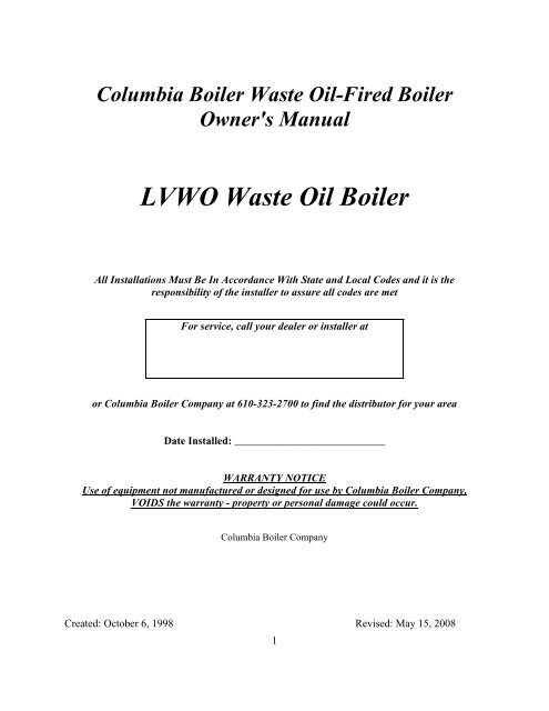
<strong>Columbia</strong> <strong>Boiler</strong> <strong>Waste</strong> <strong>Oil</strong>-Fired <strong>Boiler</strong>Owner's Manual<strong>LVWO</strong> <strong>Waste</strong> <strong>Oil</strong> <strong>Boiler</strong>All Installations Must Be In Accordance With State and Local Codes and it is theresponsibility of the installer to assure all codes are metFor service, call your dealer or installer ator <strong>Columbia</strong> <strong>Boiler</strong> Company at 610-323-2700 to find the distributor for your areaDate Installed: ____________________________WARRANTY NOTICEUse of equipment not manufactured or designed for use by <strong>Columbia</strong> <strong>Boiler</strong> Company,VOIDS the warranty - property or personal damage could occur.<strong>Columbia</strong> <strong>Boiler</strong> CompanyCreated: October 6, 1998 Revised: May 15, 20081
TABLE OF CONTENTSSUBJECTPAGEPACKING LIST 3SYSTEM INSTALLATION 4BURNER, PUMP AND CHIMNEY 6BURNER COMPONENTS 8AIR AND OIL SUPPLY 11ELECTRICAL 13WIRING DIAGRAMS 14START-UP 17FINE TUNING THE BURNER 18PRIMARY CONTROL FUNCTIONS 19BURNER MAINTENANCE 20BOILER MAINTENANCE 27PRODUCT SPECIFICATIONS 32BOILER ROOM REQUIREMENTS 34BOILER CONTROLS 36TROUBLE SHOOTING 39PARTS LIST 41APPENDIX A: <strong>Boiler</strong> Piping DiagramAPPENDIX B: Aquastat Control InstructionsWARRANTY2
PACKING LISTAll units should be inspected for damage upon arrival. Concealed damage claimsshould be filed immediately with the carrier by the consignee. The carrier isresponsible for taking prompt action on all claims.1 <strong>Boiler</strong> / B-5 Burner and Burner Cord1 Stainless Steel Chamber Liner (Installed)1 Temp/Pressure Gage (Mounted)1 ASME Relief Valve1 Operating Aquastat / 1 High Limit Aquastat (Mounted)1 <strong>Boiler</strong> Manual1 <strong>Boiler</strong> tube brush1 <strong>Oil</strong> Pump1 Pump / Filter Kit1 Tank Suction Strainer1 Filter with Vac / Air Gage1 Vac / Air Gage1 of each: 3/4X1/2 FPT Swivel, ¼ X ¼ X 1/8, Tee, ¼ NPT Hex Nipple, ¼ Nipple,½ Nipple, ¾ Check Valve, ¾ Shut Off Valve1 Junction Box with Cover and Terminal Strip3
SYSTEM INSTALLATION PROCEDURE1) Select a location for your boiler observing minimum clearance to combustibles. See“<strong>Boiler</strong> Room Requirements” in this manual. Consider that maintenance and cleaningwill be required. Allow adequate work space around burner and stack. Three feet ofclearance on around all surfaces is recommended.2) Mount boiler on a non-combustible level surface and observe minimum clearances tocombustibles. Elevating the boiler on non-combustible blocks will make maintenanceeasier. For clearances less than listed below, consult NFPA-31.Minimum Clearance to combustible MaterialsSides: 2”Rear: 2” (Allow clearance to remove rear door for cleaning, approx. 18 in.)Front: 12” (Allow clearance to open swing door for cleaning, approx. 22 in.)Chimney Connector: 6”3) See the piping layout diagram (Appendix A.) for suggested piping arrangement. Theboiler is equipped with a built in air scoop. This feature allows quiet air free operation ofyour hot water system by assuring removal of air pockets without the use of Air Scoopdevices. The 1 ¼” supply fitting on the top of the boiler extends approximately 1” belowthe top of the boiler, thus allowing only air-free water to enter the supply. An AutomaticFloat Vent, provided by others, must be installed on the ¾” vent tapping, as shown in thepiping diagram to vent trapped air.4) For best operation minimize distance of horizontal chimney runs. Do not exceed 8' inlength. Horizontal runs must have a 1/4" rise per foot. Clean horizontal runs every500 hours of use or as needed. Ash will accumulate here and block draft. Poor draftcauses poor flame, backpressure, oily buildup, unreliable ignition.5) WASTE OIL BOILERS ARE DEPENDENT ON PROPER DRAFT FOR EFFICIENTBURNING. ASSURE THAT ADEQUATE MAKE-UP AIR IS AVAILABLE. NEGATIVEDRAFT REQUIREMENT: -.04 to -.06 IN. OF WATER COLUMN BETWEEN THEBOILER OUTLET AND THE DRAFT REGULATOR AND APPROX -.02 OVER THEFIRE. BUILDING EXHAUST FANS OR COLD BUILDING TEMPS. AT NIGHT CANREVERSE YOUR DRAFT AND CAUSE FUMES, POOR COMBUSTION, OR BURNERLOCKOUTS. TAKE MEASURES TO ASSURE BOILER WILL HAVE PROPER DRAFTDIRECTION WHEN OPERATING.6) CHECK DRAFT AFTER START-UP AND STEADY STATE. THEN CHECK BYOPENING DOORS AND STARTING VENT FANS TO ASSURE THAT DRAFTREGULATOR CAN MAINTAIN -.04 TO -.06 UNDER ALL CONDITIONS. A SECONDREGULATOR MAY BE NEEDED IF DRAFT CAN NOT BE MAINTAINED. A DRAFTREGULATOR IS REQUIRED ON ALL INSTALLATIONS. A DRAFT INDUCER ISRECOMMENDED WHEN THERE IS INSUFFICIENT DRAFT.4
7) If permanent masonry chimney is not available, use appropriate diameter multi-wallmanufactured chimney and collars listed for use with oil fired boilers per UL 103 or AllFuel Class A. Locate for easy connection to the boiler and install per manufacturers'instructions and local building and fire codes. Proper burner settings and normaloperation will produce a gross chimney temperature between 400°F and 600°F.8) The chimney must extend a minimum of 3' above the highest roof line within 10'.In general you will need a minimum of 2 feet of vertical for each foot of horizontalfor best draft.9) Use a stack that is equal diameter to the boiler outlet (5 in.). Use minimum 24 gaugesingle wall connector pipe between boiler outlet and damper. Do not allow rain to comedown the chimney and have a path into fire chamber. This will create an environment thatwill promote rust. Install a chimney tee near the boiler to act as a cleanout / water trap.10) Locate barometric damper (draft regulator) near the boiler. Its opening must bevisible from the floor and out of strong airflows that could falsely affect its ability toregulate.10) Adequate air must be provided for combustion and ventilation. In buildings of tightconstruction, you should provide an opening connected to a well ventilated space, or theoutdoors. The opening should have a free area of 1 square inch per 1,000 Btu per hourfor all appliances located in the space. <strong>Boiler</strong>s installed in confined spaces should havetwo ventilation openings each with a free area of 1 square inch per 1,000 Btu per hour forall confined appliances. One opening should be near the top of the space and the othernear the bottom. An air boot kit is available from your <strong>Columbia</strong> dealer for outside air.11) The LV <strong>Waste</strong> <strong>Oil</strong> <strong>Boiler</strong> is equipped with a hinged burner swing open door. The dooris installed to open from the right to the left. Take care to install all wiring, fuel andair lines so that the door can be opened without disturbing the lines. See Burnersection in this manual for installation information.IMPORTANTThe hinged burner door is opened by removing the six 3/8” brass nuts locatedon the top, bottom and right side of the door. The two brass nuts located onthe left side hold the door to the hinge. Do not loosen or remove the brassnuts holding the door to the hinge after the burner is installed.5
BURNER , PUMP, & CHIMNEYPUMP SPECIFICATIONS'A' Pump'J' Pump1/4 " FNPT Inlet Port 1/2 " FNPT1/8 “ FNPT Outlet Port 1/4 " FNPT40-60 PSI Pressure Range 20-40 PSI6 GPH Max. Flow 18 GPH1725 RPM Speed 1725 RPM1/4 HP 1/4CW Shaft End Rotation CW Shaft End20” Hg Max Operating Vacuum 20" Hg10’ Vertical Maximum Suggested Lift 10' Vertical3/4” pipe Horizontal Suction Piping < 30 Ft. 3/4”pipe1” pipe Horizontal Suction Piping > 30 Ft. 1" pipeINTRODUCTIONPurchase of a <strong>Columbia</strong> multi-oil burner is a wise investment. To maximize the return onthis investment you must read and save this manual. It contains installation instructions,diagnostic procedures, burner cleaning, maintenance procedures and parts orderinginformation. Follow the installation instructions carefully.You can expect years of reliable performance with a properly installed and maintained system.THIS BURNER IS NOT INTENDED FOR RESIDENTIAL USE.It shall be installed only by a qualified installer who is engaged in, responsible for orthoroughly familiar with the permitting, installation and operation of oil-fired appliances;who is experienced in such work and is familiar with the precautions required; and whowill comply with all the requirements of the Authority having jurisdiction over theinstallation.The installation of equipment in the United States must consider the requirements of thefollowing publications of the National Fire Protection Association, Battery March Park,Quincy, Massachusetts 02269:N.F.P.A. No. 30 Flammable and Combustible Liquid CodesN.F.P.A. No. 31 Standard for Installation of <strong>Oil</strong> Burning EquipmentN.F.P.A. No. 88A Standard for Parking StructuresN.F.P.A. No. 88B Standard for Repair GaragesN.F.P.A. No. 211 Standard for Chimney, Fireplaces, Vents and Solid Fuel BurningAppliances6
The installation of Equipment in Canada must consider the requirements of C.S.A., Standard B139, Installation Code for <strong>Oil</strong> Burning Equipment.This burner is recommend for burning #1 & #2 fuel oil, used motor oil, automatictransmission fluid, hydraulic oil, vegetable oil and gear oil mixed not to exceed SAE 50.Such oils may contain gasoline and specific precautions on the handling and storage ofwaste oils are to be observed.Do Not add to oil supply or burn: unknown garbage oils, gasoline, naptha, chlorinated cleaningsolvents or oil additives in this boiler. It is normal to experience operating problems such asplugged nozzles, suction line leaks, etc. during the first few weeks of use. Follow start-upinstructions for purging fuel and air lines to help avoid these problems.7
BURNER COMPONENTS IDENTIFICATIONIGNITION CONTROL (PRIMARY CONTROL)HEADOIL REGULATOR W/OIL CONNECTIONCOMBUSTION AIR INLET BANDSBURNER MOUNT FLANGEFLAME RETENTIONIGNITOR / TRANSFORMERRESET BUTTONPRIMING SWITCHOIL, NOZZLE PRESSURESLIDE GUN ASSEMBLYAIR CONTROL BOXINDICATOR LIGHTS (3)AIR REGULATOR (COMPRESSED AIR)COMPRESSED AIRSUPPLY CONNECTIONAIR, NOZZLE PRESSURE8
FIELD ASSEMBLY INSTRUCTIONS - BURNER1/8” end nozzle to end electrode Upper fins are open to allow light to cad cell7/16” center of nozzle to electrode 5/32” closest gap1) PRIOR TO INSTALLING BURNER, CHECK FOR SHIPPING DAMAGE TOFLAME RETENTION HEAD AND IGNITION ELECTRODE ALIGNMENT.2) If components are not as shown you can make adjustments to the electrodes by removingthe hole plug on top of burner tube near mount flange. With screw driver, loosen thescrew holding the electrode clamping plate. Adjust electrodes as shown. Re-tightenclamp screw. Do not over tighten or insulation on electrodes may crack. Examineelectrode position after tightening to be sure position has not changed. Replace holeplug.3) The electrodes should not touch surrounding metal parts or be within 3/16” as they willshort the arc and not light the oil spray.4) Attach burner to boiler. Grasp burner by the mount flange and motor, slip burner flangeover studs on hinged burner door and secure with nuts and washers.9
INSTALLATION OF CHIMNEY SYSTEMINSTALL CHIMNEY TO FLUE COLLAR OF BOILERFor best operation minimize distance of horizontal chimney runs. Do not exceed 8' in length.Horizontal runs must have a 1/4" rise per foot. Clean horizontal runs every 500 hours ofuse or as needed. Ash will accumulate here and block draft. Poor draft causes poorflame, backpressure, oily buildup, and unreliable ignition.WASTE OIL BOILERS ARE DEPENDENT ON PROPER DRAFT FOR EFFICIENTBURNING. ASSURE THAT ADEQUATE MAKE-UP AIR IS AVAILABLE. NEGATIVEDRAFT REQUIREMENT: -.04 to -.06 IN. OF WATER COLUMN BETWEEN THE BOILEROUTLET AND THE DRAFT REGULATOR AND APPROX -.02 OVER THE FIRE.BUILDING EXHAUST FANS OR COLD BUILDING TEMPS. AT NIGHT CAN REVERSEYOUR DRAFT AND CAUSE FUMES, POOR COMBUSTION, OR BURNER LOCKOUTS.TAKE MEASURES TO ASSURE BOILER WILL HAVE PROPER DRAFT DIRECTIONWHEN OPERATING. A DRAFT REGULATOR IS REQUIRED. A DRAFT INDUCER ISRECOMMENDED WHEN THERE IS INSUFFICIENT DRAFT.If permanent masonry chimney is not available, use appropriate diameter multi-wallmanufactured chimney and collars listed for use with oil fired boilers per UL 103 or All FuelClass A. Locate for easy connection to the boiler and install per manufacturers' instructionsand local building and fire codes. Proper burner settings and normal operation will producea gross chimney temperature between 400°F and 600°F with a clean boiler.The chimney must extend a minimum of 3' above the highest roof line within 10'. Ingeneral you will need a minimum of 2 feet of vertical for each foot of horizontal flue forbest draft.Use a stack that is equal diameter to the boiler outlet (5-in.). Use minimum 24-gaugesingle wall connector pipe between boiler outlet and damper. Do not allow rain to comedown the chimney and have a path into fire chamber.If necessary, a draft inducer should be used to provide adequate draft conditions and shouldbe placed as near the building flu exit as possible. Inducers will pull air better than push it.Smaller inducers will not be adequate in some chimney installations. A draft regulator mustbe used in conjunction with a draft inducer.• Confirm local building codes will allow inducers• Locate inducer as close to where chimney exits building as practical• Never allow rain or condensation to flow back into boiler• Place a screen (1/2” or 3/4” openings) over stack to keep animals out• Observe clearance to combustible materials10
COMPRESSED AIR SUPPLY1. A minimum 2 CFM at 40 psi is needed into the burner. Use a hydraulic quick disconnector put ample flex in the line to swing burner open when servicing. A dedicated aircompressor at the boiler in lieu of using the shop’s air system is acceptable. A compressorof ¾ to 1½ HP is typical. Consult <strong>Columbia</strong> <strong>Boiler</strong> or your installer for models available.Drain all compressors frequently to help keep moisture from entering burner.2. Many burner service problems are from “rusty” air causing burner components to fail. Itis wise to use a oiler and/or regulator to treat & reduce air pressure entering the burner toapproximately 60 psi. Wear on burner parts will be reduced and ignition more reliable.Providing a drip leg with valve near the burner to trap water, scale, and rust isrecommended. If water is present take all measures to remove it. The air solenoid maystick and other components may rust and fail.3. SERVICE TIP: 80% of service problems can be avoided by keeping contaminants likerust chips, water, pipe dope, insects from reaching burner through the air and oil lines.OIL PUMP MOUNTING1. Consult your dealer for best plumbing methods before starting. Mount the pump asnear the oil supply tank as possible. You may mount the pump above the tank to suctionlift oil to the pump or another option is to place the pump below the tank level to gravityfeed or siphon oil to the pump. Do not exceed 10 psi into the pump inlet in anyarrangement or the seal may leak. Allow space for service. Be sure to meet allbuilding and fire code requirements.2. Any pump/motor orientation is acceptable as long as the pump shaft is horizontal. Youmay rotate the pump head on the mount to simplify plumbing connections. Be sure themotor and pump shafts are aligned and coupling set screws are tight before operating.Above Tank MountBelow Tank Level Mount<strong>LVWO</strong> Manual Page 11 of 48
FINISHING THE PLUMBING…….J PumpA Pump1/4” Outlet Air Bleeder 1/2” Inlet Air Bleeder 1/4” Inlet 1/8” Outlet[ If Using a CDVF Pump follow instructions in CDVF Manual ]Consult your dealer for the best plumbing arrangement for your boiler. There are many waysthe plumbing can be done. Use pipe dope on threads, not tape ! Flared tubing &fittings are acceptable, never use compression fittings ! Meeting building codes and yourneeds may require deviation from the fittings provided in your accessory carton and described inthe example below. Components shown are provided with standard purchases and found inAccessory Carton. Note: Some J pumps will have dual ½ “ inlets. Pipe to only one inlet.3/4 FPT Filter Gauges 3/4x1/2 Swivel 1/2 Nipple Pump 1/4 Nipple 1/4x1/4x1/8Tee<strong>Oil</strong> Regulator on Burner1/4 NippleSuction Strainer 3/4 FPT Check Valve 1/2 FPT Valve 1/2x1/4 Swivel<strong>LVWO</strong> Manual Page 12 of 48
Suction Line: Field provides piping from Check Valve to Filter. Secure piping to keep theStrainer 6” off the bottom of the tank. Plan ahead for routine service of components. Useminimal number of fitting to reduce chances of suction leaks. Note: Some J Pumps have dualsuction ports. It is only necessary to pipe to one of these ½ inches ports.Pressure Line (<strong>Oil</strong> Pump Outlet): After the provided Nipple/Tee/Gauge the field providestubing or piping to reach from the 1/4 Tee to the 1/2 Valve near the Burner. A 3/8 inch or 1/2inch FLARED (never use compression) soft copper tubing is commonly used. Hard metaltubing or metal pipe is acceptable but may incur more cost, has more potential for leaks, and isnot flexible to swing the burner open for routine cleaningTry to run the oil piping uphill from the pump to the burner to allow entrapped air to escape atthe burner. Avoid high spots in the oil piping or looping the line above the burner as thiscreates a trap and collects air. Collected air will delay the oil getting to the nozzle, causing aweak flame, slow or failed ignition, or pressure gauge and flame pulsation.[TIP: Spiral or loop some excess tubing at the burner to allow the burner door to swing open w/ohaving to disconnect the oil line tubing.Do not connect oil line to valve at the burner until after the oil line is purged of dirt and air.[Suggestion: to ease future oil line purges, adding a tee and drain cock near the burner allows dirtand air to be purged without disconnecting the line from the burner.]ELECTRICAL CONNECTIONSAll electrical wiring must meet National Electrical Code, N.F.P.A. #70 for BOILERS installed inU.S., and C.S.A. Standard C22.1, Canadian Electrical Code, Park 1, for Canada.Install a panel mounted breaker for single phase 115V 15 AMP grounded service. Runminimum of 12 gauge wire in metal conduit. Do this with the power still “OFF”. TIP: If themain 15 amp breaker is far from the burner, installing a manual switch or breaker near the burnermay be required by code. It is also handy for cutting main power in an emergency or forservicing.The burner cord has four wires: Black is power to burner. White is neutral. Red ispower out from burner to oil pump or accessories. Maximum 10 amps total load. Greenis ground.*Be sure to wire burner and controls so that the burner always has power. This allows theheating elements to keep the block warm and ready for the next start up. WIREOPERATING AQUASTAT TO T-T TERMINALS ON THE BURNER.For field wiring of oil pump and accessories, use minimum 16 gauge wiring.<strong>LVWO</strong> Manual Page 13 of 48
B5 SINGLE NOZZLE BURNER INTERNAL WIRING<strong>LVWO</strong> Manual Page 14 of 48
B5 SINGLE NOZZLE BURNER INTERNAL WIRING<strong>LVWO</strong> ManualPage 15 of 48
WIRING BURNER TO BOILER<strong>LVWO</strong> Manual Page 16 of 48
INITIAL START UP AND OPERATING SEQUENCE1. Place the 3-position toggle switch on the Burner to “OFF”. Energize the boiler circuitwith electricity. The amber and red lights on the slide gun will come on. Flip the 3-position toggle switch on the Burner to “PRIME”. The pump will start. Open thebleed valve on the pump to relieve air, have a bucket ready to catch oil. After a fewminutes, there will be oil and air sputtering from the bleeder. Close the bleeder whenoil runs free of air. <strong>Oil</strong> will now start filling the line to the burner.2. Before the oil line is attached to the burner, have a bucket ready to catch oil, but bepatient. It may take 20 minutes to prime the pump and get oil to the burner. Minimizewear on pump and time involved by filling oil lines and filters with oil before runningpump.3. Once the line is filled you will start catching the contaminated oil at the burner in yourbucket. When the oil is free of air and debris run another few gallons more and close thepurge valve or connect the oil line to burner. Flip the 3-position toggle switch on theBurner to “RUN”.4. By now the red light indicating preheating of the oil may have gone off. If it has, turnthe wall thermostat to a setting higher than room temperature. The burner will start.5. The fuel pump starts and the air solenoid valve opens to allow air into the air tank and airproving switch. When air pressure of 20 psi is achieved in the tank, the air proving switchcloses providing power to burner motor and oil solenoid valve. The burner will attemptto fire and the green light comes on indicating the burner is firing.6. Adjust air pressure regulator on burner to approximately 12-14 psi. The preheated oil andair are mixed at the nozzle and the fuel is atomized as the electrodes arc for ignition. Thered light will cycle on/off to automatically maintain air/oil temperature.7. Adjust oil flow for proper flame size (2-4 psi). Proper flame size will result in a stacktemperature of 400°F - 700°F. Gauge pressure is only an indicator. Used oil will have anozzle pressure that depends on oil type and temperature. Look at fire and adjust ifneeded. Also, adjust air and oil pressure to to achieve heat transfer that minimizes on/offcycling of the boiler. Once oil pressure has been set, tighten the nut at the base of theadjustment screw to maintain setting.8. If a consistent flame is not established during the initial 30 seconds the primary controlwill lockout.CAUTIONDO NOT attempt to restart the control until the boiler has time to cool down and anyunburned oil mist has exited the chamber. Forcing a quick restart can put hot oil on thehot surfaces of the heat exchanger and may cause an explosion hazard, or excessive fireleading to personal or property damage. It is not unusual to lock out one or two times atstartup until air and oil have purged through the slide gun.<strong>LVWO</strong> Manual Page 17 of 48
5. The fuel flow rate is controlled by nozzle size and oil pressure. If the flame is not cleanor too large with oil pressure less than 2 PSI, replace the nozzle with a smaller orifice, itmay have worn-out or a smaller nozzle may work better at slightly higher pressure.6. Want to measure actual oil flow? Disconnect piping going into pump. Attach a nippleand rubber hose for a suction line. Place the hose in a measured amount of fuel and timeconsumption of 16 ounces with boiler running. Divide 63,000,000 by the seconds ittakes to burn 16 ounces and that is your btu per hour input.PRIMARY CONTROL FUNCTION - SAFETY LOCKOUTCAUTION: DO NOT PUSH THE RESET BUTTON IF THE BURNER FAILS AND THEBOILER IS HOT! FORCING A REFIRE AT THIS TIME CAN PUT FUEL INTO THE HOTCOMBUSTION CHAMBER AND CAUSE AN EXPLOSION HAZARD.When the primary control locks out there is a malfunction. Determine the cause. The primarycontrol is a safety device similar to a breaker in an electrical circuit. It will lock out when:1. The cad cell (electronic eye) detects a reduced / dirty flame or no flame for over 30seconds. A signal measured in ohms is communicated between the cad cell and theprimary control. A poor or absent flame produces a high ohm reading. When thissignal is > 1500 ohms the control goes into reset. A signal indicating a very goodflame is < 500 ohms. A moderate flame would be 500 to 1000 ohms.2. The cad cell has failed, lens is dirty, or retention head is dirty.3. The retention head fins are not allowing light to pass to the cad cell.4. The cad cell receptacle is not making good contact with the cell.5. The primary control is defective allowing the reset button to pop too easily.<strong>LVWO</strong> Manual Page 19 of 48
ROUTINE BURNER MAINTENANCEWeekly MaintenanceA flame inspection mirror is useful for a routine check of the nozzle, ignition, and retention headwhile the unit is operating.1. Observe flame--adjust if needed.2. Check all filters and water traps in the oil and air supply lines. Clean if needed.3. Check barometric damper draft setting and be sure flap has freedom to move.4. Inspect chimney integrity at elbows, tees, fire-stops, roof cap.Be prepared to clean the boiler, burner head area and nozzle every 200 to 500 hoursA properly cleaned & maintained boiler operates efficiently and prevents possible sootfires. A clean flame and good draft will allow longer intervals between cleanings.Use cleaning brush to clean boiler tubes and the ash rake to clean combustion tube.Remove stack sections as needed to get ash from inside of chimney. Horizontal runs willcollect ash and create draft problems if not cleaned regularly.CAUTION: Used oil may contain heavy metal compounds and foreign materials. When burned,the compounds are deposited in the boiler and chimney. Protective clothing, including gloves,face mask, and respirator must be worn when cleaning is done. All waste materials removedwhen cleaning the system should be stored in a closed noncombustible container until properlydisposed. Do not store rags or cleaning solvent materials near the boiler, this is a fire hazard.BurnerClean retention head and igniters. Using a torch to heat retention head and electrode tipscan harden the buildup and make removal easier with a brush. Be sure not to damageshape of electrodes or fins.Remove the nozzle with a 5/8 socket and disassemble it into 3 pieces. Clean thoroughlyand reassemble. Be sure small distributor is seated properly in the ferrule or the cap willmash it when screwed on.Another option to clean the nozzle is to remove the slide gun assembly from the burner.1. Disconnect aluminum air line from underside of slide gun using 1/2 inch wrench.2. Disconnect oil line if it is not flexible.3. Loosen mount screw on left side of burner to free slide gun from housing.4. Pull slide gun assembly straight back from burner, this disconnects the electrical as it iswithdrawn from air box housing. Secure slide gun in vise by capturing the aluminum<strong>LVWO</strong> Manual Page 20 of 48
lock.5. Remove nozzle and disassemble into three pieces. Clean with solvents and soft cloth. Ifwear is evident install a new nozzle. Wear may be in the form of burn marks fromigniter arcing or abrasion by oil flow that enlarges the orifices.6. Inspect o-ring; replace if worn, torn or deformed.<strong>LVWO</strong> Manual Page 21 of 48
Assembly of NozzleO-RING 57186FERRULE DISTRIBUTOR CAPFor a more thorough service the following burner components can be cleaned as apreventative yearly maintenance.<strong>LVWO</strong> Manual Page 22 of 48
BLOCK 57181 O-RING 57184 ORING 57182 PLATE 57177ADAPTER 57179 SCREW (4) 57181<strong>LVWO</strong> ManualPage 23 of 48
ASSEMBLY OF OIL AND AIR SOLENOID #57190BASE * O-RING 57194 (ZINC PLUNGER W/ SPRING ASM) 57192(NICKEL PLUNGER W/ SPRING ASM) 57139STEM W/ WRENCH FLATS SNAP RING COIL* Pay attention to detail, the solenoid base has a specific inlet and outlet direction.ASSEMBLY OF OIL REGULATOR #57129BASE VALVE SPRING VALVE [GASKET #57111 , FLOW SEAT #57128]#57127DIAPHRAGM SLIP RING REGULATING SPRING, DISC BONNET ADJ. SCREW<strong>LVWO</strong> ManualPage 24 of 48
ALUMINUM PREHEAT BLOCKFor a more thorough service the aluminum preheat block can be cleaned. Theneed to increase oil pressures to maintain a good flame is a indicator blockpassages may be restricted. How quickly a block becomes restricted varies withhours of use and oil quality. Block cleaning is a skilled service thatinexperienced persons should not undertake. Improper methods could damagethreads or passageways. Consult your dealer if you think this operation is neededon your burner.B5 BURNER BLOCKB5 NOZZLE ENDNOZZLE ADAPTER RECESSCAP SCREW TAP HOLES (4) AIR PORT, OIL/NOZZLE PORTB5 OIL BOX ENDOIL PASSAGE TO FRONT OFBLOCK160 DEGREE STAT TAPRETURN OIL PASSAGE FROMFRONT OF BLOCK140 DEGREE STAT TAPOIL PASSAGE TO FRONT OFBLOCK300 WATT HEATER PORT 130 WATT HEATER PORT<strong>LVWO</strong> ManualPage 25 of 48
OIL FROM SOLENOID INTOBLOCK AND ON TO NOZZLEOIL FROM REGULATOR OROIL PUMP ENTERS & GOESTO FRONT OF BLOCKOIL FROM FRONT OF BLOCKCOMES OUT TO SOLENOIDB5 OIL BOX ENDUNDER BLOCK IS TAPPED PORT FOR AIR FROM REGULATOR TO GET INTO BLOCK<strong>LVWO</strong> ManualPage 26 of 48
CARE AND MAINTENANCE OF YOUR BOILERAt start-up, hot water boilers should be filled with water, vented, and brought to operatingtemperature to ensure that all air is removed from the system and the boiler. Failure to bring thesystem to temperature can result in serious system and boiler damage. Read the instructionsprovided with the automatic vent valve to make sure that air will be vented from the systemcontinuously.Hot water boilers are subject to serious damage and failure if leaks develop in the hydronicsystem that requires excessive make-up water. The make-up water introduces high levels ofoxygen which will lead to corrosion and component or system failure in a very short time. Allboilers and systems should be checked for leaks on a frequent basis. Leaks may be indicated bystanding water under or around system components, rust spots or drip spots. On a weekly basis,the system should be checked for hidden leaks. This is done by shutting the make-up watersupply isolation valve at a time when the burner is not operating. If pressure on the boilerpressure gage falls, it is an indication that there is a leak in the system which should be locatedand repaired immediately. Open the make-up water isolation valve after completing the test.Proper start-up and verifying that hot water boilers are leak free on a weekly basis is adequate toprotect the hot water boiler.System Maintenance Disconnect all incoming electrical power prior to servicing controls, pumps, or burner. Use extreme caution around boiler piping since it may be hot. The life of your boiler can only be measured by the care given to it by those who arecharged with the responsibility of boiler maintenance. A log book of the following itemsshould be maintained in the boiler room at all times.Daily maintenance list• Check operating pressures of water, oil, and air.• Check operating temperatures.• Observe condition of flame.• Listen for any unusual noises and correct as necessary.Weekly maintenance list• Check fuel supply for leaks.• Observe operation of circulating pump(s).<strong>LVWO</strong> Manual Page 27 of 48
Monthly boiler check/maintenance list• Safety relief valve - pull lever and confirm flow escapes.• Test flame detection devices.• Test operating and hi-limit controls.• Check boiler room floor drains for proper operation.• Inspect combustion air inlets of boiler room.• Clean ash from inside boiler’s heating surfaces and chimney. Frequent cleaning willextend boiler life, ash produces acids harmful to metals and prevents clean combustion.• Check draft in chimney.• Check gaskets, and piping for leaks.• Check tempering valves, expansion tank, and secondary heat exchangers.Cleaning the Flue PassagesCAUTIONThe hinged burner door is opened by removing the six 3/8” brass nuts located on the top,bottom and right side of the door. The two brass nuts located on the left side hold the door tothe hinge. Do not loosen or remove the brass nuts holding the door to the hinge when theburner is installed.CAUTIONBe sure electric power is off to prevent accidental burner firing.Under normal operating conditions the flue passages will need to be cleaned. If excessive soothas built up on the flue passages they can be cleaned following this procedure.1. Remove the jacket front cover. Remove six 3/8” brass nuts and flat washers from thefront swing-out burner door. DO NOT REMOVE BRASS NUTS ON HINGE SIDE.Swing burner door open. Care must be taken when opening the door not to damage theinsulating millboard gasket.2. Remove the jacket rear cover. Remove the rear turn-around cover by removing the eight3/8” brass nuts and flat washers and pulling the cover off.3. Place a pan at the rear of the boiler to catch soot. Place a drop cloth or newspaper aroundthe front of the boiler to catch dust when the brush is pulled back through the tubes.4. Using the tube brush, push the accumulated soot and scale out of the tubes from front torear. Using the ash rake tool provided, scrape the accumulated soot and scale out of thecenter furnace tube from front to rear.5. A vacuum may be used to remove soot and scale left in the front and rear tube sheetareas.6. Replace the rear cover, washers and nuts. Tighten evenly until cover forms a seal aroundrear frame.7. Close the burner door. Install the two 3/8” brass nuts and flat washers on the side of thedoor and tighten until the other four washers and nuts can be installed. Tighten all of thenuts evenly until a good seal is formed evenly around the door frame.8. Install the front and rear jacket covers.<strong>LVWO</strong> Manual Page 28 of 48
Replacing the Burner Swing Door Insulation BoardCAUTIONThe hinged burner door is opened by removing the six 3/8” brass nuts located on the top,bottom and right side of the door. The two brass nuts located on the left side hold the door tothe hinge. Do not loosen or remove the brass nuts holding the door to the hinge when theburner is installed.CAUTIONBe sure electric power is off to prevent accidental burner firing.1. Remove the jacket front cover. Remove six 3/8” brass nuts and flat washers from theswing-out burner door. DO NOT REMOVE BRASS NUTS ON HINGE SIDE. Swingburner door open.2. Remove four ¼” wing nuts and flat washers from elevator bolts that hold the refractory tothe rear of the door. Remove refractory.3. Position the new refractory on the door, centering the refractory on the burner tubeopening. Check that the view port is aligned with the refractory. Check the position ofthe refractory frequently during installation.4. Install the four elevator bolts to hold the refractory to the door and install the flat washersand ¼” wing nuts. Tighten the wing nuts to make them snug while checking the positionof the refractory.5. Close the burner swing door slowly allowing the refractory to compress under the hingeand along the surface of the door frame.6. Install two of the 3/8” brass nuts and flat washers on the long bolts on the side of the door.Tighten evenly until the remaining four 3/8” brass nuts and flat washers can be installed.Continue to tighten all six nuts and washers until the refractory gasket is compressedevenly around the frame. Do not over tighten.Replacing the Rear Turn-Around cover RefractoryCAUTIONBe sure electric power is off to prevent accidental burner firing.1. Remove the jacket rear cover. Remove eight 3/8” brass nuts and flat washers. Removethe rear cover.<strong>LVWO</strong> Manual Page 29 of 48
2. Remove the refractory by cutting and scrapping the refractory out of the cover. Therefractory is glued into the cover in four spots. Scrap remaining glue and refractory offof the inside of the cover.3. Place a small amount of high temperature adhesive on the inside of the cover in four spotsto hold the refractory. Press the replacement refractory into the cover.4. Replace the rear cover, flat washers and nuts. Tighten nuts evenly until refractory forms atight seal around boiler frame.DrainingA clean, properly maintained heating boiler should not be drained unless there is a possibility offreezing, unless the boiler has accumulated a considerable amount of sludge or dirt on the waterside, or unless draining is necessary to make repairs. Very little sludge should accumulate in aboiler where little to no makeup water is added to a properly operating system.Antifreeze• Antifreeze solutions when used in heating systems should be of the ethylene glycol basetype with an inhibitor added.• Antifreeze concentrations should be not less than 33% no more than 66%. The servicelife of antifreeze depends on such factors as heating system design, hours of operation,aeration and rates of contamination. Therefore, the antifreeze solution should be tested atleast once per year and as recommended by the manufacturer.• Antifreeze solutions are harmful or may be fatal if swallowed, therefore antifreezesolutions should only be used in closed circulating systems.• Antifreeze solutions expand more than water for a given temperature rise. Allowancemust be made for this additional expansion when antifreeze solution is used in the heatingsystem.Fireside Corrosion• Some fuels contain substances which can cause fireside corrosion. Sulfur, vanadium andsodium are among the materials which may contribute to this problem.• Preventing this trouble from this source depends greatly on keeping the boiler heatingsurfaces dry. It is recommended to eliminate this problem that the boiler watertemperature be maintained at 120 degrees F year round and that the input is adjusted thata minimum stack temperature of 400 degrees F is maintained.Sealants• Sealants may have a detrimental effect on boilers, pumps, relief valves, etc. and are notrecommended to be used in hot water heating boilers.<strong>LVWO</strong> Manual Page 30 of 48
END OF HEATING SEASON/SUMMER STORAGE1. Turn off power to boiler and set aquastat or thermostat to "off".2. Clean boiler and chimney thoroughly. See previous sections for details.3. Spray interior of combustion chamber with light oil to protect against corrosion.4. Separate electrical disconnect cord. Remove oil and air lines. Take burner to work bench.Clean burner nozzle, electrodes, head and other burner parts. Replace any worn parts asneeded. Replace burner on boiler so it will be ready for next season.5. Service oil tank screens and filters and screen in head of pump. Pump gaskets are fragileso have a spare gasket available.6. Flush oil pump with #2 fuel oil or kerosene. Reassemble pump.7. Drain water and sludge from fuel tank.Start up procedures for the new heating season are the same as a initial start up. Following thesetips will help assure a longer life of the boiler, and will be ready for the next heating season.<strong>LVWO</strong> Manual Page 31 of 48
COLUMBIA <strong>LVWO</strong> WASTE OIL-FIRED BOILERSProduct Specifications1. <strong>Boiler</strong> Construction:1. <strong>Boiler</strong> shall meet EPA exemption guidelines for safe disposal (40 CFR 266) ofused oil.2. The boiler shall be ASME, I.B.R., approved and stamped to conform with theNational Board of <strong>Boiler</strong> and Pressure Vessel Inspectors.3. The boiler shell and tubes shall be designed for burning #1, #2 fuel oil, used crankcase oils, used transmission, hydraulic and gear oils and any weight combinationsup to SAE #50.4. The cabinet shall be constructed of a minimum of 22 gauge steel with a heat andmar-resistant finish.5. The boiler shall be of a Scotch Marine design.2. Burner Construction:1. U.S. and Canadian patented burner with slide out gun assembly providing a 36"oil preheat.2. Burners shall be of the low pressure, air atomizing type using a thermostaticallycontrolled combustion air and oil preheat gun assembly.3. The burner oil gun must have an automatic pre and post flame purge cycle.4. The preheat assembly shall prevent overheating and over-pressurization of bothair and oil. This design must also limit internal carbonization and nozzle pluggingassociated with overheated fossil fuel mixtures.5. Access shall be provided to easily remove the gun assembly and allow routinemaintenance without removing the burner.6. Burner shall be supplied to fire at the input rate specified.7. Burner shall have a non-condensing exhaust.8. Air for atomization must be designed to connect into an existing pressurized airsource.9. A quick disconnect cord shall be provided for electrical service to the burner.3. Heat Exchanger:1. Heat exchanger shall be of a shell and tube design.2. Firing chamber shall be a welded construction with a minimum of 1/4" boilerplate.3. Flame target area shall be refractory and shall be replaceable. Replacementmaterials shall be available.4. The heat exchanger shall have welded tubes.5. A swing out burner door and easily removed rear turn-around door shall beprovided to allow easy tube cleaning maintenance.6. Must have a flame inspection port for visual inspection of flame without openingdoor or disturbing draft.<strong>LVWO</strong> Manual Page 32 of 48
7. Flue is 5" with a minimum 11 gauge connector.8. Shall have a removable hinged burner mount for fire chamber access.9. Shall have a minimum of (2) washouts.10. Shall have available a 1 1/4" supply and 1 1/4" return water connection.4. Controls:1. Shall be provided with an Operating and High Limit Aquastats that are UL recognized.2. Shall be provided with a Temperature/Altitude Gauge of 0-75 psi and 60-320° F.3. Shall be provided with an adjustable Safety Relief Valve that is ASME listed for535,000 BTU/H.4. All burners will have cadmium flame sensors for positive, fail safe, combustionverification.5. Burner shall have three indicator lights to monitor burner operation.6. A thermostat provided by others.7. An oil transfer pump shall be available to meet the following minimumrequirements: 6 GPH @ 20 psi, minimum 1/4 hp heavy duty.8. High range oil and air gauges shall be provided. These shall be interchangeableand capable of reading vacuum and pressure.9. Hour meter shall be standard to record burn time.10. <strong>Oil</strong> filter shall be provided with 100 mesh stainless steel, washable element. Mustinclude a port for a vacuum gauge.5. Warranty:1. The fire chamber and heat exchanger shall have a (5) five year limited warranty.(See written warranty for more details.)2. All mechanical parts and burner are covered the first year for full partreplacement.<strong>LVWO</strong> Manual Page 33 of 48
USED OIL-FIRED BOILERSSPECIFICATIONS SUMMARYMODEL <strong>LVWO</strong><strong>Waste</strong> <strong>Oil</strong> GPH (approx) .75-1.5Gross MBTU/H input (approx) 105-210/ hrWater Volume in Shell, Gallons 8Width w/o Controls 20”Depth with Burner & Smoke Outlet 43”Height 20”Burner ModelB5Single NozzleWeight (dry) 400Shipping Weight (approx) 500Agency Listing (Operation, Safety, & ASME, IBRPerformance)BOILER ROOM REQUIREMENTSA. Room should be well lighted and should have a source of emergency light.B. Convenient water supply available for boiler and to clean the boiler room floor.C. Unobstructed floor drains.D. Since the combustion process requires a supply of air at all times, it is essential thatprovisions are made to supply adequate air to the boiler room. This air supply isnecessary to insure complete combustion, a clean fire and to prevent nuisance shut downsdue to excessively dirty burner parts. Air from the outside may be provided throughducts, fixed louvers or motorized louvers.E. Adequate space around the unit should be provided for inspection and service. Wesuggest 3 foot walkway for service.F. Do not allow your boiler room to become a “junk” room.G. Provide 3” thick concrete pad or blocks for boiler (optional) or place on non-combustiblesurface.H. Proper operation depends on adequate draft to maintain a negative pressure in the firechamber. A commercial draft inducer is recommended.<strong>LVWO</strong> Manual Page 34 of 48
UNIQUE CHARACTERISTICS OF BURNING USED OIL IN A BOILERA. Accumulation of ash produces numerous adverse affects:1. Reduced heat transfer (U.S. Bureau of Mines) Research by the U.S. Bureau of Mines hasdetermined that 1/32-inch of soot coating causes 9.5% loss of boiler efficiency. Thefollowing table shows how soot thickness effects efficiency1/32-inch of soot1/16-inch of soot1/8-inch of soot3/16-inch of soot9.5% loss of efficiency26% loss of efficiency45% loss of efficiency69% loss of efficiency2. Reduced air flow also causes incomplete combustionFrequently Used <strong>Boiler</strong> TermsBTU - British Thermal Unit, amount of energy to raise one lb. of water one degree F.1000 BTU = 1 lb. of steam 150 BTU = 1 sq. ft. of hot water34.5 lbs. steam/hr. = 1 boiler horsepower 1 <strong>Boiler</strong> hp = 140 sq. ft. steam radiation240 BTU = 1 sq. ft. of steam 34,500 BTU = 1 <strong>Boiler</strong> horsepower1 Gallon of #2 <strong>Oil</strong> = 140,000 BTU 1 Cu. ft. LP gas = 2,550 BTU1 Cu. ft. Natural Gas = 1,000 BTU 1 KWH = 3,413 BTU1 Therm. Natural gas = 100,000 BTU<strong>LVWO</strong> Manual Page 35 of 48
BOILER CONTROLS AND SAFETY DEVICESSafety Relief Valve. Setpoint @ 30 psi/ 535,000 Btu limit relief. Safety relief valves are notadjustable. Pipe on top of boiler in vertical position. Never reduce pipe size entering the valve.Pipe to floor drain in accordance with local codes.Temperature/Altitude Gauge (temperature/pressure gauge). Factory mounted.Operating Aquastat Honeywell L4006A: Operates burner to maintain boiler temperature at orbelow high limit set point and above low limit differential set point. A differential setting isprovided to create a low temperature set point at which the burner will fire and bring the boilerback up to temperature. Set the high limit temperature at approximately 180° F and thedifferential at approximately 25°F. See the control manufacturer’s installation and operatingliterature.High Limit Aquastat with Manual Reset Honeywell L4006E: Shuts off power to the burnerwith the high limit set point is reached. Control must be manually reset to restart burner. Set thecontrol temperature to approximately 20-25°F above the operating aquastat high limit set point toavoid nuisance tripping due to temperature over-shoot, after burner shutdown. See the controlmanufacturer’s installation and operating literature.Water Circulator (Optional)- used to circulate boiler water. Install as shown in piping diagram.Items Not Provided: Expansion Tank - used to absorb expansion of water in the system whenheating it. Automatic Vent Valve – removes air from the hydronic system automatically.Basic Information for a <strong>Boiler</strong> SystemWater [properly treated] is the most common fluid used in a closed loop hydronic system.Other Fluids Used in Closed Loop Systems• Glycol (antifreeze) is used in systems where below freezing or above boiling pointtemperatures may be reached.• Propylene glycol - nontoxic and better heat transfer efficiency.• Ethylene glycol - toxic and less heat transfer efficiency.• An Inhibited (formulated to minimize corrosion) form of glycol is best choice.• Oxygen in water leads to rust.• 30% - 50% antifreeze is typical. Follow manufacturer’s instructions.• Galvanized piping is not desirable, use plastic, black, or stainless steels.Circulating the Hydronic System• Optimum comfort is obtained with constant circulation of water at a temperature justequal to offset the heat loss. This is obtained with 2-stage thermostats, a circulator, and<strong>LVWO</strong> Manual Page 36 of 48
valves. This method is capable of reducing operating costs by 25% over simple on/offsystems.• Combustion and heat transfer is optimum when the system runs continuously, thus anoversized boiler will be slightly less efficient.• Expansion/contraction (pipe stress) is minimized with continuous circulation.• 80 to 100 degree F water may be circulated to the radiant floor. A floor too warm isuncomfortable thus the water temperature is kept to a minimum.• Steel boilers can withstand thermal shock from cool return water but internal sweatingcould occur even when the burner is firing. Water temperature returning to the boiler of140 degrees or greater is best.• Controls and valving should be used to allow the boiler to operate as warm as possibleand the circulating water in the floor to regulated to a lesser temperature.• Circulator is a pump to move water through the boiler or associated process.• Circulator should pump away from the expansion tank. Pumping toward the tank can leadto air problems by creating unwanted flows, pressures, or venting may occur.• Circulators will last longer running continuously.Expansion Tank• <strong>Heating</strong> water causes it to expand, thus creating a need for an expansion tank.• If the expanding water is trapped it will create unsafe pressures.• Tanks should be rated 75 psi or greater.• Two styles of tanks are available on the market: Diaphragm, bladder inside that can bepressurized with air. Size this tank capacity to be 9 gallons for every 100 gallons of waterin system. Non-pressurized tank, basic open interior. Size this capacity to be 15 gallonsfor every 100 gallons of water in system.• Antifreeze solution expands 20% more than water. Expansion tanks must be sized larger.Indirect Storage Water <strong>Heating</strong>• An auxiliary water storage tank, usually insulated, that simply stores hot water from thetankless coil. The boiler keeps this tank “ready” by re-circulating the water to the coilsfor reheating.• Auxiliary water storage creates a larger volume of immediately available domestic hotwater for the times when a coil would not be able to keep up on it’s own.• It is a energy efficient system.• Simple installation used with a boiler.• Cost effective compared to installing a bigger boiler to meet demand.Radiant Floor <strong>Heating</strong>• Greater human comfort vs. forced air heating.• Even air temperatures through elevation in room.<strong>LVWO</strong> Manual Page 37 of 48
• Cleaner, no dust blowing. Used in paint shops and other dust sensitive areas.• Concrete floor thermal mass allows quicker temperature recovery in heated space if doorsor bays are opened frequently.• Better zoning control.Tubing for In-floor <strong>Heating</strong>• Carries water to areas needing heat. Three styles are commonly used: Metallic, softcopper typical. Synthetic, rubber and plastics. Composite - laminates of metal andsynthetic.• Synthetic - most popular. Could be of rubber, polyethylene, or polybutylene.• Oxygen Permeation - oxygen entering the circulating system through the tubing wallscauses premature failure of components due to rusting. Tubing with oxygen barriers isavailable through contractors.• Do not be thrifty on tubing, it can not be easily repaired or accessed if done incorrectly oris of a type that allows oxygen to enter the water loop.Snow Melting• Anti freeze solutions must be used in the circulation system going outdoors.• A second heat exchanger should be used to keep the boiler water loop and ice melt(antifreeze) loop separate.• Put a sensor in the outdoor concrete slab to keep the surface of the slab at 34 degree F.• Snow or ice is unlikely when temps drop below 10 degrees F or are above 40 F so designthe controls to give the boiler the day off.<strong>LVWO</strong> Manual Page 38 of 48
For your safety switch off power supply before servicing.TROUBLE – SHOOTING GENERALBurner Fails To IgniteA flame requires three components: 1. fuel 2. spark 3. air .Success will come from determining which are not present and how to fix them.1. Check oil pressure, it should hold constant and not fluctuate or drift up and down.2. Be sure a spray of oil is going into chamber, if not, find obstruction. Cleaning thenozzle, oil solenoid, or regulator may be required. A fine mist can look like adequateoil is being sprayed but there may be inadequate volume to establish a flame. Determinewhether the fuel supply is combustible. Antifreeze, paint, or water may have enteredthe oil lines.3. Check oil filters in line. All filters in the oil line need to be checked and cleanedperiodically. They will become blocked with continued use and slowly restrict oil flow.4. Inspect check valve to see if they open as expected and in the proper direction. Checkstrainer in the oil tank for dirt. Check strainer in pump head for blockage but havereplacement head gasket available as the gaskets are fragile.5. Check for spark at electrodes. Check for proper gap, for shorting to nozzle or head.Be sure igniter is receiving power and creating voltage for a arc. Electrode tips shouldbe free of carbon and ash buildup. Tips should diverge to fan the arc over the nozzle.6. Check air pressure and volume in supply line. Starting pressure should be be about 13PSI but not fluctuate wildly or drift up and down. A falling air pressure or inability toadjust to 25 psi at the burner’s regulator can indicate inadequate volume of air supply.7. Check for condensation in compressed air line. Air solenoid could be sticking or airproving switch stuck in open position. This would keep power from igniter, burnermotor, and oil valve. Indicator would be green light does not come on.Fluttering Or Pulsating Flame1. Vacuum leaks in oil pump or suction line. A dancing gauge pressure is good indicator.2. Excessive combustion air or damaged, abnormal shaped retention head.3. Dirty or plugged fuel filter. Dancing or low vacuum pressure is good indicator.4. Nozzle or adapter o-rings in nozzle assembly defective, allowing bypass. If adjustingburner’s air regulator pressure up and down between 5 and 25 psi will cause oil pressureto change with it the o-rings may not be sealing.5. Water or antifreeze in the fuel. Confirm the fuel is combustible and consistent.6. Condensation in the compressed air supply not delivering consistent air volume.Flame Failure1. Obstruction in nozzle, air or oil solenoid, or air or oil regulator - clean or replace.Having to operate at higher than normal pressures is indication.2. Fuel pump not operating, coupler loose, bypass in pump stuck open.<strong>LVWO</strong> Manual Page 39 of 48
3. Water, paint, or antifreeze in oil.4. Failure of pre-heater(s) in slide gun assembly. Slide gun underside should feel warm.5. Electrodes improperly adjusted, broken, shorting, or ash covered.6. Centrifugal switch in burner motor failing (green light flickers or will not come on).Primary Control Locks Out On Safety1. The cad cell (electronic eye) detects a reduced, dirty or no flame for over 30 seconds.A signal measured in ohms is communicated between the cad cell and the primary control“F – F” connections. A poor or absent flame produces a high ohm reading. Whenthis signal is > 1500 ohms the control goes into reset. A signal indicating a very goodflame is < 500 ohms. A moderate flame would be 500 to 1000 ohms. Contact yourdealer for details on reading ohms at the safety control.2. The cad cell has failed, lens is dirty, or retention head is dirty.3. The retention head fins are not allowing light to pass to the cad cell.4. The cad cell receptacle is not making good contact with the cell.5. The primary control is defective allowing the reset button to pop too easily.6. Exhaust fan in building reverses draft in chimney, or cold building at night creates downdraft. The flame smokes on startup due to lack of proper draft and trips reset.Smoke On Ignition1. <strong>Oil</strong> flow too great--adjust flow downward.2. Air pressure too low (set approximately 13 psi and adjust as needed).3. Down draft, or improper draft adjustments, check barometric damper regulator. Install adraft inducer if reverse draft is present due to cold building or exhaust fans.Poor Draft1. Confirm there is -.02 to -.04 inches water column at breech of exchanger.2. Firebox, flue outlet, or stack is plugged with ash.3. Exhaust fan in building reverses draft in chimney.4. Cold building at night creates down draft in chimney.5. Height of chimney insufficient or pipe cap plugged or blown off.6. Lack of make up air for combustion.7. Install a draft inducer if reverse draft is present due to cold building or exhaust fans.<strong>LVWO</strong> Manual Page 40 of 48
PARTS LISTINGB (SLIDE GUN COMPLETE)E L I N J SFG H CD (LIGHTS)M K O P Q R<strong>LVWO</strong> ManualPage 41 of 48
AL AE AD AC AF X W V ZA (BURNER COMPLETE)ABY U AG T AI AHAN AM AJ AO AK<strong>LVWO</strong> ManualPage 42 of 48
Key 120V/60HZUSED OIL FIRED BURNERDescriptionA 56030 B5 Burner Complete, 235 KBTUB 56905 B5 Slide gun Assembly CompleteC 56906 B5 <strong>Oil</strong> Control Box , Metal Housing Only57118 6 Pole Terminal StripD 57120 Amber Control Light57212 Green Control Light57122 <strong>Oil</strong> Regulator and Gauge (#60)E 57130 <strong>Oil</strong> Regulator OnlyF 57129 60 Pound Vacuum/Air Gauge57144 #8 x ½ HEX Washer Head TEK ScrewG 57197 1/8 x 1.4 Male Brass Bushing57198 Diaphragm for Norgren <strong>Oil</strong> Regulator57127 Regulator Seat Gasket57111 <strong>Oil</strong> Regulator Flow Seat (Large HoleH 57190 <strong>Oil</strong>/Air SolenoidI 57175 B5 Aluminum Preheat Block with PlugsJ 57178 1/8 NPT Steel Plug with VibrasealK 57195 ¼ copper Tube – 4 InchL 57196 1/8 x 3 1/5 inch Galvanized NippleM 57206 1/8 x ¼ Compression Nut and SleeveN 57103 Nozzle #9-157107 Nozzle #7-357105 Nozzle #9-557177 B5 Nozzle Retainer Plate with Screws<strong>LVWO</strong> Manual Page 43 of 48
Key 120V/60HZDescription57181 8-32 x ½ socket head Screw for Retainer Plt57186 O-Ring for Nozzle57179 Nozzle Adapter Brass with Both O-Rings57184 O-Ring for Nozzle Adapter (Small)57182 O-Ring for Nozzle Adapter (large)O 57146 Temperature Sensor, 140 DegreesP 57149 Temperature Sensor, 160 DegreesQ 57160 Heater Element, 130 WattR 57165 Heater Element, 300 WattS 57172 Male Electric PlugT 57110 Electrodes (set of 2)56921 Electrode ClampU 56920 B5 Sleeve Support Assembly for BlockV 57189 B5 Burner Housing OnlyW 57222 Transformer- Webster56991 Buss Bars w/ Extensions & Screws (set of 2)X 56989 Buss Bars (set of 2)Y 57209 Cadmium Cell, 60” Leads, HoneywellZ 57205 B5 Air Tube with FlangeAB 57116 B5 Stainless Steel Flame Retention Head57204 B5 Blower Wheel57220 B5 1/7 HP Motor for Burner56974 B5 Air Inlet Restrictor Disc w/ Blots,52321 B5 Air Shutter for Burner, Has Pointer Finger<strong>LVWO</strong> Manual Page 44 of 48
Key 120V/60HZDescription57280 Rubber GrommetAC 57140 Air Regulator & GaugeAD 57156 Air Regulator57143 Bowl Assembly for Air Regulator57157 Filter Element for Air Regulator, White StoneAE 57144 -30 to 60 psi Combo GaugeAF 57176 Female Electric PlugAG 56913 B5 Air control Box Metal Shell Only56932 Support, Air control Box57281 Rubber Grommet for Air Control BoxAH 56967 Air Pressure Tank57199 1/8 NPT Sale Brass Hex NippleAI 57119 8 Pole Terminal Strip57193 1/8 NPT Male Swivel AdapterAJ 57214 Hour meter57215 Hour Meter BracketAK 57235 Quick Disconnect Cord, Burner End, Male57240 Quick Disconnect Cord, Junction Box End, FemaleAL 57207 Primary Control57194 O-Ring for Combu Solenoid BaseAN 57169 Toggle Switch for <strong>Oil</strong> PrimeAO 57170 Air Proving Switch57174 Metal Air Line with Fittings57211 1/8 NPT x ¼ Comp. Elbow w/ Nut & SleeveAM 57190 Solenoid for <strong>Oil</strong> or Air57192 Plunger, Zinc Plated w/ Spring57139 Plunger, Nickel Plated w/ Spring and Spacer<strong>LVWO</strong> Manual Page 45 of 48
57212 1/8 Brass Street ElbowKey 120V/60DescriptionHZ57213 1/8 Galvanized Street Elbow56400 Screen Suction Strainer ¾ in.56405 Check Valve ¾”57155 Lenz <strong>Oil</strong> Filter Asm (100 mic) with Gauge57151 Lenz Replacement Element with O-ring57153 Lenz O-Ring (between head and housing)15711 Ball Valve, ½ NPT x ½ NPT (install filter)57263 Flare Ball Valve, ½ FNPT x 3/8 (install at oilregulator)56680 Swivel, ½ x ¼ (install at oil regulator)56681 Swivel, ¾ x ½ (install at Lenz filter)56683 Tee, 1.4 x ¼ x 1/856685 Hex Nipple, ¼ x 1/45 (install at oil regulator)56686 Hex Nipple, ½ x 2 (install at Lenz filter)56688 Nipple, ¼ x 256925 J-<strong>Oil</strong> Pump Assembly; Motor, Base, Pump Head56934 J-<strong>Oil</strong> Pump Only less Motor and Housing56923 Gasket for J-<strong>Oil</strong> Pump Cover56930 1/4 HP Motor only for J-<strong>Oil</strong> Pump,57261 Coupler for J <strong>Oil</strong> Transfer Pump57262 Shaft Seal; J-<strong>Oil</strong> Pump Face (no snap ring)57259 Shaft Seal; J-<strong>Oil</strong> Pump Lip (has snap ring)<strong>LVWO</strong> Manual Page 46 of 48
Key 120V/60DescriptionHZ56418 Wall Thermostat, 24 Volt ac57144 Lenz 60# Vacuum/Air GaugeMaintenance RecordDate Service Performed Signed<strong>LVWO</strong> Manual Page 47 of 48
<strong>LVWO</strong> Manual Page 48 of 48