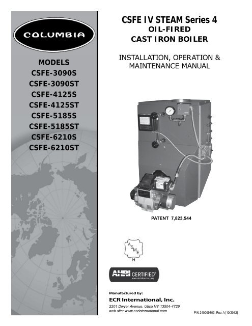
CSFE IV STEAM Series 4 - Columbia Heating
CSFE IV STEAM Series 4 - Columbia Heating
CSFE IV STEAM Series 4 - Columbia Heating

Create successful ePaper yourself
Turn your PDF publications into a flip-book with our unique Google optimized e-Paper software.
RATINGS, DATARATINGSWITHOUTTANKLESSBoiler ModelNumberWITHTANKLESSMin. Natural DraftOil Burner Input (1)Net AHRI Ratings (3) Chimney SizeCapacityMBH (4) Steam Sq. Ft.G.P.H. MBH (2) Round SquareMBH SteamA.F.U.E.Rating<strong>CSFE</strong> -3090 S <strong>CSFE</strong> -3090 ST 0.90 126 106 80 333 6 8"x8"x15' 82.0<strong>CSFE</strong> -4125 S <strong>CSFE</strong> -4125 ST 1.25 175 147 110 458 6 8"x8"x15' 82.0<strong>CSFE</strong> -5185 S <strong>CSFE</strong> -5185 ST 1.85 259 216 162 675 8 8"x8"x15' 82.0<strong>CSFE</strong> -6210 S <strong>CSFE</strong>-6210 ST 2.10 294 247 185 771 8 8"x8"x15' 82.0NOTES:(1)Burner input is based on an oil heating value of 140,000 Btu/gal.(2)MBH = 1000 Btu per hour [Btu = 15 Amps, 60 HzBoiler ModelNumberTANKLESS WATER HEATER CAPACITIESInputRateG.P.H.TanklessHeaterNumberTanklessHeater CapacityIntermittent DrawG.P.M.Boiler WaterContent(Gallons)To WaterLineToLWCOLine<strong>CSFE</strong>-3090 ST 0.90 L-24 2 11 8<strong>CSFE</strong> -4125 ST 1.25 L-24 4½ 13 9<strong>CSFE</strong> -5185 ST 1.85 L-24 4½ 15 10<strong>CSFE</strong> -6210 ST 2.10 L-24 4½ 17 113
TABLE OF CONTENTSDimensions ........................................................2Ratings, Data .....................................................3Safety Symbols ..................................................4Locating The Boiler .............................................5Ventilation And Combustion Air ............................6Supply And Return Piping ....................................8Venting System Inspection & Installation .............12Oil Tank And Piping ...........................................13Electrical Wiring ...............................................14Operating Instructions .......................................16Maintenance Procedures ....................................19Service Checklist ..............................................21IMPORTANT: Read and understand the followinginstructions COMPLETELY before installing.! WARNINGInstallations of boilers and venting shall be doneonly by qualified expert and in accordance with thismanual. Installing or venting a boiler or any othergas appliance with improper methods or materialscould result in serious injury or death due to fireor to asphyxiation from poisonous gases such ascarbon monoxide which is odorless and invisible.! WARNINGKeep boiler area clear and free from combustiblematerials, gasoline and other flammable vapors andliquids.Do not obstruct air openings to boiler room.KEEP THIS MANUAL NEAR BOILERRETAIN FOR FUTURE REFERENCESAFETY SYMBOLSThe following defined symbols are used throughout thismanual to notify reader of potential hazards of varying risklevels.! DANGERIndicates a hazardous situation which, if notavoided, WILL result in death or serious injury.Modification, substitution or elimination of factoryequipped, supplied or specified components couldresult in personal injury or the loss of life.Owner - Installation and service of this boiler mustbe performed by a qualified installer.Installer - Leave all instructions with the boiler forfuture reference.When this product is installed in the Commonwealthof Massachusetts the installation must be performedby a Licensed Plumber or Licensed Gas Fitter.!WARNINGIndicates a hazardous situation which, if not avoided,could result in death or serious injury.!CAUTIONIndicates a hazardous situation which, if notavoided, could result in minor or moderate injury.NOTICEIndicates information which should be followed toensure proper installation and operation.PATENT 7,823,5444
LOCATING THE BOILER• Installations shall conform to the requirements ofthe authority having jurisdiction. Such applicablerequirements take precedence over the generalinstructions of this manual.• Where required by the authority having jurisdiction,the installation must conform to the American Societyof Mechanical Engineers Safety Code for Controls andSafety Devices for Automatically Fired Boilers, ANSI/ASME No. CSD-1.!WARNINGFire hazard. Do not install boiler on combustibleflooring or carpeting. Failure to follow theseinstructions could result in death or serious injury.FOR INSTALLATION ON NON-COMBUSTIBLE FLOORS ONLYBoiler must not be installed on carpeting or vinyl flooring.Minimum clearances to combustible construction are:• Locate boiler in front of final position before removingcrate.• Provide level solid base as near chimney as possibleand centrally located with respect to heat distributionsystem as practical.• Allow 24 inches in front, top and right hand side forservicing and cleaning, or removing tankless waterheating coil.TOPFRONTFLUE CONNECTORREARLEFT SIDERIGHT SIDE24 IN.24 IN.9 IN.24 IN.6 IN.24IN.• Recommend 24 inches be allowed in back of boiler forconvenience when skimming hole is used.• When installed in a utility room, the door should bewide enough to allow largest boiler part to enter, or topermit replacement of another appliance such as waterheater.• Install boiler such that oil ignition system componentsare protected from water (dripping, spraying, rain etc.)during appliance operation and service.NOTE: Clearance for access should exceed fire protectionclearance.Figure #2 - Minimum Clearances To CombustibleConstruction (as seen from above)BACK24"6" BOILER 24"24"FRONT5
Input (Mbh)!WARNINGAsphyxiation, fire hazard. Do not obstruct airopenings to combustion area. Follow instructionsbelow, to maintain adequate combustion air.COMBUSTION AIR REQUIREMENTS(Minimum Opening Requirement)Unconfined Area*Confined Area**Outside Inside Outside Combustion AirCombustion Air1 Sq.In./5000 BTU/Hr(Step 4)VENTILATION AND COMBUSTION AIRCombustion Air1 Sq. In./1000 BTU/Hr (Min. 100 Sq. In.)(Figure #1)Vertical Ducts Horizontal Ducts1 Sq. In./4000 BTU/Hr 1 Sq. In./2000 BTU/Hr(Figures # 2 & #3) (Figure # 4)126 26 126 32 63175 35 175 44 88259 52 259 65 130294 59 294 74 147* A space whose volume is not less than 50 cubic feet per 1000 BTU/Hour of all appliances installed in that space (cubic feet ofspace = height x width x length)** A space whose volume is less than 50 cubic feet per 1000 BTU/Hour of all appliances installed in that space (cubic feet of space= height x width x length)1. Ventilation of boiler room must be adequate enough toprovide sufficient air to properly support combustion,venting and maintain safe ambient temperatures undernormal operating conditions.2. When the boiler is located in an unconfined space in abuilding of conventional construction frame, masonryor metal, infiltration normally is adequate to provideair for combustion and ventilation. However, in anybuilding which has been altered to conserve energyor to minimize infiltration, the boiler area shouldbe considered as a confined space. If there is anydoubt, install air supply provisions for combustionand ventilation in accordance with Chapter 5, Air forCombustion and Ventilation, of NFPA 31, Standardfor the Installation of Oil Burning Equipment. Therecommendations that follow, or applicable provisionsof the local building codes.3. When the boiler is installed in an unconfined space,in a building of unusually tight construction, air forcombustion and room ventilation must be obtainedfrom outdoors or from spaces freely communicatingwith the outdoors. A permanent opening or openingshaving a total free area of not less than 1 square inchper 5,000 BTU per hour of total input rating of allappliances shall be provided. Ducts may be used toconvey make-up air from the outdoors and shall havethe same cross-sectional area of the openings to whichthey are connected.4. When air for combustion and room ventilation is frominside buildings, the confined space shall be providedwith two permanent openings, one starting 12 inchesfrom the top and one 12 inches from the bottom of theenclosed space. Each opening shall have a minimumfree area of 1 square inch per 1,000 BTU per hour ofthe total input rating of all appliances in the enclosedspace, but must not be less than 100 square inches.These openings must freely communicate with theinterior areas having adequate infiltration from theoutside. See Figure #3.Figure #3CHIMNEYORL TYPE VENT PIPEBASEBOARDVENT PIPE12"VENTS12"6
VENTILATION AND COMBUSTION AIR5. When the boiler is installed in a confined space andall air is provided from the outdoors, the confinedspace shall be provided with two permanent openings,one commencing within 12 inches from the top andone commencing 12 inches from the bottom of theenclosure. The openings shall communicate directly, orby ducts, with the outdoors or spaces (crawl or attic)that freely communicate with the outdoors. One of thefollowing methods must be used to provide adequateair for ventilation and combustion.A. When directly communicating with the outdoors,each opening shall have a minimum free area of 1square inch per 4,000 BTU per hour of total inputrating of all equipment in the enclosure. (Figure#4)B. When communicating with the outdoors by meansof vertical ducts, each opening shall have aminimum free area 1 square inch per 4,000 BTUper hour of total input rating of all appliances in theenclosed space. (Figure #5)C. If horizontal ducts are used, each opening shallhave a minimum free area 1 square inch per 2,000BTU per hour total input rating of all appliances inthe enclosed space. (Figure #6)D. When ducts are used, they shall be of the samecross sectional area as the free area of the area ofthe openings to which they connect. The minimumdimension of rectangular air ducts shall not be lessthan 3 inches.6. In calculating free area using louvers, grills or screensfor the above, consideration shall be given to theirblocking effect. Screens used shall not be smaller than1/4 inch mesh. If the free area through a design oflouver or grill is known, it should be used in calculatingthe size opening required to provide the free areaspecified. If the design and free area is not known, itmay be assumed that wood louvers will have 20-25%free area and metal louvers and grills will have 60-75%free area. Louvers and grills shall be fixed in the openposition or interlocked with the boiler so that they areopened automatically during boiler operation.Figure #4Figure #5Figure #67
SUPPLY AND RETURN PIPING!WARNINGBurn or Scald Hazard. Discharge line shall be installed to safety valve outlet connection to avoid burns,scalding, or water damage due to discharge of steam and/or hot water during operation.Discharge line shall:• Connect to safety valve outlet. Piped down to safe point of disposal. Check local codes for maximumdistance from floor or allowable safe point of discharge.• Pipe size be of equal to or greater than of safety valve outlet over entire length of discharge line.• Have no intervening shutoff valve between safety valve and discharge to atmosphere. Do not plug orplace any obstruction in discharge line.• Terminate freely to atmosphere where any discharge will be clearly visible and at no risk of freezing.• Allow complete drainage of valve and discharge line.• Install safety valve with spindle in vertical position.• Do not install shutoff valve between boiler and safety valve.• Support safety valve discharge piping.• Be short and straight as possible.• Terminate with plain end, not threaded.• Constructed of material suitable for exposure to temperatures of 375° F (191°C); or greater.Refer to local codes and appropriate ASME Boiler and Pressure Vessel Code for additional installationrequirements.Figure 4 - Safety ValveSAFETY VALVEDISCHARGEPIPINGCheck local codesfor maximumdistance fromfloor or otherallowable safepoint of discharge6" Above Floor8
1. Suggested piping for steam heating system can beseen in Figure #7. Actual piping may vary based onsystem design and local conditions.SUPPLY AND RETURN PIPINGFigure #79
SUPPLY AND RETURN PIPING2. See Figure #8 for typical piping for domestic hot waterheater.• Automatic mixing valve must be installed on tanklessheater outlet. Install per valve manufacturer'sinstructions.• Install adjustable flow restrictor in cold water inletdue to varying water conditions.3. See Figures #9 and #10 for the suggested piping fora modular steam boiler.! DANGERWater temperatures exceeding 125°F will causesevere burns instantly or death by scalding.Figure #8PIPING FOR BUILT-INDOMESTIC HOT WATER HEATERUNTEMPEREDHOT WATERUNTEMPERED HOT WATER TOAUTOMATIC WASHERTEMPERING VALVEINSTALLED BELOW CENTERLINE OF BOILER HOTCONNECTIONFLOWCONTROLREGULATORDOMESTICHOT WATERT & P VALVECOLD WATERCOLD WATER IN10
RETURNSUPPLY AND RETURN PIPINGFigure #9SUGGESTED PIPING FOR MODULAR <strong>STEAM</strong> BOILERS - PUMPED RETURNSTOPVALVE<strong>STEAM</strong> MAINF & T TRAP HIGHLEVEL "SPILL"(DO NOT USE WITHCONDENSATE PUMP)TOSYSTEMTRAPCHECKVALVEFROMRECE<strong>IV</strong>ERTANKTORECE<strong>IV</strong>ERTANKSOLENOIDVALVE(OPTIONAL)STOPVALVEBLOWOFFVALVETORECE<strong>IV</strong>ERTANKFROMRECE<strong>IV</strong>ERTANKFigure #10SUGGESTED PIPING FOR MODULAR <strong>STEAM</strong> BOILERS - GRAVITY RETURNSTOPVALVE<strong>STEAM</strong> MAIN2"TOSYSTEMCHECKVALVE(OPTIONAL)STOPVALVE28"WATERLINEBLOWOFFVALVE11
VENTING SYSTEM INSPECTION & INSTALLATION!WARNINGBoiler is to be vented by natural draft and shall notbe connected into any portion of mechanical draftoperating system under positive pressure.• Inspect chimney to make certain it is constructedaccording to the latest revision of the NFPA 211. Localregulations may differ from this code and should bechecked. Where there is a conflict, the local code willprevail.If oil fired water heater is vented into same flue as boiler,provide separate hole into chimney whenever possible.When this isn’t possible, use “Y” connection in flue pipe,using separate draft regulator for each unit.When chimney does not provide adequate draft to handleinput from water heater and boiler simultaneously, wireunits so only one will operate at a time, favoring waterheater.• Install boiler into chimney having a masonry or metallicchimney liner.• Unlined chimney will have leaks that will cause poorchimney performance (no draft), and could result inpositive pressure in the combustion chamber.• Horizontal portions of venting system should notexceed 10 feet in length. Horizontal lengths over 10 ft.will have a negative effect on chimney performance.• Extend chimney at least 2 ft. above any portion ofbuilding within 10 ft. Producing a -.02 inch W.C. draftin the combustion chamber. See Figure #11.• See Ratings Table page 3 for recommended minimumchimney or vent sizes.• Inadequate draft causes improper combustion,resulting in dirty flue ways and high fuel bills.• Connect flue pipe same size as boiler outlet to chimney,sloping upward continuously toward the chimneyapproximately ¼" per foot. Bolt or screw jointstogether to avoid sag.Figure #11RIDGE2’ (.61 M) MIN.MORE THAN 10’ (3.1 M)10’ (3.1 M)HEIGHT ABOVE ANYROOF SURFACE WITHIN10’ (3.1 M)HORIZONTALLYCHIMNEY 3’ (.92 M)GAS VENT ORTYPE L VENT2’ (.61 M) MIN.12
OIL TANK AND PIPINGTank Installation• Install oil tank and piping in accordance with NationalBoard of Fire Underwriters and local regulations.• Oil storage tank, vent, fill pipe and caps should be asprescribed by local codes.• In no case should vent pipe be smaller than 1¼" I.P.S.Fill pipe should not be less than 2" I.P.S.Suction Line Installation• Suction line from tank to burner should be onecontinuous piece of tubing to prevent air entering line.• Suction line, must be ⅜" O.D. copper tubing for runs of50 feet or less, and ½" O.D. for longer runs.Oil Line Installation• Oil return line, same size as suction line, must be usedon any installation where bottom of tank is below fuelunit of burner.• Bury oil lines or protect from mechanical injury.• Flare fittings on all oil lines are recommended.Compression fittings on suction line often allow air tobe drawn into fuel pump, making it difficult to maintainoil pressure at nozzle.• Do not run overhead fuel lines from tank to oil burner.Fuel Pump Connections• Fuel pump connections and by-pass should be madeaccording to instructions attached to fuel pump.• If tank is more than 20' from boiler, install two stagefuel unit in place of single stage pump supplied asstandard equipment with burner.• Verify rotation and speed are the same and pump issuitable for burner horsepower rating.Install oil line filter and shut-off valve in the suction line.Install shut-off valves in both suction and return lines atthe burner for convenience in servicing burner.Allow extra tubing at burner so burner may be removedfrom boiler for cleaning without disconnecting tubing. Anoptional flexible oil line is available. See Figures #12 -#13.Figure #12 Typical Installation Single Pipe OilSystemFigure #13 Typical Installation Two Pipe Oil System13
ELECTRICAL WIRING!WARNINGElectrical shock hazard. Turn OFF electrical power supplyat service panel before making electrical connections.Failure to do so could result in death or serious injury.Electrical wiring must conform with the latest revisions ofthe National Electrical Code, ANSI/NFPA No. 70, and/orlocal authority having jurisdiction.1. When an external electrical source is utilized, theboiler, when installed, MUST BE electrically groundedin accordance with these requirements.2. Install a fused disconnect switch between boiler andmeter at a convenient location.3. When the boiler is equipped with self-energizedcontrols, no outside source of electric power shall beconnected to the circuit of this system. (See "SteamWiring" on next page.)Thermostat Installation1. Thermostat should be installed on inside wall aboutfour feet above floor.2. NEVER install thermostat on outside wall.3. Do not install thermostat where it will be affected bydrafts, hot or cold pipes, sunlight, lighting fixtures,television, fireplaces, or chimneys.4. Check thermostat operation by raising and loweringthermostat as required to start and stop burner.5. Instructions for final adjustment of thermostatare packaged with thermostat (adjusting heatinganticipator, calibration, etc.).14
ELECTRICAL WIRING<strong>STEAM</strong> WIRING W/BECKETT BURNERCOMPONENT CODINGTH-1 Thermostat (Millivolt) MR-PS Manual Reset Pressure Switch CIR CirculatorTH-2 Thermostat (24 Volt) Control Terminal ECO Energy Cut-OffTH-3 Thermostat (Line Voltage) 1K Relay Coil PSC Pilot Safety CoilTR-1 Transformer (120V/24V/40VA) 1K1 Relay Contacts Wire ConnectionTR-2 Transformer (120V/24V/50VA) 1K2 Relay Contacts LWCO Low Water Cut OffLGV24 Volt Gas Valve LS Limit Switch EWF Electric Water FeederPS Pressure Switch MS Manual Switch PG Power GeneratorWIRING CODELine Voltage By FactoryLow Voltage By FactoryLine Voltage By InstallerLow Voltage By InstallerNOTE: Not all components listed are used in all control systems.15
HOTOPERATING INSTRUCTIONSSequence Of OperationOn call for heat, thermostat will actuate, completing thecircuit to the boiler. In turn, the ignition systems areactivated and ignition will begin.Figure #14ELECTRONIC LOWWATER CUT OFFPRESSURE RELIEFVALVETOP JACKETPANELIn event of a low water condition, an automatic low watercut-off device will interrupt power between the low watercut-off and burner. Burner remains off until low watercondition is corrected, (i.e., manually restore boiler wateror utilize water feeder device which automatically restoreswater to its normal operating level).Installer - Before putting boiler in operation, testmechanical low water cut-off device for proper operation.While burner is on, open blow-off valve located in lowerportion of cut-off body. This will drain water quickly fromcut-off body and break circuit to burner. If it does not,replace control.! DANGERWater temperatures exceeding 125°F will causesevere burns instantly or death by scalding.28"1/4" SLOTWATERLINEINSPECTIONCOVERLOWER FRONTJACKET PANELBURNERELECTRICALDISCONNECTMOUNTINGSCREWS(BOTH SIDES)Refill boiler to its normal water line.Operating Instructions• Start of heating season have venting system inspected.Check vent pipe from boiler to chimney for signsof deterioration by rust or sagging joints. Repair ifnecessary.• Remove vent pipe at base of chimney or flue and, usingmirror, check for obstruction and verify compliance tolatest revision of the NFPA 211.• Operate lever of safety valve on boiler periodically toverify it is functioning properly. See Figure #14.• Safety relief valve should open before steam pressureexceeds 15 psi. reading on the gauge. If this pressureis exceeded and safety relief valve leaks steam whenboiler is operating at normal pressures, immediatelyreplace. Corrosion can build up rapidly at valve seatand prevent its functioning as a safety device.16
OPERATING INSTRUCTIONSStart-Up And Adjustment Of Oil Burner(See oil burner instructions for nozzle and electrode setting)Do not set fire visually.Instruments are only reliable method to determine properair adjustments.Improperly adjusted burner causes soot and high fuel billsbecause of incomplete combustion of the fuel oil. This maythen require excessive boiler maintenance, service costs,and in some instances, house cleaning or redecorating.Consult a qualified service mechanic to make properadjustments with smoke tester, CO 2indicator, and draftgauge. Bacharach or Dwyer test kits include theseinstruments.1. Check oil burner nozzle to verify it is tight in adapter.Burner mounting bolts should be tight.2. Check electrode setting, they may have been jarred outof position during transportation.3. Lubricate burner motor if necessary.4. Set room thermostat to call for heat, or jumpthermostat contacts on boiler control.5. Open all oil line valves.6. Turn service switch on. Burner should start.7. On one pipe fuel systems only, bleed pump as soon asburner starts. Allow oil to run until all traces of air insuction line disappear.8. Turn “OFF” burner and install pressure gauge port onpump.9. Start burner again and check oil pressure for 140 lbs.Adjust if necessary.BOILERNO.HEADTYPEHEADSETTINGBECKETT AFG SETTINGSSTATICPLATENOZZLEPUMPPRESSURE[PSI]AIRBANDAIRSHUTTER<strong>CSFE</strong> -3090 L1 -- 3⅜ 0.75-60°B 150 1 3<strong>CSFE</strong> -4125 V1 0 2¾ 1.10-60°B 140 1 8<strong>CSFE</strong> -5185 F12 -- 2¾ 1.50-70°B 150 2 10<strong>CSFE</strong> -6210 F16 -- -- 1.75-70°B 145 2 10* Boiler model number on rating plate includes suffix 'S' or 'ST'.IMPORTANT: Check safety control circuit after burner adjustments have been made for satisfactory performance.17
MAINTENANCE PROCEDURES! WARNINGBurn and scald hazard. Verify Boiler is off andcooled before performing maintenance. Have aqualified service agent perform maintenance. Failureto follow these instructions could result in death orserious injury.Before seasonal start up it is advisable to have a qualifiedservice agency check boiler for soot and scale in flues,change oil filter and nozzle, clean burner and re-adjustburner input rate to maintain proper operation and highoperating efficiency.On steam boilers verify boiler is filled to water line asindicated in Figure #14. Gauge valves should be normallyopen. To remove dirt from gauge glass petcock may beopened to flush out the glass.Radiator valves on one-pipe steam system must be eitherwide open or tightly shut. Do not attempt to regulate roomtemperature by partially closing the radiator valve.Air vents on steam radiators and the supply main releaseair from the system. If radiators do not heat satisfactorily,make sure the air vents are clean and operational.The lever of the pressure relief valve on the boiler (Figure#14) should be operated periodically to make sure that itis functioning properly.Safety valve should open before the steam pressureexceeds the 15 psi. reading on the gauge. (Figure #14)If this pressure is exceeded and the safety valve does notopen, it must be replaced. If the safety valve leaks steamwhen the boiler is operating at normal pressures, it shouldbe immediately replaced. Corrosion can build up rapidlyat the valve seat and prevent its functioning as a safetydevice.If the water in a steam boiler appears to be dirty or oily, orthe water level in the gauge glass fluctuates considerably,the boiler should be cleaned. A competent service personwill use approved cleaning compounds and properly cleanand flush out the boiler. He/she should also clean or replaceair vents and traps, clean flue passages and check forproper operation of all controls and safety devices.The venting system should be inspected at the start of eachheating season. Check the vent pipe from the boiler to thechimney for signs of deterioration by rust or sagging joints.Repair if necessary.Impurities in boiler water of a steam boiler may causefoaming and an unsteady water line, or prevent steamgeneration. They may result in objectionable odorsescaping from the vents on water boilers. This conditionis caused by oil, grease, and sediment from pipe fittingscollecting within the boiler and can be remedied only bygiving the boiler a thorough cleaning.BOILERS SHOULD BE CLEANED BY SKIMMING ORBLOWING DOWN.NOTICEDo not leave Boiler unattended during cleaning/skimming process.Skimming Off ImpuritiesSome of the impurities in the boiler water will float on thewater and must be skimmed off.With the boiler empty and cool, slowly begin to add water.After water has entered boiler - never before - turn “on”oil burner and adjust water flow so that the water beingadded is kept just below boiling point. Avoid boiling andturbulence.Gradually raise hot water level to skimming hole (Figure #7)installed on the rear section of the boiler being careful not toraise it above the opening of the hole. Skim until there are noimpurities. Repeat the process if necessary.Water may be checked to make sure it is free from oil bydrawing off a sample at the skimming hole. If the sampleis reasonably free from oil, it will not froth when boiled onstove. This test does not indicate the amount of sedimentwhich may lay in the bottom of the boiler. It is thereforenecessary that the boiler be further cleaned by “blowingdown.”Blowing Down The BoilerBefore blowing down the boiler, fill it to the water line.Turn on burner and allow five pounds of steam pressure tobuild up. Run a temporary connection from one of the drainvalves to a nearby sewer. Connect to a drain valve on theopposite end of the boiler from feed water inlet, if possible.Shut off the oil burner, open drain valve and blow down theentire contents of boiler.Allow boiler to thoroughly cool and slowly refill to waterline. Repeat as many times as required until blow off wateris clear. Owner should blow down boiler at least once eachmonth of the heating season.19
MAINTENANCE PROCEDURESUsing Cleaning CompoundIf an exceptional amount of dirt or sludge seems to bepresent in the boiler, a boiler cleaning compound made bya reputable manufacturer may be used according to theinstructions of the manufacturer of the compound. Whenany type of cleaning compound is used, care must be takento thoroughly flush all traces of the compound out of theboiler.Following blow down allow the boiler to cool. Add freshwater slowly. Be certain to blow enough times as requiredto remove compounds from system.The area around the boiler must be kept clear and freeof combustible materials, gasoline and other flammablevapors and liquids.The free flow of combustion and ventilation air to the boilerand boiler room must not be restricted or blocked.Periodic inspection and tightening of the tankless heater/cover plate bolts will reduce the risk of leaks. See parts 3 and5 under "Coil and Cover Plate Replacement Parts."Electronic Low Water Cut-OffOperation of the probe and control should be checked, withthe burner on, by draining the water via the drain on thebottom of the boiler. This will drain the water quickly fromthe boiler and break the circuit to the burner. If it does notinspect the probe for scaling. If scaling is present, clean offthe probe, refill the boiler until the ELWCO is satisfied, andperform the check again.It is suggested that a qualified service agency be employedto make an annual inspection of the boiler and heatingsystem. They are experienced in making the inspectionsoutlined above and, in the event repairs or corrections arenecessary, can make the proper changes for safe operationof the boiler.20
SERVICE CHECKLISTInspect Chimney and Flue Pipe [ X ]Inspect and Clean Appliance [ X ]Inspect Oil Line - Size/Leaks [ X ]Inspect Electrical Connections [ X ]Install New Filter [ X ]Room Make-up Air [ X ]Electrode Setting [ X ]Proper Light-Off (Hot & Cold) [ X ]Controls and Safety Devices [ X ]Nozzle-Size, Angle, Type [ * ]Pump Pressure/Vacuum [ * ]Line Voltage/Motor Amps [ * ]Smoke Test [ * ]Draft-Overfi re/In Flue [ * ]CO 2or O 2[ * ]Flue Gas Temperature [ * ]* Measure with instruments and record results below.DateSERVICE RECORDNozzle Pump Pressure Line MotorDraft CO 2Smoke#Size Angle Type PSI Voltage AmpsO.F. INF or O 2FlueTemp °F21
NOTES
<strong>Columbia</strong>P.O. Box 24202,Baltimore, Maryland 21227