MAGB SERIES Gas Fired Modu-Pac Multiple ... - Columbia Heating
MAGB SERIES Gas Fired Modu-Pac Multiple ... - Columbia Heating
MAGB SERIES Gas Fired Modu-Pac Multiple ... - Columbia Heating
Create successful ePaper yourself
Turn your PDF publications into a flip-book with our unique Google optimized e-Paper software.
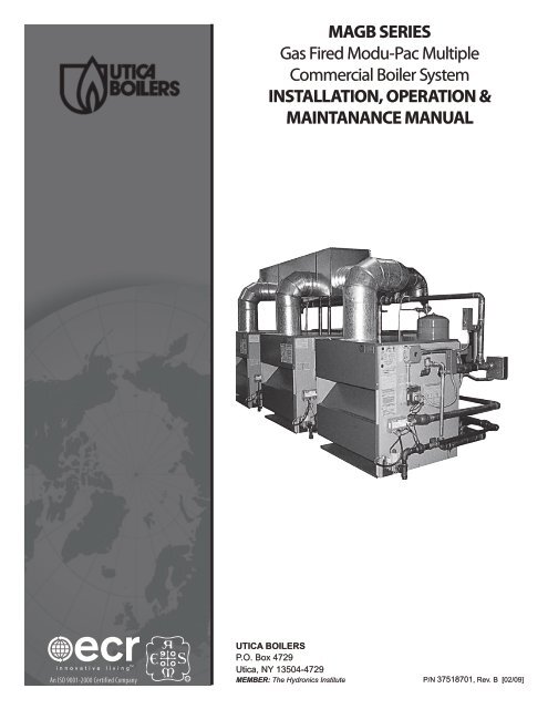
<strong>MAGB</strong> <strong>SERIES</strong><strong>Gas</strong> <strong>Fired</strong> <strong>Modu</strong>-<strong>Pac</strong> <strong>Multiple</strong>Commercial Boiler SystemINSTALLATION, OPERATION &MAINTANANCE MANUALAn ISO 9001-2000 Certified CompanyRUtica BOILERSP.O. Box 4729Utica, NY 13504-4729MEMBER: The Hydronics InstituteP/N 37518701, Rev. B [02/09]
<strong>MAGB</strong> <strong>SERIES</strong> GAS FIRED BOILERS FOR FORCED HOT WATERInstallation Manual and Operating InstructionsTABLE OF CONTENTSBoiler Ratings & Capacities.......................................2Typical Layouts For <strong>Gas</strong> <strong>Fired</strong> Systems....................4Supply And Return Piping........................................5Installation Procedure..............................................5Ventilation And Combustion Air.............................6Vent Installation........................................................8Vent System Modification.........................................9Connecting Boilers With Refrigeration Systems....10Connecting <strong>Gas</strong> Service.......................................... 11Electrical Wiring...................................................... 12Lighting Instructions.............................................. 14Normal Sequence of Operation............................. 15General Instructions............................................... 16Checking <strong>Gas</strong> Input Rates To Boiler...................... 18Optional Controls & Wiring.................................... 18<strong>MAGB</strong> Series Replacement Parts........................... 20SAFETY SYMBOLSThe following defined symbols are used throughout thismanual to notify the reader of potential hazards of varyingrisk levels.!!!DANGERIndicates an imminently hazardous situation which, if notavoided, WILL result in death, serious injury or substantialproperty damage.WARNINGIndicates an imminently hazardous situation which, if notavoided, MAY result in death, serious injury or substantialproperty damage.CAUTIONIndicates an imminently hazardous situation which, if notavoided, may result in injury or property damage.KEEP THIS MANUAL NEAR BOILER AND RETAIN FORREFERENCE.NOTICERead the following instructions COMPLETELY beforeinstalling!2. To the owner: Installation and service of this boiler mustbe performed by a qualified installer.3. To the installer: Leave all instructions with the boiler forfuture reference.H2
Boiler Ratings & Capacities!WARNINGAll installations of boilers and venting should be done only by a qualified expert and in accordance with the appropriate manual.Installing or venting a boiler or any other gas appliance with improper methods or materials may result in serious injury or deathdue to fire or to asphyxiation from poisonous gases such as carbon monoxide which is odorless and invisible.BOILER dimensionsMODELNUMBER<strong>MAGB</strong> GAS FIRED BOILER <strong>SERIES</strong> engineering and DIMENSIONAL DATANUMBEROFMODULESSHIPPINGWEIGHT (LBS.)WATERCONTENT(GALLONS)Dimensions in InchesA B C<strong>MAGB</strong>500 2 945 17.6 62.250” 26.625” 13.313”<strong>MAGB</strong>600 2 1065 20.8 70.000” 30.500” 15.250”<strong>MAGB</strong>750 3 1400 26.4 97.875” 26.625” 13.313”<strong>MAGB</strong>900 3 1600 31.2 109.500” 30.500” 15.250”<strong>MAGB</strong>1000 4 1890 35.2 133.500” 26.625” 13.313”<strong>MAGB</strong>1200 4 2135 41.6 149.000” 30.500” 15.250”<strong>MAGB</strong>1500 5 2665 52.0 188.000” 30.500” 15.250”<strong>MAGB</strong>1800 6 3200 62.4 228.000” 30.500” 15.250”<strong>MAGB</strong>2100 7 3730 72.8 267.500” 30.500” 15.250”<strong>MAGB</strong>2400 8 4265 83.2 307.000” 30.500” 15.250”3
Typical Layouts For <strong>Gas</strong> <strong>Fired</strong> SystemsACCESS27"TYP31"MIN.ACCESS27"TYPREAR"L""D"LFRONT"D""L" FOR 1 BATTERY, (3 BOILERS PER BATTERY), IS99 ⅞" FOR <strong>MAGB</strong> 750 AND 111 ½" FOR <strong>MAGB</strong> 900"D" FOR 1 BATTERY, (3 BOILERS PER BATTERY), 1S36 ⅝" FOR <strong>MAGB</strong> 750 AND 40 ½" FOR <strong>MAGB</strong> 900"L" FOR 1 BATTERY, (2 BOILERS PER BATTERY), IS63 ¼" FOR <strong>MAGB</strong> 500 AND 71" FOR <strong>MAGB</strong> 60031" MIN."D" FOR 1 BATTERY, (2 BOILERS PER BATTERY), 1S36 ⅝" FOR <strong>MAGB</strong> 500 AND 40 ½" FOR <strong>MAGB</strong> 600"L" FOR 1 BATTERY, (5 BOILERS PER BATTERY)IS 192 ½" FOR <strong>MAGB</strong> 1500"D" FOR 1 BATTERY, (5 BOILERS PER BATTERY)IS 40 ½" FOR <strong>MAGB</strong> 1500ACCESS27"TYPACCESS27"TYPACCESS"E""D"*"L"FRONTFRONT**"L"*"L"* "L" FOR 1 BATTERY, (7 BOILERSPER BATTERY), IS 273 ½"** "L" FOR 1 BATTERY, (4 BOILERSPER BATTERY), IS 136 ½" FOR <strong>MAGB</strong> 1000AND 152" FOR <strong>MAGB</strong> 1200."D" FOR 1 BATTERY WITH 4 BOILERS IS 36 ⅝"FOR <strong>MAGB</strong> 1000 AND 40½" FOR <strong>MAGB</strong> 1200."E" FOR 1 BATTERY WITH 7 BOILERS IS 40½".FRONT**"L""D"ACCESS27"TYP* "L" FOR 1 BATTERY WITH 5 BOILERS IS 192 ½" FOR <strong>MAGB</strong> 1500** "L" FOR 1 BATTERY WITH 7 BOILERS IS 273 ½" FOR <strong>MAGB</strong> 2100"D" FOR 1 BATTERY WITH 7 BOILERS IS 40 ½".ACCESSACCESSNOTE: FOR ACCESS DIMENSION, REFER TO LOCAL CODES OR MAINTAINNO LESS THAN 24".5
Supply And Return Piping!WARNING1. Keep boiler area clear and free from combustible materials,gasoline and other flammable vapors and liquids.2. DO NOT obstruct air openings to the boiler room.3. Modification, substitution or elimination of factoryequipped, supplied or specified components may result inproperty damage, personal injury or the loss of life.4. When this product is installed in the Commonwealthof Massachusetts the installation must be performed by aLicensed Plumber or Licensed <strong>Gas</strong> Fitter.Improper installation, adjustment, alteration, service ormaintenance can cause injury or property damage.Installation Procedure61.2.3.4.5.The installation must conform to the requirements of theauthority having jurisdiction or, in the absence of such requirements,to the latest revision of the National Fuel <strong>Gas</strong> Code,ANSI Z223. (Available from the American <strong>Gas</strong> Association,8501 E. Pleasant Valley Road, Cleveland, Ohio 44134). Referenceshould also be made to local gas utility regulations andother codes in effect in the area in which the installation is to bemade.Where required by the authority having jurisdiction, theinstallation must conform to American Society of MechanicalEngineers Safety Code for Controls and Safety Devices ForAutomatically <strong>Fired</strong> Boilers, No.CSD-1.This boiler series is classified as a Category 1 and the ventinstallation shall be in accordance with the latest revision of theNational Fuel <strong>Gas</strong> Code noted above or applicable provisions ofthe local building codes.This boiler has met safe lighting and other performance criteriawith the gas manifold and control assembly on the boiler perthe latest revision of ANSI Z21.13.The boiler shall be installed such that the gas ignition systemcomponents are protected from water (dripping, spraying,rain, etc.) during appliance operation and service, (circulator
INSTALLATION PROCEDURE6.7.8.9.replacement, condensate trap, control replacement, etc.).LOCATE BOILER on level, solid base as near the chimney aspossible and centrally located with respect to the heat distributionsystem as practical.Allow 24 inches at the front and right side for servicing andcleaning.When installed in a utility room, the door should be wideenough to allow the largest boiler part to enter, or to permitreplacement of another appliance such as a water heater.The MEA number for this boiler series is 19-79-E.FOR INSTALLATION ON NON-COMBUSTIBLE FLOORS ONLY*. The boiler must not be installed on carpeting. Minimum clearancesto combustible construction are:TOP............................................18 IN.FRONT.................................ALCOVEFLUE CONNECTOR ...................6 IN.REAR...........................................4 IN.CONTROL SIDE..........................9 IN.OTHER SIDE ..............................3 IN.NOTE: Greater clearances for access should supersede fire protectionclearances.* For installation on combustible flooring special base part no. 325-2-8.00 must be used.Ventilation And Combustion Air!WARNINGAir openings to combustion area must not be obstructed.By following the chart below, adequate combustion air canbe maintained.ModelNumberNumberOf<strong>Modu</strong>lesCOMBUSTION AIR REQUIREMENTS(Minimum Opening In Square Inches)*UNCONFINED AREAOutsideCombustion Air 1Sq. In./4000 Btuh(See Figure #2)OutsideCombustion Air 1Sq. In./1000 Btuh(See Figure #1)**CONFINED AREAOUTSIDE COMBUSTION AIRVert. Ducts1 Sq. In./4000 BtuhHorz. Ducts1 Sq. In./2000 Btuh<strong>MAGB</strong>500 2 125 500 125 250<strong>MAGB</strong>600 2 150 600 150 300<strong>MAGB</strong>750 3 188 750 188 375<strong>MAGB</strong>900 3 225 900 225 450<strong>MAGB</strong>1000 4 250 1000 250 500<strong>MAGB</strong>1200 4 300 1200 300 600<strong>MAGB</strong>1500 5 375 1500 375 750<strong>MAGB</strong>1800 6 450 1800 450 900<strong>MAGB</strong>2100 7 525 2100 525 1050<strong>MAGB</strong>2400 8 600 2400 600 1200* Unconfined area: A space whose volume is not less than 50 cubic feet per 1000 Btu per hour of all appliancesinstalled in that space (Cubic feet of space = height x width x length).** Confined area: A space whose volume is less than 50 cubic feet per 1000 Btu per hour of all appliancesinstalled in that space (cubic feet of space = height x width x length).7
VENTILATION & COMBUSTION continuedFigure #1 Figure #21.2.3.4.5.Ventilation of the boiler room must be adequate to provide sufficientair to properly support combustion per the latest revisionof the National Fuel <strong>Gas</strong> Code, ANSI Z223.1.When a boiler is located in an unconfined space in a building orconventional construction frame, masonry or metal building,infiltration normally is adequate to provide air for combustionand ventilation. However, if the equipment is located in abuilding of tight construction (See the National Fuel <strong>Gas</strong> Code,ANSI Z223.1) the boiler area should be considered as a confinedspace. If there is any doubt, install air supply provisions in accordancewith the latest revision of the National Fuel <strong>Gas</strong> Code.When a boiler is installed in an unconfined space, in a buildingof tight construction, air for combustion and ventilation mustbe obtained from outdoors or from spaces freely communicatingwith the outdoors. A permanent opening or openings havinga total free area of not less than 1 square inch per 5,000 BTUper hour of total input rating of all appliances shall be provided.Ducts may be used to convey makeup air from the outdoorsand shall have the same cross-sectional area of the openings towhich they are connected.When air for combustion and ventilation is from inside buildings,the confined space shall be provided with two permanentopenings, one starting 12 inches from the top and one 12 inchesfrom the bottom of the enclosed space. Each opening shallhave a minimum free area of 1 square inch per one thousand(1000) BTU per hour of the total input rating of all appliancesin the enclosed space, but must not be less than one hundred(100) square inches. These openings must freely communicatedirectly with other spaces of sufficient volume so that the combinedvolume of all spaces meets the criteria for an unconfinedspace. See figure #1.When the boiler is installed in a confined space and all airis provided from the outdoors the confined space shall beprovided with one or two permanent openings according to8methods A or B. When ducts are used, they shall be of the samecross sectional area as the free area of the area of the openingsto which they connect. The minimum dimension of rectangularair ducts shall be not less than 3 x 3 inches or 9 square inches.A. When installing two openings, one must commence within12 inches from the top and the other within 12 inches fromthe bottom of the enclosure. The openings shall communicatedirectly, or by ducts, with the outdoors or spaces(crawl or attic) that freely communicate with the outdoors.One of the following methods must be used to provideadequate air for ventilation and combustion.I. When directly communicating with the outdoors, eachopening shall have a minimum free area of 1 square inchper 4,000 BTU per hour of total input rating of all equipmentin the enclosure. See figure #2.II. When communicating with the outdoors by means of verticalducts, each opening shall have a minimum free area 1square inch per 4,000 BTU per hour of total input rating ofall appliances in the enclosed space.III. If horizontal ducts are used, each opening and duct shallhave a minimum free area 1 square inch per 2,000 BTU perhour of total input rating of all appliances in the enclosedspace.B. One permanent opening, commencing within 12 inchesof the top of the enclosure, shall be permitted where theequipment has clearances of at least 1 inch from the sides,1 inch from the back, and 6 inches from the front of theboiler. The opening shall directly communicate withthe outdoors or shall communicate through a vertical orhorizontal duct to the outdoors or spaces (crawl or attic)that freely communicate with the outdoors. The openingsmust have a minimum free area of 1 square inch per3000 Btu per hour of the total input rating of all equipmentlocated in the enclosure. The free area must be no less than
6.the sum of the areas of all vent connectors in the confinedspace.In calculating free area using louvers, grilles or screens for theabove, consideration shall be given to their blocking effect.Screens used shall not be smaller than ¼ inch mesh. If the freearea through a design of louver or grill is known, it should beused in calculating the size opening required to provide the freearea specified. If the design and free area is not known, it mayVENTILATION & COMBUSTION continuedbe assumed that wood louvers will have 20-25% free area andmetal louvers and grilles will have 60-75% free area. Louversand grilles should be fixed in the open position or interlockedwith the boiler so they are opened automatically during theboiler operation.Vent Installation!WARNINGThis boiler is to be vented by natural draft and shall not beconnected to the mechanical draft system operating underpositive pressure.1.2.3.4.5.The vent pipe must slope upward from the boiler not less then¼ inch for every 1 foot to the vent terminal.Horizontal portions of the venting system shall be supportedrigidly every 5 feet and at the elbows. No portion of the ventpipe should have any dips or sags.This boiler series is classified as a Category 1 and the vent installationshall be in accordance with the National Fuel <strong>Gas</strong> Codenoted above or applicable provisions of the local building codes.Inspect chimney to make certain it is constructed according toNFPA 211. The vent or vent collector shall be Type B or metalpipe having resistance to heat and corrosion not less than thatof galvanized sheet steel or aluminum not less than 0.016 inchthick (No. 28 Ga).Connect flue pipe from draft hood to chimney. Bolt or screwjoints together to avoid sags. Flue pipe should not extend beyondinside wall of chimney. Do not install manual damper influe pipe or reduce size of flue outlet except as provided by thelatest revision of ANSI Z223.1. Protect combustible ceiling andwalls near flue pip with fireproof insulation. Where two or moreappliances vent into a common flue, the area of the commonflue must be at least equal to the area of the largest flue plus 50percent of the area of each additional flue.INSTALLATION FOR OPTIONAL VENT DAMPERNOTE: Refer to Figure #3 for steps 1 - 7.1. Place Vent Damper on or as close to vent outlet of boiler aspossible.2. Remove Vent Damper Motor cover.3. Feed Damper and Damper wire harness connectors throughbracket hole on Damper Motor frame.4. Tighten locknut onto Damper wire harness connector.5. Plug Damper connector into socket on Damper Motor frame.6. Replace Damper Motor cover.7. Wire Damper in accordance with figure #3.INSTRUCTIONS1. Ensure that only the boiler is serviced by the Vent Damper. SeeFigure #4.2. Clearance of not less than 6 inches between Vent Damper andcombustible material must be maintained. Additional clearanceshould be allowed for service of Vent Damper.3. Vent Damper must be in the open position when appliancemain burners are operating.4. The Vent Damper position indicator must be in a visible locationfollowing installation.5. The thermostat's heat anticipator must be adjusted to match thetotal current draw of all controls associated with the boiler duringa heating cycle.9
Vent InstallationLOCKNUTFigure #3 Figure #4HARNESSCONN.INSTALLERHOOK-UPDAMPERMOTORACCEPTABLE VENTDAMPER LOCATIONSREFER TO DAMPER MANUFACTURER'SINSTALLATION INSTRUCTIONS FORPOSITION OF DAMPER CONTROL BOXCHIMNEYVENTDAMPERDAMPERCONN.INSTALLERHOOK-UPXUN-ACCEPTABLEDAMPER LOCATIONSXXXVENTOUTLETBOILERSHOT WATER HEATERWhen an existing boiler is removed from a commonventing system, the common venting system is likelyto be too large for the proper venting of the appliancesremained connected to it. If this situation occurs, the followingtest procedure must be followed:REMOVAL OF BOILER FROM VENTING SYSTEMAt the time of removal of an existing boiler, the followingsteps shall be followed with each appliance remainingconnected to the common venting system placed inoperation, while the other appliances remaining connectedto the common venting system are not in operation.1. Seal an unused opening in the common venting system.2.3.Visually inspect the venting system for proper size and horizontalpitch and determine there is no blockage or restriction,leakage, corrosion and other deficiencies which could cause anunsafe condition.Insofar as is practical, close all building doors and windows andall doors between the space in which the appliances remainingconnected to the common venting system are located and otherspaces of the building. Turn on clothes dryers and any other ap-Vent System Modificationpliance not connected to the common venting system. Turn onany exhaust fans, such as range hoods and bathroom exhausts,so they operate at maximum speed. Do not operate a summerexhaust fan. Close fireplace dampers.4. Place in operation the appliance being inspected. Follow thelighting instructions. Adjust thermostat so appliance will operatecontinuously.5. Test for spillage at the draft hood relief opening after 5 minutesof main burner operation. Use the flame of a match or candle,or smoke from a cigarette, cigar or pipe.106.7.After it has been determined that each appliance remainingconnected to a common venting system properly vents whentested as outlined above, return doors, windows, exhaust fans,fireplace dampers and any other gas burning appliances to theirprevious condition of use.Any improper operation of the common venting system shouldbe corrected so the installation conforms with the latest revisionof the National Fuel <strong>Gas</strong> Code, ANSI Z223.1. When re-sizingany portion of the common venting system, the common ventingsystem should be re-sized to approach the minimum size asdetermined using the appropriate tables in the latest revision ofthe National Fuel <strong>Gas</strong> Code, ANSI Z223.
Connecting Boilers With Refrigeration Systems1. Connect supply and return piping as suggested in figure 5,when the boiler is used in connection with refrigerated systems.2. The chilled medium MUST BE PIPED IN PARALLEL with theboiler.3. Use appropriate valves to prevent the chilled medium fromentering the heating boiler.A. During heating cycle open valves A and B, close valves Cand D.B. During cooling cycle, open valves C and D, close valves Aand B.C. Maintain a minimum clearance of one inch to hot water4.pipes.D. When the boiler is connected to heating coils located in airhandling units where they may be exposed to refrigeratedair circulation, the boiler piping system MUST BE suppliedwith flow control valves or other automatic means toprevent gravity circulation of the boiler water during thecooling cycle.For further information refer to the I=B=R Installation andPiping Guide.Figure #5ACCIRCULATORSUPPLYPIPINGTO HEATINGAND COOLINGELEMENTEXPANSIONTANKFEEDWATERWATERCHILLERDBCHECKVALVERETURN PIPINGFROM HEATINGAND COOLINGELEMENT11
Connecting <strong>Gas</strong> Service1.2.Connect gas service from meter to control assembly in accordancewith ANSI Z223.1 and local codes or utility. A groundjoint union should be installed for easy removal of gas controlfor servicing. A drip leg or trap must be installed at the bottomof a vertical section of piping at the inlet to the boiler. A pipecompound resistant to the action of liquefied petroleum gasesmust be used on all threaded pipe connections. Check with thelocal utility for location of manual shutoff valve if required. Seefigure #6.The gas line should be of adequate size to prevent undue pressuredrop and never smaller than the pipe size of the main gascontrol valve. See chart below.3.Check all connections using a commercially available soap solutionmade specifically for leak detection.!WARNINGDO NOT USE AN OPEN FLAME!4. Disconnect the boiler from the gas supply piping system duringany pressure testing of the gas piping. After reconnecting, leaktest the gas connection and boiler piping before placing theboiler back into operation.5. See figure #7 for a typical gas line installation, and the tablefor pipe sizes.Figure #6GAS MAINFigure #7INSTALL MANUAL VALVE WITHIN6 FEET OF THE BOILER AND5 FEET ABOVE FLOOR WHEREREQUIRED BY LOCAL CODESSEDIMENT TRAPFRONT VIEW3/4"MIN.PRESSUREGASNATURAL PROPANEMIN. SUPPLY 5" w.c. 11" w.c.MAX. SUPPLY 14" w.c. 14" w.c.MANIFOLD 3.5" w.c. 10.5" w.c.12
ModelNumberConnecting <strong>Gas</strong> Service<strong>MAGB</strong> PIPE SIZES IN INCHES FOR NATURAL GAS MAINRun Length in Feet20’ 30’ 40’ 50’ 60’ 80’ 100’ 125’500 1.25” 1.25” 1.50” 1.50” 2.00” 2.00” 2.00” 2.00”600 1.25” 1.25” 1.50” 1.50” 2.00” 2.00” 2.00” 2.00”750 1.25” 1.50” 1.50” 2.00” 2.00” 2.00” 2.00” 2.00”900 1.50” 2.00” 2.00” 2.00” 2.00” 2.00” 2.50” 2.50”1000 1.50” 2.00” 2.00” 2.00” 2.00” 2.50” 2.50” 2.50”1200 2.00” 2.00” 2.00” 2.00” 2.50” 2.50” 2.50” 2.50”1500 2.00” 2.00” 2.50” 2.50” 2.50” 2.50” 3.00” 3.00”1800 2.00” 2.00” 2.50” 2.50” 2.50” 3.00” 3.00” 3.00”2100 2.50” 2.50” 2.50” 3.00” 3.00” 3.00” 3.00” 4.00”2400 2.50” 2.50” 3.00” 3.00” 3.00” 3.00” 3.00” 4.00”Electrical Wiring!WARNING1. When an external electrical source is utilized, the boiler,when installed MUST BE electrically grounded in accordancewith these requirements.2. Install a fused disconnect switch between boiler andelectrical panel at a convenient location.3. The <strong>MAGB</strong> series requires 120 Volts to operate.Electrical wiring must conform with the National Electrical Code,ANSI/NFPA No. 70 when installed in the United states, the CSAC22.1 Canadian Electrical Code, Part 1, when installed in Canada,and/or the local authority having jurisdiction.THERMOSTAT INSTALLATION1. Thermostat should be installed on an inside wall about four feetabove the floor.2. Check thermostat operation by raising and lowering thermostatsetting as required to start and stop the burners.3. Instructions for the final adjustment of the thermostat arepackaged with the thermostat (adjusting heating anticipator,calibration, etc.)Things to Avoid when Locating ThermostatsCorners and alcovesCOLD SPOTS:Concealed pipes or ductsStairwells - draftsUnheated rooms onother side of walloutside wallDEAD SPOTS:Behind doorsHOT SPOTS:Concealed pipesFireplace or chimneyTV setsRadiosLampsDirect sunlightKitchens13
Electrical Wiring!CAUTIONLabel all wires prior to disconnection when servicing controls. Wiring errors can cause improper and dangerous operation. Verifyproper operation after service.24 VOLT GAS CONTROL WIRING WITH LIMIT CONTROLHOT WATER CONTROL AND INTERMITTENT IGNITION WIRING WITH LIMIT CONTROLTH-1 THERMOSTAT (MILLIVOLT) 1K RELAY COIL NOT ALL COMPONENTS LISTED ARE USED IN ALL CONTROLS SYSTEMS.TH-2 THERMOSTAT (24V) 1K1 RELAY CONTACTSTH-3 THERMOSTAT (LINE VOLTAGE) 1K2 RELAY CONTACTS LINE VOLTAGE BY FACTORYTR-1 TRANSFORMER (120V/24V 40VA LS LIMIT SWITCH LOW VOLTAGE BY FACTORYTR-2 TRANSFORMER (120V/24V 50VA) MS MANUAL SWITCH LINE VOLTAGE BY INSTALLERMGV MILLIVOLT GAS VALVE CIR CIRCULATOR LOW VOLTAGE BY FACTORYLGV 24V GAS VALVE ECO ENERGY CUT OFFLGV-1 24V GAS VALVE LWCO LOW WATER CUT OFF NOTES:PS PRESSURE SWITCH ESF ELECTRIC WATER FEEDER 1. SWITCHES ARE SHOWN IN POSITION TAKEN DURING THE HEATING CYCLE.MR-PS MANUAL RESET PRESSURE SWITCH PG POWER GENERATOR 2. IF ANY OF THE ORIGINAL WIRING SUPPLIED WITH THE BOILER IS REPLACED,SD STACK DAMPER PSC PILOT SAFETY COIL IT MUST BE REPLACED WITH LIKE WIRE SIZE AND TYPE OF INSULATION OR EQUIVALENT.CONTROL TERMINALWIRE CONNECTION14
Lighting Instructions!WARNINGIf you do not follow these instructions exactly, a fire orexplosion may result causing property damage, personalinjury or loss of life.Before any procedures are attempted on this appliance, it isnecessary to determine if the ignition system is electric orstanding pilot. If you are uncertain, contact the manufacturerbefore proceeding.!CAUTIONBefore lighting any type of pilot burner (standing or intermittent),make certain the hot water boiler and systemare full of water to minimum pressure of 12 lbs. per squareinch in the system, and also make certain that the systemis vented of air. Set the operating control of thermostat to a“below” normal setting. Refer to the following appropriatelighting instruction.!1.2.This appliance is equipped with an ignition devicewhich automatically lights the pilot. Do not try tolight the pilot by hand.BEFORE OPERATING smell all around the appliancearea for gas. Be sure to smell next to the floorbecause some gas is heavier than air and will settle onthe floor.WHAT TO DO IF YOU SMELL GAS•Do not try to light any appliance.• Do not touch any electrical switch; do not use any phonein your building.DANGER3.4.• Immediately call your gas supplier from a neighbor’sphone. Follow the gas supplier’s instructions.• If you cannot reach your gas supplier, call the fire department.Use only your hand to move the gas control knob. Never usetools. If the knob will not move by hand, don’t try to repair it,call a qualified service technician. Force or attempted repairmay result in a fire or explosion.Do not use this appliance if any part has been under water.Immediately call a qualified service technician to inspect theappliance and to replace any part of the control system and anygas control which has been under water.LIGHTING INSTRUCTIONS FOR INTERMITTENT PILOTSYSTEMS1.2.3.STOP! Read the safety information above on this label.Set thermostat to lowest setting.Turn off all electric power to the appliance.4. This appliance is equipped with an ignition device which automaticallylights the burner. DO NOT try to light the burner byhand.5. Remove the front jacket panel.6. Turn the gas control knob clockwise to “OFF”. (SeeFigure #8)7. Wait five (5) minutes to clear out any gas. Then smell for gas,including near the floor. If you smell gas, STOP! Follow “WhatTo Do If You Smell <strong>Gas</strong>” section. If you don’t smell gas, go onto the next step.8. Turn the gas control knob counterclockwise to “ON”.9. Replace front jacket panel.10. Turn on all electrical power to the appliance.11. Set the thermostat to desired setting.12. If the appliance will not operate, follow the instructions “ToTurn Off <strong>Gas</strong> To Appliance” and call your service technician orgas supplier.TO TURN OFF GAS TO APPLIANCE13. Set the thermostat to lowest setting.14. Turn off all electric power to the appliance if service is to bepreformed.15. Remove the front jacket panel.16. Turn gas control knob clockwise to “OFF”.17. Replace the front jacket panel.15
Lighting InstructionsLIGHTING INSTRUCTIONS FOR CONTINUOUS PILOT18. STOP! Read the safety information at the beginning of theseinstructions.19. Set the thermostat to the lowest setting.20. Turn off all electric power to the appliance.21. Remove access panel and burner door.22. Turn gas control knob clockwise to "OFF" See Figure#9. NOTE #1: Some gas control knobs cannot be turned from"PILOT" to "OFF" unless knob is pushed in slightly. DO NOTFORCE.23. Wait (5) minutes to clear out any gas. If you then smell gas,STOP! Follow “What To Do If You Smell <strong>Gas</strong>”, section. If youdon't smell gas, go to the next step.24. Find pilot. Follow metal tube from gas control. Depending onthe model of the boiler, pilot is either mounted on the base oron one of the burner tubes.25. Turn gas control knob counterclockwise to "PILOT".26. Push in gas control knob or reset button if so equipped, all theway in and hold. Immediately light the pilot with a match. Continueto hold the gas control knob or reset button in for about1 minute after the pilot is lit. Release knob or button, and it willpop up back up. Pilot should remain lit. If it goes out, repeatsteps 5 through 9.• If knob or button does not pop up when released, stopand immediately call a qualified service technician oryour gas supplier.• If the pilot will not stay lit after several tries, turn thegas control knob clockwise to "OFF". (See note#1), and call a qualified service technician or your gassupplier.27. Replace burner door.INLETPRESSURETAPGASINLETFigure #9PRESSURE REGULATORADJUSTMENT BENEATHCOVER SCREWOFFPILOTPILOT FLOW ADJ. SCREWBENEATH COVER SCREWGAS CONTROL KNOBTH/TRONOUTLETPRESSURETAPGASOUTLET28. Turn gas control knob counterclockwise to "ON".29. Replace access panel.30. Turn on all electric power to the appliance.31. Set thermostat to desired setting.TO TURN OFF GAS TO APPLIANCE32. Set the thermostat to lowest setting.33. Turn off all electric power to the appliance if service is to beperformed.34. Push in gas control knob slightly and turn clockwise to"OFF", DO NOT FORCE.35. Call a qualified service technician.For a single module the thermostat will actuate, completing thecircuit to the aquastat. The completed circuit to the aquastat will firstactivate the circulator and damper. When the damper is fully open itwill complete the circuit to the ignition system and ignition will takeplace.In the event the boiler water temperature exceeds the high limitsetting on the boiler mounted aquastat, power will be interruptedbetween the aquastat and the ignition system. The power will remainoff until the boiler water temperature drops below the high limitsetting. The circulator will continue to operate under this conditionNormal Sequence of Operation16until the thermostat is satisfied.In the event the flow of combustion products through the boilerventing system becomes blocked, the blocked vent safety switchwill shut the main burner gas off or, if the boiler flueway becomesblocked, the flame rollout safety switch will shut the main burnergas off. See Figure #11. If either of these conditions occur, do notattempt to place the boiler back into operation. Contact a qualifiedservice agency.
General InstructionsBefore seasonal start-up, have a competent service agency check theboiler for soot and scale in the flues, clean the burners and check thegas input rate to maintain high operating efficiency.!CAUTIONLabel all wires prior to disconnection when servicing controls.Wiring errors can cause improper and dangerous operation.Verify proper operation after service.The service agency or owner should make certain the system is filledwith water to minimum pressure and open air vents, if used, to expelany air that may have accumulated in the system. Check the entirepiping system and if any leaks appear, have them repaired.Circulators must be checked and maintained. Refer to the circulatormanufacturer's instructions.The venting system should be inspected at the start of each heatingseason. Check the vent pipe from the boiler to the chimney forsigns of deterioration by rust or sagging joints. Repair if necessary.Remove the vent pipe at the base of the chimney or flue and usinga mirror, check vent for obstruction and make certain the vent is ingood working order.The boiler flue gas passageways may be inspected by a light and mirror.Remove the burner door, figure #11 Place a trouble lamp in the fluecollector through the draft relief opening. With the mirror positionedabove the burners, the flue gas passageways can be checkedfor soot or scale.The following procedure should be followed to cleanthe flue gas passageways:1.2.3.4.5.Remove the burners from the combustion chamber by raisingthe burners up from the manifold orifices and pulling towardthe front of the boiler. See figure #11.Disconnect the vent pipe from the draft hood.Remove the top jacket panel.Remove the combination flue collector and draft hood from theboiler castings by loosening the nuts on the hold down boltslocated on each side of the collector. See figure #11.Place a sheet of heavy paper or similar material over the bottomof the base and brush down the flue passageways. The soot andscale will collect on the paper and is easily removed with thepaper.With the paper still in place in the base, clean the top of the boilercastings of the boiler putty or silicone used to seal between the castingsand flue collector. Make certain that chips are not lodged in theflue passageways.When the cleaning process is complete, restore the boiler componentsto their original position. Use IS-808 GE silicone, availablefrom a distributor, to seal around the flue collector and boiler castings.A visual check of the main burner and pilot flames should be madeat the start of the heating season and again in mid-season. The mainburner flame should have a well defined inner blue mantel with alighter blue outer mantel. Check the burner throats and burner orificesfor lint or dust obstruction. See figures #12 and #13.The pilot flame should envelop ⅜ to ½ inch of the tip of the pilotthermocouple, ignition/sensing electrode or mercury sensor. Seefigure #14. To adjust the pilot flame, remove the pilot adjustmentcover screw (figures #8, & #9), and turn the inner adjustmentscrew counterclockwise to increase or clockwise to decreasepilot flame. Be sure to replace cover screw after adjustment toprevent possible gas leakage.The burners and pilot should be checked for signs of corrosion,rust or scale buildup. The area around the boiler mustbe kept clear and free of combustible materials, gasoline and otherflammable vapors and liquids.The free flow of combustion and ventilating air to the boiler andboiler room must not be restricted or blocked.It is recommended that a qualified service agency be employed tomake an annual inspection of the boiler and heating system. Theyare experienced in making the inspections outlined above, and, inthe event repairs or corrections are necessary, trained technicianscan make the proper changes for safe operation of the boiler.Figure #12The main burner flame should form asharp blue inner mantel with no yellow.17
General InstructionsFigure #11INTEGRAL DRAFTHOODHOLD DOWNBOLTBLOCKED VENTSAFETY SWITCHBLOCKED VENTSAFETY SWITCHBURNER DOORBASEBURNERSMANIFOLDJACKET BASEPANELROLL-OUT SAFETYSWITCHORIFICESGAS VALVEFigure #133/8” TO 1/2”IN FLAMEFigure #14IGNITION ELECTRODEBURNERSORIFICESGAS VALVEKNOB18
Checking <strong>Gas</strong> Input Rates To BoilerFigure #151/8" TAPPINGON MANIFOLDHIGH LIMIT ANDOPERATING CONTROLGAS VALVETRANSFORMERBURNERACCESS DOORSPARK CONTROL<strong>Gas</strong> input to the boiler can be adjusted by removing the protectivecap on the pressure regulator, (See figures #8 & #9), and turning thescrew clockwise to increase input and counterclockwiseto decrease input. Natural gas manifold pressure should be set atapproximately 3.5 inches water column. Propane gas manifold pressureshould be set at approximately 10.5 inches water column. Thesemanifold pressures are taken at the outlet side of the gas valve. (Seefigures #8 & #9)To check for proper flow of natural gas to the boiler,divide the input rate shown on the rating plate by theheating value of the gas obtained from the local gascompany. This will determine the number of cubic feetof gas required per hour. With all other gas appliancesoff, determine the flow of gas through the meter for twominutes and multiply by 30 to get the hourly rate. Makeminor adjustments to the gas input as described above.If the proper rate cannot be obtained, contact the manufacturer.CHECK SAFETY CONTROL CIRCUITafter burner adjustments are made, for satisfactory operation.1. Pilot: With main burner operating, turn the pilot gasadjusting screw clockwise until pilot gas is turnedoff. (Refer figures #8 & #9 ) Within 90 seconds the maingas control should close, shutting off the gas to the mainburner.2. High limit control (figure #15) Remove cover andnote temperature setting. Decrease this setting to theminimum and operate boiler. When the boiler watertemperature exceeds the control temperature setting, thecontrol will open the circuit, closing the automatic maingas valve.Optional Controls & WiringThe following descriptions outline control options for<strong>MAGB</strong> modular systems.AMB4A and AMB8A <strong>Multiple</strong> Boiler SequencersThe AMB4A and AMB8A multiple boiler sequencers are capableof sequentially step firing up to 4 (AMB4A) or 8 (AMB8A) heatingboilers. The number of boilers fired is adjusted by the AMB controldepending on the system heating load and outdoor temperature.The AMB control will adjust the control point of the system watertemperature based on the temperature that the outdoor air sensoris reading. The number of hours on each boiler in the system is recordedand each day the AMB control will choose the boiler with thefewest hours to be the lead boiler for the day to attempt to run eachboiler equally and extend boiler life. Setpoint, reset ratio, rotationand many other features are easily programmed in the filed throughthe four button user interface.OperationWhen used in a continuous application the AMB will regulate thewater temperature in the system through the use of the water sensorand it will always keep the water warm. The AMB will monitorthe water temperature until the temperature drops the number ofdegrees below the control point that the temperature differentialfeature is set to. The control will then bring on the lead boiler. TheAMB will monitor the boiler temperature and if it has not reachedthe control point it will bring on the next boiler. Boilers will bephased on or off based on how close the water temperature is to thecontrol point. If at any point the water temperature is 10°F above thecontrol point, all boilers will turn off19
Optional Controls & WiringWiring on ARGO AMB Control to <strong>Multiple</strong> <strong>MAGB</strong> BoilersFigure #16AMB-4WATER SENSOROUTSIDE SENSORIF USING EXTERNAL DAY/NIGHT FEATURECONNECT HERE (DRY CONTACT)IF USING REQ/ACK CONNECT HERE(TT/THERMOSTAT DRY CONTACT)TO PRIORITY IF USING(DRY CONTACT)YellowYellowTRANSFORMER24VAC 40 VABlackWhiteBOILER3BOILER2BOILER1*SUPPLIED WITHAMB CONTROL120 VWHITEBLACK<strong>MAGB</strong> <strong>MAGB</strong> <strong>MAGB</strong>Consult the ARGO AMB installation manual for additional information on the ARGO AMB control.20
<strong>MAGB</strong> Series Replacement PartsBASE1237456Item#1234Description Part # Qty.BURNER TUBE 1 1/2" - 2505240005543BURNER TUBE 1 1/2" - 300 6BASE W/INSUL - 250 5611605BASE W/INSUL - 300 5611606BURNER DOOR - 250 32621002BURNER DOOR - 300 32621003MANIFOLD - 250 356-2-1.05MANIFOLD - 300 356-2-1.065 SCREW ¼ - 20 X ½ SELF TAP HW-005.01 4111Item#67Description Part # Qty.GAS VALVE VR8200H - 50 - 300 24V LP VG00307GAS VALVE VR8304H4 - 175-300 SPARK NAT VG01103GAS VALVE VR8304 - 50-300 SPARK LPVG011041GAS VALVE VR8300H4 - 250 & 300 24V NAT VG01201ORIFICE 3.2mm NAT - 250 BASE 240007406 5ORIFICE 3.2mm NAT - 300 BASE 240007406 6ORIFICE #47 LP - 250 BASE 355-1-5.04 5ORIFICE #47 LP - 300 BASE 355-1-5.04 6COMBUSTIBLE BASE FLOORING - 250 325-2-8.051COMBUSTIBLE BASE FLOORING - 300 325-2-8.0621
<strong>MAGB</strong> Series Replacement PartsJACKET21091387456Item # Description Part # Qty.1PANEL - TOP <strong>MAGB</strong> 250 31621506PANEL - TOP <strong>MAGB</strong> 300 3162150712 PANEL - LEFT <strong>MAGB</strong> 250 & 300 3162704 13DRAFT DEFLECTOR <strong>MAGB</strong> 250 3162505DRAFT DEFLECTOR <strong>MAGB</strong> 300 316250614PNL LWR ACCES <strong>MAGB</strong> 250 3161105PNL LWR ACCES <strong>MAGB</strong> 300 316110615PANEL - BASE <strong>MAGB</strong> 250 3161205PANEL - BASE <strong>MAGB</strong> 300 316120616 PANEL - RIGHT <strong>MAGB</strong> 250 & 300 3162703 17PANEL - REAR <strong>MAGB</strong> 250 3162605PANEL - REAR <strong>MAGB</strong> 300 316260618FLUE COL <strong>MAGB</strong> 250 3462105FLUE COL <strong>MAGB</strong> 300 346210619DAMPER 8" <strong>MAGB</strong> 250 240006940DAMPER 9" <strong>MAGB</strong> 300 240006941110PNL- UPPER ACCESS <strong>MAGB</strong> 250 31621206PNL- UPPER ACCESS <strong>MAGB</strong> 300 31621207122
<strong>MAGB</strong> Series Replacement PartsHEAT EXCHANGER9812345 67Item Part No. Description Qty.1 HW06901 Nut 5 /16 - 18 Wislock 62HW-011.07 Tie Rod - ¼” x 23” (250)HW-011.09 Tie Rod - ¼” x 27” (300)23 HW-003.02 Nut ¼”-20 Hex 24 HW-008.01 Washer - 5 /16” Flat 45 100-2-3.01 Right Hand Section 16 100-2-1.01Center Section (250) 4Center Section (300) 6Item Part No. Description Qty.7 100-2-2.01 Left Hand Section 18 43300976Push Nipple 2” Mach. (250) 10Push Nipple 2” Mach. (300) 12Fully Assembled Heat Exchangers100-2-7.04 Heat Exchanger (6 Section)100-2-7.05 Heat Exchanger (7 Section)23
<strong>MAGB</strong> Series Replacement PartsPILOTS1234SPARK PILOTItem Part No. Description Qty.1 109007296 PILOT BRACKET ASSEMBLY 12 HW-005.01 BRACKET SCREW 23 240007093 SPARK CABLE 14 14615005 PILOT TUBING, 1/8" x 24" 15PB-001.02 Natural <strong>Gas</strong> Q345A PILOT240007096 LP Q345A Pilot1* Included with #3 - Pilot Tube Assembly Kit (above)5125CONTINUOUS PILOTItem Part No. Description Qty.1 109007296 PILOT BRACKET ASSEMBLY 12 HW-005.01 BRACKET SCREW 23 1520001 THERMOCOUPLE Q309 14 14615005 PILOT TUBING, 1/8" x 24" 1514662098 Natural <strong>Gas</strong> Q314A PILOT240007285 LP Q314A Pilot1* Included with #3 - Pilot Tube Assembly Kit (above)3424
<strong>MAGB</strong> Series Replacement PartsELECTRICAL(NOTE: quantities are per module)1113214131241057896ITEM DESCRIPTION P/N QTY.1 CABLE - DAMPER 60” 37413101 12 JCT BOX 4X4X1-1/2 EF-013.01 23 ELEC 4”X4” COVER/TERM STRIP EF04401 14 WIRE ASSY ROLLOUT/SPILL SWITCH 28” 37513301 25 HARNESS IGNITION TO GAS VALVE 37413602 16 PILOT IGNITION CABLE 30” (FOR SPARK ONLY) 240007093 17 PLT SPARK CTRL HW (FOR SPARK ONLY) 14662070 18 WIRE - J-BOX TO CONTROLS 27” 37413801 19 HARNESS TRANSFORMER 30” 272-1-3.00 110 CONTROL L4006-1827 HW AQ-008.00 111WIRE JUMPER TO “TT”, 8” (LOCATED UNDER TERMSTRIP)37519001 112 WIRE TRANSFORMER BROWN 15” 37413001 113 WIRE TRANSFORMER WHITE 15” 37413002 114 TRANSFORMER 125V-24V 50VA 14662305 125
<strong>MAGB</strong> Series Replacement PartsPIPING(NOTE: quantities are per module)1012111716131415178924653ITEM DESCRIPTION P/N QTY.1 WIRE ROLLOUT/SPILL 28" 37513301 22 HARNESS IGN TO G/V 18" 37413602 13 PILOT IGNITION CABLE 30" 240007093 14 PIPE - NPL 1.1/4X4.1/2 NPT 1310002 15 DRAIN - SHORT HW-016.03 16 PIPE - TEE 1.1/4X3/4X1.1/4 1510002 17 PIPE - 1.1/4" CLOSE NPL PF-006.01 18 WIRE LOW VOLTAGE/DAMPER 375-1-14.01 19 HARNESS CIRCULATOR 72" 240005480 110 CONTROL L8148E1257 (AQUASTAT) 1010002 111 RELIEF VALVE 30# VR-001.01 112 WELL 3/4"X3" AQ-020.01 113 GAUGE - THERALTIMETER 1260006 114 PIPE - NPL 3/4"X4" 1310001 115 PIPE - ELBOW 3/4" 90° 1190001 116 CLAMP #3600 WHITE EF03601 217 PLT SPARK CTRL 14662070 126
<strong>MAGB</strong> Series Replacement PartsROLLOUT & SPILL SWITCH1Item # Description Part # Qty.1 TEMP. SENSOR BRACKET 3262001 12CONTROL-FIXED TEMPERATURETHERMO (ROLLOUT SWITCH)AQ02101 13 SCREW - #6 X ¼ HEX HD HW06501 2The rollout switch is located on the base and flue collector.NOTE: The quantities above are for each switch.2327
P.O. Box 4729Utica, NY 13504-4729


