Zucchini High Power SCP - HR - Legrand
Zucchini High Power SCP - HR - Legrand
Zucchini High Power SCP - HR - Legrand

Create successful ePaper yourself
Turn your PDF publications into a flip-book with our unique Google optimized e-Paper software.
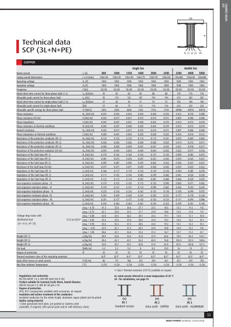
130<strong>SCP</strong>SUPER COMPACTTechnical dataH<strong>SCP</strong> (3L+N+PE)N L1 L2 L3 PECOPPERsingle bardouble barRated current I n [A] 800 1000 1250 1600 2000 2500 3200 4000 5000Casing overall dimensions L x H [mm] 130x130 130x130 130x130 130x170 130x170 130x220 130x380 130x440 130x480Operating voltage U e [V] 1000 1000 1000 1000 1000 1000 1000 1000 1000Insulation voltage U i [V] 1000 1000 1000 1000 1000 1000 1000 1000 1000Frequency f [Hz] 50/60 50/60 50/60 50/60 50/60 50/60 50/60 50/60 50/60Rated short-time current for three-phase fault (1 s) I CW [kA]rms 45 50 60 85 88 88 170 176 176Allowable peak current for three-phase fault I pk [kA] 95 110 132 187 194 194 374 387 387Rated short-time current for single-phase fault (1 s) I CW [kA]rms 27 30 36 51 53 53 102 106 106Allowable peak current for single-phase fault [kA] 57 66 79 112 116 116 224 232 232Allowable specific energy for three-phase fault I 2 t [MA 2 s] 2025 2500 3600 7225 7744 7744 28900 30976 30976Phase resistance R 20 [mΩ/m] 0.041 0.032 0.032 0.024 0.020 0.016 0.012 0.010 0.008Phase reactance (50 Hz) X [mΩ/m] 0.023 0.017 0.017 0.015 0.014 0.011 0.007 0.006 0.006Phase impedance Z [mΩ/m] 0.047 0.037 0.037 0.028 0.024 0.019 0.014 0.012 0.010Phase resistance at thermal conditions R t [mΩ/m] 0.045 0.037 0.040 0.029 0.024 0.019 0.015 0.013 0.010Neutral resistance R 20 [mΩ/m] 0.023 0.017 0.017 0.015 0.014 0.011 0.007 0.006 0.006Phase impedance at thermal conditions Z [mΩ/m] 0.050 0.041 0.043 0.033 0.028 0.022 0.016 0.014 0.012Resistance of the protective conductor (PE 1) R PE [mΩ/m] 0.125 0.125 0.125 0.113 0.113 0.101 0.075 0.069 0.065Resistance of the protective conductor (PE 2) R PE [mΩ/m] 0.036 0.036 0.036 0.028 0.028 0.023 0.014 0.012 0.011Resistance of the protective conductor (PE 3) R PE [mΩ/m] 0.050 0.050 0.050 0.041 0.041 0.033 0.021 0.018 0.017Reactance of the protective conductor (50 Hz) X PE [mΩ/m] 0.054 0.054 0.054 0.044 0.044 0.032 0.022 0.017 0.016Resistance of the fault loop (PE 1) R o [mΩ/m] 0.170 0.162 0.165 0.142 0.137 0.120 0.090 0.082 0.075Resistance of the fault loop (PE 2) R o [mΩ/m] 0.081 0.073 0.076 0.057 0.052 0.042 0.029 0.025 0.021Resistance of the fault loop (PE 3) R o [mΩ/m] 0.095 0.087 0.090 0.070 0.065 0.052 0.036 0.031 0.027Reactance of the fault loop (50 Hz) X o [mΩ/m] 0.077 0.071 0.071 0.059 0.058 0.043 0.029 0.023 0.022Impedance of the fault loop (PE 1) Z o [mΩ/m] 0.186 0.177 0.179 0.154 0.149 0.128 0.094 0.085 0.078Impedance of the fault loop (PE 2) Z o [mΩ/m] 0.111 0.102 0.104 0.082 0.078 0.060 0.041 0.034 0.030Impedance of the fault loop (PE 3) Z o [mΩ/m] 0.122 0.112 0.114 0.092 0.087 0.068 0.046 0.039 0.035Zero-sequence resistance phase - N R o [mΩ/m] 0.170 0.155 0.155 0.115 0.120 0.098 0.083 0.071 0.062Zero-sequence reactance phase - N X o [mΩ/m] 0.159 0.151 0.151 0.114 0.098 0.065 0.056 0.055 0.042Zero-sequence Impedance phase - N Z o [mΩ/m] 0.233 0.216 0.216 0.162 0.155 0.118 0.100 0.090 0.075Zero-sequence resistance phase- PE R o [mΩ/m] 0.507 0.429 0.429 0.331 0.283 0.221 0.177 0.178 0.144Zero-sequence reactance phase - PE X o [mΩ/m] 0.201 0.177 0.177 0.143 0.150 0.124 0.111 0.094 0.086Zero-sequence Impedance phase - PE Z o [mΩ/m] 0.545 0.464 0.464 0.361 0.320 0.253 0.209 0.201 0.168cos = 0.70 41.3 33.0 34.6 27.1 23.5 18.5 13.2 11.5 9.8cos = 0.75 42.1 33.8 35.5 27.7 23.9 18.8 13.5 11.8 9.9Voltage drop factor withcos = 0.80 42.8 34.5 36.3 28.1 24.2 19.1 13.8 12.1 10.0distributed loadk [V/m/A]10 -6 cos = 0.85 43.3 35.0 37.0 28.4 24.4 19.2 14.0 12.2 10.1V = k . L . I .e10-6[V]cos = 0.90 43.4 35.3 37.3 28.5 24.4 19.2 14.1 12.3 10.1cos = 0.95 42.9 35.1 37.2 28.2 23.9 18.8 14.0 12.2 9.8cos = 1.00 38.6 32.1 34.4 25.4 21.2 16.7 12.7 11.2 8.7Weight (PE 1) p [kg/m] 28.9 32.6 32.6 41.8 47.9 60.6 79.0 93.4 116.7Weight (PE 2) p [kg/m] 38.4 42.1 42.1 54.2 60.3 76.8 103.4 122.3 148.6Weight (PE 3) p [kg/m] 32.0 35.7 35.7 45.8 51.9 65.9 87.0 102.8 127.1Fire load [kWh/m] 4.5 5.5 5.5 8 8.2 10.5 16 19 21Degree of protection IP 55 55 55 55 55 55 55 55 55Thermal resistance class of the insulating materials B/F * B/F * B/F * B/F * B/F * B/F * B/F * B/F * B/F *Joule effect losses at rated current P [W/m] 86 111 186 225 294 361 451 619 750Min/Max Ambient Temperature [°C] -5/50 -5/50 -5/50 -5/50 -5/50 -5/50 -5/50 -5/50 -5/50* Class F thermal resistance (155°C) available on request- Regulations and conformity:IEC/EN 60439-1 2; DIN VDE 0660 500 502- Product suitable for Constant/Cyclic Warm, humid climates:DIN IEC 68 part 2-3; DIN IEC 68 part 2-30- Degree of protection:IP55; IPx7 carrying lines available with accessories, on request- Insulation and surface treatment of the conductors:Insulated conductors for the whole length, aluminum copper-plated and tin-plated- Busbar casing material:1.5mm galvanized steel plate, pre-painted or stainless steel(available, if required, with special paint and/or with thickness 2mm)In: rated current referred to a room temperature of 40 °CΔV : for calculations, see page 94(*)PE 1Standard version(*)PE 2Extra earth - COPPER(*)PE 3Extra earth - ALUMINIUM53HIGH POWER GENERAL CATALOGUE