G631 Series - Moog Inc
G631 Series - Moog Inc
G631 Series - Moog Inc

You also want an ePaper? Increase the reach of your titles
YUMPU automatically turns print PDFs into web optimized ePapers that Google loves.
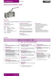
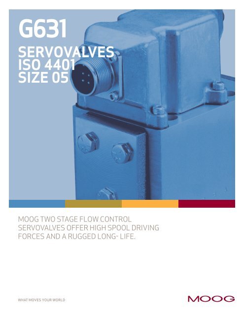
<strong>G631</strong> SERIESGENERAL TECHNICAL DATAOperating PressureMain stage: ports P, X, A and Bport TTemperature RangeFluidAmbientSeal Material*Operating Fluid4,500 psi [315 bar]2,000 psi [140 bar]-20˚ to 275˚F [-29˚ to 135˚C]-20˚ to 275˚F [-29˚ to 135˚C]Fluorocarbon (Viton)Compatible with commonhydraulic fluids, other fluidson request.Recommended viscosity 60 – 450 SUS @ 100˚FSystem Filtration: High pressure filter (without bypass,but with dirt alarm) mounted in the main flow and, ifpossible, directly upstream of the valve. Refer to <strong>Moog</strong>filtration catalog for recommended filtration scheme.Class of Cleanliness: The cleanliness of the hydraulic fluidgreatly effects the performance (spool positioning, highresolution) and wear (metering edges, pressure gain, leakage)of the servovalve.Recommended Cleanliness ClassFor normal operation ISO 4406 < 16/13For longer life ISO 4406 < 15/12Recommended Filter RatingFor normal operationFor longer lifeInstallation OperationsVibrationWeightDegree of ProtectionShipping Plate* Other seal materials available upon requestß 15 ≥ 75 (15 µm absolute)ß 10 ≥ 75 (10 µm absolute)Any position,fixed or movable.15 g, 3 axes4.7 lbs [2.1 kg]EN60529P: class IP65, withmating connector mounted.Delivered with an oil sealedshipping plate.Flow Rate (gpm)50403020105.04.03.02.01.00.60.520.0 gpm[75 lpm]15.0 gpm[60 lpm]10.0 gpm[40 lpm]5.0 gpm[20 lpm]2.5 gpm[10 lpm]1.0 gpm[5 lpm]<strong>G631</strong>-3006B<strong>G631</strong>-3005B<strong>G631</strong>-3004B<strong>G631</strong>-3003B<strong>G631</strong>-3002B<strong>G631</strong>-3001B200 300 400 1000 2000 4500Valve Pressure Drop ∆p (psi)Valve Flow DiagramValve flow for maximum valve opening (100% commandsignal) as a function of the valve pressure drop.X T A P B3
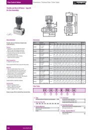
<strong>G631</strong> SERIESTECHNICAL DATAModel…Type<strong>G631</strong>-………Mounting PatternISO 4401-05-05-0-94 (for 4 ports)Valve Body Version4-way2-stage with spool–bushing assemblyPilot StageNozzle/FlapperPilot ConnectionOptional, Internal or ExternalFluid Supply<strong>G631</strong> series servovalves are intended to operatewith constant supply pressureSupply Pressure minimum 200 psi [14 bar]maximum standard4,500 psi [315 bar]Rated Flow Tolerance @ 1,000 psi ∆PN [%] ±10Symmetry [%] < 10Threshold [%] < 1.0Hysteresis [%] < 3.0Null Shift at ∆T = 100˚F [55°K] [%] < 4.0for every 1,000 psi [70 bar] supply pressure change < 4.0Spool Stroke in [cm] .05 [.127]Spool Drive Area in 2 [cm 2 ] 0.12 [.75]Typical Response Characteristic Curves measured at 3,000 pilot pressure, fluid viscosity of 100 SUS and fluid temperatureof 100˚F.Frequency ResponseStep ResponseAmplitude Ratio (dB)+20-2-4-6-8-103,000 PSI DTE -24AT 100˚F (38˚C)±25%INPUT AMPLITUDE1 2 3 5 7 10 20 30 50 70100Frequency (Hz)Frequency Response9070503010Phase Lag (degrees)Stroke (% max)1007550250 10 20 30 40 50Time (ms)Step Response4
<strong>G631</strong> SERIESINSTALLATION DRAWINGS1.812.90646.0023.001.06327.002.12654.004X .256[6.50] THRU.437[11.1]TO DEPTH SHOWN.0112.29PIN DPIN AELECTRICALCONNECTOR2.95[74.9]5.43 MAX[137.9]NULL ADJUSTCOVER SCREWPIN CPIN B1.39[35.3]1.58[40.1]2.60[66.0]4.67 MAX[118.6]3.84[97.5]2.29[58.2]4.20[106.7]1.38[35.0]2.76[70.0]3.15 MAX[80.0]REPLACABLEFILTERP PORTBore 23.72[94.5]X PORTBore 1Standard electricalconnector mates withMS3106F14S-2Sor equivalent.YXTF1F4AXPBF2F3U.S. P A B T X F1 F2 F3 F4Ø.44 Ø.44 Ø.44 Ø.44 Ø.125 1 / 4 20 1 / 4 20 1 / 4 20 1 / 4 20X 1.06 0.66 1.47 0.13 -0.35 0 2.13 2.13 0Y 0.25 0.84 0.84 1.28 0.25 0 0 1.81 1.81METRIC P A B T X F1 F2 F3 F4Ø11.2 Ø11.2 Ø11.2 Ø11.2 Ø3.2 M6 M6 M6 M6X 27 16.7 37.3 3.2 -9 0 54 54 0Y 6.3 21.4 21.4 32.5 6.3 0 0 46 46The mounting manifoldmust conform toISO 4401-05-05-0-94** Note: Location of X port invalve body does not correspondto ISO standards.Mounting surface needs to beflat within 0.001[0.03] TIR anda 32 [∆∆] finish.For external null adjust:Flow out of port “A” will increasewith clockwise rotation of nulladjust screw (1/8 hex key).optionalX externalCONVERSION INSTRUCTIONFor operation with internal orexternal pilot connection.Pilot flow Screw & Seal Washer Location (M4 X 6 DIN EN ISO 4762)supply Bore 1 Bore 2Internal P closed openExternal X open closed5
<strong>G631</strong> SERIESELECTRICAL CONNECTIONSRated current andcoil resistanceA variety of coils areavailable for <strong>G631</strong><strong>Series</strong> Servovalves.Coil connectionsA four-pin electricalconnector (that mateswith an MS3106F14S-2S)is standard. All four torquemotor leads are availableat the connector so externalconnections can be madefor series, parallel, orsingle operation.ServoamplifierThe servovalve respondsto input current, so aservoamplifier that hashigh internal impedance(as obtained with currentfeedback) should be used.This will reduce the effectsof coil inductance and willminimize changes due tocoil resistance variations.ELECTRICALCONNECTIONS(Examples with typical <strong>G631</strong> series coils)Parallel<strong>Series</strong>SingleA B C D A B C D A B C DCoil ResistanceRated CurrentCoil Inductance @ 50 HzElectrical PowerPolarity for Valve OpeningP ➧ B, A ➧ T[Ω][mA][H][W]14±1000.2.14A and C (+)B and D (-)56±500.8.14A (+), D (-)B and C connected28±1000.2.28A (+), B (-)or C (+), D (-)Note: Before applying electrical signals, the pilot stage must be pressurized.6
<strong>G631</strong> SERIESORDERING INFORMATIONSPARE PARTS AND ACCESSORIESSTANDARD MODELSModelType DesignationRated Flow(∆ 1,000 psi)gpm lpm<strong>G631</strong>-3001A H05JOFM4VBR 1.0 5.0 < 0.52 < 2.0 100 28<strong>G631</strong>-3002A H10JOFM4VBR 2.5 10 < 0.60 < 2.3 100 28<strong>G631</strong>-3003A H20JOFM4VBR 5.0 20 < 0.70 < 2.6 100 28<strong>G631</strong>-3004A H40JOFM4VBR 10.0 40 < 0.78 < 3.0 100 28<strong>G631</strong>-3005A H60JOFM4VBR 15.0 60 < 0.86 < 3.2 100 28<strong>G631</strong>-3006A H75JOFM4VBR 20.0 75 < 0.96 < 3.6 100 28*Overdrive more than 10% of rated current is NOT recommended.Internal Leakage(at 3,000 psi)gpm lpmRated Current(Single Coil)*mANominal CoilResistanceOhmsOptional Feature<strong>Series</strong> specificationModel Number<strong>G631</strong>• • • • • AType DesignationH • • • • F M • V B • –Special Equipment– NoneModel DesignationAssigned at the factoryFactory Identification (Revision Level)Valve VersionHRated Flow QN gpm [lpm]At ∆PN = 75 psi [5 bar] per land At ∆PN = 500 psi [35 bar] per land05 0.4 [1.5] 1 [5]10 1 [3.7] 2.5 [10]20 2 [7.5] 5 [20]40 4 [15] 10 [40]60 6 [22] 15 [60]75 8 [30] 20 [75]Maximum Operating Pressure (P) and Body MaterialJ 4,500 psi [315 bar] AluminumSignals for 100% Spool StrokeQ ±15 mA (series)R ±50 mA (series)Valve ConnectorB Connector over B-sideSeal MaterialV FPM (Viton)Pilot Connections and Pressure4 Internal5 ExternalSpool Position without Electrical SignalM Mid-positionPilot StageF Standard Flow, Nozzle-FlapperBushing/Spool TypeO 4-way / axis cut / linearD 4-way / ±10% overlap / linearSPARE PARTS AND ACCESSORIES<strong>Moog</strong> Part Size <strong>Moog</strong> Part NumberO-Rings (included in delivery),FPM 85 Shorefor P,T,A and B ID 0.472 x 0.079 G2141-012-020for X ID 0.315 x 0.079 G2141-008-020Mating Connector (not included in delivery)P/N 49054F014S002S(MS3106F14S-2S)Flushing Block P/N B67728-002Mounting Bolts (not included in delivery)1/4 - 20 NC x 2-3/4 long (4 pieces) P/N A31324-144B[M6 x 1.0 x 70 mm] [B64929-7B70]Replaceable Filter P/N A67999-100Filter Replacement Kit (includes service manual)P/N B52555RK200K0017
TAKE A CLOSER LOOKSolutions for flow control of high performance applications are available around the world. For more information,visit our Web site or contact one of the locations below.Argentina+54 11 4326 5916info.argentina@moog.comAustralia+61 3 9561 6044info.australia@moog.comAustria+43 664 144 65 80info.austria@moog.comBrazil+55 11 5523 8011info.brazil@moog.comChina+86 21 5854 1411info.china@moog.comFinland+358 9 2517 2730info.finland@moog.comFrance+33 1 4560 7000info.france@moog.comGermany+49 7031 6220info.germany@moog.comHong Kong+852 2 635 3200info.hongkong@moog.comIndia+91 80 4120 8799info.india@moog.comIreland+353 21 451 9000info.ireland@moog.comItaly+39 0332 421 111info.italy@moog.comJapan+81 436 55 3767info.japan@moog.comKorea+82 31 764 6711info.korea@moog.comLuxembourg+352 40 46 401info.luxembourg@moog.comNetherlands+31 252 462 000info.netherlands@moog.comNorway+47 224 32927info.norway@moog.comRussia+7 317131811info.russia@moog.comSingapore+65 677 36238info.singapore@moog.comSouth Africa+27 11 655 7030info.southafrica@moog.comSpain+34 902 133 240info.spain@moog.comSweden+46 31 680 060info.sweden@moog.comSwitzerland+41 71 394 5010info.switzerland@moog.comUnited Kingdom+44 1564 784 777info.uk@moog.comUSA+1 716 652 2000info.usa@moog.comwww.moog.com/industrial©2007 <strong>Moog</strong>, <strong>Inc</strong>.All trademarks as indicated herein are the property of <strong>Moog</strong>, <strong>Inc</strong>.and its subsidiaries. All rights reserved.<strong>G631</strong> CDL6641 RevK 500-339 1008TJW/PDFWHAT MOVES YOUR WORLD