Hydraulic Accessories Local solutions for individual customers ...
Hydraulic Accessories Local solutions for individual customers ...
Hydraulic Accessories Local solutions for individual customers ...
- No tags were found...

Create successful ePaper yourself
Turn your PDF publications into a flip-book with our unique Google optimized e-Paper software.
STAUFF<strong>Hydraulic</strong> <strong>Accessories</strong><strong>Local</strong> <strong>solutions</strong> <strong>for</strong><strong>individual</strong> <strong>customers</strong>worldwide
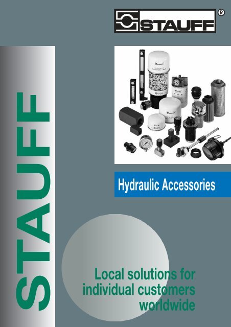
Walter Stauffenberg GmbH & Co. KGP.O.Box 1745 • 58777 Werdohl • GermanyIm Ehrenfeld 4 • 58791 Werdohl • GermanyTelephone: + 49 2392 916-0Facsimile: + 49 2392 2505E-Mail: sales@stauff.comInternet: www.stauff.com• Comprehensive choice• Immediate delivery• High quality standardThe STAUFF hydraulic accessories programme hasbeen carefully designed to offer a range of componentssuited to the demands of building hydraulicsystems in most industrial and mobile applications.Whether you require simple filler breathers or preciseelectrical level switches, flow control valves orcomplete filter units; the STAUFF accessories rangeshould provide you with the choice you need.At STAUFF we are aware of the ongoing developmentand innovation within the hydraulic industry.We strive to keep up with and further develop thelatest technology and to bring the benefit of any suchimprovements directly to the customer.Additionally we are always prepared to considercustom built products, if you have a special need.We ensure that your most urgent requirements are metby keeping a large and comprehensive stockholdingboth in Germany and in our overseas locations.These products are subject at all times to ourEN ISO 9001:2000 Quality Management Systems.AUSTRALIASTAUFF Corporation Pty. Ltd.P.O. Box 227Unanderra, NSW, 252624-26 Doyle AvenueUnanderra Wollongong, NSW, 2526Telephone: +61 2 4271 18 77Facsimile: +61 2 4271 84 32sales@stauff.com.auBRAZILSTAUFF Brasil Ltda.Avenida Gupê 10767Galpão 2 - Bloco ABarueri - São PauloCEP 06422-120Telephone: +55 11 47 72 72 00Facsimile: +55 11 47 72 72 10stauff@stauffbrasil.comCANADASTAUFF Canada Ltd.866 Milner AvenueScarboroughOntario M1B 5N7Telephone: +1 416 282 46 08Facsimile: +1 416 282 30 39sales@stauffcanada.comCHINASTAUFF International Trading(Shanghai) Co., Ltd.Shangdian Mansion, Pudong551, Gaoke Road (W.)200126 ShanghaiTelefon: +86 21 58 45 65 60Telefax: +86 21 58 45 66 80stauffsh@public.sta.net.cnFRANCESTAUFF S.A.230, Avenue du Grain d'OrZ.I. de Vineuil - Blois Sud41354 Vineuil-cedexTelephone: +33 2 54 50 55 50Facsimile: +33 2 54 42 29 19direction@stauffsa.comINDIASTAUFF India Pvt. Ltd.Gat. No. 2340Pune Nagar Road, WagholiPune, 412207Telephone: +91 20 3293 0124Facsimile: +91 20 2705 1567sales@stauffindia.comIRELANDSTAUFF IrelandUnit B3Weatherwell Business ParkClondalkinDublin 22Telephone: +353 (0)1457 4936Facsimile: +353 (0)1467 0687sales@stauff.ieITALYSTAUFF Italia s.r.l.Viale Nuova Valassina 78angolo Via Baragiola sn20033 Desio (Mi)ItaliaTelephone: +39 0362 63 80 70Facsimile: +39 0362 63 80 69sales@stauff.itKOREASTAUFF Korea Ltd.1500-12, Dadae-DongSaha-KuPusan, 604-826Telephone: +82 51 266 6666Facsimile: +82 51 266 8866info@stauff.co.krNEW ZEALANDSTAUFF Corporation (NZ) Ltd.P. O. Box 58517Greenmount, AucklandUnit D, 103 Harris RoadEast Tamaki, AucklandTelephone: +64 9 271 48 12Facsimile: +64 9 271 48 32info@stauff.co.nzPOLANDSTAUFF Polska Sp. z o.o.ul. Rdestowa 5181-591 GdyniaTelephone: +48 (58) 660 11 60Facsimile: +48 (58) 629 79 52sales@stauff.plRUSSIAN FEDERATIONSTAUFF LLCOffice 205, Building 711, ScharikopodschipnikovskayaMoscow, 115088Telephone: +7 495 223 89 61 and+7 495 679 90 08Facsimile: +7 495 679 90 48sales@stauff.ruUNITED KINGDOMSTAUFF UK Ltd.500, Carlisle Street EastOff Downgate DriveSheffield, S4 8BSTelephone: +44 114 251 85 18Facsimile: +44 114 251 85 19sales@stauff.co.ukUNITED STATES OF AMERICASTAUFF Corporation7 Wm. Demarest PlaceWaldwick, 07463-1542New JerseyTelephone: +1 201 444 78 00Facsimile: +1 201 444 78 52sales@stauffusa.comDistributors and warehousesin all industrial countries.2
ContentsSTAUFF <strong>Hydraulic</strong> <strong>Accessories</strong>PageLevel Gauges SNA 4Level Gauges SNK 5Thermo Switches TS (<strong>for</strong> SNA and SNK) 6Level-Temperature Switches SLTS 7Throttle and Flow Control Valves DV/DRV (In-line mounting) 8Throttle and Flow Control Valves DVP/DRVP (Manifold mounting) 9Throttle Valves DVE (Cartridge assembly) 10Flow Curves DV/DRV-DVP/DRVP-DVE 11Check Valves RV (In-line mounting) 12Plastic Filler Breathers SPB 13-15Plastic Filler Breathers SPBN (Narrow Version) 16-17Metal Filler Breathers 18-21SMBB (Bayonet style)/SMBT (Screw-in style)/SMBP (Push-on style)Angled side Mounting Brackets SMBB-ASMB 22Lockable Metal Filler Breathers SMBL 23Plastic Filler Breather SES 24Giant Air Breathers SGB 25Desiccant Air Breathers SDB 26-27Inclusive accessories: adaptor plates (AP), contamination indicator (FM),Drying agent refilling material (RD); replacement air filter inserts (SGB)Suction Strainers SUS 28Diffusers SRV 29Flow Indicators SDM / SDMK 30-31Pressure Gauges SPG 32-33Gauge Isolator Valves (Single/Multi Station) SWS 34Return Line Bushings SRF 35In the past you found in<strong>for</strong>mation about our Spin-on-filters product range here.This in<strong>for</strong>mation now has been summarized in our new catalogue “Spin-on-filters”, please contact STAUFF oryour local distributor <strong>for</strong> your personal copy.3
Thermo Switches TS (<strong>for</strong> SNA and SNK)DimensionsArea of Application: Oil temperature indication inconjunction with STAUFF level gauges SNA and SNKCharacteristics/Materials:• available with 60°C, 70°C or 80°C switching temperature• Activation takes place when the respective switching temperatureis exceeded.• Electrical function: break contact• With plug according to DIN EN 175301-803-B/ISO6952 (industrystandard) or with plug according to IEC 61076 - 2-101 M12 (type OD)• Steel parts made out of steel (1.0718)• Plastic parts made out of glass fibre rein<strong>for</strong>ced PolyamideThermo switches are available <strong>for</strong> the standard mounting size M12 only.Technical Data115▫17SW 13Switching temperature: see ordering codeHysteresis:20° CSwitching temperature tolerance: 5°C.Alternating current• max voltage 250 V321thermostatcable 2ground cablethermostatcable 1• max current at 10.000 operations≈ 2.5 A at cos = 1.0≈ 1.6 A at cos = 0.6• max current at 100.000 operations≈ 0.5 A at cos = 1.0≈ 0.25 A at cos = 0.6• min voltage 50 mADirect current• max voltage 42 V• max current at10.000 circuits 1 AExample of applicationOption plugstandard plug type Oaccording toDIN EN 175301-803-B/ISO6952(industry standard)PG9Ø 1033M 122850▫1748M 12 plug, A codedaccording to IEC 61076type ODM123825AOrdering Code and Switching temperaturesSNA : 39SNK : 47SNA : 76SNK : 682855see page 5 <strong>for</strong> electricalconnections and functionsTS - SNA / SNK - O - 60TypeTSSeriesSNA / SNKThermo SwitchThermo switches can be ordered both as a single componentand in combination with STAUFF level gauges SNA and SNK.See pages 4 and 5.Electrical functionOODSwitching temperature60 60°C / 140°F70 70°C / 158°F80 80°C / 176°FBreak Contact (n/c), standard plugBreak Contact (n/c), M12 plug6
Level-Temperature Switches SLTSTechnical DataStem:BrassFloat/Seal:NBRmax operating temperature: 80°Cmax operating voltage:seeordering codemax current (level contact): 0.5 Amax current (temperature contact): 2.0 Acontact load level contact: 10 VAsystem of protection:IP65Hysteresis: 12°CLevel contact positions (L, H) are set asgiven in the chart. They can be adjusted<strong>individual</strong>ly later on.Please consider a minimum distance of40 mm between the switching points.Wiring Scheme <strong>for</strong> type 2LHArea of Application:Electrical level and temperature indicationCharacteristics:• suitable <strong>for</strong> mineral oil and HFC fluids, other fluids on request• either 1 or 2 level contacts available• 1 integrated temperature sensor• standard electrical function:Level contacts: normally closed, opens with falling levelTemperature contact: normally closed, opens with rising temperatureSTAUFF Level-Temperature switches SLTS are availablewith other electrical functions on request.DimensionsHigh-level contactHM3groundSW36164534G 3 /423,5 2541L2L14 2Hø23,513LWiring Scheme <strong>for</strong> type 1L or 1HH or L4 21 3Ordering CodeDimensional TableLow-level contactLSLTS 12 SLTS 18L1 305 457L2 251 403ø11SLTS 12 - 140 - 2LH - B12 - G048TypeSLTSLevel-temperature switchStem Length12 305 mm18 457 mmSwitching temperature140 60°C / 140°F158 70°C / 158°FO without temperature switchVoltage (Volt AC/DC)G048G11548 Volt max (standard)115 Volt max(<strong>for</strong> thread N16 only)ThreadB12 G 3 /4 (standard)N16 1 NPT (only on request)Number of level switches1 1 level switch (L, H)*2 2 level switch (LH)* please indicate level position(s): L = low, H = high7
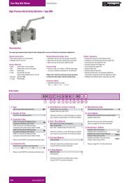
Throttle and Shut-off ValvesFlow Control ValvesDVDRV In-line mountingTechnical Data:max Working Pressure p N : 350 barTemperature tmax: 100°COpening Pressure DRV:0.5 bar (4.5 bar on request)Area of Application: Fluid control and flow shut-off• DV: in both directions• DRV: in direction A-B (free flow in reverse direction)Characteristics/Materials:• designed <strong>for</strong> in-line mounting• suitable <strong>for</strong> mineral oil• Nuts <strong>for</strong> panel-mounting are available on request• Housing: Steel (1.0715), zinc-plated (Fe/Zn 8 C)• Turning knob: PolyamidePlease consult our office be<strong>for</strong>e using with other fluids, or <strong>for</strong>special stainless steel material.DimensionsBDV DV/DRV DRVSymbolAøD1BSymbolAG1øD2SmaxG1H38 9 0 1 2G2H2 (closed)H1 (open)G1øD2G1 SmaxL1L2B1L1L2Dimensional TableNominalDV/DRV DV DRVSize G1 wt. wt.DN BSP NPT G2 H1 H2 H3 B1 D1 D2 Smax L1 L2 (kg) L1 L2 (kg)06 G 1 /8 1/8 NPT PG 7 68,0 63,0 18,0 16 24 13 3 38 19 0.12 45 26,0 0.1308 G 1 /4 1/4 NPT PG 11 83.5 77.5 27,0 25 29 19 7 48 24 0.25 55 33.5 0.3010 G 3 /8 3/8 NPT PG 11 90,0 83,0 32,0 30 29 19 7 58 29 0.40 65 41,0 0.4512 G 1 /2 1/2 NPT PG 16 109.5 99.5 38.5 35 38 23 7 68 34 0.70 73 44,0 0.8016 G 3 /4 3/4 NPT PG 16 128.5 118.5 48.5 45 38 23 7 78 39 1.20 88 57,0 1.3020 G 1 1 NPT PG 29 174,0 157,0 55,0 50 55 38 11 108 54 2.10 127 77,0 2.4025 G 1 1 /4 1 1 /4 NPT PG 29 184,0 167,0 65,0 60 55 38 11 108 54 2.80 143 93,0 3.5030 G 1 1 /2 1 1 /2 NPT PG 29 194,0 177,0 75,0 70 55 38 11 108 54 3.50 143 91,0 4.6040 G 2 2 NPT PG 29 214,0 197,0 95,0 90 55 38 11 – – – 165 111,0 7.70Ordering CodeDV - 25 - P - B - SSType (in-line mounting)DV Throttle and shut-off valveDRV Flow control valveNominal size DN06 08 10 12 16 20 25 30 40 (only DRV)Seal materialP NBR (standard)V FPME EPDMHousing / spindle material(none) Steel (standard)SS Stainless steel (1.4571)Thread <strong>for</strong>mB BSP (standard)N NPT (only on request)8
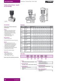
Throttle and Shut-off ValvesFlow Control ValvesDVPDRVP Manifold mountingArea of Application: Fluid control and flow shut-off• DVP: in both directions• DRVP: in direction A-B (free flow in reverse direction)Characteristics/Materials:• designed <strong>for</strong> manifold mounting• suitable <strong>for</strong> mineral oils• Housing: Steel (1.0715), zinc-plated (Fe/Zn 8 C)• Turning knob: PolyamidePlease consult our office be<strong>for</strong>e using with other fluids, or <strong>for</strong>special stainless steel material.Technical Data:max Working Pressure p N : 350 barTemperature tmax: 100°COpening Pressure DRVP:0.5 bar (4.5 bar on request)DimensionsDVPL6L7BSymbolADRVPL6L7BSymbolAB2B1øD1H3T1H2 (closed)H1 (open)D4D3D4D3D6D5D6D5B2B1L5L4L3L1L5L9L4L3L1L8øD1T1H3H2 (closed)H1 (open)G2, D2 und Smaxsee Dimensional Table DV/DRV (page 8)inclusive of O-ringsinclusive of O-ringsDimensional TableNom.DVP and DRVP DVP DRVPSize wt. wt.DN D1 D3 D4 D5 D6 L3 L4 L7 B1 B2 T1 O-Ring L1 L5 L6 H1 H2 H3 (kg) L1 L5 L6 L8 L9 H1 H2 H3 (kg)06 24 6.6 11 5 9.8 19 – 16 41.5 28.5 7 6.75 x 1.78 35 8 9.5 68 63 16 0.2 41.5 6.4 8 43 13.5 68 63 16 0.2608 29 6.6 11 7 12.4 35 – 25.5 46 33.5 7 8.5 x 2 47.5 6.5 11 79 72 20 0.4 63.5 14.2 16.7 65 31 79 72 20 0.510 29 6.6 11 10 15.7 33.5 – 25.5 51 38 7 12 x 2 51 8.5 12.7 84 78 25 0.6 70 18 22 73 29.5 84 78 25 0.812 38 6.6 11 13 18.7 38 – 30 57.5 44.5 7 15 x 2 75 18.5 22.5 100 89 25 1.0 80 21 25 84 36.5 107 96 32 1.216 38 8.5 13.5 17 23.9 76 38 54 70 54 9 19 x 2.5 93.5 8.5 19.5 113 103 30 1.5 104 14 25.4 108 49 128 118 45 2.520 55 8.5 13.5 22 30.5 95 47.5 57 76.5 60 9 25 x 3 111 8 27 169 152 45 3.4 127 16 35 131 49 174 157 50 3.925 55 11 18 28.5 37.5 120 60 79.5 100 76 11 32 x 3 143 11 32 169 152 45 5.15 165 15 35.6 169 77 179 162 55 6.730 55 14 20 35 43.5 143 71.5 95 115 92 13 38 x 3 171 15 39 174 157 50 7.5 186 15 38.8 190 85 199 182 75 11.040 55 14 20 47.5 57.5 133.5 67 89 140 111 13 52 x 3 – – – – – – – 192 15 40.5 196 64 224 207 100 18.8Ordering CodeDVP - 25 - P - SSType (manifold mounting)DVP Throttle and shut-off valveDRVP Flow control valveNominal size DN06 08 10 12 16 20 25 30 40 (only DRVP)Housing/spindle material(none) Steel (standard)SS Stainless steel (1.4571)Seal materialP NBR (standard)V FPME EPDM9
Flow Curves DV/DRV – DVP/DRVP – DVEDV/DRV-06DVP/DRVP-0610080600.5Throttle per revolution0.25 1 1.5 2 2.5 3 3.5 4DV/DRV-08DVP/DRVP-08DVE-08Throttle per revolution0.50.25 1 1.5 2 2.5 3 3.5 4 4.510080605p in bar404.5p in bar40202051010550 2 4 6 8 10 12 14 Q in l/min0 10 20 30 40 50 60 Q in l/minDV/DRV-10DVP/DRVP-10DVE-10100806040Throttle per revolution0.25 0.5 1 1.5 2 2.5 3 3.5 4 4.5 5 5.5 66.577.58DV/DRV-12DVP/DRVP-12DVE-12Throttle per revolution0.50.25 1 1.5 2 2.5 3 3.5 4 4.5 5 5.5 6 6.5 7 7.5 8 8.5 91008060409.510p in bar20p in bar201010550 10 20 30 40 50 60 70 75 Q in l/min0 20 40 60 80 100 120 140 Q in l/minDV/DRV-16DVP/DRVP-16DVE-16p in bar10080604020Throttle per revolution0.25 1 20.5 1.5 2.5 3 3.5 4 4.5 5 5.5 6 6.5 7 7.5 88.599.510DV/DRV-20/25/30/40DVP/DRVP-20/25/30/40p in bar10080604020Throttle per revolution0.250.5 1 1.5 2 2.5 3 3.5 4 4.5 5 5.5 66.577.588.599.5101010550 25 50 75 100 125 150 175 Q in l/min0 50 100 150 200 250 300 350 Q in l/minDRV-06-40DRVP-06-40p in bar141210864Flow direction: B–Ap Characteristic curve free flow through check valve-06 -08 -10 -12 -16 -20-25-30-40STAUFF throttle and flow control valves aredesigned to shut off and control the flow ofliquid media. The flow rate is regulated on adirect reading device by turning the handlefrom completely closed to fully open and isset by screws.The increase in flow is also indicated by acolour and number scale. This is revealed ona central spindle emerging from the turningduring operation.20.5100 200 300 400 500 600 Q in l/minThe values given refer to a viscosity of 35 cSt.11
Check Valves RV (In-line mounting)Area of Application:Check valves allow a single-directional flow only.Characteristics/Materials:• designed <strong>for</strong> in-line mounting• suitable <strong>for</strong> mineral oil• Housing: Steel (1.0715), zinc-plated (Fe/Zn 8 C)• Standard thread <strong>for</strong>m: BSP; NPT on request• metal-to-metal sealsPlease consult our office be<strong>for</strong>e using with other fluids, or <strong>for</strong>special material and thread sizes.Technical Data:Temperature tmax: 100°COpening Pressure RV: 0.5 bar (4.5 bar on request)DimensionsRV-06-40141210Flow direction: B–Ap Characteristic curve free flow through check valve-06 -08 -10 -12 -16 -20-25BSymbolAp in bar864-30-40BG1G1A20.5100 200 300 400 500 600 Q in l/minThe values given refer to a viscosity of 35 cSt.L1 B1Dimensional TableNominal SizeG1p N (bar)DN BSP NPTL1 B1 Weight (kg)06 500 G 1 /81/8 NPT 45 16 0.108 500 G 1 /41/4 NPT 55 25 0.210 500 G 3 /83/8 NPT 65 30 0.412 500 G 1 /21/2 NPT 73 35 0.716 500 G 3 /43/4 NPT 88 45 1.220 500 G1 1 NPT 127 50 2.025 400 G1 1 /4 1 1 /4 NPT 143 60 3.330 315 G1 1 /2 1 1 /2 NPT 143 70 4.240 315 G2 2 NPT 165 90 7.2Ordering CodeRV - 25 - 07 - B - SSTypeRVCheck valveNominal size DN06 08 10 12 16 20 25 30 40Opening pressure07 0.5 bar (7 PSI) (standard)65 4.5 bar (65 PSI)Material(none) Steel (standard)SS Stainless steel (1.4571)Thread sizeB BSP (standard)N NPT (only on request)12
Plastic Filler Breathers SPBDimensions and Styles – Screw-in versions (Breathers)Area of Application:Ventilation and tank fillingCharacteristics/Materials:• available as screw-in or bayonet version• non-corrosive• Temperature range: – 40°C ... +120°C• Materials: glassfibre rein<strong>for</strong>ced PA, basket PP• Seals:NBR, others on request• Air filter insert: see order table page 15Custom built combinations and special requirements availableon request.SPB 1 SPB 2 SPB 3Ø70Ø101Ø45476475SW 27G 1/4G 3/8G 1/213.5SW 30G 3/8G 1/2G 3/419.5SW 36G 1/2G 3/4G 119.5max Rate of Air flow: 0,15 m 3 /min max Rate of Air flow: 0,4 m 3 /min max Rate of Air flow: 1,0 m 3 /minDimensions and Styles – Bayonet version (Filler Breathers)SPB 4clamping jaw installationØ10167.5SPB 5six hole reservoir installationInterface similar to DIN 24557, part 2Ø10167.5Note:Installationof the SPB 5In order to install theSPB 5, 6 holes on a73 mm bolt circlediameter are necessary.Depending on thematerial thickness,we recommend thefollowing dimensions<strong>for</strong> the mounting holes(see chart):recommended valuesmax 1097max 1097sheet holethickness size(mm) (mm)1.20 4.02.00 4.13.15 4.34.00 4.35.00 4.4min Ø63max Rate of Air flow: 1,0 m 3 /mintappingscrewsISO 7049-ST4.8x16-C-H(6x)min Ø63BCD = Ø73max Rate of Air flow: 1,0 m 3 /minBolt delivery standard:Tapping screws (canoptionally be replacedwith normal M5 boltsby the customer).13
Plastic Filler Breathers SPBBreather options:• Dipsticks (material PA)• Pressurised versions (<strong>for</strong> SPB 2 up to SPB 5)• Baskets (<strong>for</strong> SPB 4 and SPB 5)• Thread <strong>for</strong>m NPT (<strong>for</strong> SPB 1 up to SPB 3)Special executions available on request.Dipsticks and Anti-splash featureØD8.5D200 = 200D300 = 300greenred3.4withintegratedanti-splashfunctionadjustablePhoto: integrated anti-splash featureAdaptation <strong>for</strong>m <strong>for</strong> type suitable dipstick Dimension ØDB04 SPB 1 n/a –B06 SPB 1 + 2 DS-1 10B08 SPB 1 – 3 DS-2 14B12 SPB 2 + 3 DS-3 18B16 SPB 3 DS-3 18S080 SPB 4 + 5 DS-3 18S200 SPB 4 + 5 DS-3 18X SPB 4 + 5 DS-3 18For all filler breathers SPB 1 up to SPB 5, dipsticks (material Polyamide)are available as an option. All these dipsticks have an integrated anti-splashfunction. This anti-splash feature protects the SPB from backspilling fluidand avoids an early air filter breakdown. For filler breathers without dipstickthe anti-splash function is achieved by an integrated concave baffle.Because of its small size the anti-splash function <strong>for</strong> the size 1 can only beachieved in conjunction with a dipstick. Depending on the chosen fillerbreather (see table above), dipsticks are available in two standard lengths(200 mm and 300 mm). Smaller dipstick sizes can be achieved by simplycutting down its length on site, according to <strong>individual</strong> requirements.Pressurised versions:Optionally all filler breathers, except size 1, are available as pressurised breathers. In order to achieve an air flow,the tank pressure has to exceed the chosen pressure setting. This feature minimizes foaming and cavitation.Available pressure settings: 0.2 bar, 0.35 bar and 0.7 bar.Baskets <strong>for</strong> SPB 4 and 5basketS080telescopic basketS200For the filler breathers SPB 4 and SPB 5, 80 mm and 200 mm baskets(material Polypropylene) are available as an option. All baskets have arein<strong>for</strong>ced 0.8 x 3.5 mm mesh. With the basket S080 and the telescopicbasket S200, rough dirt particles are filtered out of the medium and asmooth flow into the tank is being ensured.max 205ø41.5ø29.5ø41.514
Plastic Filler Breathers SPBOrdering CodeSPB - S - 2 - 10 - B12 - A - D300TypSPBVersionSP1P2P3Plastic filler breather(Pressurisation not available <strong>for</strong> SPB 1)without pressurisation (standard)pressurised at 0.20 barpressurised at 0.35 barpressurised at 0.70 barGroup sizesize versioncap max rate of airdiameter flow (m 3 /min)1 screw-in version 45 0.152 screw-in version 70 0.453 screw-in version 101 1.054 single hole reservoir installation 101 1.055 six hole reservoir installation 101 1.05Dipstick option(none)D200D300without dipstickdipstick 200 mmdipstick 300 mmAnti-splash optionAOConnectionwith anti-splash option (standard)without anti-splash optionB04 G 1 /4 (<strong>for</strong> SPB 1)B06 G 3 /8 (<strong>for</strong> SPB 1 + 2)B08 G 1 /2 (<strong>for</strong> SPB 1 – 3)B12 G 3 /4 (<strong>for</strong> SPB 2 + 3)B16 G1 (<strong>for</strong> SPB 3)S080 basket (<strong>for</strong> SPB 4 + 5)S200 telescopic basket (<strong>for</strong> SPB 4 + 5)X without basket (<strong>for</strong> SPB 4 + 5)Micron rating and Filter materialcode foam (PUR) code Inorganic glassfiber (only SPB 3,4 and 5) code filter paper (only SPB 3,4 and 5)10 10 µm PUR (standard) E03 3 µm inorganic glass fiber (pleated) L10 10 µm filterpaper (pleated)40 40 µm PUR (on request)other micron ratings or filtermaterial on requestAirflow plastic filler breathers SPB 1 – 5SPB 1into/out of the tankSPB 2into/out of the tankSPB 3into/out of the tankp in bar0.070.060.050.040.030.020.01B04 (in/out)B06 (in/out)B08 (in/out)B12 (in/out)0.00 0,03 0,06 0,09 0,12 0,15 0,18 Q in m 3 /minp in bar0.80.70.60.50.40.30.2P3-B12(out)P2-B12 (out)Px-B12 (in)P1-B12 (out)0.1S-B12 (out)0.0S-B12 (in)0 0,15 0,3 0,45 Q in m 3 /minp in bar0.80.70.60.50.40.3P3-B12 (out)P2-B12 (out)Px-B12 (in)P1-B12 (out)0.20.1S-B12(in/out)0.00 0,2 0,4 0,6 0,8 1,0 Q in m 3 /minp in bar0.80.70.60.50.40.30.20.1SPB 4 und 5into the tank0.00 0,2 0,4 0,6 0,8 1,0 Q in m 3 /minPxSp in bar0.8 P30.70.60.50.40.30.20.1SPB 4 und 5out of the tankP2P10.00 0,2 0,4 0,6 0,8 1,0 Q in m 3 /minS15
Plastic Filler Breathers SPBN (Narrow Version)Area of Application:Ventilation and tank fillingCharacteristics/Materials:• available as screw-in or bayonet version• non-corrosive• Temperature range: -40°C ... +120°C• Materials:glassfibre rein<strong>for</strong>ced PA• Seals:NBR, others on request• Air filter insert: see order table page 17Options:• Plastic dipsticks with integrated anti-splash function• Metal basket (micron rating 800 µm)• Thread style BSP and NPT available• Pressurised at 0,20, 0,35 or 0,70 barCustom built combinations and specialrequirements available on request.Dimensions and Stylesscrew-in versionbayonet versionMounting DetailBCD = 7352Interface similar toDIN 24557, part 26 bores M5max Rate of Air Flow: 0,4 m 3 /minmax Rate of Air Flow: 0,4 m 3 /minSPBN 2 B12 B16 N12 N16G G 3 /4 G 1 3/4 NPT 1 NPTH1 19,5 24 19,5 24H2 69 73,5 69 73,5SW 30 36 30 36<strong>Accessories</strong>: Mounting Adapter <strong>for</strong> Metal Basketslotted pan head screwsISO1580 M5x12-5.8Designation: S-080/100/150/200-M-F-SPBN-BS-NBR16
Plastic Filler Breathers SPBN (Narrow Version)Ordering CodeSPBN - S - 2 - 10 - B12 - A - D300TypeSPBNPlastic Filler Breather- Narrow VersionVersionS without pressurisation (standard)P1 pressurized at 0,20 bar (3 PSI)P2 pressurized at 0,35 bar (5 PSI)P3 pressurized at 0,70 bar (10 PSI)Dipstick option(none)D300without dipstickdipstick 300mmNote: The plastic dipstick can be shortenedby the customer to requested lengths.Anti-splash optionAOwith anti-splash option(only <strong>for</strong> screw-in version)without anti-splash option (standard)Group sizesize cap diameter max rate of air flow (m 3 /min)2 70 0,4Micronrating and Filter MaterialCode foam (PUR)10 10 µm PUR (standard)40 40 µm PUR (standard)ConnectionB12 G 3 /4 BSPB16 G1 BSPN12 3/4 NPT (on request)N16 1 NPT (on request)BS Bayonet version (without accessories)BM Bayonet version (including mountingadaptor, gaskets and bolts)S080 BM + 80 mm metal basketS100 BM + 100 mm metal basketS150 BM + 150 mm metal basketS200 BM + 200 mm metal basketAirflow plastic filler breathers SPBN 2SPBN 2into the tankSPBN 2out of the tankp in bar0.70.60.50.40.30.2SPBN P0.1S0.00 0,15 0,3 0,45 Q in m 3 /minp in bar0.80.7P30.60.50.4P20.3P10.20.1S0.00 0,15 0,3 0,45 Q in m 3 /min17
Metal Filler Breathers SMBB / SMBT / SMBPArea of Application:Ventilation and tank fillingAvailable Versions:Screw-in, bayonet and push-on styleMaterials:• Breather cap: steel, chrome-plated (epoxy on request)• Socket: steel, chrome-plated• Air filter insert: see order table on page 17• Basket: steel, zinc-plated• Seals: Cork, Buna-N (NBR)Options:• Metal basket (micron rating 800 µm)• Thread style BSP and NPT available• Pressurised at 0,35 or 0,70 bar• Lockable• Plastic dipsticksCustom built combinations and specials are available on request.Group size 47 – Breather cap diameter 47 mmSMBB-47Metal Filler BreatherBayonet styleSeal material: corkOptions:• Metall basketSMBT-47Metal BreatherScrew-in styleOptions:• BSP- or NPT-threadBCD = 4129Mounting Detail3 bores M5ø47ø47453 cheese head screwsISO 1580 M5x12-5.84165H1SWGø28BCD=ø41max Rate of Air Flow: 0.4 m 3 /minmax Rate of Air Flow:0.4 m 3 /minTypSMBT-47B04 B06 B08G G 1 /4 G 3 /8 G 1 /2H1 10 13 14SW 17 15 22Metal Filler breathers SMBB-47 and SMBT-47 are not lockable, have no pressurisation option and are not availablewith a dipstick. For more details see order table on page 19.18
Metal Filler Breathers SMBB / SMBT / SMBPOrdering Code (bayonet style, cap ø47)SMBB - 47 - S - 10 - O - C - S065 - OTypSMBBCap sizeVersionSNMetal Filler Breather(bayonet style)47 ø47, steel cap, chrome-plated (standard)47E ø47, steel cap, black epoxyNote: other versions on requestwith STAUFF-logo (standard)neutral (without logo)Filter material and micron rating00 without filter insert03 3 µm filterpaper10 10 µm foam (PUR, standard)40 40 µm foam (PUR)DipstickO without dipstick (standard)BasketsO without basketsS065 65 mm metal basket (standard)Seal materialC corkPressurisation (Opening pressure)O without pressurisation (standard)Note: No pressurisation available <strong>for</strong> this cap diameter.Note: Screws are supplied with the SMBB as standardOrdering Code (screw-in style, cap ø47)SMBT - 47 - S - 10 - O - B08 - OTypSMBTCap sizeVersionSNMetal Filler Breather(screw-in style)47 ø47, steel cap, chrome-plated (standard)47E ø47, steel cap, black epoxyNote: other versions on requestwith STAUFF-logo (standard)neutral (without logo)Filter material and micron rating00 without filter insert03 3 µm filterpaper10 10 µm foam (PUR, standard)40 40 µm foam (PUR)DipstickO without dipstick (standard)Connection threadB04 G 1 /4 BSPB06 G 3 /8 BSPB08 G 1 /2 BSPN04 1/4 NPT (on request)N06 3/8 NPT (on request)N08 1/2 NPT (on request)Pressurisation (Opening pressure)O without pressurisation (standard)Note: No pressurisation available <strong>for</strong> this cap diameter.19
Metal Filler Breathers SMBB / SMBT / SMBPGroup size 80 – Breather cap diameter 80 mmSMBB-80Metal Filler BreatherBayonet styleOptions:• Plastic dipstick• Metal basket• Lockable• Pressurised, openingpressure (0,35 or 0,7 bar)• Seal material:cork or NBRSMBT-80Metal BreatherScrew-in styleOptions:• Plastic dipstick• BSP or NPT thread• Pressurised,opening pressure(0,35 or 0,7 bar)SMBP-80Metal BreatherPush-on styleOptions:• Plastic dipstickMounting DetailBCD = 7352Interface similar toDIN 24557, part 26 bores M5ø80ø8054ø80536 cheese head screwsISO 1580 M5x12-5.8H1SW42Gø3880/150/200ø6,5ø50BCD=ø73lockingoptionmax Rate of Air Flow: 0,45 m 3 /minmax Rateof Air Flow:0,45 m 3 /minTypSMBT-80B08 B12 B16G G 1 /2 G 3 /4 G1H1 14 16 19SW 24 30 36max Rate of Air Flow: 0,45 m 3 /minwithout pressurisation without pressurisation The SMBP is only available withoutpressurisationBCD = 7352Mounting DetailInterface similar toDIN 24557, part 26 bores M5ø80ø80536 cheese head screwsISO 1580 M5x12-5.854H1SW80/150/200ø50BCD=ø73ø6.5lockingoptionmax Rate of Air Flow: 0,45 m 3 /minmax Rateof Air Flow:0,45 m 3 /minG3/4TypSMBT-80B08 B12 B16G G 1 /2 G 3 /4 G1H1 14 16 19SW 24 30 36with pressurisationwith pressurisationAlternative filter material and micron ratings are available on request <strong>for</strong> all sizes and versions.For more details see order table on page 21.20
Metal Filler Breathers SMBB / SMBT / SMBPOrdering Code (bayonet style, cap ø80)SMBB - 80 - S - L - 10 - 05 - B - S080 - OTypSMBBMetal Filler Breather(bayonet style)Cap size80 ø80, steel cap, chrome-plated (standard)80E ø80, steel cap, black epoxyNote: other versions on requestVersionS with STAUFF-logo (standard)N neutral (without logo)Locking optionO not lockable (standard)L lockableFilter material and micron rating00 without filter insert03 3 µm filterpaper10 10 µm foam (PUR, standard)40 40 µm foam (PUR)DipstickO without dipstick (standard)D300 plastic dipstick 300 mmNote: The plastic dipstick can be shortenedby the customer to requested lengths.BasketsO without basketsS080 80 mm metal basket (standard)S100 100 mm metal basketS150 150 mm metal basketS200 200 mm metal basketSeal materialC cork (<strong>for</strong> non-pressurised version)B NBR (<strong>for</strong> pressurised version)Pressurisation (Opening pressure)O without pressurisation (standard)05 0,35 bar (5 PSI)10 0,70 bar (10 PSI)Note: Screws are supplied with the SMBB as standardOrdering Code (screw-in style, cap ø80)SMBT - 80 - S - 10 - 05 - B08 - OTypSMBTMetal Filler Breather(screw-in style)Cap size80 ø80, steel cap, chrome-plated (standard)80E ø80, steel cap, black epoxyNote: other versions on requestVersionS with STAUFF-logo (standard)N neutral (without logo)Filter material and micron rating00 without filter insert03 3 µm filterpaper10 10 µm foam (PUR, standard)40 40 µm foam (PUR)DipstickO without dipstick (standard)D300 plastic dipstick 300 mmNote: The plastic dipstick can be shortenedby the customer to requested lengths.Connection threadB08 G 1 /2 BSPB12 G 3 /4 BSPB16 G 1 BSPN08 1/2 NPT (on request)N12 3/4 NPT (on request)N16 1 NPT (on request)Pressurisation (Opening pressure)O without pressurisation (standard)05 0,35 bar (5 PSI)10 0,70 bar (10 PSI)Ordering Code (push-on style, cap ø80)SMBP - 80 - S - 10 - D300TypSMBPMetal Filler Breather(push-on style)Cap size80 ø80, steel cap, chrome-plated (standard)80E ø80, steel cap, black epoxyNote: other versions on requestVersionS with STAUFF-logo (standard)N neutral (without logo)DipstickO without dipstick (standard)D300 plastic dipstick 300 mmNote: The plastic dipstick can be shortenedby the customer to requested lengths.Filter material and micron rating00 without filter insert10 10 µm foam (PUR, standard)40 40 µm foam (PUR)21
Angled side Mounting Brackets SMBB-ASMBDimensions SMBB-ASMB-1Area of Application:Lateral fastening of filler breathers with flange connection(suitable <strong>for</strong> SMBB-80, SPB 5 and SPBN 2)Materials: SMBB-ASMB-1 SMBB-ASMB-2• Housing: Polyamide Aluminium• Seals: Klingerit Klingerit• Screws: Steel, zinc-plated Steel, zinc-platedM6 x 25 ISO 4762 M6 x 25 ISO 4762• Nuts: Steel, zinc-plated M6 ISO 4032 Steel, zinc-plated M6 ISO 4032• Washers: Steel, zinc-plated Steel, zinc-plated• Mounting srews: Steel, zinc-plated 4.8x13 ISO 7049Seals, screws, washers and nuts are supplied with the SES-ASMB as standard117102791.55.573.441∞Aø5114851 51 29.545Mounting Detail(view A)LKø71ø4.5 (6x)8.581Interface similar toDIN 24557, part 2Dimensions SMBB-ASMB-295802745∞ø84ø64Aø51.5LKø731411235242M5 (6x)528.579Mounting Detail(view A)Interface similar toDIN 24557, part 2Ordering CodeSMBB-ASMB-1TypeSMBB-ASMB Angled side Mounting Bracket<strong>for</strong> SMBB-80 and SPB 5Version1 Housing Polyamide2 Housing Aluminium22
130 48.5Metal Filler Breather SMBL (lockable)DimensionArea of Application:Ventilation and tank fillingCharacteristics/Materials:• available as thread-style, clamping style and push-on-style• key-lockable• Temperature range: – 30°C ... +100°C• Materials:Body: die casted AluminiumBaskets: zinc-plated steel or Polypropylene (see ordering code)Seals: NBR, others on requestAir filter insert: 10 µm (standard) and 40 µm foam (PUR), others on request• Including two keysSMBL C-...-S150clamp stylewith steelbasketmax. 125∞min 165SMBL C-...-S200clamp style withtelescope basket (PP)SMBL B/P-...-0thread or push-on stylewithout basket79 70149max 10min 85max 10max 13.5max 185recommendedclearance<strong>for</strong> thread-styleR=81 mm1Ø50Ø77±1Ø29.5Ø41.5Ø77±122 screws ISO 4029-M6x6 <strong>for</strong> thread style (pos.1+2)3 screws ISO 4029-M6x6 <strong>for</strong> push-on-style (pos.1-3)334107Ordering CodeSMBL C - 10 - 1 - S150 - B - OTypeSMBLFiller Breather (lockable)ConnectionB32 G2 (thread style)B40 G2 1 /2 (thread style)C clamping styleP push-on-styleMicron rating00 without air filter10 10 micron PUR (standard) air filter40 40 micron PUR air filterMetal cap designOlacquered (light grey)RAL 9022 (standard)Seal materialB NBR (standard)V FPMBasketsO no basketS080 plastic basket 80 mm (see page 14)S150 steel basket 150 mm (standard)S200 plastic basket 200 mm (see page 14)Note: baskets from the SMBB-series cannot be used inconjunction with the SMBL breather typeStyle (Air flow)1 air flow in both directions (standard)2 no air flow3 air flow only into the tank23
Plastic Filler Breathers SESDimensionsArea of Application:Ventilation and tank fillingMaterials:• Breather cap: PA• Plastic stud: PA• Socket: Steel (1.0718)• Nut:• Air filter insert: Sintered bronze; Rating 45 µm• Basket PA; micron rating 300 µm• Dipstick: Steel (1.0718)• Seals: NBRSteel (1.0718); PA available on requestCombinations with basket or dipstick.SES 1 – screw-in versionø62M640.5SW546425max 16.5ø38greenSW50M45x2SES 2 – welded versionø6281adjustable300/50045redø38ø45strainer basketdipstickmax Rate of Air flow: 0.3 m 3 /minOrdering CodeSES 1 - M300TypeSESExecutionFiller Breather1 screw-in version2 welded version<strong>Accessories</strong>(none) no accessoryS Basket, 81 mmM300 Dipstick, 300 mmM500 Dipstick, 500 mm24
Giant Air Breathers SGBArea of Application:Tank ventilationCharacteristics:• Standard micron rating: 3 µm glass fibre• Rate of air flow• Adaptors*SGB-090: 0.7 m 3 /min.SGB-120: 1.5 m 3 /min.TBA-075-B <strong>for</strong> SGB-090TBA-125-B <strong>for</strong> SGB-120Also, SGB are designed to be used as air filters <strong>for</strong>STAUFF desiccant breathers (see pages 26 and 27).* AdaptorsOn request, screw-in adaptors <strong>for</strong> giantbreathers SGB-090 and SGB-120 are availablein combination with giant air breathers.Dimensions TBADimensions SGBGGL 1H12.7SWL 2SGBPart No. SGB-090-03-BFILTRATION RATING - 3 MICRONGøD1TBAøDType L1 L2 G D1 SW O-RingTBA-075-B 57 16 G 3 /4 32 32 ø23.5x3TBA-125-B 76 20 G1 1 /4 50 50 ø38.5x3Type D H GSGB-090 100.0 64 G 3 /4SGB-120 132.5 104 G1 1 /4Ordering CodeSGB - 090 - 03 - B - ATypeSGBVersionGiant air breather090 SGB-090120 SGB-120Adaptor option(none) without adaptorA with adaptor TBAThread <strong>for</strong>mB BSPMicron rating03 3 µm (standard)25
Desiccant Air Breathers SDBArea of Application:Ventilation of the tank with moisture absorption and air filtration.Characteristics:• available in 4 executions• temperature range: max 70°C• refillable with drying agent (available separatly)• can be delivered complete with adaptor plates and contaminationindicator• replacement air filter insert SGB separatly available (see page 25)øDEasy hygroscopic indication is possible with the drying agent’scapability to change colours with increasing moisture.Functions:First, the moisture in the incoming air is absorbed when passingthrough the drying agent. After passingthrough the dryinbg agent thedirt particles are caught in the air filter element. With the moistureabsorbed, the oxidation process in the hydraulic system will bedecreased and the life of the oil and the machine will be extended.L1dryingagentdryingagentHygroscopic indication:As moisture is absorbed, the drying agent granules will graduallychange colour from red to orange. An optional indicator also showsthe remaining capacity of the air filter element. When the granuleschange colour to orange, change them.Note:At the bottom, desiccant air breathers are sealed with a folio orplastic plugs. These have to be removed be<strong>for</strong>e installation!airL2SWtransparenthousingGDesiccant air breathers SDB do not contain any dangeroussubstances according to EC Council directive 88/379/EEC.Dimensions and Technical DataSDB-093 SDB-096 SDB-121 SDB-122D 100 100 123,5 123,5L1 160 220 256 366L2 20 20 min 25 min 25G G 3 /4 G 3 /4 G1 1 /4 G1 1 /4SW 32 32 50 50max. Rate of air flow (m 3 /min) 0,7 0,7 1,5 1,5Air filter micron rating (µm) 3 3 3 3Weight of complete breather (g) 1200 1500 2700 4000Volume drying agent (cm 3 ) 300 600 1000 2000Drying agent filling weight (g) 225 450 750 1500max hygroscapicity (g) 86 172 288 57626
Desiccant Air Breathers SDBAdaptor Plates AP (only SDB)AAø 5.5 (6 x)Adaptor Plates AP: With AP plastic adaptor platesdesiccant air breathers type SDB can directly bemounted to existing connections. Adaptor plates APare provided with a thread connection <strong>for</strong> the opticalcontamination indicator FM. Plug, O-ring and socketcap screws (ISO 4762) are supplied with AP as astandard.Interface similar toDIN 24557, part 2ø DLK = ø 73GG 1/830A – AHAP-1AP-2O-Ring ø 58 x 2.5D 88 100H 50 70G G 3 /4 G1 1 /4Contamination Indicator FMsignal plugred marking(replace air filter)G 1/8Contamination Indicator FM: The FM indicates thecontamination level of the air breathers SGB. You canrestore the indicator by pressing the RESET knob <strong>for</strong>re-use.ø 50RESET-button75 10Ordering CodeSDB - 122 - AP - FMTypSDBSizeDesiccant air breather093 hygroscopicity 86g ø100 mm096 hygroscopicity 172g ø100 mm121 hygroscopicity 288g ø123,5 mm122 hygroscopicity 576g ø123,5 mmAdaptor plate(none)APContamination indicator (in conjunction with AP only)(none)FMwithout adaptor or adaptor platewith adaptor platewithout contamination indicatoroptical contamination indicatorSpare partsAP-1AP-2FMRD-093RD-096RD-121RD-122SGB-090-03-BSGB-120-03-Badaptor plate <strong>for</strong>SDB-093/096adaptor plate <strong>for</strong>SDB-121/122contamination indicator<strong>for</strong> all sizesDrying agent refilling material<strong>for</strong> SDB-093Drying agent refilling material<strong>for</strong> SDB-096Drying agent refilling material<strong>for</strong> SDB-121Drying agent refilling material<strong>for</strong> SDB-122Replacement air filter insert<strong>for</strong> SDB-093/096<strong>for</strong> SDB-093/096<strong>for</strong> SDB-121/12227
Suction Strainers SUSArea of Application:Reservoir installation <strong>for</strong> direct suction line connectionCharacteristics:• Suitable <strong>for</strong> mineral oil• Threads <strong>for</strong>ms BSP and NPT• Filter material 60, 125 or 250 micron stainless steel• Temperature range –20°C … +100°C• Optional bypass valve, opening pressure 0,2 bar (3 PSI)• Threaded end caps made out of glass fiber rein<strong>for</strong>ced Polyamide (P) orAluminium (A) (see table below), other components steel zinc-platedSTAUFF-Suction Strainers SUS are available with an integrated bypass valve. Other special configurationson request.DimensionsSW L<strong>Hydraulic</strong> Symbolwithout bybass valveOrdering CodeøD1GøD2with bypass valveGroup sizeDimensionsø upper threadcodlengthD1 D2 G SWelement-endcapLSUS - P - 088 - B24F - 140 - 125 - 0Q maxl/minavailableend capmaterial040 - B06F - 075 39,5 38,5 3/8 BSP 22 75 8 P050 - B06F - 0673/8 BSPP67 10050 - N06F - 067 3A,P/8 NPT050 - N06F - 090 50 4926 90 11 P050 - B08F - 105 1/2 BSPP105 15050 - N08F - 105 1/2 NPT A,P068 - B12F - 1053/4 BSPP34 105 25068 - N12F - 105 3/4 NPT A,P68 66068 - B16F - 140 1 BSPP42 140 50068 - N16F - 140 1 NPT A,P088 - B20F - 1401 1 /4 BSP 50P140 65088 - N20F - 140A,P1 1 /4 NPT088 - N20F - 195 195 88 A,P088 - B24F - 140 1 1 /2 BSPP88 8560 140 95088 - N24F - 140A,P088 - N24F - 226 1 1 /2 NPT226 120 A,P088 - N24F - 260A,P260 198088 - N32F - 260 2 NPT 70 A102 - B24F - 2001 1 /2 BSPP102 - N24F - 200 1 1 /2 NPT 200 200 P102 - B32F - 200P102 - B32F - 225 102 10072 225 225 P2 BSP102 - B32F - 260 260 260 P102 - B32F - 300 300 300 P102 - N32F - 260 2 NPT 260 260 P131 - B40F - 191191 290 P2 1 /2 BSP131 - B40F - 21286P212 300131 - N40F - 212 131 128 2 1 /2 NPT P131 - B48F - 272 3 BSPP96 272 380131 - N48F - 272 3 NPT P150 - B32F - 1512 BSP 70 151 260 P150 - N40F - 213 150 145 2 1 /2 NPT 90 213 283 A150 - N48F - 272 3 NPT 100 272 380 ATypSUSSuction StrainerMaterial Threaded End CapP glass fiber rein<strong>for</strong>ced Polyamide (standard)A Aluminium (only <strong>for</strong> NPT thread, see table)Group Sizesee table above, column group sizeBypass Option0 without bypass (standard)3 integrated bypass valve(0,2 bar / 3 PSI)Micron Rating060 60 µm (on request)125 125 µm (standard)250 250 µm (on request)28
Diffusers SRVArea of Application:Foaming and noise reduction in tanksCharacteristics:• suitable <strong>for</strong> mineral oil• reduce fluid aeration• silencing• standard thread <strong>for</strong>m: BSP• consist of two concentric tubes with discharge holesTechnical DataTemperature range: – 20°C ... +100°CFlow range:950 l/min maxConnection thread sizes: G 3 /4 – G3End cap material: AluminiumBody material:Steel, zinc-platedSTAUFF-Diffusers SRV are available with NPT threads on request.DimensionsøD1GExample of Application SRVLøD2SWopenareaNoteSRV must be completely installed belowthe liquid level. Its plain area on theoutside must be facing the pump inlet.Ordering Code and Dimensional TableType Q max G L D1 D2 SWSRV-050-B12 50 l/min G 3 /4 109 64 60 36SRV-114-B16 114 l/min G1 139 64 60 46SRV-200-B20 200 l/min G1 1 /4 139 86 82 60SRV-227-B24 227 l/min G1 1 /2 200 86 82 60SRV-454-B32 454 l/min G2 260 86 82 70SRV-650-B40 650 l/min G2 1 /2 211 150 145 90SRV-950-B48 950 l/min G3 272 150 145 10029
Flow Indicators SDM/SDMKArea of Application:Flow, pressure and temperature measuring of fluids (mobile andindustrial hydraulics), also controling of working pressure (only SDMK)Characteristics:• suitable <strong>for</strong> mineral oil (Aluminium), HFC fluids and water (Bronze)• designed <strong>for</strong> in-line installation• mechanical process (off the line)• controling working pressure with a pressure control valve (only SDMK)• flow indication in l/min and GPM• thread to connect with pressure gange (only SDM)Dimensions SDM-750Functional principal flow measuring1461308503070758ø9 (2x)NS37.539.768S N3068Dimensions SDM-150065 1020018018721910Inlet and outlet both G3/4Thread <strong>for</strong> pressure gauge 1/4 NPT75437085The flow indicators SDM and SDMK havea sharp-edged orifice and a taperedmetering piston, which moves inproportion to changes of flow against aspring. In no flow condition the pistoncloses the opening and the pointerindicates zero. With increasing flow anddifferential pressure the piston movesagainst the calibrated spring. The pistonmovement is directly proportional to theflow rate and is magnetically coupled tothe rotary pointer. During this functionthe sharp-edged orifice minimises theeffects of viscosity. The flow is shown ona calibrated scale in l/min and gal/min.3040 20Dimensions SDMK-750112734253Inlet and outlet both G 11/2Mounting holes (4x)3/8 UNC, 14 mm deepThread <strong>for</strong> pressure gauge 1/4 NPTControling working pressurewith SDMKThe pressure control valve of the SDMKis directly connected to a flow-block andtogether with the integrated pressuregauge it allows an exact control of theworking pressure in the maximum range.For protection the SDMK has tworupture disks. At a pressure of 440 barthe disks burst and the fluid is by-passedaround the valve. The rupture disks(other pressure ranges on request) canbe replaced easily.INOUT135Technical Data140120G3/46560350320G1/2Accuracy:Flow:± 4% FSDTemperature: ± 2°CPressure (only SDMK): ± 1.6% ofmax pressureTemperaturemeasuring range: 10°C ... 80°Cview withoutcover and locking30
Flow Indicators SDM/SDMKTechnical DataPart Number max Working press. Flow range Weight Connection Dimensions (mm)SDM-750-A-016-T0 420 bar 1 – 16 l/min 1.360 kg G 3 /4 146 x 75 x 50SDM-750-A-030-T0 420 bar 2 – 30 l/min 1.360 kg G 3 /4 146 x 75 x 50SDM-750-A-060-T0 420 bar 3 – 60 l/min 1.360 kg G 3 /4 146 x 75 x 50SDM-750-A-120-T0 420 bar 5 – 120 l/min 1.360 kg G 3 /4 146 x 75 x 50SDM-750-A-180-T0 420 bar 10 – 180 l/min 1.360 kg G 3 /4 146 x 75 x 50SDM-750-B-030-T0 420 bar 2 – 35 l/min 4.250 kg G 3 /4 146 x 75 x 50SDM-750-B-060-T0 420 bar 3 – 70 l/min 4.250 kg G 3 /4 146 x 75 x 50SDM-750-B-120-T0 420 bar 5 – 140 l/min 4.250 kg G 3 /4 146 x 75 x 50SDM-1500-A-200-T 280 bar 10 – 200 l/min 3.000 kg G1 1 /2 200 x 85 x 75SDM-1500-A-300-T 280 bar 20 – 300 l/min 3.000 kg G1 1 /2 200 x 85 x 75SDM-1500-A-400-T 280 bar 30 – 400 l/min 3.000 kg G1 1 /2 200 x 85 x 75SDM-1500-B-200-T 280 bar 10 – 200 l/min 8.000 kg G1 1 /2 200 x 85 x 75SDM-1500-B-400-T 280 bar 30 – 400 l/min 8.000 kg G1 1 /2 200 x 85 x 75SDMK-750-A-030-T0 420 bar 2 – 30 l/min 4.500 kg G 3 /4 + G 1 /2 350 x 135 x 140SDMK-750-A-060-T0 420 bar 3 – 60 l/min 4.500 kg G 3 /4 + G 1 /2 350 x 135 x 140SDMK-750-A-120-T0 420 bar 5 – 120 l/min 4.500 kg G 3 /4 + G 1 /2 350 x 135 x 140SDMK-750-A-180-T0 420 bar 10 – 180 l/min 4.500 kg G 3 /4 + G 1 /2 350 x 135 x 140Flow Curves▲p(bar)1.00.80.60.40.2SDM 750-016SDM 750-030SDM 750-060▲p(bar)1.61.20.80.4SDM 1500-200SDM 1500-3000.00 10 20 30 40 50 60Q(l/min)▲p 8.0(bar)6.0SDM 750-1804.02.00.00 30 60 90 120 150 180Q(l/min)SDM 750-1200.00 40 80 120 160 200 240 280Q(l/min)▲p 2.0(bar)SDM 1500-4001.61.20.80.40.00 100 200 300 400Q(l/min)Ordering CodeSDM 750 - A - 016 - TTypeSDMSDMKSizeHousingABFlow IndicatorFlow Indicatorwith pressure control valve750 size 7501500 size 1500 (only SDM)AluminiumBronze (only SDM)FlowThermometerT with integrated thermometer(standard)016 1 – 16 l/min (size 750, SDM and “A” only)030 2 – 30 l/min (size 750)060 3 – 60 l/min (size 750)120 5 – 120 l/min (size 750)180 10 – 180 l/min (size 750, “A” only)200 10 – 200 l/min (size 1500)300 20 – 300 l/min (size 1500, “A” only)400 20 – 400 l/min (size 1500)31
Pressure Gauges SPGArea of Application: mechanical pressure measurementCharacteristics:• suitable <strong>for</strong> hydraulic oil and gaseous media that do not attack anycopper base alloy• available in nominal sizes 63 and 100• standard thread <strong>for</strong>m: BSP• housing made out of stainless steel (1.4301)• sight glass made out of acrylic• glycerine filled• standard dual scales with pressure indication in bar and PSI• U-bolt or flange mounting kit on requestPlease consult our office be<strong>for</strong>e you use SPG with other media.Technical Data:pressure gauge according to EN 837-1system of protection: IP 65 (EN 60 529 / IEC 529)accuracy class SPG-063: 1.6 (±1.6% FS as per EN 837-1)accuracy class SPG-100: 1.0 (±1.0% FS as per EN 837-1)environmental temp. range: -20°C ... +60°Ctemperature range medium: max +60°Csubject to technical modificationsOptions (on request):• additional scale readings including personilisation• thread <strong>for</strong>m NPT• U-bolt and flange mounting kits are availableseparately as spare parts• additional pressure ranges up to 1000 bar maxDimensions SPG 06368326.568SW14326.554ø621/41515SW141/4 137256SPG 063SPG 063 ... U857568SW143222ø3.5 (3x)ø621/415120∞SPG 063 ... F32
Pressure Gauges SPGDimensions SPG 100107488107488SW22ø100872330SW221081/2231/215.581.5SPG 100SPG 100 ... U132118107481.258ø4.75 (3x)ø10030SW22120∞SPG 100 ... F1/223Ordering CodeSPG 063 - 00160 - 01 - P - B04 - UTypeSPG Stainless steel pressure gaugeSize06363 mmwith G 1 /4 or 1 /4 NPT connection100 mm100with G 1 /2 or 1 /2 NPT connectionPressure rangeCode Pressure range(–1)00001 (–1) – 1,5 bar / 21 PSI(–1)00003 (–1) – 3 bar / 42 PSI00010 (–0) – 10 bar / 145 PSI00016 (–0) – 16 bar / 230 PSI00025 (–0) – 25 bar / 360 PSI00040 (–0) – 40 bar / 580 PSI00060 (–0) – 60 bar / 850 PSI00100 (–0) – 100 bar / 1450 PSI00160 (–0) – 160 bar / 2300 PSI00250 (–0) – 250 bar / 3600 PSI00400 (–0) – 400 bar / 5800 PSI00600 (–0) – 600 bar / 8500 PSI00680 (–0) – 680 bar / 10000 PSI00700 (–0) – 700 bar / 10000 PSI01000 (–0) – 1000 bar / 14500 PSINote: Other pressure ranges on requestIn<strong>for</strong>mation always refers to the pressure setting of theoutside scale.<strong>Accessories</strong>(<strong>for</strong> panel mount only)(none) no accessoryU U-bolt assemblyF front flange assemblyR rear flange assemblyU-bolt and front flangeUFassemblyThread sizeB04 1 /4" BSPP (only SPG 063)B08 1 /2" BSPP (only SPG 100)N04 1 /4" NPT (only SPG 063)N08 1 /2" NPT (only SPG 100)Note: Other thread types on requestAdaptionS Stem mountingP Panel mountingStyle of scales01 BAR/PSI (BAR outside / PSI inside - Standard)02 BAR03 PSI05 PSI / BAR (PSI outside / BAR inside)10 KPa / PSI (KPa outside / PSI inside)Note: Other scale types on request33
Gauge Isolator Valves (Single / Multi Station) SWSArea of Application:protection against pressure gauge overload (single station) or6 position pressure measurement (multi station)Characteristics:• suitable <strong>for</strong> hydraulic fluids• max operating pressure: 400 bar• connection thread size: G 1 /4; 1 /4 NPT <strong>for</strong> single station valves on request• temperature range: 100°C max• complete with operation manual (plate mounted to the product)Dimensions SWS-B04-S1Please consult our office be<strong>for</strong>e you use SWS with other fluids.Dimensions SWS-B04-M335713ø80G 1/4 (allconnections)SW 3836 21ø2729max 5Bbores aredisplayedin reversemax 553 17MAø80BPT28635083Ø20Ø3128 2654PABPSELECCION AR POSICIONø55Single station gauge isolator valveP TSymbolMPBAMANOMETER WÄHLENP- POSITION SELECT -MMounting bores:A 3 bores ø6, all 120°, LKø 65B 3 bores ø6, all 120°, LKø 65Connections:P 6 bores G 1 /4, all 60°M 1 bore G 1 /4T 1 bore G 1 /4- SELECT STATION -ABPTPTurn and select 1-6MT 123456SymbolMulti station gauge isolator valveOrdering CodeSWS - B04 - S1TypeSWSGauge isolator valveStyleS1 Single station gauge isolator valveM multi station gauge isolator valveAdaption threadB04 G 1 /4 (standard)N04 1/4 NPT (<strong>for</strong> style ”S1“ only)34
Return Line Bushings SRFArea of Application:Tubular support and seal <strong>for</strong> tank entry return lines(ODs from 6 mm up to 42 mm)Characteristics:• vibration damping and sound absorbing• resistent against oil and solvents• available in Santoprene or Polypropylene• A positive bulkhead installation is ensured by a special lip seal.DimensionsA remarkable feature of return line bushes is easy installationand they offer assembly costs compared to fittings.d2d14-12422d3Mounting boreDimensional TablePipe Ø d1 06 08 10 12 14 15 16 18 20 22 25 28 30 35 38 42Rohr Ø d2 18 20 22 24 26 28 28 30 32 34 38 41 43 48 51 55Rohr Ø d3 10 12 14 16 18 20 20 22 24 26 30 33 35 40 43 47Ordering CodeSRF - xx - xxPipe Ø d1see dimensional tableMaterialPP PolypropyleneSA Santoprene35
STAUFF CLAMPSClamping systems <strong>for</strong> pipes, hoses, cables andcomponents; custom-made special clampsWalter Stauffenberg GmbH & Co. KGP.O.Box 1745 • D-58777 WerdohlIm Ehrenfeld 4 • D-58791 WerdohlTel. +49 2392 916-0Fax +49 2392 2505E-Mail: sales@stauff.comInternet: www.stauff.comSTAUFF TESTMeasuring systems <strong>for</strong> pressure monitoring of fluidand gaseous media; venting and sampling of fluidand gaseous pressure systemsSTAUFF FILTRATION TECHNOLOGYFilter systems <strong>for</strong> the basic equipment of mobileand industrial hydraulic applications; wide range ofreplacement filter elementsSTAUFF DIAGTRONICSComponents and services <strong>for</strong> the monitoring andanalysis of hydraulic fluids <strong>for</strong> the mobile andindustrial hydraulic sectorsSTAUFF HYDRAULIC ACCESSORIESComponents <strong>for</strong> the construction of hydraulicreservoirs and power units <strong>for</strong> the mobile andindustrial hydraulic sectorsSTAUFF FLANGESSplit flange clamps, one-pice flange clamps andflange adaptors acc. to ISO 6162-1/2 and SAE J518;square flanges and flange adaptors acc. to ISO 6164and CETOP RP 63 H; pump flangesSTAUFF MACHINED PARTSPrecision parts machined from stainless steel,carbon steel, non-ferrous metals and thermoplastics<strong>for</strong> all fields of industrySTAUFFKA-HYZ-ENG-HA-X.XXX-3/2007