Electronic Feedback Cylinders - Lifco Hydraulics USA
Electronic Feedback Cylinders - Lifco Hydraulics USA
Electronic Feedback Cylinders - Lifco Hydraulics USA

Create successful ePaper yourself
Turn your PDF publications into a flip-book with our unique Google optimized e-Paper software.
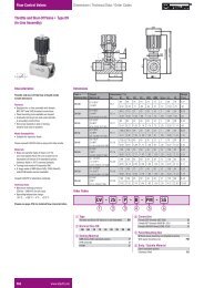
<strong>Electronic</strong> <strong>Feedback</strong> Cylinder Design FeaturesABHLT II Transducer• Corrosion-resistant stainlesssteel transducer is compatiblewith virtually all hydraulicfluids.HLT II <strong>Electronic</strong>s• Encapsulated electronics,housed within the solid steelend cap, provide maximumprotection from shock,vibration damage andexternal elements.EFPiston Seal• O-ring loaded teflon radialseal• Low-friction for positivesealing and smooth actuation• Special seals availablefor lower friction and fluidcompatibilityPiston Wearband• Provides low-friction pistonbearing surface, reducingwear and maximizing lifeGHeavy Duty RodCartridge• Machined from gray iron formaximum bearing supportand wear resistance• Unitized, threadless assemblyis pilot fitted into the headon a precision-bored diameterto assure concentricityCDHLT II Noncontact<strong>Electronic</strong> <strong>Feedback</strong>Magnet• Located in rod thread• Nothing to wear out• No speed limitationLong Life Urethane RodSeals (N5 and HR5)• The Urethane “Ultra-Seal”standard through 8" roddiameters on N5 and HR5cylinders providing the optimumin long life and sealing.• Nitrile lip-type seals arestandard on AN5, LAN5 andR5.• Special seals are availablefor lower friction and fluidcompatibility.BLAEHCFSpecificationsBore Sizes: 1 1 ⁄2" through 30"Media:Air, inert gases and hydraulic fluids.Consult factory for other media.Pressure Ratings: N5 – 3000 psi hydraulic – nominalHR5 – 1500 psi hydraulic – nominalAN5, LAN5 – 250 psi pneumaticTemperature: -40°F to 158°F standardNotes: 1) Mounting styles are NFPA interchangeable for allbore sizes.2) Envelope mounting dimensions are not to NFPAstandard for certain bore and rod size combinations.Refer to the dimensional charts in this brochure andthe respective N5 or R5/A5 catalog for dimensionalinterchangeability.3) HLT II not available in 1 1 ⁄2" bore. Consult factory.I3
HITeflon Tube Seals• Superior design to preventleakage• Compatible with virtually allfluidsPrecision Steel Headsand Caps• Provides truly flat and parallelmounting surfaces• Insures correct alignment oftubing and rod cartridgeJDamage-ResistantPiston Rod• For 1" through 4 1 /2" diameters90,000 to 100,000 minimumpsi yield, case hardened andhard-chrome plated steel isused.• For 5" diameters and above41,000 to 80,000 psi yield,hard-chrome plated steel isused.• All rods are polished to 8-14micro inch finish for long seallife.• 17-4 PH stainless steel Landother materials also available.KDouble-Lipped RodWiper• Nitrile double-lipped rodwiper removes foreign materialsfrom the exposed rod toextend rod-seal life.• The standard rod wiper isnitrile material through 5 1 /2"rod diameter, Viton for 7"through 10" diameter rods.• Metallic rod scraper andlow-friction wipers are alsoavailable.SAE Ports• SAE ports standard on N5and HR5; NPTF ports availableat no extra charge• NPTF ports standard onAN5, LAN5 and R5.• Metric, BSP, Manifold, Flangeand other porting options areavailableDKGJI4
Table Of ContentsHow to Order a Cylinder....................................................page 2Cylinder Design Features.............................................pages 3-4Standard Design Options ................................................. page 5Cylinder Application Data Sheet........................................page 6Sensor Application Data Sheet .........................................page 7How to Order an HLT II Sensor.........................................page 9How to Order an L Series Sensor ...................................page 11How to Order a Balluff BTL-2 Sensor .............................page 13How to Order an RT Sensor............................................page 15Definitions........................................................................page 16Output Specifications for RT ...........................................page 17Output Specifications for HLT II, BTL-2 and L Series .....page 18L Series and BTL-2 Clearance Requirements ................page 19N5 Series Mounting Dimensions..............................pages 22-29N5 Series Oversized Rod Mounting Dimensions.......page 30-31Rod End Styles........................................................pages 31, 47HR5 Series Mounting Dimensions ...........................pages 32-39Technical Data....................................................pages 21, 41-42Cylinder Mounting Accessories ................................pages 43-45Warranty ..........................................................................page 45HR5 Series Oversized Rod Mounting Dimensions ....page 46-47Standard Design OptionsMetallic Rod ScrapersA Metallic Rod Scraper providesincreased rod seal life by removingabrasive contamination from the rodin severe applications.WearbandsBronze-filled Teflon wearband materialreduces friction and wear in applicationswhere side-load is present.Rod BootsA rod boot surrounds the piston rodwith an external, expandable coverto protect the rod surface from externalcontamination. Requires additionalrod length which is determined bythe cylinder stroke.Low Breakaway PistonA low breakaway piston reducesrunning friction and utilizes abronze-filled Teflon wearband with abi-directional, o-ring energized,bronze-filled Teflon piston seal.1/8" NPTFDrainback PortsDrainback ports are used to returnfluid to the tank that accumulatesbetween the rod seal and rod wiper.Port position No. 1 is standard withalternate locations at 2, 3 and 4. 1 /16"NPTF is standard on 5 /8" and 1"diameter rods. 1 /8" NPTF is standardon larger rod diameters.Air Bleeders1/8" NPTF bleeders are located inthe tube or in the head and capwhen specified. SAE #2 bleederslocated in the head and cap arealso available when specified. Allbleeders may be located in positions1, 2, 3 or 4.Special Rod EndsModifications of standard rod ends or completely special rodend styles are available to meet unique rod end connectionrequirements. (See page 33 for standard rod ends.)Special PortsMetric, BSP, Manifold, Flange and other porting options areavailable to meet specific requirements. (See page 24.)Extra Heavy Chrome Tubes and RodsAdded wear and corrosion resistance are available by specifyingExtra Heavy Chrome (.002" to .003" thick).PlatingElectroless Nickel, Cadmium and other plating finishes areavailable for corrosive, washdown, pharmaceutical, and otherapplications.Stainless Steel Piston RodsPiston rods in 300 and 400 series and 17-4 PH stainless steelare available for those applications requiring increased corrosionresistance.Special Coating and Painting<strong>Cylinders</strong> can be prepared with a primer coat or epoxy, lacquer,or enamel paint finish coatings to customer specifications.Synergistic, Nitrocarburizing and other material treatmentsare also available for special applications.Special MaterialsBronze rod cartridges, complete stainless steel cylinders orother special materials are available to meet most uniquematerial requirements.5
Hydro-Line Application Data SheetCompany Name:Distributor Name:Contact:Contact:Phone Number:Fax Number:Phone Number:Fax Number: ______________QUANTITYModel Numbering SystemSEALS PORT LOCMODEL/SERIES MOUNT BORE STROKE CUSHION ROD DIA ROD STY PORTS ROD PSTN H C MODEL• • •DOUBLE END ADDITIONAL NEEDLE MODELROD STYLE ROD LENGTH LOCATION 4-FLAT PREFIXCCHEAD CAPSTAINLESS STEELSTOP TUBE LENGTH TRUNNION XI DIMENSION ROD TYPEPlease fill in all available information above. Refer to the Hydro-Line Model Numbering System on Pages 2.WHAT IS THE OPERATING ENVIRONMENT?Fluid Media Operating Pressure Temperature at CylinderAir Minimum psi Minimum °FOil Typical psi Typical °FOther Maximum psi Maximum °FFluid TypeWHAT IS THE WORK BEING PERFORMED?Load Rod Speed Cycles per MinutePush lbs. Extend in./sec.Pull lbs. Retract in./sec. (in and out)WHAT IS THE MOUNTING?Attitude Rod End Connection Known Side LoadVertical Angle Horizontal Firmly GuidedDegrees From Vertical Supported lbs.Rod Up Rod Up UnsupportedRod DownRod DownWHAT ENVIRONMENTAL CONDITIONS IS THE CYLINDER SUBJECTED TO?Standard Factory Corrosive Washdown Chemical Outdoors OtherWHAT IS THE PRESENT CYLINDER TYPE AND MODEL NUMBER?WHAT IS THE PRESENT PROBLEM?WHAT INDUSTRY IS THE CYLINDER WHAT TYPE OF MACHINE IS THE WHAT IS THE CYLINDER NAME USEDUSED IN? CYLINDER USED ON? IN THE APPLICATION?APPLICATION SKETCH:DESCRIPTION OF APPLICATIONOR SPECIAL REQUIREMENT:PREPARED BY: DATE: REVIEWED BY: DATE:CUSTOMER DRAWING NUMBER: REVISION DATES: HYDRO-LINE QUOTE NUMBER:6FRM-24-011, 3/97
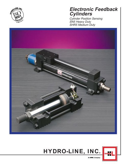
The Hydro-Line HLT IIEncapsulated Linear DisplacementTransducerHydro-Line HLT II linear displacement transducers areprecise, durable, cost-effective alternatives to linear potentiometers.In many applications, they can also replaceLVDTs and linear encoders. Well protected within the coreof the cylinder, the HLT II not only measures the positionof the moving elements of an actuation system, but alsoremains untouched, and unaffected by even the harshestelements. The innovative encapsulated design and engineeringalong with the rugged construction of Hydro-LineHLT II transducers guarantee the best reliability, precisionand durability in even the toughest industrial environments.In addition, problems associated with wear in linearpotentiometers, and cable routing and control in linearencoders are eliminated. Furthermore, HLT II modelsrequire no external signal conditioning. Whether positionsensing requirements are simple or complex, the Hydro-Line HLT II will help find solutions in a form factor andmounting configuration that fits any application.Improved DesignAs a leader in actuation products, Hydro-Line hasenhanced the design of the HLT II to deliver superior accuracyin linear displacement technology. The cylinder’scapabilities have been increased with a longer displacementrange (up to 142") and smaller non-linearity (±.02%).Absolute rather than incremental output eliminates theneed for re-homing in power-down situations. A non-contactsensing element virtually eliminates the wear, noiseand erroneous signal problems inherent in other linear displacementsensing devices.The HLT II transducer is available in either analog or digitalformat. Tighter precision, along with a higher operatingtemperature (now 185° F) and faster response time,make the Hydro-Line HLT II an ideal solution for a widerange of industrial applications requiring strict motion control.SpecificationsCharacteristicDescription/SpecificationSupply Voltage 24 Vdc ±20% or ±15 Vdc ±2% or ±12 Vdc ±2%Current Draw≤90 mA (≤1A inrush)Displacement Range2" to 142" strokeOutput Update≤1msNon-Linearity ±0.02%RepeatabilityResolution + HysteresisHysteresis < 0.00004"ResolutionAnalog: InfinitePulse: Defined by controlShock Rating100g /11ms (single hit)Vibration Rating12g (10 to 2,000Hz)Operating Pressure*3000 psi continuous, 8000 psi staticOperating Temperature-40 to 185°F (-40 to 85°C)Protection for Micro-Change NEMA 6P; IP68 (when cable is mated to connector)Connector and Cable AssemblyWashdown Pressure1000 psi (when cable is mated to connector)Molded Cable Assembly22 AWG, PVC insulated, metallic braid, fine stranded copper conductors, yellow PVCjacketed, 300 V, 3 amp, 105°C U.L. recognized, C.S.A. certifiedOutputsAnalog: 0 to +10Vdc, -10 to +10 Vdc , -5 to +5 Vdc, 4 to 20 mA, 0 to 20 mA( All analog outputs can be forward and reverse acting)Analog Adjustability: 15% adjustment of full scaleDigital: RS422 Start/Stop (leading or trailing edge active)Pulse-Width Modulated(Internal or External Interrogation with 2,4,6 or 8 recirculations)Maximum Cable LengthAnalog: Voltage output 50 feet, Current output 500 feetDigital: 1600 feetSpecifications are subject to change without notice. Contact Hydro-Line for verification of specifications critical to your requirements.* Compare these specifications to cylinder specifications. Use the proper limiting specifications.8
How to Order an HLT II1-A-1-A-2-N-0-HSymbol Feature Description1 Sensor Type Hydro-Line In-Cylinder Sensor (HLT II)Analog OutputA0 to +10 VdcB0 to +10 Vdc, Reverse ActingC4 to 20 mAD4 to 20 mA, Reverse ActingE0 to 20 mAOutputF0 to 20 mA, Reverse ActingOptionsGReference -10 to +10 VdcHPage 18 -10 to +10 Vdc, Reverse ActingJ-5 to +5 VdcK-5 to +5 Vdc Reverse ActingDigital OutputPPWM (Pulse Width Modulation) -specify internal or external interrogation and 2, 4, 6 or 8 recirculationsRRS422 (Start/Stop leading edge active)SRS422 (Start/Stop trailing edge active)1 Power Requirement 24 Vdc (±20%)2 Reference ± 15 Vdc (±2%)3 Page 8 ±12 Vdc (±2%)AStraight Micro Change Cable Assembly, 6 FootBStraight Micro Change Cable Assembly,12 FootCStraight Micro Change Cable Assembly, 20 FootDRight Angle Micro Change Cable Assembly, 6 FootERight Angle Micro Change Cable Assembly, 12 FootFRight Angle Micro Change Cable Assembly, 20 FootJ Mating CableOptionsStraight Micro Change Cable Assembly, Special Length Cable(<strong>Electronic</strong> <strong>Feedback</strong> Application Data Sheet Required)KSee belowRight Angle Micro Change Cable Assembly, Special Length Cable(<strong>Electronic</strong> <strong>Feedback</strong> Application Data Sheet Required)NNo Cable AssemblyXSpecial Connector and Cable (<strong>Electronic</strong> <strong>Feedback</strong> Application Data Sheet Required)1 Position 1Connector2 Position 2Location3 Position 3Reference4 Page 20 or 40 Position 4XSpecial Location (<strong>Electronic</strong> <strong>Feedback</strong> Application Data Sheet Required)H Supplier Supplied by Hydro-Line0 No Manifold Block1 Valve Mounting Pattern 12 Manifold Mounting Pattern 23StyleDO5 Mounting PatternReference4 Page 42 DO3 Mounting PatternXSpecial Valve Patterns (<strong>Electronic</strong> <strong>Feedback</strong> Application Data Sheet Required)N Sensor Cover Not applicableAnalog or Digital HLT II <strong>Electronic</strong>s ModuleNonferrous Plug AssemblyPermanent MagnetStraight CableAssemblyMolded Cable Assembly1.60"2.50"90° CableAssemblyNOTE: 90° CableAssembly PositionNot AdjustableIntegral or Nonintegral CoverSix Pin Mirco-Change Connector9
Transducer Specifications – Temposonics L SeriesNoncontact TransducerHydro-Line utilizes MTS Temposonics ® feedback technology, a magnetostriction device. Selection of feedback outputshould be matched to the control systems to ensure optimum performance of the positioning system.SpecificationsCharacteristicDescription/SpecificationSupply Voltage Strokes < 60"; +13.5 to 26.4 Vdc (±0%); Strokes >60"; + 24Vdc (±10%)Current DrawAnalog: 120 mADigital: 100 mA TypicalNull SpaceNull space is 2" unless otherwise notedDead BandDead band is 2.5" from tip of transducerDisplacement Range Analog: 1" to 78" strokeDigital: 1" to 120" strokeHead EnclosureAluminum die-cast head, IP 67 stainless rod and flangeNon-Linearity± 0.02% or ± 0.0002", whichever is greaterRepeatability±0.001% of full stroke or ± 0.0001", whichever is greaterHysteresis0.0008" maximumResolutionAnalog: InfiniteDigital: 1÷ [gradient x Crystal Freg. (mHz) x circulation]; Max resolution: 0.00025"EMC Test*DIN EN 50081-1 (Emissions)DIN EN 50082-2 (Immunity)Operating Temperature -40°F to 158°FOperating Pressure ** 3000 psi continuous, 5000 psi static, 10,000 psi spikeShock Rating100g (single hit) / IEC standard 68-2-27 (survivability)Update TimeAnalog: < 1msDigital: Resolution and Stroke dependent; Minimum = [Stroke (specified in inches) + 3] x 9.1 µsOutput (absolute) Analog: Voltage and current output available – see L Series ordering guideAnalog Adjustability: Field adjustable zero and span to 5% of active strokeDigital: Pulse-width modulated (up to 15 recirculations); Start/Stop (RS422 compatible)Vibration Rating 5g/10-150 Hz/IEC standard 68-2-6Maximum Cable Length Analog: 50 feetDigital: PWM output, 150 feetRS422 Start/Stop 500 feet* EMC test specification does not include sensor with the RB connection style. Sensor with RB connection style meets the following standard: DIN EN50081-2 (emissions) and DIN EN 50082-1 (immunity).** Compare these specifications to cylinder specifications. Use the proper limiting specification.Temposonics ® is a registered trademark of MTS System Corporation10
How to Order a Temposonics L Series5-A-1-A-0-A-0-HSymbol Feature Description5 Sensor Type Temposonics L SeriesABCDEFXPR0 to +10 Vdc0 to +10 Vdc, Reverse Acting4 to 20 mA4 to 20 mA, Reverse Acting0 to 20 mA0 to 20 mA, Reverse ActingSpecial Analog Output (<strong>Electronic</strong> <strong>Feedback</strong> Application Data Sheet Required)Digital OutputDPM Module, Pulse Width Modulation (<strong>Electronic</strong> <strong>Feedback</strong> Application Data Sheet Required)RPM Module, RS422 Start/StopVSpecial Digital Output (<strong>Electronic</strong> <strong>Feedback</strong> Application Data Sheet Required)1 Power Requirement +13.5 to 26.4 Vdc (±0%); Strokes < 60"Reference Page 10 + 24Vdc ±10%; Strokes >60"ABCDEFGHJKLMNPRSTWXStraight 7 Pin Molded Micro Connector 5 FootStraight 7 Pin Molded Micro Connector 15 FootStraight 7 Pin Molded Micro Connector 25 FootRight Angle 7 Pin Molded Micro Connector 5 FootRight Angle 7 Pin Molded Micro Connector 15 FootRight Angle 7 Pin Molded Micro Connector 25 Foot10 Pin Molded Threaded Connector 5 Foot10 Pin Molded Threaded Connector 15 Foot10 Pin Molded Threaded Connector 25 FootIntegral 5 footIntegral 15 footIntegral 25 foot0 No Cover1 Cover Position 1Connector2 Position 2Location3 Reference Position 34 Page 20 or 40 Position 4XHBStraight 7 Pin Molded Micro Connector, Special LengthRight Angle 7 Pin Molded Micro Connector, Special Length10 Pin Molded Threaded Connector Special Length10 Pin Molded Threaded Connector Only, Transducer Side, No Cable Assembly7 Pin Micro Connector Only, Transducer Side, No Cable Assembly10 Pin Threaded Connector with mating Cable Connector Only. No Cable AttachedSpecial Connector And CableSpecial Location (<strong>Electronic</strong> <strong>Feedback</strong> Application Data Sheet Required)Supplied By Hydro-LineCustomer to Supply, Hydro-Line to Install (<strong>Electronic</strong> <strong>Feedback</strong> Application Data Sheet Required)CCustomer to Supply and Install (<strong>Electronic</strong> <strong>Feedback</strong> Application Data Sheet Required)0 No Manifold Block1 Valve Mounting Pattern 12ManifoldMounting Pattern 2Style3 DO5 Mounting PatternReference4 Page 42 DO3 Mounting PatternXSpecial Valve Patterns (<strong>Electronic</strong> <strong>Feedback</strong> Application Data Sheet Required)ANo CoverBCDEXOutputOptionsReferencePage 18SensorConnectorandMatingCableOptionsReferencePage 19SupplierSensorCoverReferencePage 19With Strain ReliefWith MS ConnectorProtective Cover with Strain ReliefProtective Cover with MS ConnectorSpecial Configuration (<strong>Electronic</strong> <strong>Feedback</strong> Application Data Sheet Required)Temposonics II, III and intrinsically safe options are also available; consultHydro-Line for details.11
Transducer Specifications – Balluff BTL-2 ®Noncontact TransducerThe BTL-2 utilizes magnetostriction technology. Balluffoffers a transducer design for rugged industrial environmentswherever linear motion must be controlled. Two standardtypes of feedback outputs are available: analog and digital.Selection of feedback output should be matched to thecontrol systems to ensure optimum performance of thepositioning system.SpecificationsCharacteristicDescription/SpecificationSupply Voltage +24 Vdc ± 10% or ±15 Vdc ± 2%Current DrawAnalog: 130 mA @ +24 Vdc, 100/50 mA @ ±15 VdcDigital: Differential Start/Stop version; 110 mA @ 24 VdcAll Others: 35 mA @ 24 VdcDisplacement Range 2" to 140" strokeNull SpaceNull space is 2" unless otherwise notedDead BandDead band is 2.36" from tip of transducerNon-Linearity± 0.01 “ @ ≤ 20" stroke± 0.03% of full scale @ > 20" strokeRepeatabilityResolution + HysteresisHysteresis≤0.00008"ResolutionAnalog: 0.1 mVdc; voltage outputs< 1.0 µAdc; current outputsDigital: Defined by controlTemperature Coefficient 20 ppm/°COperating Temperature -13°F to 176°F (-25°C to 80°C)Operating Pressure* 3000 psi continuous; 8700 psi staticProtection Class IP67, NEMA 6Sampling RateAnalog: 1.0 KHz (per update)Digital: 2,800 m/sec./length (maximum)Shock Rating50g (single hit)Vibration Rating 6g (10 to 150 Hz)Housing Material Anodized aluminumRod Material Stainless steel 304Maximum Cable Length 50 feet Voltage output500 feet Current output1500 feet Pulse outputOutputsAnalog: Voltage and current output available – see BTL-2 Series ordering guideAnalog Adjustability: Null – minimum ± 3 /8"; maximum up to 10% of total stroke or ±2", whichever is smallerFull Scale – ±2% of total strokeVelocity (optional): 0 to ±10 Vdc, polarity of output defines direction of travel(4 to 20 mA velocity is also available)Digital: TTL level, nominal 0 and 5 V, true high, parallel transmission*Compare these specifications to cylinder specifications. Use the proper limiting specification.BTL-2 ® is a registered trademark of Balluff Inc.12
How to Order a Balluff BTL-2 ® 133-A-1-A-0-A-0-HSymbol Feature Description3 Sensor Type Balluff Transducer (BTL-2)A0 to +10VdcB0 to +10Vdc, Reverse ActingC-5 to +5VdcD-5 to +5Vdc, Reverse ActingE-10 to +10VdcF-10 to +10Vdc, Reverse ActingG0 to 20mA**H0 to 20mA, Reverse Acting**J Output 4 to 20mA**KOptions4 to 20mA, Reverse Acting**ReferenceX Page 18 Special Analog Output (<strong>Electronic</strong> <strong>Feedback</strong> Application Data Sheet Required)*Digital OutputLStart/Stop with Three StateMDifferential Stop – Leading Edge ActiveNDifferential Pulse Width ModulatedPDifferential Start/Stop – Leading Edge ActiveRSingle Ended Start/Stop – Leading Edge ActiveSDifferential Start/Stop – Trailing Edge ActiveTDifferential Pulse Width Recirculated (<strong>Electronic</strong> <strong>Feedback</strong> Application Data Sheet Required)VSpecial Digital Output (<strong>Electronic</strong> <strong>Feedback</strong> Application Data Sheet Required)1 Power Requirement +24Vdc ±10%2 Reference Page 12 ±15 Vdc ±2%ACable Out Assembly, 3 meterBCable Out Assembly, 5 meterCCable Out Assembly, 10 meterDStraight Connector Cable Assembly, 3 meterE Sensor Straight Connector Cable Assembly, 5 meterF Connector Straight Connector Cable Assembly, 10 meterG and Right Angle Connector Cable Assembly, 3 meterH Mating Right Angle Connector Cable Assembly, 5 meterJ Cable Right Angle Connector Cable Assembly, 10 meterK Options Straight Connector Only, No CableL Reference Right Angle Connector Only, No CablePage 19MNo Cable AssemblyNCable Out Assembly, Special Length Cable (<strong>Electronic</strong> <strong>Feedback</strong> Application Data Sheet Required)PStraight Connector Cable Assembly, Special Length (<strong>Electronic</strong> <strong>Feedback</strong> Application Data Sheet Required)RRight Angle Connector Cable Assembly, Special Length (<strong>Electronic</strong> <strong>Feedback</strong> Application Data Sheet Required)XSpecial Connector And Cable (<strong>Electronic</strong> <strong>Feedback</strong> Application Data Sheet Required)0 No CoverCover1 Position 1Connector2LocationPosition 23 Reference Position 34 Page 20 or 40 Position 4XSpecial Location (<strong>Electronic</strong> <strong>Feedback</strong> Application Data Sheet Required)HSupplied By Hydro-LineB Supplier Customer to Supply, Hydro-Line to Install (<strong>Electronic</strong> <strong>Feedback</strong> Application Data Sheet Required)CCustomer to Supply and Install (<strong>Electronic</strong> <strong>Feedback</strong> Application Data Sheet Required)0 No Manifold Block1 Valve Mounting Pattern 12 Manifold Mounting Pattern 2Style3 DO5 Mounting PatternReference4 Page 42 DO3 Mounting PatternXSpecial Valve Patterns (<strong>Electronic</strong> <strong>Feedback</strong> Application Data Sheet Required)ANo CoverBWith Strain ReliefC Sensor Cover With Threaded MS ConnectorReferenceDProtective Cover with Strain ReliefPage 19EProtective Cover with Threaded MS ConnectorXSpecial Configuration (<strong>Electronic</strong> <strong>Feedback</strong> Application Data Sheet Required)* Velocity output available upon customer request, specify on <strong>Electronic</strong> <strong>Feedback</strong> Application Data Sheet.** Available in ungrounded conditioning, specify on <strong>Electronic</strong> <strong>Feedback</strong> Application Data Sheet.
Transducer Specifications – RTContact Type TransducerLinear Potentiometer – Method of OperationsThe linear potentiometer device is rigidly attached to thecap end of the cylinder and runs the full stroke lengthinside a gun drilled piston rod. The transducer consists ofa hardened aluminum extrusion in a shallow channelframe shape. A resistive plastic substrate material is bondedto one side of the channel and a conductive plastic substrateto the opposite side. A sliding wiper contact assembly isattached to the cylinder piston. As the piston rod movesthrough the stroke, the contacts conduct variable voltagechanges from the resistive side to the conductive side.Application DescriptionsThis type of transducer provides accurate position feedbackfor low cycle, slow moving applications. When used inhydraulic applications, the transducer electric propertiesare dependent on nonconductive, noncontaminated operatingfluids while the mechanical properties are dependent onnonvolatile, noncorrosive operating fluids. When used inpneumatic applications, the transducer depends on properair filtration and drying to prevent contact wiper contamination.Avoid ‘slick’ type seal lubricants. The transducer mountingarrangement discourages infield repair. Duplicate cylinderswith this transducer are recommended for spares if theapplication requires immediate turnaround.Molded Cable AssemblyResistive Strip TransducerPressure Tight ConnectorWiper AssemblyTransducer Length = Stroke + 2 / "Straight CableAssembly3 81.60"2.50"90° CableAssemblyNOTE: 90° CableAssembly PositionNot AdjustableSpecificationsCharacteristicDescription/SpecificationSupply Voltage+5 Vdc to +50 Vdc, bipolar or unipolarCurrent Draw1 microAmp maximumDisplacement Range1" to 130", 1 ⁄8" incrementsNon-Linearity0.1% (1" to 46" stroke); 1.0% (47" to 130" stroke)Repeatability 0.001"Operating Temperature* 300°FOperating Pressure*5000 psi maximumTransducer Life500 million inches of travelCylinder Velocity20 in/sec maximum hydraulic; 50 in/sec maximum pneumaticProtection for Pressure Connectorand Cable AssemblyNEMA 6P; IP68 (when cable is mated to pressure connector)Washdown Pressure1000 psi (when cable is mated to pressure connector)Molded Cable Assembly22 AWG: DVC insulated, metallic braid fine stranded copper conductors, yellow PVCjacketed, 300 V, 3 amp, 105°C U.L. recognized, C.S.A. certifiedMaximum Cable Lengthfrom Cylinder to Signal20 feetConditioning <strong>Electronic</strong>sMaximum Cable Length from 20 feet Voltage outputSignal Conditioning to User End 100 feet Current outputOutputRatiometric*Compare these specifications to cylinder specifications. Use the proper limiting specification.14
How to Order an RTSymbol Feature Description4 Sensor Type Resistive Transducer (RT)ANo Conditioning Module4-A-1-A-2-N-0-HBCDAnalog Output, Scalable Module0 to +10 Vdc-10 to +10 Vdc4 to 20 mAOutputOptionsConditioningAnalog Output, Nonscalable ModuleModuleEDual Set Point Relay, Standard Potentiometer AdjustmentReferenceFPage 17 Dual Set Point Transistor, Standard Potentiometer AdjustmentGDual Set Point Triac, Standard Potentiometer AdjustmentHDual Set Point Relay, Precision Potentiometer AdjustmentJDual Set Point Transistor, Precision Potentiometer AdjustmentKDual Set Point Triac, Precision Potentiometer AdjustmentXSpecial Analog Output (<strong>Electronic</strong> <strong>Feedback</strong> Application Data Sheet Required)1 Power No Conditioning Module2 Requirement +15 Vdc for Nonscalable Output Modules only3 Conditioning ± 15 Vdc for Scalable Output Modules only4 Modules 115 Vac for Either Type ModuleX Reference Page 17 Power requirement for special analog outputAStraight Micro Change Cable Assembly, 6 FootBStraight Micro Change Cable Assembly, 12 FootCStraight Micro Change Cable Assembly, 20 FootDMatingRight Angle Micro Change Cable Assembly, 6 FootECableRight Angle Micro Change Cable Assembly, 12 FootOptionsFRight Angle Micro Change Cable Assembly, 20 FootReferenceJPage 14 Straight Micro Change Cable Assembly, Special Length Cable(<strong>Electronic</strong> <strong>Feedback</strong> Application Data Sheet Required)KRight Angle Micro Change Cable Assembly, Special Length Cable(<strong>Electronic</strong> <strong>Feedback</strong> Application Data Sheet Required)NNo Cable AssemblyXSpecial Connector and Cable (<strong>Electronic</strong> <strong>Feedback</strong> Application Data Sheet Required)1 Position 1Connector2 Position 2Location3 Position 3Reference4 Page 20 or 40 Position 4XSpecial Location (<strong>Electronic</strong> <strong>Feedback</strong> Application Data Sheet Required)H Supplier Supplied By Hydro-Line0 No Manifold BlockValve1 Mounting Pattern 1Manifold2StyleMounting Pattern 23 Reference DO5 Mounting Pattern4 Page 42 DO3 Mounting PatternXSpecial Valve Patterns (<strong>Electronic</strong> <strong>Feedback</strong> Application Data Sheet Required)N Sensor Cover Not ApplicableLinear Potentiometer Equivalent Circuit15
DefinitionsAnalog Output – Voltage outputmeasured on an absolutescale that is relative to theposition of the external magneticsource. The analog outputscale goes from 0 to 10 Vdc,or from 10 to 0 Vdc. This versionis self-interrogating.Pulse Width Output – Theduration of the output pulse isproportional to position. A digitalcounter card can be used toconvert this output signal intoa Binary Coded Decimal(BCD) or Natural Binary output.Start/Stop – The outputof the Start/Stop signalis compatible withRS422 output levels.The interrogation signalis a differential pulse,1 µsecond wide.ExternalInterrogationTimingTransducer + GateOutput– GateAnalog Output(0 to 10 Vdc or 10 to 0 Vdc)Pulse WidthModulated OutputUpdateTimeUserDefinedStart/Stop Outputs(with RS422 compatible signal levels)Resolution – The smallest increment stroke that can be detectedand indicated in an output. In a digital system, the theoretical resolutionof the transducer’s sensing element is less than .001 inches. Theactual resolution of a system is a direct function of oscillating frequencyin the circuitry responsible for counting or timing. Units for resolutionare normally given as inches or millimeters per count. For example,at any length, 28 MHz yields a .004 inches/count resolution,whereas 56 MHz yields a .002 inches/count resolution. The sensitivityand design of the receiver’s electronics and external wiring limitthe resolution of analog outputs.Gradient – The rate at which magnetostrictive pulses travelthrough the waveguide. This figure is about 9.05 µsec. per inch(0.356 µsec. per millimeter), but will vary slightly from one transducerto the next.Update Time – The minimum time interval between interrogationsignals. To calculate the update time for Start/Stop units, use thefollowing formula:Update Time (in milliseconds) = (S) (G) (2)whereS = Maximum stroke length (e.g., active stroke in inchesplus 2.62 inches, or active stroke in millimeters plus66.5 millimeters.G = Gradient (Gradient = approximately 0.00905 for Englishsystem of measurement, or 0.000356 for metric system)Non Linearity – Maximum deviation of a measured input/outputcurve which plots measured displacement versus actual displacement.Expressed in a + or – percent of deviation of full scale.Hysteresis – The potential difference in indicated position for thesame point along a stroke length when reached from oppositedirections. Repeatability defines the potential difference in indicatedposition for the same point when repeatedly reached from thesame direction.Approach #1Approach #2It is important to note thehysteresis specification Stroke LengthPoint Afor position sensors issignificantly less than resolution and can, in most applications,be ignored.Repeatability – The deviation in output value when a point alonga stroke length is repeatedly approached from the same direction.Example: Read theApproach #1output value as youarrive at point A from aApproach #2particular direction. Ifyou leave position A Stroke Lengthand then return to itPoint Afrom the same direction as before, the potential change in outputvalue from the two readings is described by the repeatabilityspecification.Temperature Coefficient (TC) – The degree to which the outputsignal (e.g., the indicated position) is affected by ambient temperaturechanges. Expressed as parts per million/°F or °C.Example (analog output sensor):• Output: 0 to 10 Vdc• Stroke Length: 10 inches• Temperature Change: 10°CIf the output at 10 inches is 10 Vdc, the potential change in outputper degree Centigrade temperature change is ≤0.0008 V(0.00008 x 10) or a total of 8 mV for a 10°C rise.Asynchronous Operation/Internal Interrogation – Defines asystem which consists of a pulse width modulated transducerand a customer supplied digital counter card or high speedcounter. The transducer generates an internal interrogation signalat a fixed frequency. The frequency is determined by the strokelength and the number of recirculations.Synchronous Operation/External Interrogation – In digitalsystems, this defines a system which consists of a pulse widthmodulated transducer using a customer generated or externalinterrogation pulse. This is a complex method of interrogationthat requires special user-designed hardware and detailedknowledge of the sensor technology.Recirculations (circulations) – In digital systems, a processthat improves resolution of an LDT system. The on time of thepulse duration signal is multiplied by a specified factor (2 to 127).This provides more counting time for the counter, improving resolution.The process involves retriggering an interrogation pulse a fixednumber of times.Recirculations = 1 ÷ (G x F x R)whereG = Gradient (approximately 9.05 µs per inch or .356 µs permillimeter)F = Crystal frequency of the counterR = Resolution (in inches or millimeters)4-20 mA Output – Grounded versus UngroundedUngrounded Output: If this output is grounded, the output willfail. The negative (return) line of the output is isolated from thepower supply common and cannot be connected to the powersupply common or to the power supply positive. In many installationsyou will find that the receiver device input is grounded to thesame earth ground that the power supply common is groundedto. This would effectively connect the return to power supplycommon and the units will not function.Grounded Output: This output uses the supply common as thereturn and is, therefore, “grounded” since it is recommended thatthe user ground the power supply common to earth ground.16
Output Specifications – RT and Signal Conditioning ModulesRatiometric OutputA ratiometric sensor output is directly proportional to the input source voltage. The user can take advantage of this by‘trimming’ the sensor output to his specific needs by adjusting the input source voltage.Scalable Analog Output ControllerThis controller offers the user a scalable output that can be measured by a meter, PLC or other device. Available outputsare 0 Vdc to 10 Vdc, -10 Vdc to 10 Vdc and 4 mA to 20 mA. Supply voltage to the controller can be DC or AC. The unitsoutput is scalable over the stroke of the cylinder providing full scale linear output between two points, whether end ofstroke or points in between.Nonscalable Dual Set Point ControllerThis controller offers the user infinitely adjustable, dual trip points anywhere along the stroke of the cylinder. Thecontroller is available with 2-Triac, 2-relay or 2-transistor type outputs. Controllers are equipped with either a single turnset-point potentiometer or an optional multi-turn potentiometer for applications that require more resolution.Dual Set Point ControllerInfinitely adjustable within cylinder strokeScalable Analog Output ControllerFor continuous position outputSpecificationsCharacteristicDescription/SpecificationEnclosure Dimensions3" High x 5 5 /8" Wide x 4 5 /16" DeepMounting Holes3 9 /16" by 4 7 /8" center to center, 4 placesShipping Weight2 lbs.Power Input Requirements AC (All Units): 115 V, 60 Hz, .1 AmpDC (Set Point Systems): +15 Vdc, .1 AmpDC (Indicator Systems): +15 Vdc and -15 Vdc, 40 mA each supply4 to 20 mA System: +15 Vdc and -15 Vdc, 50 mA each supplyInput Fuse.250 AmpOutput Specification – Set Point Relay (2): 3 Amp @ 28 Vdc, 5 Amp @ 115 VdcTriac (2): 2 Amp (60-115 Vac)Transistor (2): 10 mAOutput Specifications – Analog Output 0 to 10 V, 1 mA maximum output current (10K ohm impedance minimum)-5 to +5, -10 to +10 V, 1 mA maximum output current (10K ohm impedance minimum)4 to 20 mA, into 500 ohm maximum impedanceMaximum Zero Offset: 50% of cylinder strokeMaximum Span Range: 50% of cylinder stroke<strong>Electronic</strong>s Operating Temperature 40°F to 130°F17
Output Specifications – HLT II, BLT-2 and Temposonics L SeriesAnalog Output OptionsAnalog Systems include a Linear DisplacementTransducer, a magnet and the cable between the sensorand the customer electronics. The sensor generatesthe interrogation pulse, senses the return pulse anddevelops the analog output displacement signal (voltageor current). The HLT II has all of the electronicsencased inside the cap of the cylinder.Digital Output OptionsThere are three digital output options available. Each providesa different type of digital output, either pulse widthmodulation, binary (natural binary or binary coded decimal)or an RS422 Start/Stop pulse output.MagnetPower Supply Requirements:• +24 Vdc, ±15 Vdc or ±12 Vdc for HLT II and BLT-2• 13.5 to 28 Vdc for Temposonics L SeriesT1Analog Displacement OutputT21) The digital PWM electronics are self contained inthe transducer. The interrogation electronics providea pulse width modulated TTL level output (noexternal signal conditioning required).Power Supply Requirements:• +24 Vdc, ±15 Vdc or ±12 Vdc for HLT II and BLT-2• 13.5 to 28 Vdc for Temposonics L SeriesPulse Width OutputUser’sControlSystem2) The PWM output, in conjunction with an externallymounted digital counter card, provides naturalbinary (18 bits) or BCD (4 1 /4 digits) output (usingtwo counter cards would provided the capabilityto achieve 22 bit natural binary and 6 BCD outputs).Power Supply Requirements:• +24 Vdc, ±15 Vdc or ±12 Vdc for HLT II and BLT-2• 13.5 to 28 Vdc for Temposonics L Series+2.5 V0+2.5 V0Pulse Duration OutputDigitalCounterCardNatural Binaryor BCD Output+5 Vdc3) The RS422 output electronics are self containedin the transducer. A customer supplied 1 KHzsquare wave signal is required with this outputoption to produce an RS422 Start/Stop output.Power Supply Requirements:• +24 Vdc, ±15 Vdc or ±12 Vdc for HLT II and BLT-2• 13.5 to 28 Vdc for Temposonics L SeriesUser’sControlSystem1µs18
Temposonics L and Balluff BTL-2 Clearance RequirementsTransducer and Connector Without a Cover OptionBore Rod C-409-X “OH”Dia. Dia. R5 N51.50 1.00 N/A 1/42.001.00 3/41/41.38 3/41/41.00 3/41/42.50 1.38 3/41/41.75 3/41/43.254.005.006.008.00OHCAPOJOCOAOKOETemposonics L and Balluff BTL-2 C-409-XClearance AdderStandard RodDiameter forEach BoreStandard RodDiameter forEach Bore1/21/4OGN/AN/ACover Option with MS or Strain Relief ConnectorOBBalluff BTL-2Sensor andConnectorAnalogBTL-2w/ S32AnalogBTL-2w/ S33DigitalBTL-2w/ S32DigitalBTL-2w/ S33AnalogBTL-2w/Cable OutDigitalBTL-2w/Cable OutOA OB OC OE OG7.30See OCand OE5.90See OCand OETemposonics L Series––Sensor andConnectorAnalog/DigitalTemposonics L Series2.092.092.092.092.092.09OJ2.634.334.332.952.954.332.95OKSeeBelow2.441.462.441.461.10.50OK connector Dimensions (includes cable bend)• Straight 7 pin molded Micro Connector with mating Connector. 3.38 in• Right angle 7 pin molded Micro Connector with mating Connector. 2.15 in• 10 pin molded threaded Connector with mating Connector. 4.30 in• Integral cable out. 2.75 in–2.66–2.66––3.50"3.50"3.50" Analog(Transducer)4.00" Digital2.50"7.33"R5 2" Bore Tube, Cap and Tie RodsRegardless of Cylinder Model or Bore Size6.00" J KProtective CoverHard CoverContinuous Tie Rod19
N5 Cylinder Port Size Data and Location InformationPortsStandard ports for N5 and WBN5 are SAE straightthread. AN5 and LAN5 standard ports are NPTF.Optional and Oversize PortsThe chart at right lists port sizes. Larger welded half-pipecoupling ports are available in some sizes; pleasecontact Hydro-Line.Port LocationsStandard port locations are at No. 1, with optional locationsNo. 2, 3 or 4 furnished when specified, except whereH, U or W mounts interfere at No. 2 and 4. Ports at No.3 in B and the cap end of E mountings need specialconstruction. Note possible piping interference withmounting screws in A cylinders ported at No. 2 and 4.Mounting holes are counterbored to allow access tothem with piping in place. Request Engineering File P-26for reference to dimensions.Cylinder RodBore Dia. DiameterStd.SAE*OversizeHeadCapStd.1 1 /2 1 #10 N/A N/A 1/2 N/A 3/4 N/A 9/162 1 #10 N/A N/A 1/23/43/4 N/A 9/161 3 /8 #10 N/A N/A 1/2 N/A 3/4 N/A 9/162 1 /2 1 #10 N/A N/A 1/21 3 /8 #10 N/A N/A 1/2NPTFOversizeHead1 3 /4 #10 N/A N/A 1/2 N/A 3/4 N/A 9/163 1 /4 1 3 /8 #12 #16 #16 3/4 1 1 3/41 3 /4 #12 #16 #16 3/4 1 1 3/42 #12 #16 #16 3/4 1 1 3/44 1 3 /4 #12 #16 #16 3/4 1 1 3/43/43/4Cap2 #12 #16 #16 3/4 1 1 3/42 1 /2 #12 #16 #16 3/4 1 1 3/45 2 #12 #16 #16 3/4 1 1 3/43/43/44-BoltSAE**2 1 /2 #12 #16 #16 3/4 1 1 3/43 #12 #16 #16 3/4 1 1 3/43 1 /2 #12 #16 #16 3/4 1 1 3/41/21/2Manifold***6 2 1 /2 #16 N/A #20 1 1 1 /4 1 1 /4 1 13 #16 N/A #20 1 1 1 /4 1 1 /4 1 13 1 /2 #16 N/A #20 1 1 1 /4 1 1 /4 1 14 #16 N/A #20 1 1 1 /4 1 1 /4 1 19/169/163/43/43/43/43/43/43/43/43/43/47 3 #20 #24 #24 1 1 /4 1 1 /2 1 1 /2 1 1 /4 1 3 /83 1 /2 #20 #24 #24 1 1 /4 1 1 /2 1 1 /2 1 1 /4 1 3 /84 #20 #24 #24 1 1 /4 1 1 /2 1 1 /2 1 1 /4 1 3 /84 1 /2 #20 #24 #24 1 1 /4 1 1 /2 1 1 /2 1 1 /4 1 3 /85 #20 #24 #24 1 1 /4 1 1 /2 1 1 /2 1 1 /4 1 3 /88 3 1 /2 #24 N/A N/A 1 1 /2 2 2 1 1 /2 1 5 /84 #24 N/A N/A 1 1 /2 2 2 1 1 /2 1 5 /84 1 /2 #24 N/A N/A 1 1 /2 2 2 1 1 /2 1 5 /85 #24 N/A N/A 1 1 /2 2 2 1 1 /2 1 5 /85 1 /2 #24 N/A N/A 1 1 /2 2 2 1 1 /2 1 5 /8* Fitting hex may interfere with mountings S, R and P.Consult factory for additional information.** Flanges may overhang head and caps.Consult factory for additional information.*** Manifold dimension is for flow passage diameter.Locations 1 through 4 indicate possible port positions.Number 1 is standard.N5 Systems Cylinder Pressure RatingsCylinderBoreDia. (in.)Design Pressure RatingsPiston Rod Dia. (in.)Non/Cap Cushion Both/Head CushionStd. Oversize Area 2:1 4:1 Tensile 4:1 Yield 4:1 Tensile 4:1 Yield1 1 /2 1 N/A 1 3750* 3005* N/A N/A2 1 N/A 1 3 /8 2900 2335 1890 15752 1 /2 1 1 3 /8 1 3 /4 2120 1765 1155 9603 1 /4 1 3 /8 1 3 /4 2 3050 2475 1890 15754 1 3 /4 2 2 1 /2 3050 2440 3050 24405 2 2 1 /2, 3 3 1 /2 3270 2615 3270 26156 2 1 /2 3, 3 1 /2 4 2770 2220 2770 22207 3 3 1 /2, 4, 4 1 /2 5 2690 2155 2690 21558 3 1 /2 4, 4 1 /2, 5 5 1 /2 2810 2245 2810 2245* Only available in noncushion design20
Hydro-Line Technical DataPressure-Thrust-Consumption-Flow ChartsCyl.BoreininchesAirAN5LAN5Standard OperatingPressure RatingHyd.N5AirLR5R5Hyd.HR5PistonAreasq. in.50psi60psi80psi100psiOut-Stroke Thrust In Pounds ForcePressures of Operating Medium – Air or Hydraulic200psi250psi500psi750psi1000psi1500psi2000psi3000psiConsumption Per InchOf Stroke in One DirectionOilGallonsDisplacedAirPressureCubic Ft.DisplacedFree AirCubic Ft.at 80 psiDisplaced1 1 /222 1 /23 1 /445678250 3000 200 1500 1.84 92 110 147 184 368 460 920 1,380 1,840 2,760 3,680 5,520 .00797 .00106 .00683250 2900 200 1500 3.24 162 194 259 324 648 810 1,620 2,430 3,240 4,860 6,480 9,720 .01403 .00188 .01211250 2120 200 1500 5.03 252 302 402 503 1,006 1,258 2,520 3,773 5,030 7,545 10,060 15,090 .02177 .00291 .01875250 3000 200 1185 8.45 423 507 676 845 1,690 2,113 4,230 6,338 8,450 12,675 16,900 25,350 .03658 .00489 .03149250 3000 200 770 12.76 638 766 1,021 1,276 2,552 3,190 6,380 9,570 12,760 19,140 25,520 38,280 .05524 .00738 .04755250 3000 200 485 19.87 994 1,192 1,590 1,987 3,974 4,968 9,940 14,903 19,870 29,805 39,740 59,610 .08602 .01150 .07405250 2770 200 960 28.56 1,428 1,714 2,285 2,856 5,712 7,140 14,280 21,420 28,560 42,840 57,120 85,680 .12364 .01653 .10644250 2690 200 N/A 38.82 1,941 2,329 3,106 3,882 7,764 9,705 19,410 29,115 38,820 58,230 77,640 116,460 .16805 .02247 .14468250 2810 200 530 50.64 2,532 3,038 4,051 5,064 10,128 12,660 25,320 37,980 50,640 75,960 101,280 151,920 .21922 .02931 .18873PistonRodDia. ininchesBoreSizeN5AN5LAN5BoreSizeR5LR5HR5PistonRodAreasq. in. 50psiIn-stroke pull in pounds forceDeduct the following force or consumptions corresponding to rod size fromout-stroke thrust or consumptions to determine in-stroke pull or consumptions.Pressures of Operating Medium – Air or Hydraulic60psi80psi100psi200psi250psi500psi750psi1000psi1500psi2000psi3000psiConsumption Per InchOf Stroke in One DirectionOilGallonsDisplacedAirPressureCubic Ft.DisplacedFree AirCubic Ft.at 80 psiDisplaced1 1 1 /2 1, 1 1 /2, 2, 2 1 /2 .79 40 47 63 79 158 198 395 593 790 1,185 1,580 2,370 .00138 .00018 .001161 2 & 2 1 /2 3 1 /4, 4, 5 .79 40 47 63 79 158 198 395 593 790 1,185 1,580 2,370 .00342 .00046 .002941 3 /8 3 1 /4 6, 8 1.49 75 89 119 149 298 373 745 1,118 1,490 2.235 2,980 4,470 .00645 .00086 .005551 3 /4 4 2.41 121 145 193 241 482 603 1,205 1,808 2,410 3,615 4,820 7,230 .01043 .00139 .008982 5 3.14 157 188 251 314 628 785 1,570 2,355 3,140 4,710 6,280 9,420 .01359 .00182 .011702 1 /2 6 4.91 246 295 393 491 982 1,228 2,455 3,683 4,910 7,365 9,820 14,730 .02126 .00284 .018303 7 7.07 354 424 566 707 1,414 1,768 3,535 5,303 7,070 10,605 14,140 21,210 .03061 .00409 .026353 1 /2 8 9.62 481 577 770 962 1,924 2,405 4,810 7,215 9,620 14,430 19,240 28,860 .04165 .00557 .03585NOTE: Bore dimensions are 0.030" larger than NOMINAL.Above are cylinder sizes for which the rod diameters in the column to the left are standard. Consult factory for rods larger than standard. Thrusts for pressures notshown in table, add the thrust for two or more operating pressures which combined equal the desired pressure.Pipe Size Chart for Hydraulic <strong>Cylinders</strong> and SystemsStandard Weight PipePipeSizeInsideDiameter*AreaSq. In.Oil Flow Gallons Per Minute And Friction Pressure Drop Pounds Per Square Inch Per Foot Length Of PipeVel. = 5 Ft. Per Sec. Vel. = 10 Ft. Per Sec. Vel. = 15 Ft. Per Sec. Vel. = 20 Ft. Per Sec. Vel. = 25 Ft. Per Sec. Vel. = 30 Ft. Per Sec.GallonsperMinutePressureDrop inpsiGallonsperMinutePressureDrop inpsiGallonsperMinutePressureDrop inpsi1/2 .622 .304 4.7 .157 9.4 .585 14.1 1.215 18.6 2.065 23.5 3.130 28.2 4.343/4 .824 .533 8.3 .117 16.6 .370 24.9 .710 33.2 1.520 41.5 2.300 49.8 3.171 1.049 .864 13.5 .090 26.9 .323 40.4 .673 53.8 1.555 67.3 1.725 80.8 2.441 1 /4 1.380 1.495 23.3 .064 46.5 .231 69.8 .488 93.0 .755 116.3 1.240 139.6 1.741 1 /2 1.610 2.036 31.7 .054 63.4 .181 95.1 .404 126.8 .691 158.5 1.042 190.2 1.482 2.067 3.355 52.3 .047 104.5 .169 156.8 .360 209.0 .609 261.3 .927 313.6 1.11GallonsperMinutePressureDrop inpsiGallonsperMinutePressureDrop inpsiGallonsperMinutePressureDrop inpsiStandard Weight PipePipeSizeInsideDiameter*AreaSq. In.Std.ElbowEquivalent Length of StraightPipe in Feet for Various Fitting<strong>Cylinders</strong>Std. Gate Globe& 2-3-WayTee Valve ValveValves4-WayValves1/2 .622 .304 1.5 3.3 .35 17 6 to 30 12 to 603/4 .824 .533 2.2 4.5 .47 22 10 to 50 20 to 1001 1.049 .864 2.7 5.8 .60 28 13 to 65 25 to 1251 1 /4 1.380 1.495 3.7 7.7 .81 37 15 to 75 30 to 1501 1 /2 1.610 2.036 4.4 9.2 .92 44 20 to 100 40 to 2002 2.067 3.355 5.5 12.0 1.20 57 25 to 125 50 to 250* Inside diameter and areas shown are standard pipe. For tubing or extra heavyand double extra heavy pipe, use I.D. in table closest to your pipe or tubing I.D.The pressure drop shown in the above table is for ordinary wroughtiron pipe. For smooth, new wrought iron pipes, multiply the valuesshown by .7; for very smooth, straight tubing, multiply the valuesshown by .54. Pressure drop is the same regardless of operatingpressure. Avoid large pressure drops in low pressure systems. Notethat oil flows through large pipes at high velocity (up to 30 ft. persec.) with small pressure loss. The pressure drop shown is forhydraulic oil with approximately 225 SSU at 100°F under averageoperating conditions. The values also apply to water. In order toaccommodate large pump volumes without severe pressure drops,all Hydro-Line hydraulic cylinders are available with oversize portswith welded half pipe couplings or flange fitting.1 Gallon = 231 Cubic InchesOil consumption gal. per min = Gal. per in X in. per min. piston speedAir consumption cubic ft. per min = Cu. ft. per in X in. piston speedFree air consumption per in. of stroke = Cu. ft. displaced X (press. + 14.7) ÷ 14.721
N5 Series Mounting Dimensions1 1 /2" - 8" bore cylinders✠ ✾ ♠❍RM1EE (2)KKRODDIA.MMY•P• ★RODDIA.MMKKY•KP• ★RM1EE (2)42RR2 43DFLATSBE SQTFUFFB‡AC VBFHWG J KLB ★ZB ★ACVFG J FHLB ★ZF ★FB‡3DFLATSBE SQTFUF3 1 /4"- 8" bores available for L Series/BTL-2.NOTE: Possible mounting restrictions at Position 5.N5F – Head Rectangular Flange Mount (NFPA Style MF1)N5R – Cap Rectangular Flange Mount (NFPA Style MF2)✠ ✾ ♠❍RMEE (2)1 RODDIA.MMKKY•P• ★RODDIA.MMKKY•KP• ★RM1EE (2)42R2 4R3DFLATSBE SQTFUFFB‡ACVFWFG J KLB ★ZB ★ACVFGLB ★ZJ ★J3DFLATSBESQTFUF.3 1 /4"- 8" bores available for L Series/BTL-2.NOTE: Possible mounting restrictions at Position 5.FB‡22N5G – Head Rectangular Mount (NFPA Style ME5)MOUNTING G ONLYNOTE: Use the chart below for the cartridge retainer platedimensions for the bore and rod combinations listed.See page 11 for all other mounting dimensions.4Bore1 1 /222 1 /23 1 /413RMDIA.RodDia.5/82RARef.C11/32 – 2 3 /81 1/2 2.44 2 5 /81 1/2 – 2 5 /819/32 2.94 3 1 /41 3 /81 3 /81 3 /41 3 /4F RA RM V19/32 – 3 1 /419/32 3.44 3 7 /819/32 – 3 7 /8FV9/323/83/813/3213/3217/3217/32219/32 – 417/32N5P – Cap Rectangular Mount (NFPA Style ME6)Maximum Operating Pressures in psifor F Mounting in PushCYLINDER STANDARD ROD 2:1 PISTON RODBORE Heavy Duty Nonshock Heavy Duty Nonshock5 & 6 1440 2400 1120 18407 1040 1760 720 12008 800 1350 640 1120Maximum Operating Pressures in psifor R Mounting in PullCYLINDER STANDARD ROD 2:1 PISTON RODBORE Heavy Duty Nonshock Heavy Duty Nonshock5 & 6 1800 3000 1400 23007 1300 2200 900 15008 1000 1700 800 1400NOTE: When pressure must exceed the limitations abovefor mountings F and R, specify J or S mounting.(Up to a maximum of 3000 psi heavy duty, 5000 psinonshock.)
Cylinder DimensionsBORE 1 1 /2 2 2 1 /2 3 1 /4 4 5 6 7 8A 1 1 /8 1 1 /8 1 1 /8 1 5 /8 2 2 1 /4 3 3 1 /2 3 1 /2AA 2.3 2.9 3.6 4.6 5.4 7.0 8.1 9.3 10.6B -.001-.003C1 1 /21/21 1 /21/21 1 /21/225/82 3 /83/42 5 /87/83 1 /813 3 /414 1 /41CC 1/2-20 7 /8-14 7 /8-14 1 1 /4-12 1 1 /2-12 1 3 /4-12 2 1 /4-12 2 3 /4-12 3 1 /4-12D 7/8 7/8 7/8 1 1 /8 1 1 /2 1 3 /4 2 1 /8 2 5 /8 3E 2 1 /2 3 3 1 /2 4 1 /2 5 6 1 /2 7 1 /2 8 1 /2 9 1 /2EE (SAE) 10 10 10 12 12 12 16 20 24EE (NPTF) 1/2 1/2 1/2 3/4 3/4 3/4 1 1 1 /4 1 1 /2F ▲ ▲ 1/2 19/32 19/32 19/32 19/32 23/32 23/32FB‡ 7/16 9/16 9/16 11/16 11/16 15/16 1 1 /16 1 3 /16 1 5 /16FH 3/8 5/8 5/8 3/4 7/8 7/8 1 1 1FT 5/8-18 1-14 1-14 1 3 /8-12 1 3 /4-12 2-12 2 1 /2-12 3-12 3 1 /2-12G 1 3 /4 1 3 /4 1 3 /4 2 2 2 2 1 /4 2 3 /4 3K 3/8 7/16 7/16 9/16 9/16 13/16 15/16 1 1 1 /8KK 3/4-16 3 /4-16 3 /4-16 1-14 1 1 /4-12 1 1 /2-12 1 7 /8-12 2 1 /4-12 2 1 /2-12MM 1 1 1 1 3 /8 1 3 /4 2 2 1 /2 3 3 1 /2R 1.63 2.05 2.55 3.25 3.82 4.95 5.73 6.58 7.50RM ■ ■ 2 5 /8 3 1 /4 3 7 /8 4 4 7 /16 5 1 /4 5 5 /8TF 3 7 /16 4 1 /8 4 5 /8 5 7 /8 6 3 /8 8 3 /16 9 7 /16 10 5 /8 11 13 /16UF 4 1 /4 5 1 /8 5 5 /8 7 1 /8 7 5 /8 9 3 /4 11 1 /4 12 5 /8 14V ▲ ▲ 3/8 13/32 17/32 17/32 21/32 17/32 17/32VB 1/2 1/4 1/4 1/4 1/4 1/4 1/4 1/4 1/4W 1 3/4 3/4 7/8 1 1 1 /8 1 1 /4 1 1 /4 1 1 /4WF 1 3 /8 1 3 /8 1 3 /8 1 5 /8 1 7 /8 2 2 1 /4 2 1 /4 2 1 /4Y• 2 15 /32 2 15 /32 2 15 /32 2 23 /32 2 31 /32 3 3 /32 3 19 /32 3 15 /16 4 1 /16LB + StrokeJJJ<strong>Electronic</strong> <strong>Feedback</strong> CylinderDimensional ChangesBORE 1 1 /2 2 2 1 /2 3 1 /4 4 5 6 8C HLT II – 7/8 7/8 3/4 9/16 3/16 ¬ ¬** L Series/BTL-2 ¬ ¬ ¬ ¬ ¬ ¬ ¬ ¬RT ¬ ¬ ¬ ¬ ¬ ¬ ¬ ¬**Style 4 rod ends may require additional rod length. The following dimensions willincrease by the C dimension in the above chart: C, SE, W, WF, XC, XD, XE, XG,XJ, XS, XT, Y, ZB, ZE, ZF, ZJ and ZT.J HLT II – 2 1 /4 2 1 /8 2 2 2 2 1 /4 2 3 /4 3L Series/BTL-2 1 1 /2 1 1 /2 1 1 /2 1 3 /4 1 3 /4 1 3 /4 2 1 /4 2 3 /4 3RT 1 1 /2 1 1 /2 1 1 /2 1 3 /4 1 3 /4 1 3 /4 2 1 /4 2 3 /4 3JJ◆ HLT II – 3/8 3/8 3/8 3/8 3/8 3/8 3/8 3/8LB★ HLT II – 5 3 /8 5 3 /8 5 3 /4 6 6 1 /2 7 3 /8 8 1 /2 9 1 /2L Series/BTL-2 5 1 /2 5 1 /2 5 5 /8 5 1 /2 5 3 /4 6 1 /4 7 3 /8 8 1 /2 9 1 /2RT 5 5 /8 5 5 /8 5 3 /4 5 1 /2 5 3 /4 6 1 /4 7 3 /8 8 1 /2 9 1 /2P•★ HLT II – 2 11 /16 2 13 /16 3 9 /16 3 13 /16 4 5 /16 4 11 /16 5 1 /8 5 7 /8L Series/BTL-2 3 9 /16 3 9 /16 3 11 /16 3 9 /16 3 13 /16 4 5 /16 4 11 /16 5 1 /8 5 7 /8RT 3 11 /16 3 11 /16 3 13 /16 3 9 /16 3 13 /16 4 5 /16 4 11 /16 5 1 /8 5 7 /8ZB★ HLT II – 7 9 /16 7 3 /16 7 15 /16 8 7 /16 9 5 /16 10 9 /16 11 3 /4 12 7 /8L Series/BTL-2 7 1 /4 7 5 /16 7 7 /16 7 11 /16 8 3 /16 9 1 /16 10 9 /16 11 3 /4 12 7 /8RT 7 3 /8 7 7 /16 7 9 /16 7 11 /16 8 3 /16 9 1 /16 10 9 /16 11 3 /4 12 7 /8ZF★ HLT II – 7 3 /8 7 3 /8 8 1 /8 8 3 /4 9 3 /8 10 5 /8 11 3 /4 12 3 /4L Series/BTL-2 7 1 /4 7 1 /2 7 5 /8 7 7 /8 8 1 /2 9 1 /8 10 5 /8 11 3 /4 12 3 /4RT 7 3 /8 7 5 /8 7 3 /4 7 7 /8 8 1 /2 9 1 /8 10 5 /8 11 3 /4 12 3 /4ZJ★ HLT II – 6 3 /4 6 3 /4 7 3 /8 7 7 /8 8 1 /2 9 5 /8 10 3 /4 11 3 /4L Series/BTL-2 6 7 /8 6 7 /8 7 7 1 /8 7 5 /8 8 1 /4 9 5 /8 10 3 /4 11 3 /4RT 7 7 7 1 /8 7 1 /8 7 5 /8 8 1 /4 9 5 /8 10 3 /4 11 3 /4Dimensions shown in purple are mounting dimensions.NOTE: To determine piston thickness, subtract G and J dimensions from LBdimension.NOTE: Additional port information on page 20.Oversize rods affect dimensions in gray-shaded areas.See pages 30-31for these dimensions.★ Add stroke to all starred dimensions.■ Requires full front square retainer.NOTE: Overall length dimensions that require addition of stroke may vary fromdimensions shown, due to manufacturing tolerances.▲ Use FH dimension in place of F dimension and VB dimension in place of Vdimension.◆ The JJ dimension is the cover plate thicknessfor the HLT II electonics. A squarecover plate is required on the 2" bore size while all others receive a circular type.‡ Use screws 1 ⁄16" smaller than mounting holes.• Port dimensions for standard ports only. Consult Hydro-Line for flange, manifoldand special ports.¬ No additional C required for a Style 4 rod end.CCLB + StrokeRefer to ordering code on pages 9, 11, 13 and 15:✠ Sensor cover not available for 1 1 ⁄2" bore.✾ A, B & C sensor cover options available for 2" bore.❖ A, B & C sensor cover options available for 2" and 2 1 ⁄2" bore.❚ A, B & C sensor cover options available for 2"-3 1 ⁄4" bore.∞ A, B & C sensor cover options available for 2"-8" bore.✧ B & C sensor cover options available for 2"-8" bore.♠ All sensor cover options available for 2 1 ⁄2"-8" bores.❍ All sensor cover options available for 3 1 ⁄4"-8" bores.Ω All sensor cover options available for 4"-8" bores.NOTE: Consult factory on applications requiring cushionsor bores over 8".NOTE: Consult factory on applications requiring 1 1 ⁄2" bore HLT II.23
N5 Series Mounting DimensionsKK❍RODDIA.MMY•KP• ★RMEE (2)12 4RTF✠ ✾ ♠ A and BMounts ❚ Ω E MountRM1EE (2)RODDIA.MMKKY•P• ★ACVFGLB ★ZF ★JFH3DFLATSBRE SQTFUF SQFB‡423DFLATSBE SQA-.013FH -.015CWVBGFH2ZB ★ LB★JK3 1 /4"- 8" bores available for L Series/BTL-2.NOTE: Possible mounting restrictions at Position 5.N5S – Cap Square Flange Mount (NFPA Style MF6)NOTE: To order, specify extended key plate after the N5 series andmounting style. (Example: N5A with extended key plate)N5 – Extended Key Plate – Available when specified✠ ✾ ♠✠ ✾ ♠RM1EE (2)RODDIA.MMKKY•P• ★RMB1EE (2)RODDIA.MM KKY•P• ★423DFLATSBRE SQTFUF SQRTFFB‡ACVBFHWGLB ★ZB ★JK43DFLATSTNE SQ2TKE -.0052 -.010NT TAPACVFXTGSN ★LB ★ZB ★2 1 /2"- 8" bores available for L Series/BTL-2.JKN5J – Head Square Flange Mount (NFPA Style MF5)N5B – Side Tapped Mount (NFPA Style MS4)4✠ ✾ ♠RM13DFLATSBRE SQK and MMountsEE (2)2AARODDIA.MMKK∞ABBL and N Mounts not available in1 1 /2" bore for L Series/BTL-2Y•CVBFHWGP• ★LB ★ZT ★N5K – No tie rods extendedN5L – Tie rods extended both endsN5M – Tie rods extended head endN5N – Tie rods extended cap endNOTE: Possible mounting restrictions at Position 5 for L and N Mounts.NOTE: Mounting styles L and M use filler plate at the head end whencylinder has circular retainer.N5K (No Mount), N5L (NFPA Style MX1), N5N (NFPA Style MX2),N5M (NFPA Style MX3) – Tie Rods Extended MountsJKBBDD❚ ΩEG4DIA. COUNTERBOREEF 2 HOLES HEAD END ONLYRMEE (2)13DFLATSBBLE SQ2E -.0052 -.010ETRODDIA.MMKKEB‡1/64 APPROX.AY•CVBFHWN5E – Side End Lugs Mount (NFPA Style MS7)GZE ★ XE ★P• ★KEOJ ELLB ★SE ★3 1 /4"- 8" bores available for L Series/BTL-2.NOTE: Bottoms of heads and caps are mounting surfaces. Lugshold cylinders against mounting surface.NOTE: Port at Position 3 not available on 1 1 /2" -4" bore.NOTE: Possible restrictions on mounting dimensions on small bores.24
Cylinder DimensionsBORE 1 1 /2 2 2 1 /2 3 1 /4 4 5 6 7 8A 1 1 /8 1 1 /8 1 1 /8 1 5 /8 2 2 1 /4 3 3 1 /2 3 1 /2AA 2.3 2.9 3.6 4.6 5.4 7.0 8.1 9.3 10.6B -.001-.003BB1 1 /21 3 /81 1 /21 13 /161 1 /21 13 /1622 5 /162 3 /82 5 /162 5 /83 3 /163 1 /83 5 /83 3 /44 1 /84 1 /44 1 /2C 1/2 1/2 1/2 5/8 3/4 7/8 1 1 1CC 1/2-20 7 /8-14 7 /8-14 1 1 /4-12 1 1 /2-12 1 3 /4-12 2 1 /4-12 2 3 /4-12 3 1 /4-12D 7/8 7/8 7/8 1 1 /8 1 1 /2 1 3 /4 2 1 /8 2 5 /8 3DD 3/8-24 1 /2-20 1 /2-20 5 /8-18 5 /8-18 7 /8-14 1-14 1 1 /8-12 1 1 /4-12E 2 1 /2 3 3 1 /2 4 1 /2 5 6 1 /2 7 1 /2 8 1 /2 9 1 /2EE (SAE) 10 10 10 12 12 12 16 20 24EE (NPTF) 1/2 1/2 1/2 3/4 3/4 3/4 1 1 1 /4 1 1 /2EF 5 /813 /1613 /16 1 1 1 3 /8 1 5 /8 1 5 /8 2 3 /32EG 11 /163 /43 /4 1 1 /167 /8 1 1 /4 1 1 /2 1 1 /2 1 3 /4EL 7 /815 /1615 /16 1 1 /8 1 1 /8 1 1 /2 1 11 /16 1 13 /16 2EO 3 /81 /21 /25 /85 /83 /47 /8 1 1 1 /8ET 7 /8 1 1 1 1 /4 1 1 /4 1 1 /2 1 3 /4 2 2F ▲ ▲ 1/2 19/32 19/32 19/32 19/32 23/32 23/32FB‡ 7/16 9/16 9/16 11/16 11/16 15/16 1 1 /16 1 3 /16 1 5 /16FH 3/8 5/8 5/8 3/4 7/8 7/8 1 1 1FT 5/8-18 1-14 1-14 1 3 /8-12 1 3 /4-12 2-12 2 1 /2-12 3-12 3 1 /2-12G 1 3 /4 1 3 /4 1 3 /4 2 2 2 2 1 /4 2 3 /4 3K 3/8 7/16 7/16 9/16 9/16 13/16 15/16 1 1 1 /8KK 3/4-16 3 /4-16 3 /4-16 1-14 1 1 /4-12 1 1 /2-12 1 7 /8-12 2 1 /4-12 2 1 /2-12MM 1 1 1 1 3 /8 1 3 /4 2 2 1 /2 3 3 1 /2NT 3/8-16 1 /2-13 5 /8-11 3 /4-10 1-8 1-8 1 1 /4-7 1 1 /2-6 1 1 /2-6R 1.63 2.05 2.55 3.25 3.82 4.95 5.73 6.58 7.50RM ■ ■ 2 5 /8 3 1 /4 3 7 /8 4 4 7 /16 5 1 /4 5 5 /8TF 3 7 /16 4 1 /8 4 5 /8 5 7 /8 6 3 /8 8 3 /16 9 7 /16 10 5 /8 11 13 /16TK 9/16 1/2 13/16 3/4 1 1 1 /8 1 5 /16 2 1 /8 1 9 /16TN 3/4 15/16 1 5 /16 1 1 /2 2 1 /16 2 15 /16 3 5 /16 3 3 /4 4 1 /4UF 4 1 /4 5 1 /8 5 5 /8 7 1 /8 7 5 /8 9 3 /4 11 1 /4 12 5 /8 14V ▲ ▲ 3/8 13/32 17/32 17/32 21/32 17/32 17/32VB 1/2 1/4 1/4 1/4 1/4 1/4 1/4 1/4 1/4W 1 3/4 3/4 7/8 1 1 1 /8 1 1 /4 1 1 /4 1 1 /4XT 2 2 3 /8 2 3 /8 2 3 /4 3 3 1 /8 3 1 /2 3 13 /16 3 15 /16Y• 2 15 /32 2 15 /32 2 15 /32 2 23 /32 2 31 /32 3 3 /32 3 19 /32 3 15 /16 4 1 /16LB + StrokeJJJ<strong>Electronic</strong> <strong>Feedback</strong> CylinderDimensional ChangesBORE 1 1 /2 2 2 1 /2 3 1 /4 4 5 6 8C HLT II – 7/8 7/8 3/4 9/16 3/16 ¬ ¬** L Series/BTL-2 ¬ ¬ ¬ ¬ ¬ ¬ ¬ ¬RT ¬ ¬ ¬ ¬ ¬ ¬ ¬ ¬**Style 4 rod ends may require additional rod length. The following dimensions willincrease by the C dimension in the above chart: C, SE, W, WF, XC, XD, XE, XG,XJ, XS, XT, Y, ZB, ZE, ZF, ZJ and ZT.J HLT II – 2 1 /4 2 1 /8 2 2 2 2 1 /4 2 3 /4 3L Series/BTL-2 1 1 /2 1 1 /2 1 1 /2 1 3 /4 1 3 /4 1 3 /4 2 1 /4 2 3 /4 3RT 1 1 /2 1 1 /2 1 1 /2 1 3 /4 1 3 /4 1 3 /4 2 1 /4 2 3 /4 3JJ◆ HLT II – 3/8 3/8 3/8 3/8 3/8 3/8 3/8 3/8LB★ HLT II – 5 3 /8 5 3 /8 5 3 /4 6 6 1 /2 7 3 /8 8 1 /2 9 1 /2L Series/BTL-2 5 1 /2 5 1 /2 5 5 /8 5 1 /2 5 3 /4 6 1 /4 7 3 /8 8 1 /2 9 1 /2RT 5 5 /8 5 5 /8 5 3 /4 5 1 /2 5 3 /4 6 1 /4 7 3 /8 8 1 /2 9 1 /2P•★ HLT II – 2 11 /16 2 13 /16 3 9 /16 3 13 /16 4 5 /16 4 11 /16 5 1 /8 5 7 /8L Series/BTL-2 3 9 /16 3 9 /16 3 11 /16 3 9 /16 3 13 /16 4 5 /16 4 11 /16 5 1 /8 5 7 /8RT 3 11 /16 3 11 /16 3 13 /16 3 9 /16 3 13 /16 4 5 /16 4 11 /16 5 1 /8 5 7 /8SE★ HLT II – 8 1 /4 7 7 /8 8 3 /4 9 1 /8 10 3 /8 11 3 /4 13 1 /8 14 1 /2L Series/BTL-2 7 5 /8 8 8 8 1 /2 8 7 /8 10 1 /8 11 3 /4 13 1 /8 14 1 /2RT 7 3 /4 8 1 /8 8 1 /4 8 1 /2 8 7 /8 10 1 /8 11 3 /4 13 1 /8 14 1 /2SN★ HLT II – 2 7 /8 3 3 1 /2 3 3 /4 4 1 /4 5 1 /8 5 7 /8 6 5 /8L Series/BTL-2 3 3 /4 3 3 /4 3 7 /8 3 1 /2 3 3 /4 4 1 /4 5 1 /8 5 7 /8 6 5 /8RT 3 7 /8 3 7 /8 4 3 1 /2 3 3 /4 4 1 /4 5 1 /8 5 7 /8 6 5 /8XE★ HLT II – 8 1 /16 7 11 /16 8 1 /2 9 10 11 5 /16 12 9 /16 13 3 /4L Series/BTL-2 N/A 7 13 /16 7 15 /16 8 1 /4 8 3 /4 9 3 /4 11 5 /16 12 9 /16 13 3 /4RT 7 7 /8 7 15 /16 8 1 /16 8 1 /4 8 3 /4 9 3 /4 11 5 /16 12 9 /16 13 3 /4ZB★ HLT II – 7 9 /16 7 3 /16 7 15 /16 8 7 /16 9 5 /16 10 9 /16 11 3 /4 12 7 /8L Series/BTL-2 7 1 /4 7 5 /16 7 7 /16 7 11 /16 8 3 /16 9 1 /16 10 9 /16 11 3 /4 12 7 /8RT 7 3 /8 7 7 /16 7 9 /16 7 11 /16 8 3 /16 9 1 /16 10 9 /16 11 3 /4 12 7 /8ZE★ HLT II – 8 9 /16 8 3 /16 9 1 /8 9 5 /8 10 3 /4 12 3 /16 13 9 /16 14 7 /8L Series/BTL-2 N/A 8 5 /16 8 7 /16 8 7 /8 9 3 /8 10 1 /2 12 3 /16 13 9 /16 14 7 /8RT 8 1 /4 8 7 /16 8 9 /16 8 7 /8 9 3 /8 10 1 /2 12 3 /16 13 9 /16 14 7 /8ZF★ HLT II – 7 3 /8 7 3 /8 8 1 /8 8 3 /4 9 3 /8 10 5 /8 11 3 /4 12 3 /4L Series/BTL-2 7 1 /4 7 1 /2 7 5 /8 7 7 /8 8 1 /2 9 1 /8 10 5 /8 11 3 /4 12 3 /4RT 7 3 /8 7 5 /8 7 3 /4 7 7 /8 8 1 /2 9 1 /8 10 5 /8 11 3 /4 12 3 /4ZT★ HLT II – 8 15 /16 8 9 /16 9 11 /16 10 3 /16 11 11 /16 13 1 /4 14 7 /8 16 1 /4L Series/BTL-2 8 1 /4 8 11 /16 8 13 /16 9 7 /16 9 15 /16 11 7 /16 13 1 /4 14 7 /8 16 1 /4RT 8 3 /8 8 13 /16 8 15 /16 9 7 /16 9 15 /16 11 7 /16 13 1 /4 14 7 /8 16 1 /4Dimensions shown in purple are mounting dimensions.NOTE: To determine piston thickness, subtract G and J dimensions from LBdimension.NOTE: Additional port information on page 20.Oversize rods affect dimensions in gray-shaded areas.See pages 30-31 for these dimensions.★ Add stroke to all starred dimensions.■ Requires full front square retainer.NOTE: Overall length dimensions that require addition of stroke may vary fromdimensions shown, due to manufacturing tolerances.▲ Use FH dimension in place of F dimension and VB dimension in place of Vdimension.◆ The JJ dimension is the cover plate thickness for the HLT II electonics. A squarecover plate is required on the 2" bore size while all others receive a circular type.‡ Use screws 1 ⁄16" smaller than mounting holes.• Port dimensions for standard ports only. Consult Hydro-Line for flange, manifoldand special ports.¬ No additional C required for a Style 4 rod end.CCLB + StrokeRefer to ordering code on pages 9, 11, 13 and 15:✠ Sensor cover not available for 1 1 ⁄2" bore.✾ A, B & C sensor cover options available for 2" bore.❖ A, B & C sensor cover options available for 2" and 2 1 ⁄2" bore.❚ A, B & C sensor cover options available for 2"-3 1 ⁄4" bore.∞ A, B & C sensor cover options available for 2"-8" bore.✧ B & C sensor cover options available for 2"-8" bore.♠ All sensor cover options available for 2 1 ⁄2"-8" bores.❍ All sensor cover options available for 3 1 ⁄4"-8" bores.Ω All sensor cover options available for 4"-8" bores.NOTE: Consult factory on applications requiring cushionsor bores over 8".NOTE: Consult factory on applications requiring 1 1 ⁄2" bore HLT II.25
N5 Series Mounting Dimensions1 1 /2" - 8" bore cylinders✠ ✾ ♠✠ ✾ ♠RM1EE (2)RODDIA.MM KKY•P• ★RM1EE (2)RODDIA.MMKKY•P• ★43DFLATSBE SQTSUS2E -.0052 -.010STSB‡ACVFSWXSGSUSS ★LB ★ZB ★JSUKSW43DFLATSBE SQTSUS2STSB‡ACVFSWXSGSUSS ★LB ★ZB ★JSUKSWN5A – Side Lugs Mount (NFPA Style MS2)N5H – Center-Line Lugs Mount (NFPA Style MS3)RODDIA.MMKKACY•KVFGP• ★RMEE (2)1MRM 2 4 BLRCD25˚*3DFLATSJ L MCWCWLB ★CB†XC ★ E SQKKRODDIA.MMACY•KVFP• ★RMEE (2)1MRM 2 4LRCD25°3DFLATSG J FH L MCWCWLB ★CB†XD ★E SQ✝ Maximum width of mating part.Available with RT only.✝ Maximum width of mating part.Available with HLT II and RT only.N5C – Cap Fixed Clevis MountN5DC – Cap Detachable Clevis Mount (NFPA Style MP2)✧✧MMRODDIAKKAY•P• ★CVF G JLB ★XC ★EELRJCD25°L MMRCW2CB†13D(2) FLATS-.001-.003BRME SQCW4MMRODDIAKKAY•P• ★CVF G JLB ★XD ★EELRJFHCD25°L MMRCW2CB†13D(2) FLATS-.001-.003BRME SQCW4✝ Maximum width of mating part.2" - 8" bores available for L Series and BTL-2 only.N5C – Cap Fixed Clevis Mount✝ Maximum width of mating part.2" - 8" bores available for L Series and BTL-2 only.N5DC – Cap Detachable Clevis Mount (NFPA Style MP2)26
N5 Series Mounting Dimensions1 1 /2" - 8" bore cylinders✠ ✾ ♠✠ ✾ ♠RM1EE (2)RODDIA.MMKKY•P • ★RM1EE (2)RODDIA.MMKKY•P • ★42TD ±.00142TD ±.001TL3DFLATSBE SQUTTLACVFGXJ ★LB ★ZB ★JKTL3DFLATSBE SQUTTLACVFXGGLB ★ZB ★JKN5W – Cap Trunnion Mount (NFPA Style MT2)N5U – Head Trunnion Mount (NFPA Style MT1)✠ ✾ ♠♠TLTMRM1TLEE (2) RODDIA.MMKKY•P • ★BDTLTMRM1TLEE (2)RODDIA.MMKKY•P • ★BDUV 42TD ±.001UV 42TD ±.0013DFLATSBE SQUMAXICVF GCustomer to SpecifyLB ★ZB ★JK3DFLATSBE SQUMAXICVFGCustomer to SpecifyLB ★ZB ★JKNOTE: 1 1 /2" - 5" bores have one-piece trunnion.N5TT – Intermediate Fixed Trunnion Mount (NFPA Style MT4)NOTE: 6" - 8" bores have split trunnion.N5TT – Intermediate Fixed Trunnion Mount (NFPA Style MT4)KKRODDIA.MM✧ACY•KVFGP• ★LUBEFITTING2 4CDNR+.0000-.00053DFLATSJ LEXLB ★XC ★ E SQMaximum Operating Pressure1 1 /2" 2" 2 1 /2" 3 1 /4" 4" 5" 6"1650 2200 1400 1500 1750 1900 1700MSRM1EE (2)3˚3˚MMRODDIAKK✧Y•P• ★ACVF G JLB ★XC ★EENRJLCD+.0000-.0005MS2EX13D(2) FLATSBRM-.001-.003E SQ3°43°2" - 8" bores available for RT only.N5CS – Cap Spherical Bearing MountL Series/BTL-2 only.N5CS – Cap Spherical Bearing Mount28
Cylinder DimensionsBORE 1 1 /2 2 2 1 /2 3 1 /4 4 5 6 7 8A 1 1 /8 1 1 /8 1 1 /8 1 5 /8 2 2 1 /4 3 3 1 /2 3 1 /2B -.001-.0031 1 /2 1 1 /2 1 1 /2 2 2 3 /8 2 5 /8 3 1 /8 3 3 /4 4 1 /4BD 1 1 /2 1 1 /2 1 1 /2 2 2 2 1 /2 3 3 3 1 /2C 1/2 1/2 1/2 5/8 3/4 7/8 1 1 1CC 1/2-20 7 /8-14 7 /8-14 1 1 /4-12 1 1 /2-12 1 3 /4-12 2 1 /4-12 2 3 /4-12 3 1 /4-12CD 1/2 3/4 3/4 1 1 3 /8 1 3 /4 2 2 1 /2 3D 7/8 7/8 7/8 1 1 /8 1 1 /2 1 3 /4 2 1 /8 2 5 /8 3E 2 1 /2 3 3 1 /2 4 1 /2 5 6 1 /2 7 1 /2 8 1 /2 9 1 /2EE (NPTF) 1/2 1/2 1/2 3/4 3/4 3/4 1 1 1 /4 1 1 /2EE (SAE) 10 10 10 12 12 12 16 20 24EX 7/16 21/32 21/32 7/8 1 3 /16 1 17 /32 1 3 /4 – –F ▲ ▲ 1/2 19/32 19/32 19/32 19/32 23/32 23/32FH 3/8 5/8 5/8 3/4 7/8 7/8 1 1 1FT 5 /8-18 1-14 1-14 1 3 /8-12 1 3 /4-12 2-12 2 1 /2-12 3-12 3 1 /2-12G 1 3 /4 1 3 /4 1 3 /4 2 2 2 2 1 /4 2 3 /4 3K 3/8 7/16 7/16 9/16 9/16 13/16 15/16 1 1 1 /8KK 3/4-16 3 /4-16 3 /4-16 1-14 1 1 /4-12 1 1 /2-12 1 7 /8-12 2 1 /4-12 2 1 /2-12L 3/4 1 1 /4 1 1 /4 1 1 /2 2 1 /8 2 1 /4 2 1 /2 3 3 1 /4MM 1 1 1 1 3 /8 1 3 /4 2 2 1 /2 3 3 1 /2MS 15/16 1 3 /8 1 3 /8 1 11 /16 2 7 /16 2 7 /8 3 5 /16 – –NR 5/8 1 1 1 1 /4 1 5 /8 2 1 /16 2 3 /8 – –RM ■ ■ 2 5 /8 3 1 /4 3 7 /8 4 4 7 /16 5 1 /4 5 5 /8TD 1 1 3 /8 1 3 /8 1 3 /4 1 3 /4 1 3 /4 2 2 1 /2 3TL 1 1 3 /8 1 3 /8 1 3 /4 1 3 /4 1 3 /4 2 2 1 /2 3TM 3 3 1 /2 4 5 5 1 /2 7 8 1 /2 9 3 /4 11UM 5 6 1 /4 6 3 /4 8 1 /2 9 10 1 /2 12 1 /2 14 3 /4 17UT 4 1 /2 5 3 /4 6 1 /4 8 8 1 /2 10 11 1 /2 13 1 /2 15 1 /2UV 2 3 /4 3 3 /8 3 7 /8 4 7 /8 5 1 /2 7 1 /4 9 1 /2 11 1 /2 13 1 /4V ▲ ▲ 3/8 13/32 17/32 17/32 21/32 17/32 17/32VB 1/2 1/4 1/4 1/4 1/4 1/4 1/4 1/4 1/43 /47 /8 1 1 1 /8 1 1 /4 1 1 /4 1 1 /4W 1 3 /4XG 2 1 /4 2 1 /4 2 1 /4 2 5 /8 2 7 /8 3 3 3 /8 3 5 /8 3 3 /4Y• 2 15 /32 2 15 /32 2 15 /32 2 23 /32 2 31 /32 3 3 /32 3 19 /32 3 15 /32 4 1 /16LB + StrokeJJJSystem CylinderDimensional ChangesBORE 1 1 /2 2 2 1 /2 3 1 /4 4 5 6 7 8C HLT II – 7/8 7/8 3/4 9/16 3/16 ¬ ¬ ¬** L Series/BTL-2 ¬ ¬ ¬ ¬ ¬ ¬ ¬ ¬ ¬RT ¬ ¬ ¬ ¬ ¬ ¬ ¬ ¬ ¬**Style 4 rod ends may require additional rod length. The following dimensionswill increase by the C dimension in the above chart: C, SE, W, WF, XC, XD, XE,XG, XJ, XS, XT, Y, ZB, ZE, ZF, ZJ and ZT.J HLT II – 2 1 /4 2 1 /8 2 2 2 2 1 /4 2 3 /4 3L Series/BTL-2 1 1 /2 1 1 /2 1 1 /2 1 3 /4 1 3 /4 1 3 /4 2 1 /4 2 3 /4 3RT 1 1 /2 1 1 /2 1 1 /2 1 3 /4 1 3 /4 1 3 /4 2 1 /4 2 3 /4 3JJ◆ HLT II – 3/8 3/8 3/8 3/8 3/8 3/8 3/8 3/8LB★ HLT II – 5 3 /8 5 3 /8 5 3 /4 6 6 1 /2 7 3 /8 8 1 /2 9 1 /2L Series/BTL-2 5 1 /2 5 1 /2* 5 5 /8* 5 1 /2 5 3 /4 6 1 /4 7 3 /8 8 1 /2 9 1 /2RT 5 5 /8 5 5 /8 5 3 /4 5 1 /2 5 3 /4 6 1 /4 7 3 /8 8 1 /2 9 1 /2P•★ HLT II – 2 11 /16 2 13 /16 3 9 /16 3 13 /16 4 5 /16 4 11 /16 5 1 /8 5 7 /8L Series/BTL-2 3 9 /16 3 9 /16 3 11 /16 3 9 /16 3 13 /16 4 5 /16 4 11 /16 5 1 /8 5 7 /8RT 3 11 /16 3 11 /16 3 13 /16 3 9 /16 3 13 /16 4 5 /16 4 11 /16 5 1 /8 5 7 /8XC★ L Series/BTL-2 15 1 /8 15 5 /8 15 3 /4 16 3 /8 17 1 /2 18 1 /4 20 3 /8 22 1 /2 24RT 7 3 /4 8 1 /4 8 3 /8 8 5 /8 9 3 /4 10 1 /2 12 1 /8 13 3 /4 15XJ★ HLT II – 5 1 /4 5 3 /8 6 1 /4 6 3 /4 7 3 /8 8 3 /8 9 3 /8 10 1 /4L Series/BTL-2 6 1 /8 6 1 /8 6 1 /4 6 1 /4 6 3 /4 7 3 /8 8 3 /8 9 3 /8 10 1 /4RT 6 1 /4 6 1 /4 6 3 /8 6 1 /4 6 3 /4 7 3 /8 8 3 /8 9 3 /8 10 1 /4ZB★ HLT II – 7 9 /16 7 3 /16 7 15 /16 8 7 /16 9 5 /16 10 9 /16 11 3 /4 12 7 /8L Series/BTL-2 7 1 /4 7 5 /16 7 7 /16 7 11 /16 8 3 /16 9 1 /16 10 9 /16 11 3 /4 12 7 /8RT 7 3 /8 7 7 /16 7 9 /16 7 11 /16 8 3 /16 9 1 /16 10 9 /16 11 3 /4 12 7 /8Dimensions shown in purple are mounting dimensions.NOTE: To determine piston thickness, subtract G and J dimensions from LBdimension.NOTE: Additional port information on page 20.Oversize rods affect dimensions in gray-shaded areas.See pages 30-31 for these dimensions.★ Add stroke to all starred dimensions.■ Requires full front square retainer.NOTE: Overall length dimensions that require addition of stroke may vary fromdimensions shown, due to manufacturing tolerances.▲ Use FH dimension in place of F dimension and VB dimension in place of Vdimension.◆ The JJ dimension is the cover plate thickness for the HLT II electonics. A squarecover plate is required on the 2" bore size while all others receive a circular type.‡ Use screws 1 ⁄16" smaller than mounting holes.• Port dimensions for standard ports only. Consult Hydro-Line for flange, manifoldand special ports.¬ No additional C required for a Style 4 rod end.Refer to ordering code on pages 9, 11, 13 and 15:✠ Sensor cover not available for 1 1 ⁄2" bore.✾ A, B & C sensor cover options available for 2" bore.❖ A, B & C sensor cover options available for 2" and 2 1 ⁄2" bore.❚ A, B & C sensor cover options available for 2"-3 1 ⁄4" bore.∞ A, B & C sensor cover options available for 2"-8" bore.✧ B & C sensor cover options available for 2"-8" bore.♠ All sensor cover options available for 2 1 ⁄2"-8" bores.❍ All sensor cover options available for 3 1 ⁄4"-8" bores.Ω All sensor cover options available for 4"-8" bores.CCLB + StrokeNOTE: Consult factory on applications requiring cushionsor bores over 8".NOTE: Consult factory on applications requiring 1 1 ⁄2" bore HLT II.29
N5 Oversize Rod InformationThe dimensions listed on these two pages are those that change when oversize rods are used.Bore22 1 /23 1 /445678MM1 3 /8 ▲1 3 /8 ▲1 3 /4 ▲1 3 /42 ▲2 ▲2 1 /2 ▲2 1 /233 1 /2 ▲33 1 /24 ▲3 1 /244 1 /2 ▲5 ▲44 1 /255 1 /2 ▲HLT IILSeries/BTL-2RTHLT IILSeries/BLT-2RTHLT IILSeries/BLT-2RTHLT IILSeries/BLT-2RTHLT IILSeries/BLT-2RTHLT IILSeries/BLT-2RTHLT IILSeries/BLT-2RTHLT IILSeries/BLT-2RTHLT IILSeries/BLT-2RTHLT IILSeries/BLT-2RTHLT IILSeries/BLT-2RTHLT IILSeries/BLT-2RTHLT IILSeries/BLT-2RTHLT IILSeries/BLT-2RTHLT IILSeries/BLT-2RTHLT IILSeries/BLT-2RTHLT IILSeries/BLT-2RTHLT IILSeries/BLT-2RTHLT IILSeries/BLT-2RTHLT IILSeries/BLT-2RTHLT IILSeries/BLT-2RTKK1-141-141-141-141-141-141 1 /4-121 1 /4-121 1 /4-121 1 /4-121 1 /4-121 1 /4-121 1 /2-121 1 /2-121 1 /2-121 1 /2-121 1 /2-121 1 /2-121 7 /8-121 7 /8-121 7 /8-121 7 /8-121 7 /8-121 7 /8-122 1 /4-122 1 /4-122 1 /4-122 1 /2-122 1 /2-122 1 /2-122 1 /4-122 1 /4-122 1 /4-122 1 /2-122 1 /2-122 1 /2-123-123-123-122 1 /2-122 1 /2-122 1 /2-123-123-123-123 1 /4-123 1 /4-123 1 /4-123 1 /2-123 1 /2-123 1 /2-123-123-123-123 1 /4-123 1 /4-123 1 /4-123 1 /2-123 1 /2-123 1 /2-124-124-124-12CC1 1 /4-121 1 /4-121 1 /4-121 1 /4-121 1 /4-121 1 /4-121 1 /2-121 1 /2-121 1 /2-121 1 /2-121 1 /2-121 1 /2-121 3 /4-121 3 /4-121 3 /4-121 3 /4-121 3 /4-121 3 /4-122 1 /4-122 1 /4-122 1 /4-122 1 /4-122 1 /4-122 1 /4-122 3 /4-122 3 /4-122 3 /4-123 1 /4-123 1 /4-123 1 /4-122 3 /4-122 3 /4-122 3 /4-123 1 /4-123 1 /4-123 1 /4-123 3 /4-123 3 /4-123 3 /4-123 1 /4-123 1 /4-123 1 /4-123 3 /4-123 3 /4-123 3 /4-124 1 /4-124 1 /4-124 1 /4-124 3 /4-124 3 /4-124 3 /4-123 3 /4-123 3 /4-123 3 /4-124 1 /4-124 1 /4-124 1 /4-124 3 /4-124 3 /4-124 3 /4-125 1 /4-125 1 /4-125 1 /4-12FT1 3 /8-121 3 /8-121 3 /8-121 3 /8-121 3 /8-121 3 /8-121 3 /4-121 3 /4-121 3 /4-121 3 /4-121 3 /4-121 3 /4-122-122-122-122-122-122-122 1 /2-122 1 /2-122 1 /2-122 1 /2-122 1 /2-122 1 /2-123-123-123-123 1 /2-123 1 /2-123 1 /2-123-123-123-123 1 /2-123 1 /2-123 1 /2-124-124-124-123 1 /2-123 1 /2-123 1 /2-124-124-124-124 1 /2-124 1 /2-124 1 /2-125-125-125-124-124-124-124 1 /2-124 1 /2-124 1 /2-125-125-125-125 1 /2-125 1 /2-125 1 /2-12A1 5 /81 5 /81 5 /81 5 /81 5 /81 5 /82222222 1 /42 1 /42 1 /42 1 /42 1 /42 1 /43333333 1 /23 1 /23 1 /23 1 /23 1 /23 1 /23 1 /23 1 /23 1 /23 1 /23 1 /23 1 /24443 1 /23 1 /23 1 /24444 1 /24 1 /24 1 /25554444 1 /24 1 /24 1 /25555 1 /25 1 /25 1 /2-.001B-.0032222222 3 /82 3 /82 3 /82 3 /82 3 /82 3 /82 5 /82 5 /82 5 /82 5 /82 5 /82 5 /83 1 /83 1 /83 1 /83 1 /83 1 /83 1 /83 3 /43 3 /43 3 /44 1 /44 1 /44 1 /43 3 /43 3 /43 3 /44 1 /44 1 /44 1 /44 3 /44 3 /44 3 /44 1 /44 1 /44 1 /44 3 /44 3 /44 3 /45 1 /45 1 /45 1 /45 3 /45 3 /45 3 /44 3 /44 3 /44 3 /45 1 /45 1 /45 1 /45 3 /45 3 /45 3 /46 1 /46 1 /46 1 /4Reg.5/85/85/85/85/85/83/43/43/43/43/43/47/87/87/87/87/87/8111111111111111111111111111111111111111111111C★★1 1 /83/43/81 1 /85/85/161 3 /163/47/1613/161/4¬15/163/83/811/161/85/161 3 /165/89/1611/161/8¬1 3 /165/89/161 3 /165/89/165/16¬¬5/16¬¬1 1 /16¬1/2¬¬¬3/8¬¬7/8¬3/81 3 /8¬3/4¬¬¬1/8¬¬5/8¬¬1 1 /8¬5/8D1 1 /81 1 /81 1 /81 1 /81 1 /81 1 /81 1 /21 1 /21 1 /21 1 /21 1 /21 1 /21 3 /41 3 /41 3 /41 3 /41 3 /41 3 /42 1 /82 1 /82 1 /82 1 /82 1 /82 1 /82 5 /82 5 /82 5 /83332 5 /82 5 /82 5 /8333❏❏❏333❏❏❏❏❏❏❏❏❏❏❏❏❏❏❏❏❏❏❏❏❏F‡–––––––––––––––19/3219/3219/3219/3219/3219/3219/3219/3219/3223/3223/3223/3223/3223/3223/3223/3223/3223/3223/3223/3223/327/87/87/823/3223/3223/327/87/87/87/87/87/87/87/87/87/87/87/87/87/87/87/87/87/87/87/87/8RM■■■■■■■■■■■■■■■4444 7 /164 7 /164 7 /164 7 /164 7 /164 7 /165 1 /45 1 /45 1 /45 5 /85 5 /85 5 /85 1 /45 1 /45 1 /45 5 /85 5 /85 5 /86 7 /166 7 /166 7 /165 5 /85 5 /85 5 /86 7 /166 7 /166 7 /167 1 /87 1 /87 1 /87 9 /167 9 /167 9 /166 7 /166 7 /166 7 /167 1 /87 1 /87 1 /87 9 /167 9 /167 9 /168 3 /88 3 /88 3 /8V‡–––––––––––––––17/3217/3217/3221/3221/3221/3221/3221/3221/3217/3217/3217/3217/3217/3217/3217/3217/3217/3217/3217/3217/323/83/83/817/3217/3217/323/83/83/83/83/83/83/83/83/83/83/83/83/83/83/83/83/83/83/83/83/8VB3/83/83/83/83/83/81/21/21/23/83/83/83/83/83/81/41/41/43/83/83/83/83/83/83/83/83/83/83/83/81/41/41/41/41/41/41/41/41/41/41/41/41/41/41/41/41/41/41/41/41/41/41/41/41/41/41/41/41/41/41/41/41/4W1111111 1 /41 1 /41 1 /41 1 /81 1 /81 1 /81 1 /41 1 /41 1 /41 1 /81 1 /81 1 /81 3 /81 3 /81 3 /81 3 /81 3 /81 3 /81 3 /81 3 /81 3 /81 3 /81 3 /81 3 /81 1 /41 1 /41 1 /41 1 /41 1 /41 1 /41 1 /41 1 /41 1 /41 1 /41 1 /41 1 /41 1 /41 1 /41 1 /41 1 /41 1 /41 1 /41 1 /41 1 /41 1 /41 1 /41 1 /41 1 /41 1 /41 1 /41 1 /41 1 /41 1 /41 1 /41 1 /41 1 /41 1 /4WF1 5 /81 5 /81 5 /81 5 /81 5 /81 5 /81 7 /81 7 /81 7 /81 7 /81 7 /81 7 /82222222 1 /42 1 /42 1 /42 1 /42 1 /42 1 /42 1 /42 1 /42 1 /42 1 /42 1 /42 1 /42 1 /42 1 /42 1 /42 1 /42 1 /42 1 /42 1 /42 1 /42 1 /42 1 /42 1 /42 1 /42 1 /42 1 /42 1 /42 1 /42 1 /42 1 /42 1 /42 1 /42 1 /42 1 /42 1 /42 1 /42 1 /42 1 /42 1 /42 1 /42 1 /42 1 /42 1 /42 1 /42 1 /4Y•2 23 /322 23 /322 23 /322 23 /322 23 /322 23 /322 31 /322 31 /322 31 /322 31 /322 31 /322 31 /323 3 /323 3 /323 3 /323 3 /323 3 /323 3 /323 11 /323 11 /323 11 /323 11 /323 11 /323 11 /323 11 /323 11 /323 11 /323 11 /323 11 /323 11 /323 19 /323 19 /323 19 /323 19 /323 19 /323 19 /323 19 /323 19 /323 19 /323 15 /163 15 /163 15 /163 15 /163 15 /163 15 /163 15 /163 15 /163 15 /163 15 /163 15 /163 15 /164 1 /164 1 /164 1 /164 1 /164 1 /164 1 /164 1 /164 1 /164 1 /164 1 /164 1 /164 1 /16XC★–157 1 /2–15 1 /87 5 /8–15 3 /87 7 /8–16 5 /88 7 /8–16 3 /49–17 5 /89 7 /8–17 7 /810 1 /8–18 1 /210 3 /4–18 1 /210 3 /4–18 1 /210 3 /4–20 3 /812 1 /8–20 3 /812 1 /8–20 3 /812 1 /8–22 1 /213 3 /4–22 1 /213 3 /4–22 1 /213 3 /4–22 1 /213 3 /4–2415–2415–2415–2415XD★8 7 /815 5 /88 1 /88 7 /815 3 /48 1 /49 1 /8168 1 /29 7 /817 3 /89 5 /81017 1 /29 3 /41118 1 /210 3 /411 1 /418 3 /41111 7 /819 3 /811 5 /811 7 /819 3 /811 5 /811 7 /819 3 /811 5 /813 1 /821 3 /813 1 /813 1 /821 3 /813 1 /813 1 /821 3 /813 1 /814 3 /423 1 /214 3 /414 3 /423 1 /214 3 /414 3 /423 1 /214 3 /414 3 /423 1 /214 3 /4162516162516162516162516XDimensions shown in purple are mounting dimensions.▲ Mount B not available with standard dimensions in these sizes. Contact Hydro-Line for special dimensions.‡ If no dimension is given, use FH dimension in place of F dimension and VB dimension in place of V dimension.❏ Four 1 /2" equally spaced diameter spanner holes used instead of wrench flats on 4" diameter and larger.NOTE: Consult Hydro-Line for bore sizes larger than 8”.★ Add stroke to all starred dimensions.■ Requires a full front square retainer.★★ Style 4 rod ends may require additionachart: C, SE, W, WF, XC, XD, XE, XG, X• Port dimensions for standard ports only¬ No additional C required for a Style 4 ro30
E★8 5 /16–7 3 /167 15 /16–7 5 /168 3 /16–7 9 /168 3 /48 1 /28 1 /28 7 /88 5 /88 5 /89 1 /88 7 /88 7 /89 3 /89 1 /89 1 /810 1 /4101010 1 /4101010 1 /410101 5 /161 5 /161 5 /161 5 /161 5 /161 5 /161 5 /161 5 /161 5 /162 9 /162 9 /162 9 /162 9 /162 9 /162 9 /162 9 /162 9 /162 9 /162 9 /162 9 /162 9 /1613 3 /413 3 /413 3 /413 3 /413 3 /413 3 /413 3 /413 3 /413 3 /413 3 /413 3 /413 3 /4XG2 1 /22 1 /22 1 /22 1 /22 1 /22 1 /22 3 /42 3 /42 3 /42 7 /82 7 /82 7 /83333333 1 /43 1 /43 1 /43 1 /43 1 /43 1 /43 1 /43 1 /43 1 /43 1 /43 1 /43 1 /43 3 /83 3 /83 3 /83 3 /83 3 /83 3 /83 3 /83 3 /83 3 /83 5 /83 5 /83 5 /83 5 /83 5 /83 5 /83 5 /83 5 /83 5 /83 5 /83 5 /83 5 /83 3 /43 3 /43 3 /43 3 /43 3 /43 3 /43 3 /43 3 /43 3 /43 3 /43 3 /43 3 /4XJ★5 1 /25 1 /25 1 /25 5 /85 5 /85 5 /85 7 /85 7 /85 7 /86 1 /26 1 /26 1 /26 5 /86 5 /86 5 /86 7 /86 7 /86 7 /87 1 /87 1 /87 1 /87 5 /87 5 /87 5 /87 5 /87 5 /87 5 /87 5 /87 5 /87 5 /88 3 /88 3 /88 3 /88 3 /88 3 /88 3 /88 3 /88 3 /88 3 /89 3 /89 3 /89 3 /89 3 /89 3 /89 3 /89 3 /89 3 /89 3 /89 3 /89 3 /89 3 /810 1 /410 1 /410 1 /410 1 /410 1 /410 1 /410 1 /410 1 /410 1 /410 1 /410 1 /410 1 /4XS2 1 /82 1 /82 1 /82 5 /162 5 /162 5 /162 9 /162 9 /162 9 /162 9 /162 9 /162 9 /162 11 /162 11 /162 11 /162 7 /82 7 /82 7 /83 1 /83 1 /83 1 /83 1 /83 1 /83 1 /83 1 /83 1 /83 1 /83 1 /83 1 /83 1 /83 3 /83 3 /83 3 /83 3 /83 3 /83 3 /83 3 /83 3 /83 3 /83 5 /83 5 /83 5 /83 5 /83 5 /83 5 /83 5 /83 5 /83 5 /83 5 /83 5 /83 5 /83 5 /83 5 /83 5 /83 5 /83 5 /83 5 /83 5 /83 5 /83 5 /83 5 /83 5 /83 5 /8XT––2 5 /82 5 /82 5 /82 5 /82 7 /82 7 /82 7 /83333 1 /83 1 /83 1 /83 1 /83 1 /83 1 /83 3 /83 3 /83 3 /83 3 /83 3 /83 3 /83 3 /83 3 /83 3 /83 3 /83 3 /83 3 /83 1 /23 1 /23 1 /23 1 /23 1 /23 1 /23 1 /23 1 /23 1 /23 13 /163 13 /163 13 /163 13 /163 13 /163 13 /163 13 /163 13 /163 13 /163 13 /163 13 /163 13 /163 15 /163 15 /163 15 /163 15 /163 15 /163 15 /163 15 /163 15 /163 15 /163 15 /163 15 /163 15 /16ZB★7 13 /166 11 /166 11 /167 7 /166 13 /166 13 /167 11 /167 1 /167 1 /168 3 /167 15 /167 15 /168 5 /168 1 /168 1 /168 9 /168 5 /168 5 /168 13 /168 9 /168 9 /169 9 /169 5 /169 5 /169 9 /169 5 /169 5 /169 9 /169 5 /169 5 /1610 9 /1610 9 /1610 9 /1610 9 /1610 9 /1610 9 /1610 9 /1610 9 /1610 9 /1611 3 /411 3 /411 3 /411 3 /411 3 /411 3 /411 3 /411 3 /411 3 /411 3 /411 3 /411 3 /412 7 /812 7 /812 7 /812 7 /812 7 /812 7 /812 7 /812 7 /812 7 /812 7 /812 7 /812 7 /8ZE★8 13 /16–7 11 /168 7 /16–7 13 /168 11 /16–8 1 /169 3 /89 1 /89 1 /89 1 /29 1 /49 1 /49 3 /49 1 /29 1 /2109 3 /49 3 /41110 3 /410 3 /41110 3 /410 3 /41110 3 /410 3 /412 3 /1612 3 /1612 3 /1612 3 /1612 3 /1612 3 /1612 3 /1612 3 /1612 3 /1613 9 /1613 9 /1613 9 /1613 9 /1613 9 /1613 9 /1613 9 /1613 9 /1613 9 /1613 9 /1613 9 /1613 9 /1614 7 /814 7 /814 7 /814 7 /814 7 /814 7 /814 7 /814 7 /814 7 /814 7 /814 7 /814 7 /8ZF★7 5 /86 7 /86 7 /87 5 /8777 7 /87 1 /47 1 /48 3 /88 1 /88 1 /88 1 /28 1 /48 1 /48 7 /88 5 /88 5 /89 1 /88 7 /88 7 /89 5 /89 3 /89 3 /89 5 /89 3 /89 3 /89 5 /89 3 /89 3 /810 5 /810 5 /810 5 /810 5 /810 5 /810 5 /810 5 /810 5 /810 5 /811 3 /411 3 /411 3 /411 3 /411 3 /411 3 /411 3 /411 3 /411 3 /411 3 /411 3 /411 3 /412 3 /412 3 /412 3 /412 3 /412 3 /412 3 /412 3 /412 3 /412 3 /412 3 /412 3 /412 3 /4ZJ★76 1 /46 1 /476 3 /86 3 /87 1 /46 5 /86 5 /87 5 /87 3 /87 3 /87 3 /47 1 /27 1 /287 3 /47 3 /48 1 /4888 3 /48 1 /28 1 /28 3 /48 1 /28 1 /28 3 /48 1 /28 1 /29 5 /89 5 /89 5 /89 5 /89 5 /89 5 /89 5 /89 5 /89 5 /810 3 /410 3 /410 3 /410 3 /410 3 /410 3 /410 3 /410 3 /410 3 /410 3 /410 3 /410 3 /411 3 /411 3 /411 3 /411 3 /411 3 /411 3 /411 3 /411 3 /411 3 /411 3 /411 3 /411 3 /4ZT★9 3 /168 1 /168 1 /168 13 /168 3 /168 3 /169 1 /168 7 /168 7 /169 15 /169 11 /169 11 /1610 1 /169 13 /169 13 /1610 5 /1610 1 /1610 1 /1610 9 /1610 5 /1610 5 /1611 15 /1611 11 /1611 11 /1611 15 /1611 11 /1611 11 /1611 15 /1611 11 /1611 11 /1613 1 /413 1 /413 1 /413 1 /413 1 /413 1 /413 1 /413 1 /413 1 /414 7 /814 7 /814 7 /814 7 /814 7 /814 7 /814 7 /814 7 /814 7 /814 7 /814 7 /814 7 /816 1 /416 1 /416 1 /416 1 /416 1 /416 1 /416 1 /416 1 /416 1 /416 1 /416 1 /416 1 /4Rod End StylesChoose from sixROD ENDSTYLE NO.22X***11X***6STD.***********4 STD.**DIMENSIONS* Male Rod End Style No. 2 is standard and will be furnishedunless otherwise specified.** Rod End Style No. 4 will be furnished when female thread isrequired unless otherwise specified.*** Rod End Styles No. 1, 1X, 2 and 2X are furnished studded on5/8", 1" and 1 3 /8" diameter rods. Larger sizes are of one-piececonstruction.**** All Hydro-Line mounting accessories are designed to fit No. 2and 2X rod end styles only.NOTE: A 1 /8" long taper begins 1 /16" from pilot face and leads to theturned down diameter, except on Rod Styles No. 5 and 6.NOTE: Consult distributor for rod end configurations other than thoseshown.l rod length. The following dimensions will increase by the C dimension in the aboveJ, XS, XT, Y, ZB, ZE, ZF, ZJ and ZT.. Consult Hydro-Line for flange, manifold and special ports.d end.31
HR5 Series Mounting Dimensions1 1 /2" - 8" bore cylinders♠♠RMEE (2)1 RODDIA.MMKKY•P• ★RODDIA.MMKKY•P• ★RM1EE (2)42 TE3DAFLATSCBEB‡VTEF GE SQ WFLB ★ZB ★J KACKVFGLB ★ZJ ★J423DFLATSBTEE SQTEEB‡Available on 8" bore only.Available on 8" bore only.NOTE: Possible mounting restrictions at Position 5.HR5G – Head Square Mount (NFPA Style ME3)HR5P – Cap Square Mount (NFPA Style ME4)✠ ✾ ♠❍4RMEE (2)1 RODDIA.MMKK2RY•P• ★RODDIA.MMKKY•KP• ★RMEE (2)12 4R3DFLATSBE SQTFUFFB‡ACVFWFG J KLB ★ZB ★Available on 1 1 /2" - 6" bores only.2 1 /2" - 6" bores available for HLT II.Not available on following sizes: 1" bore 1/2" and 5 /8" rod diameter1 1 /2" bore 1" rod diameter2" bore 1 3 /8" rod diameter2 1 /2" bore 1 3 /4" rod diameterHR5G – Head Rectangular Mount (NFPA Style ME5)ACVFG★LBZJ ★J3DFLATSBE SQTFUFAvailable on 1 1 /2 - 6" bore only.3 1 /4 - 6" bores available for L Series/BLT-2.NOTE: Possible mounting restrictions at Position 5.HR5P – Cap Rectangular Mount (NFPA Style ME6)FB‡G-Mounting Retainer DimensionsNOTE: Use the chart below for the cartridge retainer platedimensions for the bore and rod combinations listed.412RABore RodDia.F RA RM V1 1 /25/811/32 1.94 2 3 /89/323RMDIA.Ref.CFV25/811/32 – 2 3 /81 1/2 2.44 2 5 /89/323/82 1 /21 3 /819/32 2.94 3 1 /413/323 1 /441 3 /419/32 3.44 3 7 /817/32219/32 3.69 417/322 1 /219/32 – 4 7 /1621/325323/32 – 5 1 /43 1 /223/32 5.25 5 5 /817/3217/3232
Standard CylinderDimensionsBORE 1 1 /2 2 2 1 /2 3 1 /4 4 5 6 8A 1 1 /8 1 1 /8 1 1 /8 1 1 /8 1 1 /8 1 1 /8 1 5 /8 1 5 /8AA 2.02 2.6 3.1 3.9 4.7 5.8 6.9 9.1B -.001-.003C1 1 /21/21 1 /21/21 1 /21/21 1 /21/21 1 /21/21 1 /21/225/825/8CC 7/8-14 7/8-14 7/8-14 7/8-14 7/8-14 7/8-14 1 1 /4-12 1 1 /4-12D 7/8 7/8 7/8 7/8 7/8 7/8 1 1 /8 1 1 /8E 2 2 1 /2 3 3 3 /4 4 1 /2 5 1 /2 6 1 /2 8 1 /2EB‡ N/A N/A N/A N/A N/A N/A N/A 11/16EE (NPTF) 3/8 3/8 3/8 1/2 1/2 1/2 3/4 3/4EE (SAE) #6 #6 #6 #10 #10 #10 #12 #12F ▲ ▲ 11/32 1/2 1/2 1/2 19/32 19/32FB‡ 5/16 3/8 3/8 7/16 7/16 9/16 9/16 N/AFH 3/8 3/8 3/8 5/8 5/8 5/8 3/4 3/4FT 1-14 1-14 1-14 1-14 1-14 1-14 1 3 /8-12 1 3 /8-12G 1 1 /2 1 1 /2 1 1 /2 1 3 /4 1 3 /4 1 3 /4 2 2K 1/4 5/16 5/16 3/8 3/8 7/16 7/16 9/16KK 3/4-16 3/4-16 3/4-16 3/4-16 3/4-16 3/4-16 1-14 1-14MM 1 1 1 1 1 1 1 3 /8 1 3 /8R 1.43 1.84 2.19 2.76 3.32 4.10 4.88 6.44RM ■ ■ 2 31 /64 2 5 /8 2 5 /8 2 5 /8 3 1 /4 3 1 /4TE N/A N/A N/A N/A N/A N/A N/A 7.57TF 2 3 /4 3 3 /8 3 7 /8 4 11 /16 5 7 /16 6 5 /8 7 5 /8 N/AUF 3 3 /8 4 1 /8 4 5 /8 5 1 /2 6 1 /4 7 5 /8 8 5 /8 N/AV ▲ ▲ 17/32 3/8 3/8 3/8 13/32 13/32VB 1/2 1/2 1/2 1/4 1/4 1/4 1/4 N/AWF N/A 1 3 /8 1 3 /8 1 3 /8 1 3 /8 1 3 /8 1 5 /8 1 5 /8Y• 1 31 /32 1 31 /32 1 31 /32 2 7 /16 2 7 /16 2 7 /16 2 13 /16 2 13 /16LB + StrokeJJJ<strong>Electronic</strong> <strong>Feedback</strong> CylinderDimensional ChangesBORE 1 1 /2 2 2 1 /2 3 1 /4 4 5 6 8C HLT II – 1 9 /16 1 9 /16 1 1 /4 1 1 /4 1 1 1** L Series/BTL-2 1/8 1/8 ¬ ¬ ¬ ¬ 3/8 1/4RT ¬ ¬ ¬ ¬ ¬ ¬ ¬ ¬**Style 4 rod ends may require additional rod length. The following dimensions willincrease by the C dimension in the above chart: C, SE, W, WF, XC, XD, XE, XG,XJ, XS, XT, Y, ZB, ZE, ZF, ZJ and ZT.J HLT II – 2 2 2 2 2 2 2L Series/BTL2 1 3 /4 1 1 1 1 /4 1 1 /4 1 1 /4 1 1 /2 1 1 /2RT 1 1 1 1 1 /4 1 1 /4 1 1 /4 1 1 /2 1 1 /2JJ◆ HLT II – 3/8 3/8 3/8 3/8 3/8 3/8 3/8LB★ HLT II – 4 5 /8 4 3 /4 5 5 5 1 /4 5 1 /2 5 5 /8L Series/BTL2 5 1 /4 4 1 /2 4 5 /8 5 1 /8 5 1 /8 5 3 /8 5 5 1 /8RT 4 5 /8 4 5 /8 4 3 /4 5 1 /4 5 1 /4 5 1 /4 5 5 1 /8P•★ HLT II – 2 3 /16 2 5 /16 2 5 /8 2 5 /8 2 7 /8 3 1 /8 3 1 /4L Series/BTL2 3 1 /16 3 1 /16 3 3 /16 3 1 /2 3 1 /2 3 3 /4 3 1 /8 3 1 /4RT 3 3 /16 3 3 /16 3 5 /16 3 5 /8 3 5 /8 3 5 /8 3 1 /8 3 1 /4ZB★ HLT II – 6 11 /16 6 13 /16 6 3 /4 6 3 /4 7 1 /16 7 9 /16 7 13 /16L Series/BTL2 6 7 /8 6 3 /16 6 5 /16 6 7 /8 6 7 /8 7 3 /16 7 1 /16 7 5 /16RT 6 1 /4 6 5 /16 6 7 /16 7 7 7 1 /16 7 1 /16 7 5 /16ZJ★ HLT II – 6 6 1 /8 6 3 /8 6 3 /8 6 5 /8 7 1 /8 7 1 /4L Series/BTL2 – 5 7 /8 6 6 1 /2 6 1 /2 6 3 /4 6 5 /8 6 3 /4RT – 6 6 1 /8 6 5 /8 6 5 /8 6 7 /8 6 5 /8 6 3 /4Dimensions shown in purple are mounting dimensions.NOTE: To determine piston thickness, subtract G and J dimensions from LBdimension.NOTE: Additional port information on page 40.Oversize rods affect dimensions in gray-shaded areas.See page 46-47 for these dimensions.★ Add stroke to all starred dimensions.■ Requires full front square retainer.NOTE: Overall length dimensions that require addition of stroke may vary fromdimensions shown, due to manufacturing tolerances.▲ Use FH dimension in place of F dimension and VB dimension in place of Vdimension.◆ The JJ dimension is the cover plate thickness for the HLT II electronics. Asquare cover plate is required on the 2" and 2 1 /2" bore sizes while all othersreceive a circular type.‡ Use screws 1 /16" smaller than mounting holes.¬ No additional C required for a Style 4 rod end.• Port dimensions for standard ports only. Consult Hydro-Line for flange, manifoldand special ports.CCLB + StrokeRefer to ordering code on pages 9, 11, 13 and 15:✠ Sensor cover not available for 1 1 /2" bore.✾ A, B & C sensor cover options available for 2" bore.❖ A, B & C sensor cover options available for 2" and 2 1 /2" bore.❚ A, B & C sensor cover options available for 2"-3 1 /4" bore.∞ A, B & C sensor cover options available for 2"-8" bore.✧ B & C sensor cover options available for 2"-8" bore.♠ All sensor cover options available for 2 1 /2"-8" bores.❍ All sensor cover options available for 3 1 /4"-8" bores.Ω All sensor cover options available for 4"-8" bores.NOTE: Consult factory on applications requiring cushionsor bores over 8".NOTE: Consult factory on applications requiring 1 1 ⁄2" bore HLT II.33
HR5 Series Mounting Dimensions1 1 /2" - 8" bore cylinders❍❍RODDIA.MMKKY•KP• ★RMEE (2)12 4RTFRODDIA.MMKKY•KP• ★RRMEE (2)12 4ACFVGZF★LB ★JFH3DFLATSBRE SQTFUF SQHLT II available on 1 1 /2" - 6" bores only.3 1 /4" - 8" bores available for L Series/BTL-2.NOTE: Possible mounting restrictions at Position 5.FB‡ACVFG J FHLB ★ZF ★FB‡3DFLATSBE SQTFUFHLT II available on 1 1 /2" - 6" bores only.3 1 /4" - 8" bores available for L Series/BTL-2.NOTE: Possible mounting restrictions at Position 5.HR5S – Cap Square Flange Mount (NFPA Style MF6)HR5R – Cap Rectangular Flange Mount (NFPA Style MF2)✠ ✾ ♠✠ ✾ ♠4RMEE (2)1 RODDIA.MMKK2RTFY•P• ★4RMEE (2)1 RODDIA.MMKK2RY•P• ★A3FB‡DCFLATSVBBFH G JRWLB ★E SQZB ★TFUF SQMounting style available on 1 1 /2" - 6" bores only.HLT II available for 2 1 /2" - 6" bores only.HR5J – Head Square Flange Mount (NFPA Style MF5)K3DFLATSBE SQTFUFFB‡ACVBFHWG J KLB ★ZB ★Mounting style available on 1 1 /2" - 6" bores only.HLT II available for 2 1 /2" - 6" bores only.HR5F – Head Rectangular Flange Mount (NFPA Style MF1)4✠ ❖ ❍ K and MMountsRM1EE (2)2AARODDIA.MMKK3DFLATSCVBBFHRWE SQHR5K – No tie rods extendedHR5L – Tie rods extended both endsHR5M– Tie rods extended head endHR5N – Tie rods extended cap endA∞BBY•L and N Mounts notavailable in 1 1 /2" borefor L Series/BTL-2GP• ★LB ★ZT ★NOTE: Possible mounting restrictions at Position 5 for L and N Mounts.NOTE: Mounting styles L and M use filler plate at the head end when cylinderhas circular retainer.HR5K – No Mount, HR5L (NFPA Style MX1), HR5N (NFPA MountStyle MX2), HR5M (NFPA Style MX3) – Tie Rods Extended MountsJKBBDD✠ ❖ ❍TLTMRM1EE (2)2UV 4TD ±.0013DFLATSBE SQUMTLRODDIA.MMKKAXICY•VFP• ★BDGCustomer to SpecifyLB ★ZB ★HR5TT – Intermediate Fixed Trunnion Mount (NFPA Style MT4)JK34
Standard CylinderDimensionsBORE 1 1 /2 2 2 1 /2 3 1 /4 4 5 6 8A 1 1 /8 1 1 /8 1 1 /8 1 1 /8 1 1 /8 1 1 /8 1 5 /8 1 5 /8AA 2.02 2.6 3.1 3.9 4.7 5.8 6.9 9.1B -.001-.0031 1 /2 1 1 /2 1 1 /2 1 1 /2 1 1 /2 1 1 /2 2 2BB 1 1 1 /8 1 1 /8 1 3 /8 1 3 /8 1 13 /16 1 13 /16 2 5 /16BD 1 1 /4 1 1 /2 1 1 /2 2 2 2 2 2 1 /2C 1/2 1/2 1/2 1/2 1/2 1/2 5/8 5/8CC 7/8-14 7/8-14 7/8-14 7/8-14 7/8-14 7/8-14 1 1 /4-12 1 1 /4-12D 7/8 7/8 7/8 7/8 7/8 7/8 1 1 /8 1 1 /8DD 1/4-28 5/16-24 5/16-24 3/8-24 3/8-24 1/2-20 1/2-20 5/8-18E 2 2 1 /2 3 3 3 /4 4 1 /2 5 1 /2 6 1 /2 8 1 /2EE (NPTF) 3/8 3/8 3/8 1/2 1/2 1/2 3/4 3/4EE (SAE) #6 #6 #6 #10 #10 #10 #12 #12F ▲ ▲ 11/32 1/2 1/2 1/2 19/32 19/32FB‡ 5/16 3/8 3/8 7/16 7/16 9/16 9/16 N/AFH 3/8 3/8 3/8 5/8 5/8 5/8 3/4 3/4FT 1-14 1-14 1-14 1-14 1-14 1-14 1 3 /8-12 1 3 /8-12G 1 1 /2 1 1 /2 1 1 /2 1 3 /4 1 3 /4 1 3 /4 2 2K 1/4 5/16 5/16 3/8 3/8 7/16 7/16 9/16KK 3/4-16 3/4-16 3/4-16 3/4-16 3/4-16 3/4-16 1-14 1-14MM 1 1 1 1 1 1 1 3 /8 1 3 /8R 1.43 1.84 2.19 2.76 3.32 4.10 4.88 6.44RM ■ ■ 2 31 /64 2 5 /8 2 5 /8 2 5 /8 3 1 /4 3 1 /4TD 1 1 1 1 1 1 1 3 /8 1 3 /8TF 2 3 /4 3 3 /8 3 7 /8 4 11 /16 5 7 /16 6 5 /8 7 5 /8 N/ATL 1 1 1 1 1 1 1 3 /8 1 3 /8TM 2 1 /2 3 3 1 /2 4 1 /2 5 1 /4 6 1 /4 7 5 /8 9 3 /4UF 3 3 /8 4 1 /8 4 5 /8 5 1 /2 6 1 /4 7 5 /8 8 5 /8 N/AUM 4 1 /2 5 5 1 /2 6 1 /2 7 1 /4 8 1 /4 10 3 /8 12 1 /2UV 2 1 /2 3 3 1 /2 4 1 /4 5 6 7 9 1 /2V ▲ ▲ 17/32 3/8 3/8 3/8 13/32 13/32VB 1/2 1/2 1/2 1/4 1/4 1/4 1/4 N/AW 1 1 1 3/4 3/4 3/4 7/8 N/AY• 1 31 /32 1 31 /32 1 31 /32 2 7 /16 2 7 /16 2 7 /16 2 13 /16 2 13 /16LB + StrokeJJJ<strong>Electronic</strong> <strong>Feedback</strong> CylinderDimensional ChangesBORE 1 1 /2 2 2 1 /2 3 1 /4 4 5 6 8C HLT II – 1 9 /16 1 9 /16 1 1 /4 1 1 /4 1 1 1** L Series/BTL-2 1/8 1/8 ¬ ¬ ¬ ¬ 3/8 1/4RT ¬ ¬ ¬ ¬ ¬ ¬ ¬ ¬**Style 4 rod ends may require additional rod length. The following dimensions willincrease by the C dimension in the above chart: C, SE, W, WF, XC, XD, XE, XG,XJ, XS, XT, Y, ZB, ZE, ZF, ZJ and ZT.J HLT II – 2 2 2 2 2 2 2L Series/BTL-2 1 3 /4 1 1 1 1 /4 1 1 /4 1 1 /4 1 1 /2 1 1 /2RT 1 1 1 1 1 /4 1 1 /4 1 1 /4 1 1 /2 1 1 /2JJ◆ HLT II – 3/8 3/8 3/8 3/8 3/8 3/8 3/8LB★ HLT II – 4 5 /8 4 3 /4 5 5 5 1 /4 5 1 /2 5 5 /8L Series/BTL-2 5 1 /4 4 1 /2 4 5 /8 5 1 /8 5 1 /8 5 3 /8 5 5 1 /8RT 4 5 /8 4 5 /8 4 3 /4 5 1 /4 5 1 /4 5 1 /4 5 5 1 /8P•★ HLT II – 2 3 /16 2 5 /16 2 5 /8 2 5 /8 2 7 /8 3 1 /8 3 1 /4L Series/BTL-2 3 1 /16 3 1 /16 3 3 /16 3 1 /2 3 1 /2 3 3 /4 3 1 /8 3 1 /4RT 3 3 /16 3 3 /16 3 5 /16 3 5 /8 3 5 /8 3 5 /8 3 1 /8 3 1 /4ZB★ HLT II – 6 11 /16 6 13 /16 6 3 /4 6 3 /4 7 1 /16 7 9 /16 7 13 /16L Series/BTL-2 6 7 /8 6 3 /16 6 5 /16 6 7 /8 6 7 /8 7 3 /16 7 1 /16 7 5 /16RT 6 1 /4 6 5 /16 6 7 /16 7 7 7 1 /16 7 1 /16 7 5 /16ZF★ HLT II – 6 3 /8 6 1 /2 7 7 7 1 /4 7 7 /8 N/AL Series/BTL-2 7 6 1 /4 6 3 /8 7 1 /8 7 1 /8 7 3 /8 7 3 /8 N/ART 6 3 /8 6 3 /8 6 1 /2 7 1 /4 7 1 /4 7 1 /4 7 3 /8 N/AZT★ HLT II – 7 1 /2 7 5 /8 7 3 /4 7 3 /4 8 7 /16 8 15 /16 9 9 /16L Series/BTL-2 7 5 /8 7 7 1 /8 7 7 /8 7 7 /8 8 9 /16 8 7 /16 9 1 /16RT 7 7 1 /8 7 1 /4 8 8 8 7 /16 8 7 /16 9 1 /16Dimensions shown in purple are mounting dimensions.NOTE: To determine piston thickness, subtract G and J dimensions from LBdimension.NOTE: Additional port information on page 40.Oversize rods affect dimensions in gray-shaded areas.See page 46-47 for these dimensions.★ Add stroke to all starred dimensions.■ Requires full front square retainer.NOTE: Overall length dimensions that require addition of stroke may vary fromdimensions shown, due to manufacturing tolerances.▲ Use FH dimension in place of F dimension and VB dimension in place of Vdimension.◆ The JJ dimension is the cover plate thickness for the HLT II electronics. Asquare cover plate is required on the 2" and 2 1 /2" bore sizes while all othersreceive a circular type.‡ Use screws 1 /16" smaller than mounting holes.¬ No additional C required for a Style 4 rod end.• Port dimensions for standard ports only. Consult Hydro-Line for flange, manifoldand special ports.CCLB + StrokeRefer to ordering code on pages 9, 11, 13 and 15:✠ Sensor cover not available for 1 1 /2" bore.✾ A, B & C sensor cover options available for 2" bore.❖ A, B & C sensor cover options available for 2" and 2 1 /2" bore.❚ A, B & C sensor cover options available for 2"-3 1 /4" bore.∞ A, B & C sensor cover options available for 2"-8" bore.✧ B & C sensor cover options available for 2"-8" bore.♠ All sensor cover options available for 2 1 /2"-8" bores.❍ All sensor cover options available for 3 1 /4"-8" bores.Ω All sensor cover options available for 4"-8" bores.NOTE: Consult factory on applications requiring cushionsor bores over 8".NOTE: Consult factory on applications requiring 1 1 ⁄2" bore HLT II.35
HR5 Series Mounting Dimensions1 1 /2" - 8" bore cylinders✠ ❖ ❍✠ ❖ ❍4RM13DFLATSBSQETSUS2EE (2)E -.0052 -.010STSB‡RODDIA.MMKKACXSY•VFSWGSUP• ★SS ★LB ★ZB ★J KSWSU4RM13DFLATSBSQETSUSEE (2)2STSB‡RODDIA.MMKKACXSY•VFSWGSUP• ★SS ★LB ★ZB ★JSUSWKHR5A – Side Lugs Mount (NFPA Style MS2)HR5H – Center-Line Lugs Mount (NFPA Style MS3)✠ ❖ ❍4RMB13DFLATSTNSQEEE (2)2TKE -.0052 -.010NT TAPY•XTGP• ★SN ★JKEG4DIA. COUNTERBOREEF (2) HOLES HEAD END ONLYRMEE (2)13DFLATSBBLSQE2ETE -.0052 -.010EB‡1/64 APPROX.LB ★ZB ★3 1 /4"- 8" bores available for L Series/BTL-2.NOTE: Bottoms of heads and caps are mounting surfaces.3 1 /4"- 8" bores available for L Series/BTL-2.Lugs hold cylinder against mounting surface.NOTE: Possible mounting restrictions at Position 5 on smaller bores.HR5B – Side Tapped Mount (NFPA Style MS4)HR5E – Side End Lugs Mount (NFPA Style MS7)Mounts ❚ Ω E Mount✠ ❖ ❍ A and BRODDIA.MMKKACVF❚ ΩRODDIA.MMKKACFHWY•VBG★ZEXE★LB ★P•SE★★JKELEORM1EE (2)RODDIA.MMKKY•P• ★423DFLATSBSQEA-.013FH -.015CWVBGFH2ZB★LB★JKHR5 – Extended Key Plate (available when specified)36
Standard CylinderDimensionsBORE 1 1 /2 2 2 1 /2 3 1 /4 4 5 6 8A 1 1 /8 1 1 /8 1 1 /8 1 1 /8 1 1 /8 1 1 /8 1 5 /8 1 5 /8B -.001-.003BL1 1 /21.431 1 /21.841 1 /22.191 1 /22.761 1 /23.321 1 /24.1024.8826.44C 1/2 1/2 1/2 1/2 1/2 1/2 5/8 5/8CC 7/8-14 7/8-14 7/8-14 7/8-14 7/8-14 7/8-14 1 1 /4-12 1 1 /4-12D 7/8 7/8 7/8 7/8 7/8 7/8 1 1 /8 1 1 /8E 2 2 1 /2 3 3 3 /4 4 1 /2 5 1 /2 6 1 /2 8 1 /2EB‡ 5/16 3/8 3/8 7/16 7/16 9/16 9/16 11/16EE (NPTF) 3/8 3/8 3/8 1/2 1/2 1/2 3/4 3/4EE (SAE) #6 #6 #6 #10 #10 #10 #12 #12EF 1/2 1/2 1/2 N/A N/A 7/8 7/8 N/AEG 7/16 15/32 5/8 N/A N/A 1 1 /4 1 1 /4 N/AEL 3/4 15/16 1 1 /16 7/8 1 1 1 /16 1 1 1 /8EO 1/4 5/16 5/16 3/8 3/8 1/2 1/2 5/8ET 9/16 3/4 7/8 1 1 1 /4 1 1 /2 1 5 /8 2F ▲ ▲ 11/32 1/2 1/2 1/2 19/32 19/32FH 3/8 3/8 3/8 5/8 5/8 5/8 3/4 N/AFT 1-14 1-14 1-14 1-14 1-14 1-14 1 3 /8-12 1 3 /8-12G 1 1 /2 1 1 /2 1 1 /2 1 3 /4 1 3 /4 1 3 /4 2 2K 1/4 5/16 5/16 3/8 3/8 7/16 7/16 9/16KK 3/4-16 3/4-16 3/4-16 3/4-16 3/4-16 3/4-16 1-14 1-14MM 1 1 1 1 1 1 1 3 /8 1 3 /8NT 1/4-20 5/16-18 3/8-16 1/2-13 1/2-13 5/8-11 3/4-10 3/4-10RM ■ ■ 2 31 /64 2 5 /8 2 5 /8 2 5 /8 3 1 /4 3 1 /4SB‡ 7/16 7/16 7/16 9/16 9/16 13/16 13/16 13/16ST 1/2 1/2 1/2 3/4 3/4 1 1 1SU 15/16 15/16 15/16 1 1 /4 1 1 /4 1 9 /16 1 9 /16 1 9 /16SW 3/8 3/8 3/8 1/2 1/2 11/16 11/16 11/16TK 3/8 1/2 5/8 3/4 3/4 1 1 1 /8 1 1 /8TN 5/8 7/8 1 1 /4 1 1 /2 2 1 /16 2 11 /16 3 1 /4 4 1 /2TS 2 3 /4 3 1 /4 3 3 /4 4 3 /4 5 1 /2 6 7 /8 7 7 /8 9 7 /8US 3 1 /2 4 4 1 /2 5 3 /4 6 1 /2 8 1 /4 9 1 /4 11 1 /4V ▲ ▲ 17/32 3/8 3/8 3/8 13/32 13/32VB 1/2 1/2 1/2 1/4 1/4 1/4 1/4 N/AW 1 1 1 3/4 3/4 3/4 7/8 N/AXS 1 3 /4 1 3 /4 1 3 /4 1 7 /8 1 7 /8 2 1 /16 2 5 /16 2 5 /16XT 2 15 /16 2 15 /16 2 15 /16 2 7 /16 2 7 /16 2 7 /16 2 13 /16 2 13 /16Y• 1 31 /32 1 31 /32 1 31 /32 2 7 /16 2 7 /16 2 7 /16 2 13 /16 2 13 /16LB + StrokeJJJ<strong>Electronic</strong> <strong>Feedback</strong> CylinderDimensional ChangesBORE 1 1 /2 2 2 1 /2 3 1 /4 4 5 6 8C HLT II – 1 9 /16 1 9 /16 1 1 /4 1 1 /4 1 1 1** L Series/BTL-2 1/8 1/8 ¬ ¬ ¬ ¬ 3/8 1/4RT ¬ ¬ ¬ ¬ ¬ ¬ ¬ ¬**Style 4 rod ends may require additional rod length. The following dimensions willincrease by the C dimension in the above chart: C, SE, W, WF, XC, XD, XE, XG,XJ, XS, XT, Y, ZB, ZE, ZF, ZJ and ZT.J HLT II – 2 2 2 2 2 2 2L Series/BTL-2 1 3 /4 1 1 1 1 /4 1 1 /4 1 1 /4 1 1 /2 1 1 /2RT 1 1 1 1 1 /4 1 1 /4 1 1 /4 1 1 /2 1 1 /2JJ◆ HLT II – 3/8 3/8 3/8 3/8 3/8 3/8 3/8LB★ HLT II – 4 5 /8 4 3 /4 5 5 5 1 /4 5 1 /2 5 5 /8L Series/BTL-2 5 1 /4 4 1 /2 4 5 /8 5 1 /8 5 1 /8 5 3 /8 5 5 1 /8RT 4 5 /8 4 5 /8 4 3 /4 5 1 /4 5 1 /4 5 1 /4 5 5 1 /8P•★ HLT II – 2 3 /16 2 5 /16 2 5 /8 2 5 /8 2 7 /8 3 1 /8 3 1 /4L Series/BTL-2 3 1 /16 3 1 /16 3 3 /16 3 1 /2 3 1 /2 3 3 /4 3 1 /8 3 1 /4RT 3 3 /16 3 3 /16 3 5 /16 3 5 /8 3 5 /8 3 5 /8 3 1 /8 3 1 /4SE★ HLT II – 7 1 /4 7 5 /8 7 3 /8 7 5 /8 8 8 1 /4 7 7 /8L Series/BTL-2 7 1 /8 6 3 /4 7 1 /8 7 1 /2 7 3 /4 8 1 /8 7 3 /4 7 3 /8RT 6 1 /2 6 7 /8 7 1 /4 7 5 /8 7 7 /8 8 7 3 /4 7 3 /8SN★ HLT II – 2 1 /4 2 3 /8 2 5 /8 2 5 /8 2 7 /8 3 1 /8 3 1 /4L Series/BTL-2 3 1 /8 3 1 /8 3 1 /4 3 1 /2 3 1 /2 3 3 /4 3 1 /8 3 1 /4RT 3 1 /4 3 1 /4 3 3 /8 3 5 /8 3 5 /8 3 5 /8 3 1 /8 3 1 /4SS★ HLT II – 2 7 /8 3 3 1 /4 3 1 /4 3 1 /8 3 5 /8 3 3 /4L Series/BTL-2 3 3 /4 3 3 /4 3 7 /8 4 1 /8 4 1 /8 4 3 5 /8 3 3 /4RT 3 7 /8 3 7 /8 4 4 1 /4 4 1 /4 3 7 /8 3 5 /8 3 3 /4XE★ HLT II – 7 5 /16 7 9 /16 7 1 /4 7 3 /8 7 11 /16 8 1 /8 8 3 /8L Series/BTL-2 7 3 /8 6 13 /16 7 1 /16 7 3 /8 7 1 /2 7 13 /16 7 5 /8 7 7 /8RT 6 3 /4 6 15 /16 7 3 /16 7 1 /2 7 5 /8 7 11 /16 7 5 /8 7 7 /8ZB★ HLT II – 6 11 /16 6 13 /16 6 3 /4 6 3 /4 7 1 /16 7 9 /16 7 13 /16L Series/BTL-2 6 7 /8 6 3 /16 6 5 /16 6 7 /8 6 7 /8 7 3 /16 7 1 /16 7 5 /16RT 6 1 /4 6 5 /16 6 7 /16 7 7 7 1 /16 7 1 /16 7 5 /16ZE★ HLT II – 7 5 /8 7 7 /8 7 5 /8 7 3 /4 8 3 /16 8 5 /8 9L Series/BTL-2 7 5 /8 7 1 /8 7 3 /8 7 3 /4 7 7 /8 7 15 /16 8 1 /8 8 1 /2RT 7 7 1 /4 7 1 /2 7 7 /8 8 8 1 /16 8 1 /8 8 1 /2Dimensions shown in purple are mounting dimensions.NOTE: To determine piston thickness, subtract G and J dimensions from LBdimension.NOTE: Additional port information on page 40.Oversize rods affect dimensions in gray-shaded areas.See page 46-47 for these dimensions.★ Add stroke to all starred dimensions.■ Requires full front square retainer.NOTE: Overall length dimensions that require addition of stroke may vary fromdimensions shown, due to manufacturing tolerances.▲ Use FH dimension in place of F dimension and VB dimension in place ofV dimension.◆ The JJ dimension is the cover plate thickness for the HLT II electronics. Asquare cover plate is required on the 2" and 2 1 /2" bore sizes while all othersreceive a circular type.‡ Use screws 1 /16" smaller than mounting holes.¬ No additional C required for a Style 4 rod end.• Port dimensions for standard ports only. Consult Hydro-Line for flange, manifoldand special ports.CCLB + StrokeRefer to ordering code on pages 9, 11, 13 and 15:✠ Sensor cover not available for 1 1 /2" bore.✾ A, B & C sensor cover options available for 2" bore.❖ A, B & C sensor cover options available for 2" and 2 1 /2" bore.❚ A, B & C sensor cover options available for 2"-3 1 /4" bore.∞ A, B & C sensor cover options available for 2"-8" bore.✧ B & C sensor cover options available for 2"-8" bore.♠ All sensor cover options available for 2 1 /2"-8" bores.❍ All sensor cover options available for 3 1 /4"-8" bores.Ω All sensor cover options available for 4"-8" bores.NOTE: Consult factory on applications requiring cushionsor bores over 8".NOTE: Consult factory on applications requiring 1 1 ⁄2" bore HLT II.NOTE: Consult factory on applications requiring 1 1 ⁄2"- 2 1 ⁄2" boreB mounts.37
HR5 Series Mounting Dimensions1 1 /2" - 8" bore cylinders✠ ❖ ❍✠ ❖ ❍4RM1EE (2)2TD ±.001RODDIA.MMKKY•P•★4RM1EE (2)2TD ±.001RODDIA.MMKKY•P•★TL3DFLATSBE SQUTTLACVFG★XJLB ★ZB ★JKTL3DFLATSBE SQUTTLACVFXGGLB ★ZB ★JKHR5W – Cap Trunnion Mount (NFPA Style MT2)HR5U – Cap Trunnion Mount (NFPA Style MT1)KKRODDIA.MMY•KP• ★MRRM1EE (2)KKRODDIA.MMY•KP• ★MRRM1EE (2)ACVFGM 2 4LRCD25°3DFLATSJ L MCWCWLB ★CB†XC ★E SQBACVFM 2 4LRCD25°3DFLATSG J FH L MCWCWLB ★CB†XD ★E SQB† Maximum width of mating part.Available with RT only.† Maximum width of mating part.1 1 /2" through 6" bores only.Available with HLT II and RT only.HR5C – Cap Fixed Clevis Mount (NFPA Style MP1)HR5DC – Cap Detachable Clevis Mount (NFPA Style MP2)✧✧MMRODDIAKKAY•P• ★CVF G JLB ★XC ★EELRJCD25°L MMRCW2CB†13D(2) FLATS-.001-.003BRME SQCW4MMRODDIAKKAY•P• ★CVF G JLB ★XD ★EELRJFHCD25°L MMRCW2CB†13D(2) FLATS-.001-.003BRME SQCW4† Maximum width of mating part.2" - 8" bores available for L Series and BTL-2 only.† Maximum width of mating part.2" - 8" bores available for L Series and BTL-2 only.HR5C – Cap Fixed Clevis Mount (NFPA Style MP1)HR5DC – Cap Detachable Clevis Mount (NFPA Style MP2)38
Standard CylinderDimensionsBORE 1 1 /2 2 2 1 /2 3 1 /4 4 5 6 8A 1 1 /8 1 1 /8 1 1 /8 1 1 /8 1 1 /8 1 1 /8 1 5 /8 1 5 /8B -.001-.003BD1 1 /21 1 /41 1 /21 1 /21 1 /21 1 /21 1 /221 1 /221 1 /222222 1 /2C 1/2 1/2 1/2 1/2 1/2 1/2 5/8 5/8CB† 3/4 3/4 3/4 1 1 /4 1 1 /4 1 1 /4 1 1 /2 1 1 /2CC 7/8-14 7/8-14 7/8-14 7/8-14 7/8-14 7/8-14 1 1 /4-12 1 1 /4-12CD 1/2 1/2 1/2 3/4 3/4 3/4 1 1CW 1/2 1/2 1/2 5/8 5/8 5/8 3/4 3/4D 7/8 7/8 7/8 7/8 7/8 7/8 1 1 /8 1 1 /8E 2 2 1 /2 3 3 3 /4 4 1 /2 5 1 /2 6 1 /2 8 1 /2EE (NPTF) 3/8 3/8 3/8 1/2 1/2 1/2 3/4 3/4EE (SAE) #6 #6 #6 #10 #10 #10 #12 #12F ▲ ▲ 11/32 1/2 1/2 1/2 19/32 19/32FH 3/8 3/8 3/8 5/8 5/8 5/8 3/4 3/4FT 1-14 1-14 1-14 1-14 1-14 1-14 1 3 /8-12 1 3 /8-12G 1 1 /2 1 1 /2 1 1 /2 1 3 /4 1 3 /4 1 3 /4 2 2K 1/4 5/16 5/16 3/8 3/8 7/16 7/16 9/16KK 3/4-16 3/4-16 3/4-16 3/4-16 3/4-16 3/4-16 1-14 1-14L 3/4 3/4 3/4 1 1 /4 1 1 /4 1 1 /4 1 1 /2 1 1 /2LR 9/16 9/16 9/16 1 1 /16 1 1 /16 1 1 /16 1 5 /16 1 3 /16M 1/2 1/2 1/2 3/4 3/4 3/4 1 1MM 1 1 1 1 1 1 1 3 /8 1 3 /8MR 9/16 9/16 9/16 1 1 /16 1 1 /16 1 1 /16 1 1 /8 1 1 /8RM – – 2 31 /64 2 5 /8 2 5 /8 2 5 /8 3 1 /4 3 1 /4TD 1 1 1 1 1 1 1 3 /8 1 3 /8TL 1 1 1 1 1 1 1 3 /8 1 3 /8UT 4 4 1 /2 5 5 3 /4 6 1 /2 7 1 /2 9 1 /4 11 1 /4V ▲ ▲ 17/32 3/8 3/8 3/8 13/32 13/32VB 1/2 1/2 1/2 1/4 1/4 1/4 1/4 N/AW 1 1 1 3/4 3/4 3/4 7/8 N/AXG 2 1 /8 2 1 /8 2 1 /8 2 1 /4 2 1 /4 2 1 /4 2 5 /8 2 5 /8Y• 2 11 /32 2 11 /32 2 11 /32 2 7 /16 2 7 /16 2 7 /16 2 13 /16 2 13 /16LB + StrokeJFH<strong>Electronic</strong> <strong>Feedback</strong> CylinderDimensional ChangesBORE 1 1 /2 2 2 1 /2 3 1 /4 4 5 6 8C HLT II – 1 9 /16 1 9 /16 1 1 /4 1 1 /4 1 1 1** L Series/BTL-2 1/8 1/8 ¬ ¬ ¬ ¬ 3/8 1/4RT ¬ ¬ ¬ ¬ ¬ ¬ ¬ ¬**Style 4 rod ends may require additional rod length. The following dimensionswill increase by the C dimension in the above chart: C, SE, W, WF, XC, XD, XE,XG, XJ, XS, XT, Y, ZB, ZE, ZF, ZJ and ZT.J HLT II – 2 2 2 2 2 2 2L Series/BTL-2 1 3 /4 1 1 1 1 /4 1 1 /4 1 1 /4 1 1 /2 1 1 /2RT 1 1 1 1 1 /4 1 1 /4 1 1 /4 1 1 /2 1 1 /2JJ◆ HLT II – 3/8 3/8 3/8 3/8 3/8 3/8 3/8LB★ HLT II – 4 5 /8 4 3 /4 5 5 5 1 /4 5 1 /2 5 5 /8L Series/BTL-2 5 1 /4 4 1 /2 4 5 /8 5 1 /8 5 1 /8 5 3 /8 5 5 1 /8RT 4 5 /8 4 5 /8 4 3 /4 5 1 /4 5 1 /4 5 1 /4 5 5 1 /8P•★ HLT II – 2 3 /16 2 5 /16 2 5 /8 2 5 /8 2 7 /8 3 1 /8 3 1 /4L Series/BTL-2 3 1 /16 3 1 /16 3 3 /16 3 1 /2 3 1 /2 3 3 /4 3 1 /8 3 1 /4RT 3 3 /16 3 3 /16 3 5 /16 3 5 /8 3 5 /8 3 5 /8 3 1 /8 3 1 /4XC★ L Series/BTL-2 14 3 /8 13 5 /8 13 3 /4 15 15 15 1 /4 15 5 /8 15 3 /4RT 6 3 /4 6 3 /4 6 7 /8 7 7 /8 7 7 /8 8 1 /8 8 1 /8 8 1 /4XD★ HLT II – 7 1 /8 7 1 /4 8 1 /4 8 1 /4 8 1 /2 9 3 /8 N/AL Series/BTL-2 14 3 /4 14 14 1 /8 15 5 /8 15 5 /8 15 7 /8 16 3 /8 N/ART 7 1 /8 7 1 /8 7 1 /4 8 1 /2 8 1 /2 8 3 /4 8 7 /8 N/AXJ★ HLT II – 4 1 /2 4 5 /8 5 5 5 1 /4 5 7 /8 6L Series/BTL-2 5 3 /8 5 3 /8 5 1 /2 5 7 /8 5 7 /8 6 1 /8 5 7 /8 6RT 5 1 /2 5 1 /2 5 5 /8 6 6 6 5 7 /8 6ZB★ HLT II – 6 11 /16 6 13 /16 6 3 /4 6 3 /4 7 1 /16 7 9 /16 7 13 /16L Series/BTL-2 6 7 /8 6 3 /16 6 5 /16 6 7 /8 6 7 /8 7 3 /16 7 1 /16 7 5 /16RT 6 1 /4 6 5 /16 6 7 /16 7 7 7 1 /16 7 1 /16 7 5 /16Dimensions shown in purple are mounting dimensions.NOTE: To determine piston thickness, subtract G and J dimensions from LBdimension.NOTE: Additional port information on page 40.Oversize rods affect dimensions in gray-shaded areas.See page 46-47 for these dimensions.★ Add stroke to all starred dimensions.■ Requires full front square retainer.NOTE: Overall length dimensions that require addition of stroke may vary fromdimensions shown, due to manufacturing tolerances.▲ Use FH dimension in place of F dimension and VB dimension in place of Vdimension.◆ The JJ dimension is the cover plate thickness for the HLT II electronics. Asquare cover plate is required on the 2" and 2 1 /2" bore sizes while all othersreceive a circular type.‡ Use screws 1 /16" smaller than mounting holes.¬ No additional C required for a Style 4 rod end.• Port dimensions for standard ports only. Consult Hydro-Line for flange, manifoldand special ports.CCLB + StrokeRefer to ordering code on pages 9, 11, 13 and 15:✠ Sensor cover not available for 1 1 /2" bore.✾ A, B & C sensor cover options available for 2" bore.❖ A, B & C sensor cover options available for 2" and 2 1 /2" bore.❚ A, B & C sensor cover options available for 2"-3 1 /4" bore.∞ A, B & C sensor cover options available for 2"-8" bore.✧ B & C sensor cover options available for 2"-8" bore.♠ All sensor cover options available for 2 1 /2"-8" bores.❍ All sensor cover options available for 3 1 /4"-8" bores.Ω All sensor cover options available for 4"-8" bores.NOTE: Consult factory on applications requiring cushionsor bores over 8".NOTE: Consult factory on applications requiring 1 1 ⁄2" bore HLT II.39
HR5 Port Size Data and Location InformationPortsStandard ports for HR5 are SAE straight thread. R5 andLR5 standard ports are NPT.Optional and Oversize PortsThe chart at right lists port sizes. Larger welded half-pipecoupling ports are available in some sizes, please contactHydro-Line.Port LocationsStandard port locations are at No. 1, with optional locationsNo. 2, 3 or 4 furnished when specified, except where H, Uor W mounts interfere at No. 2 and 4. Ports at No. 3 in Band the cap end of E mountings need specialconstruction. Note possible piping interference withmounting screws in A cylinders ported at No. 2 and 4.Mounting holes are counterbored to allow access to themwith piping in place. Request Engineering File P-26 for referenceto dimensions.CylinderBore Dia.(inches)1 1 /2*22 1 /23 1 /44568CylinderRod Dia.(inches)15/811 3 /85/811 3 /81 3 /411 3 /1 3 /4211 3 /81 3 /422 1 /211 3 /81 3 /422 1 /233 1 /21 3 /81 3 /422 1 /233 1 /241 3 /81 3 /422 1 /233 1 /244 1 /255 1 /2SAENPTStd.“A’’Oversize Std. OversizeMountHead Cap Head Cap#6 N/A N/A 3/8 N/A N/A 1/2#6 #8 N/A 3/8 1/2 N/A 1/2#6 N/A N/A 3/8 N/A N/A 1/2#6 N/A N/A 3/8" N/A N/A 1/2#6 #8 N/A 3/8 N/A N/A 1/2#6 #8 N/A 3/8 N/A N/A 1/2#6 N/A N/A 3/8 N/A N/A 1/2#6 N/A N/A 3/8 N/A N/A 1/2#10 #12 N/A 1/2 3/4 N/A 5/8#10 #12 N/A 1/2 3/4 N/A 5/8#10 N/A N/A 1/2 3/4 N/A 5/8#10 N/A N/A 1/2 N/A N/A 5/8#10 #12 N/A 1/2 N/A N/A 5/8#10 #12 N/A 1/2 N/A N/A 5/8#10 #12 N/A 1/2 N/A N/A 5/8#10 #12 N/A 1/2 N/A N/A 5/8#10 N/A N/A 1/2 N/A N/A 5/8#10 #12 N/A 1/2 N/A N/A 5/8#10 #12 N/A 1/2 N/A N/A 5/8#10 #12 N/A 1/2 N/A N/A 5/8#10 #12 N/A 1/2 N/A N/A 5/8#10 #12 N/A 1/2 N/A N/A 5/8#10 N/A N/A 1/2 N/A N/A 5/8#10 N/A N/A 1/2 N/A N/A 5/8#12 #14 N/A 3/4 N/A N/A13/16#12 #14 N/A 3/4 N/A N/A13/16#12 #14 N/A 3/4 N/A N/A13/16#12 #14 N/A 3/4 N/A N/A13/16#12 #14 N/A 3/4 N/A N/A13/16#12 #14 N/A 3/4" N/A N/A13/16#12 N/A N/A 3/4 N/A N/A13/16#12 #14 N/A 3/4 1 N/A13/16#12 #14 N/A 3/4 1 N/A13/16#12 #14 N/A 3/4 1 N/A13/16#12 #14 N/A 3/4 1 N/A13/16#12 #14 N/A 3/4 1 N/A13/16#12 #14 N/A 3/4 1 N/A13/16#12 #14 N/A 3/4 1 N/A13/16#12 #14 N/A 3/4 1 N/A13/16#12 #14 N/A 3/4 1 N/A13/16#12 #14 N/A 3/4 1 N/A13/16Manifold“B’’Mount3/161/41/41/41/21/21/21/25/85/85/85/85/85/85/85/85/85/85/85/85/85/85/85/813/1613/1613/1613/1613/1613/1613/1613/1613/1613/1613/1613/1613/1613/1613/1613/1613/16Locations 1 through 4 indicate possible port positions.Number 1 is standard.* Port adapter 1" in diameter and 3 /4" high furnished on head end only on1 1 /2" bore cylinders with 1" diameter rod.SHR5 Systems Cylinder Pressure RatingsCylinderBoreDia. (in.)Piston Rod Dia. (in.)Std. Oversize Area 2:1Design Pressure (psi)Non/Cap Cushion Both/Head Cushion4:1 Tensile 4:1 Yield 4:1 Tensile 4:1 Yield1 1 ⁄2 1 N/A 1 2500* 2000* N/A N/A2 1 N/A 1 3 ⁄8 1920 1530 1895 15302 1 ⁄2 1 1 3 ⁄8 1 3 ⁄4 1555 1240 1155 9603 1 ⁄4 1 1 3 ⁄8, 1 3 ⁄4 2 1185 970 660 5504 1 1 3 ⁄8, 1 3 ⁄4, 2 2 1 ⁄2 770 640 430 3555611 3 ⁄81 3 ⁄8, 1 3 ⁄4,2, 2 1 ⁄2, 31 3 ⁄4, 2,2 1 ⁄2, 3, 3 1 ⁄21 3 ⁄4, 2, 2 1 ⁄2,3 1 ⁄244859604058002705202254358 1 3 ⁄8 3, 3 1 ⁄2, 4, 5 1 ⁄2 530 440 290 2404 1 ⁄2, 5* Only available in noncushioned design.40
Hydro-Line Technical DataRod Size and Stop Tube SelectionTTTTSSSSD = 4SUNSUPPORTED ROD ENDD = SSUPPORTED ROD ENDD = 1 /2SFIRMLY GUIDED ROD ENDD = 4SUNSUPPORTED ROD ENDTD = SSUPPORTED ROD ENDSDDDTSCAP CLEVISOR TRUNNIONINTERMEDIATETRUNNIONHEADTRUNNIOND = 1 /2SFIRMLY GUIDED ROD ENDRod Size SelectionStandard rod sizes are normally suitable for all applications except forlong stroke or high thrust applications. Proper selection of minimum rodsize may be determined by the following steps:1. With knowledge of bore size and operating pressure, thrust may bedetermined. Refer to graph in next column.2. Select from illustrations above the type of mounting to be used anddetermine the length of D with the piston rod in the fully extended position.3. Find the value of D at the bottom of the graph and follow its line verticallyuntil it intercepts the horizontal line representing the maximum pushthrust that will be applied to your cylinder. The intersection of these twolines will fall within a stripe representing the minimum recommendedpiston rod diameter for your application.Stop TubesRod BushingStop TubePistonStop tubes are located between the piston and the rod shoulder on thehead end of the cylinder. Bearing loading is reduced by separating thepiston and the rod bushing. Bearing wear and tendency to buckle isreduced.To determine if a stop tube is required and the length of stop tube needed,use the following procedure:Determine the value of D with the piston rod in the fully extended position.If the value of D is under 40", no stop tube is needed. If D is greaterthan 40", one inch of stop tube is recommended for each 10" or fractionthereof beyond 40".Special note: When specifying stroke and stop tube lengths, pleaseinclude net working stroke plus stop tube length.Axial thrust T in pounds3,000,0002,000,0001,000,000800,000600,000500,000400,000300,000200,000100,00080,00060,00050,00040,00030,00020,00010,0008,0006,0005,0004,0003,0002,0001,00080060050040030020014" DIA.11" DIA.10" DIA.9" DIA.8" DIA.7" DIA.51/2" DIA.5" DIA.41/2" DIA.4" DIA.31/2" DIA.3" DIA.21/2" DIA.2" DIA.13/4" DIA.13/8" DIA.1" DIA.1001 2 3 4 6 8 10 20 30 40 60 80 100 200 300 400 500Value of D in inches41
Valve and Manifold AccessoriesHydro-Line offers two methods of hydraulic manifolds, pipingand integral. The standard method is piping with integralmanifolds used for short stroke cylinders as shown below.Special options are available, including regenerationmode, reverse mounting and operation, drainback andstraddle block design, oversize or special porting or specialpatterns 2 .M (SAE Port)A64.001A(LB + Stroke)/264.00164.00164.001LSee Table 2C1/4 - 20 Thd, 4PL.406.4061.063.937M (SAE Port).438 4PLATPBE FGB1.812.843.594BPAT.437BDJManifold With PipingShowing Generic ValveMounting Pattern(Applies to Mounting Patterns 1, 2 & D03)HK Thd, 4PL2.126LB + StrokeIntegral ManifoldShowing ISO 05/NFPA D05Mounting Pattern 1Table 1 – Standard Valves and Manifold Patterns Available 2ControlValve Series A B C D E F G H J K L MMounting Pattern 1 1.50 3.25 3.75 .469 .469 .672 1.344 .844 1.688 1/4-20 .312 #8Mounting Pattern 2 2.00 3.00 3.50 .437 .437 .875 1.750 1.281 2.562 5/16-18 .312 #8D05 Mounting Pattern 2.00 5.00 5.00 See Integral Manifold drawing sample above#10D03 Mounting Pattern 1.50 3.25 3.75 .344 .422 .610 1.280 .750 1.590 10-24 .250 #6Table 242Minimum Stroke RequirementsBorefor Manifold Block ApplicationsDiameter SN5 SHR51 1 /2 3 42 3 42 1 /2 3 3 1 /23 1 /4 2 1 /2 3 1 /24 2 3 1 /25 2 36 1 1 /2 37 1 N/A8 1/2 2 1 /21 Integral manifold used for cylinders with strokes less than the minimum requirement shown in Table 2 at left.2 Specify “X” valve order code for values or options not shown in Table 1 or 2, or for special manifold requirements. Specify manufacturer, model, flow andpressure requirements on <strong>Electronic</strong> <strong>Feedback</strong> Application Data Sheet. Include any special instructions for manifold pattern, porting, mounting styles orapplicable drawings.
Mounting AccessoriesBD DIA.(4) HOLESRADIUS ON C-8910 & LARGERRADIUS ON ALL SWIVEL BRACKETSMRStandard Eye BracketSwivel Eye Bracket*BABA2MLR(Swivel includes spacers to allow swivelaction up to 7° and to make dimensions interchangeablewith standard eye bracket.)CBESQ+.004CD +.00225°APPROX.FLFAA B.C.Part NumberStd.Swivel*DimensionsStd.BracketSwivelBracketPart No. Part No. AA BA BD CB CD E F** FL** LR M MR M MRSwivel BracketRecommendedStatic LoadLimit in PoundsC-8903 C-219-3-1 2.3 1 5 /813/323/41/2 2 1 /23/8 1 1 /81/21/2 9/1611/1611/16 8,100C-8904 C-219-3-2 3.6 2 9 /1617/32 1 1 /43/4 3 1 /25/8 1 7 /8 1 3/411/1613/1613/16 18,800C-89065X C-219-3-3X 4.6 3 1 /421/32 1 1 /2 1 4 1 /27/8 2 3 /8 1 1 1 1 /8 1 3 /8 1 3 /8 33,300C-8908 C-219-3-4 5.4 3 13 /1621/32 2 1 3 /8 5 7/8 3 1 1 /8 1 3 /8 1 3 /4 2 2 59,800C-8910X C-219-3-5X 7.0 4 15 /16 2 9 /32 2 1 /2 1 3 /4 6 1 /2 1 1 /8 3 3 /8 1 3 /4 1 3 /4 1 7 /8 2 1 /8 2 1 /8 102,000C-8912X C-219-3-6X 8.1 5 3 /4C-8914X 9.3 6 19 /32C-8916X 10.6 7 1 /211/32 2 1 /2 2 7 1 /2 1 1 /2 4 2 2 2 1 /8 2 3 /8 2 3 /8 132,00015/32 3 2 1 /2 8 1 /2 1 3 /4 4 3 /4 2 1 /2 2 1 /2 2 1 /219/32 3 3 9 1 /2 2 5 1 /4 2 3 /4 2 3 /4 2 3 /4* NOTE: To assure a precision fit, pivot pins machined to special tolerances are furnished with all swivel eye brackets, unlessotherwise specified.** Dimensions F and FL reflect revised NFPA standards. Part numbers with suffix letter X are affected.Typical Mounting AccessoriesFor Standard Rod Diameters Style #2AB + STROKED˚C-89 or C-219C-134AC˚C-89 or C-219R5, LR5 and HR5 <strong>Cylinders</strong>Eye Bracket FemaleBore A BPivot Pin C˚ D˚Standard Swivel Clevis1 1 /2 1 1 /8 6 7 /8 C-8903 C-219-3-1 C-134-05 C-9003-3 90° 60°2 1 1 /8 6 7 /8 C-8903 C-219-3-1 C-134-05 C-9003-3 90° 60°2 1 /2 1 1 /8 7 C-8903 C-219-3-1 C-134-05 C-9003-3 90° 60°3 1 /4 1 7 /8 9 1 /4 C-8904 C-219-3-2 C-134-08 C-9004-3 90° 65°4 1 7 /8 9 1 /4 C-8904 C-219-3-2 C-134-08 C-9004-3 90° 65°5 1 7 /8 9 1 /2 C-8904 C-219-3-2 C-134-08 C-9004-3 90° 65°6 2 3 /8 11 1 /4 C-89065X C-219-3-3X C-134-11 C-9065-3 80° 65°8 2 3 /8 11 3 /8 C-89065X C-219-3-3X C-134-11 C-9065-3 80° 65°For mounting dimensions over 14" bore, consult Hydro-Line.D˚C-89 or C-219 C-134 C-89 or C-219AB + STROKEC-89 or C-219 C-93 CN-133R5, LR5 and HR5 <strong>Cylinders</strong>APIVOTSFULL 90˚Bore C BEye BracketStandard SwivelClevisBracketPivot Pin1 1 /2 1 1 /8 6 7 /8 C-8903 C-219-3-1 CN-133-03 C-9003-3 C-9303 60°2 1 1 /8 6 7 /8 C-8903 C-219-3-1 CN-133-03 C-9003-3 C-9303 60°2 1 /2 1 1 /8 7 C-8903 C-219-3-1 CN-133-03 C-9003-3 C-9303 60°3 1 /4 1 7 /8 8 15 /16 C-8904 C-219-3-2 CN-133-04 C-9004-3 C-9304 65°4 1 7 /8 8 15 /16 C-8904 C-219-3-2 CN-133-04 C-9004-3 C-9304 65°5 1 7 /8 9 3 /16 C-8904 C-219-3-2 CN-133-04 C-9004-3 C-9304 65°6 2 3 /8 10 15 /16 C-89065X C-219-3-3X CN-133-065 C-9065-3 C-93065 65°8 2 1 /4 11 1 /16 C-89065 C-219-3-3 CN-133-065 C-9065-3 C-93065 65°For mounting dimensions over 14" bore, consult Hydro-Line.FemaleEyeD˚43
Mounting AccessoriesPivot PinFemale EyeCDCDCBERCDCLCD+.004+.002CDPart No. CD CL CPC-9003-3 1/2 1 3 /4 2 3 /8C-9004-3 3/4 2 1 /2 3 1 /8C-90065-3 1 3 3 3 /4C-9008-3 1 3 /8 4 4 3 /4C-9010-3 1 3 /4 5 6 1 /32C-9012-3 2 5 6 1 /32C-9014-3 2 1 /2 6 7 1 /32C-9016-3 3 6 7 1 /81. Pivot pins are furnished with clevis mounted cylinders.2. Pivot pins must be ordered as a separate item if to be used with femaleeye, female clevis, standard eye bracket and clevis bracket. They areincluded only with swivel eye bracket.3. CL = 2(CW) + CBCPCAAKKPart No. A CA CB CD ER KKC-9303 3/4 1 1 /2C-9304 1 1 /8 2 1 /16 1 1 /43 1 5/4 /2 /83 7/4 /87/16-203/4-16C-93065 1 5 /8 2 13 /16 1 1 /2 1 1 3 /16 1-14C-9308 2 3 7 /16 2 1 3 /8 1 9 /16 1 1 /4-12C-9310 2 1 /4 4 2 1 /2 1 3 /4 2 1 1 /2-12C-9312 3 5 2 1 /2 2 2 1 /4 1 7 /8-12C-9314 3 1 /2 5 13 /16 3 2 1 /2 2 13 /16 2 1 /4-12C-9316 3 1 /2 6 1 /8 3 3 3 1 /4 2 1 /2-12Female ClevisPart No. CB CD CE CH CW ER KK LER RADIUSCWCBCWC-134-05 3/41/2 1 1 /27/81/21/27/16-20 3/4C-134-08 1 1 /43/4 2 3 /8 1 3 /85/83/43/4-16 1 1 /4L+.004CD +.002C-134-11 1 1 /2 1 3 1 /8 1 5 /8 3/4 1 1-14 1 1 /2C-134-14 2 1 3 /8 4 1 /8 2 1 1 3 /8 1 1 /4-12 2 1 /8C-134-16 2 1 /2 1 3 /4 4 1 /2 2 3 /8 1 1 /4 1 3 /4 1 1 /2-12 2 1 /4CEC-134-20 2 1 /2 2 5 1 /2 2 15 /16 1 1 /4 2 1 7 /8-12 2 1 /2C-134-24 3 2 1 /2 6 1 /2 3 1 /2 1 1 /2 2 1 /2 2 1 /4-12 3CH HEXACROSS FLATSC-134-28 3 3 6 3 /4 3 7 /8 1 1 /2 2 3 /4 2 1 /2-12 3 1 /4C-134-36 4 3 1 /2 8 1 /2 5 2 3 1 /2 3 1 /4-12 4C-134-44 4 1 /2 4 10 6 1 /8 2 1 /4 4 4-12 4 1 /2KK TAP* Maximum width of mating partClevis BracketDD TAP(4) PLACESPart No. AA BA CB CD CW DD E FH FJ LR M MRCN-133-03 2.3 1 5 /825 1 1/32 /2 /23/8-24 2 1 /23/8 1 1 1 1 9/8 /2 /2 /16BAMMRLRCN-133-04 2.9 2 1 /16 1 9 /32CN-133-05 3.6 2 9 /16 1 9 /323/43/45/85/81/2-20 3 5/8 1 7 /8 1 3/4 1 1 /161/2-20 3 1 5/2 /8 1 7 /8 1 1 /163/4 1 1 /16BA2CN-133-065 4.6 3 1 /4 1 17 /32 1 3/45/8-18 4 1 /23/4 2 1 /4 1 1 /4 1 1 1 /8CWCB*SQEAA B.C.CW+ .004+ .002CDM25°APPROX.FHFJCN-133-08 5.4 3 13 /16 2 1 /32 1 3 /8 1 5/8-18 5 7/8 3 1 7 /8 1 3 /8 1 3 /4CN-133-10 7.0 4 15 /16 2 17 /32 1 3 /4 1 1 /4 7/8-14 6 1 /2 7/8 3 1 /8 2 1 3 /4 1 7 /8CN-133-12 8.1 5 3 /4 2 17 /32 2 1 1 /4 1-14 7 1 /2 1 3 1 /2 2 1 /8 2 2 1 /8CN-133-14 9.3 6 19 /32 3 1 /32 2 1 /2 1 1 /2 1 1 /8-12 8 1 /2 1 4 2 5 /8 2 1 /2 2 1 /2CN-133-16 10.6 7 1 /2 3 1 /32 3 1 1 /2 1 1 /4-12 9 1 /2 1 4 1 /4 2 7 /8 2 3 /4 2 3 /4* Maximum width of mating part44
Spherical Rod Eye (N5 Series only)CD+.0000–.0005CDER (MAX)EXCDLoadPart No. A +.0000 CE EX ER JL KK LE Capacity-.0005 (lbs.)CEALEKKTHDLUBEFITTINGJLDIA.CS-930311/161/27/8CS-9304 1 3/4 1 1 /4CS-93065 1 1 /2 1 1 7 /87/167/87/821/32 1 1 /4 1 5 /167/16-20 3/4 2,6003/4-16 1 1 /16 9,4007/8 1 2 /8 1 1 /2 1-14 1 7 /16 16,800CS-9308 2 1 3 /8 2 1 /8 1 3 /16 1 13 /16 2 1 1 /4-12 1 7 /8 28,600CS-9310 2 1 /8 1 3 /4 2 1 /2 1 17 /32 2 3 /16 2 1 /4 1 1 /2-12 2 1 /8 43,000CS-9312 2 7 /8 2 2 3 /4 1 3 /4 2 5 /8 2 3 /4 1 7 /8-12 2 1 /2 70,000For Standard RodDiameters Style #2D˚AC-89 or C-219B + STROKEAC-134 C-89 or C-219N5, AN5 and LAN5 CylinderC˚Bore A BStandardEye BracketSwivelFemaleClevisPivotPinC° D°1 1 /2 1 1 /2 7 7 /8 C-8903 C-219-3-1 C-134-05 C-9003-3 90° 60°2 1 7 /2 9 5 /8 C-8904 C-219-3-2 C-134-08 C-9004-3 90° 65°2 1 /2 1 7 /8 9 3 /4 C-8904 C-219-3-2 C-134-08 C-9004-3 90° 65°3 1 /4 2 3 /8 11 3 /4 C-89065X C-219-3-3X C-134-11 C-9065-3 80° 65°4 3 13 7 /8 C-8908 C-219-3-4 C-134-14 C-9008-3 90° 70°5 3 3 /8 15 C-8910X C-219-3-5X C-134-16 C-9010-3 75° 65°6 4 17 5 /8 C-8912X C-219-3-6X C-134-20 C-9012-3 75° 65°7 4 20 1 /4 C-8914 C-134-24 C-9014-3 70° 65°8 4 1 /4 21 3 /4 C-8916 C-134-28 C-9016-3 70° 65°10 5 11 /16 27 9 /16 C-8920 C-134-36 C-9020-3 70° 60°12 6 7 /16 32 3 /16 C-8924 C-134-44 C-9024-3 65° 60°For mounting dimensions over 12" bore, consult Hydro-Line.D˚AB + STROKEC-89 or C-219 C-93 CN-133APIVOTSFULL 90˚N5, AN5 and LAN5 CylinderBore C BStandardEye BracketSwivelClevisBracketPivotPinFemaleEye1 1 /2 1 1 /8 7 7 /8 C-8903 C-219-3-1 C-133-03 C-9003-3 C-9303 60°2 1 7 /2 9 5 /16 C-8904 C-219-3-2 C-133-04 C-9004-3 C-9304 65°2 1 /2 1 7 /8 9 7 /16 C-8904 C-219-3-2 C-133-05 C-9004-3 C-9304 65°3 1 /4 2 3 /8 11 7 /16 C-89065X C-219-3-3X C-133-065 C-9065-3 C-93065 65°4 3 13 3 /16 C-8908 C-219-3-4 C-133-08 C-9008-3 C-9308 70°5 3 3 /8 14 1 /2 C-8910X C-219-3-5X C-133-10 C-9010-3 C-9310 65°6 4 17 1 /8 C-8912X C-219-3-6X C-133-12 C-9012-3 C-9312 65°7 4 19 9 /16 C-8914 C-133-14 C-9014-3 C-9314 65°8 4 1 /4 21 3 /8 C-8916 C-133-16 C-9016-3 C-9316 65°10 5 11 /16 26 11 /16 C-8920 C-133-20 C-9020-3 C-9320 60°12 6 7 /16 31 5 /16 C-8924 C-133-24 C-9024-3 C-9324 60°D°For mounting dimensions over 12" bore, consult Hydro-Line.One Year Normal UseHydro-Line Products are warranted for a period of one year from date ofshipment from our plant to be free from defects in workmanship and materialunder correct use, normal operating conditions and proper applications.This warranty does not extend to goods damaged, or subjected to accident,abuse, or misuse after shipment from our factory, nor to goods altered orrepaired by anyone other than authorized Hydro-Line representatives.DisclaimersThis one year limited warranty is the only warranty extended by Hydro-Linein connection with any sale by Hydro-Line. THIS WARRANTY IS IN LIEUOF ALL OTHER WARRANTIES, EXPRESSED OR IMPLIED, INCLUDINGWARRANTIES OF MERCHANTABILITY AND FITNESS FOR A PARTICU-LAR PURPOSE, notwithstanding disclosure to Hydro-Line of the product’sintended use. An affirmation of fact or promise made on behalf of Hydro-Line shall not be deemed to create an expressed warranty that the goodsshall conform to the affirmation of promise; any description of the goods isfor the sole purpose of identifying them and shall not be deemed to createan expressed warranty that the goods shall conform to such description;any sample or model is for illustrative purposes only and shall not bedeemed to create an expressed warranty that the goods shall conform tothe sample or model; and no affirmation or promise, or description, or sampleor model, shall be deemed part of the basis of the bargain.Exclusive RemedyHydro-Line’s obligation upon breach of warranty shall be limited to replacingor repairing at our option, free of charge, but not including installation,ONE YEAR LIMITED WARRANTYdismantling, reassembling or any other charge, the particular product orpart which inspection discloses to have been defective at time of shipment.Inspection may be at the place of installation and use, or at our plant ifreturned to us at our expense including lowest transportation cost, isrequested. Written notice of such defect shall be given by customer toHydro-Line within 30 days after such defect(s) appear. Written permissionfor any warranty claim return must be first obtained from authorized Hydro-Line representatives. All returns must be accompanied with a complete writtenexplanation of claimed defects and the circumstances of operational failure.Replacement of cylinders or parts thereof repaired under this warranty shall bewarranted under the terms of this warranty for the remainder of the term ofthe original warranty or for a period of six months after such repair orreplacement, whichever is longer. Upon expiration of the warranty, all ofHydro-Line’s obligations hereunder shall terminate.IN NO EVENT SHALL HYDRO-LINE HAVE ANY LIABILITY FOR PAYMENTOF ANY CONSEQUENTIAL, INCIDENTAL, INDIRECT, SPECIAL ORTORT DAMAGES OF ANY KIND INCLUDING, BUT NOT LIMITED TO,ANY LOSS OF PROFITS, TO THE EXTENT EXCLUSION IS PERMITTEDBY LAW.This warranty states our entire and exclusive liability and buyer’s exclusiveremedy for any claim of damages in connection with the sale or furnishingof Hydro-Line’s products or parts, their design, suitability for use, installationsor operation, or for any claimed defects therein. Goods not manufacturedby Hydro-Line are furnished subject only to the Manufacturer’s warranties,if any, and without warranties, expressed or implied, by Hydro-Line.45
R5 Oversize Rod InformationBore22 1 /23 1 /44568MM1 3 /8 †▲1 3 /81 3 /4 †▲1 3 /81 3 /4 ▲2 †▲1 3 /81 3 /42 ▲2 1 /2 †▲1 3 /81 3 /422 1 /23 ▲3 1 /2 †▲1 3 /422 1 /23 ▲3 1 /2 ▲4 ▲1 3 /422 1 /233 1 /24 §4 1 /2 §5 §5 1 /2 §SystemsKKHLT II 1-14L Series/BTL2 1-14RT 1-14HLT II 1-14L Series/BLT-2 1-14RT 1-14HLT II 1 1 /4-12L Series/BLT-2 1 1 /4-12RT 1 1 /4-12HLT II 1-14L Series/BLT-2 1-14RT 1-14HLT II 1 1 /4-12L Series/BLT-2 1 1 /4-12RT 1 1 /4-12HLT II 1 1 /2-12L Series/BLT-2 1 1 /2-12RT 1 1 /2-12HLT II 1-14L Series/BLT-2 1-14RT 1-14HLT II 1 1 /4-12L Series/BLT-2 1 1 /4-12RT 1 1 /4-12HLT II 1 1 /2-12L Series/BLT-2 1 1 /2-12RT 1 1 /2-12HLT II 1 7 /8-12L Series/BLT-2 1 7 /8-12RT 1 7 /8-12HLT II 1-14L Series/BLT-2 1-14RT 1-14HLT II 1 1 /4-12L Series/BLT-2 1 1 /4-12RT 1 1 /4-12HLT II 1 1 /2-12L Series/BLT-2 1 1 /2-12RT 1 1 /2-12HLT II 1 7 /8-12L Series/BLT-2 1 7 /8-12RT 1 7 /8-12HLT II 2 1 /4-12L Series/BLT-2 2 1 /4-12RT 2 1 /4-12HLT II 2 1 /2-12L Series/BLT-2 2 1 /2-12RT 2 1 /2-12HLT II 1 1 /4-12L Series/BLT-2 1 1 /4-12RT 1 1 /4-12HLT II 1 1 /2-12L Series/BLT-2 1 1 /2-12RT 1 1 /2-12HLT II 1 7 /8-12L Series/BLT-2 1 7 /8-12RT 1 7 /8-12HLT II 2 1 /4-12L Series/BLT-2 2 1 /4-12RT 2 1 /4-12HLT II 2 1 /2-12L Series/BLT-2 2 1 /2-12RT 2 1 /2-12HLT II 3-12L Series/BLT-2 3-12RT 3-12HLT II 1 1 /4-12L Series/BLT-2 1 1 /4-12RT 1 1 /4-12HLT II 1 1 /2-12L Series/BLT-2 1 1 /2-12RT 1 1 /2-12HLT II 1 7 /8-12L Series/BLT-2 1 7 /8-12RT 1 7 /8-12HLT II 2 1 /4-12L Series/BLT-2 2 1 /4-12RT 2 1 /4-12HLT II 2 1 /2-12L Series/BLT-2 2 1 /2-12RT 2 1 /2-12HLT II 3-12L Series/BLT-2 3-12RT 3-12HLT II 3 1 /4-12L Series/BLT-2 3 1 /4-12RT 3 1 /4-12HLT II 3 1 /2-12L Series/BLT-2 3 1 /2-12RT 3 1 /2-12HLT II 4-12L Series/BLT-2 4-12RT 4-12CC1 1 /4-121 1 /4-121 1 /4-121 1 /4-121 1 /4-121 1 /4-121 1 /2-121 1 /2-121 1 /2-121 1 /4-121 1 /4-121 1 /4-121 1 /2-121 1 /2-121 1 /2-121 3 /4-121 3 /4-121 3 /4-121 1 /4-121 1 /4-121 1 /4-121 1 /2-121 1 /2-121 1 /2-121 3 /4-121 3 /4-121 3 /4-122 1 /4-122 1 /4-122 1 /4-121 1 /4-121 1 /4-121 1 /4-121 1 /2-121 1 /2-121 1 /2-121 3 /4-121 3 /4-121 3 /4-122 1 /4-122 1 /4-122 1 /4-122 3 /4-122 3 /4-122 3 /4-123 1 /4-123 1 /4-123 1 /4-121 1 /2-121 1 /2-121 1 /2-121 3 /4-121 3 /4-121 3 /4-122 1 /4-122 1 /4-122 1 /4-122 3 /4-122 3 /4-122 3 /4-123 1 /4-123 1 /4-123 1 /4-123 3 /4-123 3 /4-123 3 /4-121 1 /2-121 1 /2-121 1 /2-121 3 /4-121 3 /4-121 3 /4-122 1 /4-122 1 /4-122 1 /4-122 3 /4-122 3 /4-122 3 /4-123 1 /4-123 1 /4-123 1 /4-123 3 /4-123 3 /4-123 3 /4-124 1 /4-124 1 /4-124 1 /4-124 3 /4-124 3 /4-124 3 /4-125 1 /4-125 1 /4-125 1 /4-12FT1 3 /8-121 3 /8-121 3 /8-121 3 /8-121 3 /8-121 3 /8-121 3 /4-121 3 /4-121 3 /4-121 3 /8-121 3 /8-121 3 /8-121 3 /4-121 3 /4-121 3 /4-122-122-122-121 3 /8-121 3 /8-121 3 /8-121 3 /4-121 3 /4-121 3 /4-122-122-122-122 1 /2-122 1 /2-122 1 /2-121 3 /8-121 3 /8-121 3 /8-121 3 /4-121 3 /4-121 3 /4-122-122-122-122 1 /2-122 1 /2-122 1 /2-123-123-123-123 1 /2-123 1 /2-123 1 /2-121 3 /4-121 3 /4-121 3 /4-122-122-122-122 1 /2-122 1 /2-122 1 /2-123-123-123-123 1 /2-123 1 /2-123 1 /2-124-124-124-121 3 /4-121 3 /4-121 3 /4-122-122-122-122 1 /2-122 1 /2-122 1 /2-123-123-123-123 1 /2-123 1 /2-123 1 /2-124-124-124-124 1 /2-124 1 /2-124 1 /2-125-125-125-125 1 /2-125 1 /2-125 1 /2-12A1 5 /81 5 /81 5 /81 5 /81 5 /81 5 /82221 5 /81 5 /81 5 /82222 1 /42 1 /42 1 /41 5 /81 5 /81 5 /82222 1 /42 1 /42 1 /43331 5 /81 5 /81 5 /82222 1 /42 1 /42 1 /43333 1 /23 1 /23 1 /23 1 /23 1 /23 1 /22222 1 /42 1 /42 1 /43333 1 /23 1 /23 1 /23 1 /23 1 /23 1 /24442222 1 /42 1 /42 1 /43333 1 /23 1 /23 1 /23 1 /23 1 /23 1 /24444 1 /24 1 /24 1 /25555 1 /25 1 /25 1 /2B-.001-.0032222222 3 /82 3 /82 3 /82222 3 /82 3 /82 3 /82 5 /82 5 /82 5 /82222 3 /82 3 /82 3 /82 5 /82 5 /82 5 /83 1 /83 1 /83 1 /82222 3 /82 3 /82 3 /82 5 /82 5 /82 5 /83 1 /83 1 /83 1 /83 3 /43 3 /43 3 /44 1 /44 1 /44 1 /42 3 /82 3 /82 3 /82 5 /82 5 /82 5 /83 1 /83 1 /83 1 /83 3 /43 3 /43 3 /44 1 /44 1 /44 1 /44 3 /44 3 /44 3 /42 3 /82 3 /82 3 /82 5 /82 5 /82 5 /83 1 /83 1 /83 1 /83 3 /43 3 /43 3 /44 1 /44 1 /44 1 /44 3 /44 3 /44 3 /45 1 /45 1 /45 1 /45 3 /45 3 /45 3 /46 1 /46 1 /46 1 /4Reg.5/85/85/85/85/85/83/43/43/45/85/85/83/43/43/47/87/87/85/85/85/83/43/43/47/87/87/81115/85/85/83/43/43/47/87/87/81111111113/43/43/47/87/87/81111111111113/43/43/47/87/87/8111111111111111111111C★★1 13 /161 1 /43/41 11 /161 1 /85/81 3 /41 1 /411 1 /27/83/81 9 /1613/41 11 /161 1 /811 1 /27/89/161 9 /1611 3 /81 11 /161 1 /81 1 /22 3 /161 5 /821 1 /45/83/81 5 /163/41/21 7 /167/85/81 15 /161 3 /81 1 /82 5 /161 7 /81 5 /82 5 /161 7 /81 5 /81 1 /161/21/21 3 /165/85/81 11 /161 1 /81 1 /82 3 /161 5 /81 5 /82 3 /161 5 /81 5 /82 15 /162 3 /821 1 /163/81/21 1 /161/25/81 9 /1611 1 /82 1 /161 1 /21 5 /82 1 /161 1 /21 5 /82 13 /161 1 /423 5 /161 3 /42 1 /23 13 /163 1 /434 5 /163 3 /43 1 /2D1 1 /81 1 /81 1 /81 1 /81 1 /81 1 /81 1 /21 1 /21 1 /21 1 /81 1 /81 1 /81 1 /21 1 /21 1 /21 3 /41 3 /41 3 /41 1 /81 1 /81 1 /81 1 /21 1 /21 1 /21 3 /41 3 /41 3 /42 1 /82 1 /82 1 /81 1 /81 1 /81 1 /81 1 /21 1 /21 1 /21 3 /41 3 /41 3 /42 1 /82 1 /82 1 /82 5 /82 5 /82 5 /83331 1 /21 1 /21 1 /21 3 /41 3 /41 3 /42 1 /82 1 /82 1 /82 5 /82 5 /82 5 /8333▼▼▼1 1 /21 1 /21 1 /21 3 /41 3 /41 3 /42 1 /82 1 /82 1 /82 5 /82 5 /82 5 /8333▼▼▼▼▼▼▼▼▼▼▼▼F‡–––––––––19/3219/3219/32––––––19/3219/3219/3219/3219/3219/3219/3219/3219/32–––19/3219/3219/3219/3219/3219/3219/3219/3219/3219/3219/3219/32––––––19/3219/3219/3219/3219/3219/3219/3219/3219/3223/3223/3223/3223/3223/3223/3223/3223/3223/3219/3219/3219/3219/3219/3219/3219/3219/3219/3223/3223/3223/3223/3223/3223/327/87/87/87/87/87/87/87/87/83/43/43/4RM■■■■■■■■■3 1 /43 1 /43 1 /4■■■■■■3 1 /43 1 /43 1 /43 7 /83 7 /83 7 /8444■■■3 1 /43 1 /43 1 /43 7 /83 7 /83 7 /84444 7 /164 7 /164 7 /16■■■■■■3 7 /83 7 /83 7 /84444 7 /164 7 /164 7 /165 1 /45 1 /45 1 /45 5 /85 5 /85 5 /86663 7 /83 7 /83 7 /84444 7 /164 7 /164 7 /165 1 /45 1 /45 1 /45 5 /85 5 /85 5 /86 7 /166 7 /166 7 /167 1 /87 1 /87 1 /87 9 /167 9 /167 9 /167" sq.7" sq.7" sq.V‡–––––––––13/3213/3213/32––––––13/3213/3213/3217/3217/3217/3217/3217/3217/32–––13/3213/3213/3217/3217/3217/3217/3217/3217/3221/3221/3221/32––––––17/3217/3217/3217/3217/3217/3221/3221/3221/3217/3217/3217/3217/3217/3217/3217/3217/3217/3217/3217/3217/3217/3217/3217/3221/3221/3221/3217/3217/3217/3217/3217/3217/323/83/83/83/83/83/83/83/83/81/21/21/2VB5/85/85/85/85/85/83/43/43/43/83/83/81/21/21/21/21/21/23/83/83/81/21/21/21/21/21/25/85/85/83/83/83/81/21/21/21/21/21/25/85/85/85/85/85/85/85/85/83/83/83/83/83/83/81/21/21/21/21/21/21/21/21/21/21/21/2–––––––––––––––––––––––––––W1 1 /41 1 /41 1 /41 1 /41 1 /41 1 /41 1 /21 1 /21 1 /21111 1 /41 1 /41 1 /41 3 /81 3 /81 3 /81111 1 /41 1 /41 1 /41 3 /81 3 /81 3 /81 5 /81 5 /81 5 /81111 1 /41 1 /41 1 /41 3 /81 3 /81 3 /81 5 /81 5 /81 5 /81 5 /81 5 /81 5 /81 5 /81 5 /81 5 /81 1 /81 1 /81 1 /81 1 /41 1 /41 1 /41 1 /21 1 /21 1 /21 1 /21 1 /21 1 /21 1 /21 1 /21 1 /21 1 /21 1 /21 1 /2–––––––––––––––––––––––––––WF–––1 5 /81 5 /81 5 /8–––1 5 /81 5 /81 5 /81 7 /81 7 /81 7 /82221 5 /81 5 /81 5 /81 7 /81 7 /81 7 /82222 1 /42 1 /42 1 /41 5 /81 5 /81 5 /81 7 /81 7 /81 7 /82222 1 /42 1 /42 1 /42 1 /42 1 /42 1 /42 1 /42 1 /42 1 /41 7 /81 7 /81 7 /82222 1 /42 1 /42 1 /42 1 /42 1 /42 1 /42 1 /42 1 /42 1 /42 1 /42 1 /42 1 /41 7 /81 7 /81 7 /82222 1 /42 1 /42 1 /42 1 /42 1 /42 1 /42 1 /42 1 /42 1 /42 1 /42 1 /42 1 /42 1 /42 1 /42 1 /42 1 /42 1 /42 1 /42 1 /42 1 /42 1 /4Y•2 19 /322 19 /322 19 /322 19 /322 19 /322 19 /322 27 /322 27 /322 27 /322 11 /162 11 /162 11 /162 15 /162 15 /162 15 /163 1 /163 1 /163 1 /162 11 /162 11 /162 11 /162 15 /162 15 /162 15 /163 1 /163 1 /163 1 /163 5 /163 5 /163 5 /162 11 /162 11 /162 11 /162 15 /162 15 /162 15 /163 1 /163 1 /163 1 /163 5 /163 5 /163 5 /163 5 /163 5 /163 5 /163 5 /163 5 /163 5 /163 1 /163 1 /163 1 /163 3 /163 3 /163 3 /163 7 /163 7 /163 7 /163 7 /163 7 /163 7 /163 7 /163 7 /163 7 /163 7 /163 7 /163 7 /163 1 /163 1 /163 1 /163 3 /163 3 /163 3 /163 7 /163 7 /163 7 /163 7 /163 7 /163 7 /163 7 /163 7 /163 7 /163 7 /163 7 /163 7 /163 7 /163 7 /163 7 /163 7 /163 7 /163 7 /163 7 /163 7 /163 7 /16XC★–136–13 1 /86 1 /8–13 3 /86 3 /8–14 3 /87 1 /8–14 5 /87 3 /8–14 3 /47 1 /2–14 3 /87 1 /8–14 5 /87 3 /8–14 3 /47 1 /2–157 3 /4–14 5 /87 3 /8–14 7 /87 5 /8–157 3 /4–15 1 /48–15 1 /48–15 1 /48–15 7 /88 3 /8–168 1 /2–16 1 /48 3 /4–16 1 /48 3 /4–16 1 /48 3 /4–16 1 /48 3 /4–16 1 /48 3 /4–168 5 /8–16 1 /88 7 /8–16 3 /88 7 /8–16 3 /88 7 /8–16 3 /88 7 /8–16 3 /88 7 /8–16 3 /88 7 /8–16 3 /88 7 /8XD★7 3 /813 3 /86 3 /87 1 /213 1 /26 1 /27 3 /413 3 /46 3 /48 1 /2157 3 /48 3 /415 1 /488 7 /815 3 /88 1 /88 1 /2157 3 /48 3 /415 1 /488 7 /815 3 /88 1 /89 1 /815 5 /88 3 /88 3 /415 1 /48915 1 /28 1 /49 1 /815 5 /88 3 /89 3 /815 7 /88 5 /89 3 /815 7 /88 5 /89 3 /815 7 /88 5 /89 5 /816 5 /89 1 /89 3 /416 3 /49 1 /410179 1 /210179 1 /210179 1 /210179 1 /2–––––––––––––––––––––––––––XE★7 9 /1–6 3 /17 13 /1–6 7 /18 1 /1–6 11 /17 1 /26 3 /46 3 /47 3 /4777 7 /87 1 /87 1 /87 5 /86 7 /86 7 /87 7 /87 1 /87 1 /887 1 /47 1 /48 1 /47 1 /27 1 /27 15 /17 3 /17 3 /18 3 /17 7 /17 7 /18 5 /17 9 /17 9 /18 9 /17 13 /17 13 /18 9 /17 13 /17 13 /18 9 /17 13 /17 13 /18 3 /87 7 /87 7 /88 1 /2888 3 /48 1 /48 1 /48 3 /48 1 /48 1 /48 3 /48 1 /48 1 /48 3 /48 1 /48 1 /48 5 /88 1 /88 1 /88 3 /48 1 /48 1 /498 1 /28 1 /298 1 /28 1 /298 1 /28 1 /298 1 /28 1 /298 1 /28 1 /298 1 /28 1 /298 1 /28 1 /246
Rod End StylesChoose from sixXGXJ★XSXTZB★ZE★ZF★ZJ★ZT★6666666666666666666666662 3 /82 3 /82 3 /82 3 /82 3 /82 3 /82 5 /82 5 /82 5 /82 1 /22 1 /22 1 /22 3 /42 3 /42 3 /42 7 /82 7 /82 7 /82 1 /22 1 /22 1 /22 3 /42 3 /42 3 /42 7 /82 7 /82 7 /83 1 /83 1 /83 1 /82 1 /22 1 /22 1 /22 3 /42 3 /42 3 /42 7 /82 7 /82 7 /83 1 /83 1 /83 1 /83 1 /83 1 /83 1 /83 1 /83 1 /83 1 /82 7 /82 7 /82 7 /83333 1 /43 1 /43 1 /43 1 /43 1 /43 1 /43 1 /43 1 /43 1 /43 1 /43 1 /43 1 /42 7 /82 7 /82 7 /83333 1 /43 1 /43 1 /43 1 /43 1 /43 1 /43 1 /43 1 /43 1 /43 1 /43 1 /43 1 /43 1 /43 1 /43 1 /43 1 /43 1 /43 1 /43 1 /43 1 /43 1 /44 3 /44 3 /44 3 /44 7 /84 7 /84 7 /85 1 /85 1 /85 1 /85 1 /45 1 /45 1 /45 1 /25 1 /25 1 /25 5 /85 5 /85 5 /85 1 /45 1 /45 1 /45 1 /25 1 /25 1 /25 5 /85 5 /85 5 /85 7 /85 7 /85 7 /85 1 /25 1 /25 1 /25 3 /45 3 /45 3 /45 7 /85 7 /85 7 /86 1 /86 1 /86 1 /86 1 /86 1 /86 1 /86 1 /86 1 /86 1 /86 1 /86 1 /86 1 /86 1 /46 1 /46 1 /46 1 /26 1 /26 1 /26 1 /26 1 /26 1 /26 1 /26 1 /26 1 /26 1 /26 1 /26 1 /26 1 /46 1 /46 1 /46 3 /86 3 /86 3 /86 5 /86 5 /86 5 /86 5 /86 5 /86 5 /86 5 /86 5 /86 5 /86 5 /86 5 /86 5 /86 5 /86 5 /86 5 /86 5 /86 5 /86 5 /86 5 /86 5 /86 5 /82222222 1 /42 1 /42 1 /42 1 /82 1 /82 1 /82 3 /82 3 /82 3 /82 1 /22 1 /22 1 /22 1 /82 1 /82 1 /82 3 /82 3 /82 3 /82 1 /22 1 /22 1 /22 3 /42 3 /42 3 /42 5 /162 5 /162 5 /162 9 /162 9 /162 9 /162 11 /162 11 /162 11 /162 15 /162 15 /162 15 /162 15 /162 15 /162 15 /162 15 /162 15 /162 15 /162 9 /162 9 /162 9 /162 11 /162 11 /162 11 /162 15 /162 15 /162 15 /162 15 /162 15 /162 15 /162 15 /162 15 /162 15 /162 15 /162 15 /162 15 /162 9 /162 9 /162 9 /162 11 /162 11 /162 11 /162 15 /162 15 /162 15 /162 15 /162 15 /162 15 /162 15 /162 15 /162 15 /162 15 /162 15 /162 15 /162 15 /162 15 /162 15 /162 15 /162 15 /162 15 /162 15 /162 15 /162 15 /162 9 /162 9 /162 9 /162 9 /162 9 /162 9 /162 13 /162 13 /162 13 /162 11 /162 11 /162 11 /162 15 /162 15 /162 15 /163 1 /163 1 /163 1 /162 11 /162 11 /162 11 /162 15 /162 15 /162 15 /163 1 /163 1 /163 1 /163 5 /163 5 /163 5 /162 11 /162 11 /162 11 /162 15 /162 15 /162 15 /163 1 /163 1 /163 1 /163 5 /163 5 /163 5 /163 5 /163 5 /163 5 /163 5 /163 5 /163 5 /163 1 /163 1 /163 1 /163 3 /163 3 /163 3 /163 7 /163 7 /163 7 /163 7 /163 7 /163 7 /163 7 /163 7 /163 7 /163 7 /163 7 /163 7 /163 1 /163 1 /163 1 /163 3 /163 3 /163 3 /163 7 /163 7 /163 7 /163 7 /163 7 /163 7 /163 7 /163 7 /163 7 /163 7 /163 7 /163 7 /163 7 /163 7 /163 7 /163 7 /163 7 /163 7 /163 7 /163 7 /163 7 /166 15 /165 9 /165 9 /167 1 /165 11 /165 11 /167 5 /165 15 /165 15 /1676 1 /46 1 /47 1 /46 1 /26 1 /27 3 /86 5 /86 5 /876 1 /46 1 /47 1 /46 1 /26 1 /27 3 /86 5 /86 5 /87 5 /86 7 /86 7 /87 5 /166 9 /166 9 /167 9 /166 13 /166 13 /167 11 /166 15 /166 15 /167 15 /167 3 /167 3 /167 15 /167 3 /167 3 /167 15 /167 3 /167 3 /167 13 /167 5 /167 5 /167 15 /167 7 /167 7 /168 3 /167 11 /167 11 /168 3 /167 11 /167 11 /168 3 /167 11 /167 11 /168 3 /167 11 /167 11 /168 1 /167 9 /167 9 /168 3 /167 11 /167 11 /168 7 /167 15 /167 15 /168 7 /167 15 /167 15 /168 7 /167 15 /167 15 /168 7 /167 15 /167 15 /168 7 /167 15 /167 15 /168 7 /167 15 /167 15 /168 7 /167 15 /167 15 /167 7 /8–6 1 /28 1 /8–6 3 /48 3 /8–77 7 /87 1 /87 1 /88 1 /87 3 /87 3 /88 1 /47 1 /27 1 /287 1 /47 1 /48 1 /47 1 /27 1 /28 3 /87 5 /87 5 /88 5 /87 7 /87 7 /88 7 /167 11 /167 11 /168 11 /167 15 /167 15 /168 13 /168 1 /168 1 /169 1 /168 5 /168 5 /169 1 /168 5 /168 5 /169 1 /168 5 /168 5 /168 7 /88 3 /88 3 /898 1 /28 1 /29 1 /48 3 /48 3 /49 1 /48 3 /48 3 /49 1 /48 3 /48 3 /49 1 /48 3 /48 3 /49 1 /48 3 /48 3 /49 3 /88 7 /88 7 /89 5 /89 1 /89 1 /89 5 /89 1 /89 1 /89 5 /89 1 /89 1 /89 5 /89 1 /89 1 /89 5 /89 1 /89 1 /89 5 /89 1 /89 1 /89 5 /89 1 /89 1 /86 5 /85 5 /85 5 /86 3 /45 3 /45 3 /47667 1 /46 1 /26 1 /27 1 /26 3 /46 3 /47 5 /86 7 /86 7 /87 1 /46 1 /26 1 /27 1 /26 3 /46 3 /47 5 /86 7 /86 7 /87 7 /87 1 /87 1 /87 1 /26 3 /46 3 /47 3 /4777 7 /87 1 /87 1 /88 1 /87 3 /87 3 /88 1 /87 3 /87 3 /88 1 /87 3 /87 3 /88 1 /87 5 /87 5 /88 1 /47 3 /47 3 /48 1 /2888 1 /2888 1 /2888 1 /288–––––––––––––––––––––––––––6 1 /4––6 3 /85 3 /85 3 /86 5 /8––6 5 /85 7 /85 7 /86 7 /86 1 /86 1 /876 1 /46 1 /46 5 /85 7 /85 7 /86 7 /86 1 /86 1 /876 1 /46 1 /47 1 /46 1 /26 1 /26 7 /86 1 /86 1 /87 1 /86 3 /86 3 /87 1 /46 1 /26 1 /27 1 /26 3 /46 3 /47 1 /26 3 /46 3 /47 1 /26 3 /46 3 /47 3 /86 7 /86 7 /87 1 /2777 3 /47 1 /47 1 /47 3 /47 1 /47 1 /47 3 /47 1 /47 1 /47 3 /47 1 /47 1 /47 1 /2777 5 /87 1 /87 1 /87 7 /87 3 /87 3 /87 7 /87 3 /87 3 /87 7 /87 3 /87 3 /87 7 /87 3 /87 3 /87 7 /87 3 /87 3 /87 7 /87 3 /87 3 /87 7 /87 3 /87 3 /87 3 /46 3 /86 3 /87 7 /86 1 /26 1 /28 1 /86 3 /46 3 /487 1 /47 1 /48 1 /47 1 /27 1 /28 3 /87 5 /87 5 /887 1 /47 1 /48 1 /47 1 /27 1 /28 3 /87 5 /87 5 /88 5 /87 7 /87 7 /88 11 /167 15 /167 15 /168 15 /168 3 /168 3 /169 1 /168 5 /168 5 /169 5 /168 9 /168 9 /169 5 /168 9 /168 9 /169 5 /168 9 /168 9 /169 3 /168 11 /168 11 /169 5 /168 13 /168 13 /169 9 /169 1 /169 1 /169 9 /169 1 /169 1 /169 9 /169 1 /169 1 /169 9 /169 1 /169 1 /169 13 /169 5 /169 5 /169 15 /169 7 /169 7 /1610 3 /169 11 /169 11 /1610 3 /169 11 /169 11 /1610 3 /169 11 /169 11 /1610 3 /169 11 /169 11 /1610 3 /169 11 /169 11 /1610 3 /169 11 /169 11 /1610 3 /169 11 /169 11 /16ROD ENDSTYLE NO.22X***1***1X***6STD.********4STD.**DIMENSIONS* Male End Rod Style No. 2 is standard and will be furnishedunless otherwise specified.** Rod End Style No. 4 will be furnished when female thread isrequired unless otherwise specified.*** Rod End Styles No. 1, 1X, 2 and 2X are furnished studded on5/8", 1" and 1 3 /8" diameter rods. Larger sizes are of one-piece construction.**** All Hydro-Line mounting accessories are designed to fit No. 2and 2X rod end styles only.NOTE: A 1 /8" long taper begins 1 /16" from pilot face and leads to theturned down diameter, except on Rod Styles No. 5 and 6.NOTE: Consult distributor for rod end configurations other than thoseshown.Dimensions shown in purple are mounting dimensions.▲ Mount B not available with standard dimensions in these sizes.Contact Hydro-Line for special dimensions.‡ If no dimension is given, use FH dimension in place of F dimensionand VB dimension in place of V dimension.▼ Four 1 /2" diameter spanner holes used instead of wrench flats on 4"diameter and larger.★ Add stroke to all starred dimensions.§ Mount E not available with standard dimensions in these sizes.Contact Hydro-Line for special dimensions.★★ Style 4 rod ends may require additional rod length. The followingdimensions will increase by the C dimension in the above chart: C,SE, W, WF, XC, XD, XE, XG, XJ, XS, XT, Y, ZB, ZE, ZF, ZJ and ZT.• Port dimensions for standard ports only. Consult Hydro-Line forflange, manifold and special ports.† Head end parts shallow tapped.■ Requires full front square retainer.47
HYDRO-LINE Actuation ProductsN5 SERIES CYLINDERS• NFPA interchangeable• N5 – 3000 psi nominal hydraulic• AN5 – to 250 psi very heavydutypneumatic• LAN5 – to 250 psi very heavydutypneumatic – permanentlylubricated• All steel constructionR5 SERIES CYLINDERS• NFPA interchangeable• A5/R5 – to 250 psi pneumatic• LA5/LR5 – to 250 psi pneumatic –permanently lubricated• HA5 – to 400 psi hydraulic• HR5 – 1500 psi nominal hydraulicQ5 SERIES CYLINDERS• NFPA interchangeable• Q5 – to 250 psi pneumatic• LQ5 – to 250 psi pneumatic –permanently lubricated• HQ5 – to 400 psi hydraulic• Aluminum constructionHM SERIES CYLINDERS• Conform to international metricspecifications ISO 6020/2 andDIN 24 554• 25 mm to 200 mm bore sizes• 210 BAR nominal hydraulic• All steel constructionROCKFORD SERIESCYLINDERS• ASAE interchangeableagricultural cylinders• Rockford 2500–2500 psi hydraulic• Rockford 3000–3000 psi hydraulicELECTRONIC FEEDBACKCYLINDERSHydraulic or pneumatic cylinderswhich incorporate cylinder positionsensing and feedback throughoutthe stroke. Available in N5, R5,A5, Q5, HM, HW, SM or specialcylinders.SERIES 20/30 BOOSTERS• Standard series to 5000 psi output• Custom designs to 20,000 psiT SERIES AIR/OIL TANKS• All steel constructionQT SERIES AIR/OIL TANKS• Aluminum end caps and translucenttubingV5 SERIES CYLINDERS• NFPA Interchangeable• To 200 psi pneumatic• Aluminum construction• Now available in5”, 6” and 8” boreHW SERIES CYLINDERS• Welded construction• 3000 psi nominal hydraulicTSAVER CYLINDERS• Threaded body construction• To 200 psi pneumatic• To 1000 psi nominal hydraulicSM SERIES CYLINDERS• Steel mill type construction• MSM–2000 psi nominal hydraulic• HSM–3000 psi nominal hydraulic• ASM–PneumaticCUSTOM CYLINDERSCustom cylinders to meet specialrequirements• Bores to 48˝• Strokes to 300˝• Pressures to 10,000 psi or higherVISIT OUR WEB SITE:www.hydro-line.com830 MEREDITH WAYSPARKS, NEVADA 89431 U.S.A.702-355-7071 • FAX 702-355-7170HIGHWAY 20 WEST • P.O. BOX 2068DECATUR, ALABAMA 35602 U.S.A.205-350-2603 • FAX 205-351-1264HYDRO-LINE s.r.1.VIA CAPRETTI 12/141-25136 STOCCHETTA BS, ITALY(39)-030-201-6211 • (39)-030-209-1500HEADQUARTERS4950 MARLIN DRIVE • P.O. BOX 2045ROCKFORD, ILLINOIS 61130 U.S.A.815-654-9050 • FAX 815-654-33934908 HOVIS ROADCHARLOTTE, NORTH CAROLINA 28208 U.S.A.704-394-0043 • FAX 704-394-0073PATRICK GREGORY ROADWOLVERHAMPTON WEST MIDLANDS, WV11 3DZ U.K.(0) 1902 304000 • FAX (0) 1902 305676Delivering Engineered Solutionsin Actuation WorldwideREV. 10/985,000 CG