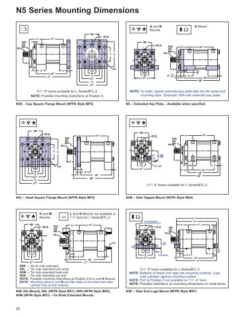
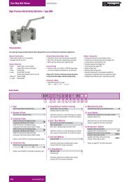
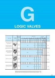
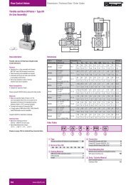
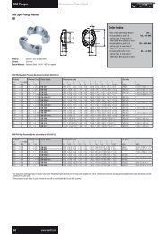
N5 Series Mounting DimensionsKK❍RODDIA.MMY•KP• ★RMEE (2)12 4RTF✠ ✾ ♠ A and BMounts ❚ Ω E MountRM1EE (2)RODDIA.MMKKY•P• ★ACVFGLB ★ZF ★JFH3DFLATSBRE SQTFUF SQFB‡423DFLATSBE SQA-.013FH -.015CWVBGFH2ZB ★ LB★JK3 1 /4"- 8" bores available for L Series/BTL-2.NOTE: Possible mounting restrictions at Position 5.N5S – Cap Square Flange Mount (NFPA Style MF6)NOTE: To order, specify extended key plate after the N5 series andmounting style. (Example: N5A with extended key plate)N5 – Extended Key Plate – Available when specified✠ ✾ ♠✠ ✾ ♠RM1EE (2)RODDIA.MMKKY•P• ★RMB1EE (2)RODDIA.MM KKY•P• ★423DFLATSBRE SQTFUF SQRTFFB‡ACVBFHWGLB ★ZB ★JK43DFLATSTNE SQ2TKE -.0052 -.010NT TAPACVFXTGSN ★LB ★ZB ★2 1 /2"- 8" bores available for L Series/BTL-2.JKN5J – Head Square Flange Mount (NFPA Style MF5)N5B – Side Tapped Mount (NFPA Style MS4)4✠ ✾ ♠RM13DFLATSBRE SQK and MMountsEE (2)2AARODDIA.MMKK∞ABBL and N Mounts not available in1 1 /2" bore for L Series/BTL-2Y•CVBFHWGP• ★LB ★ZT ★N5K – No tie rods extendedN5L – Tie rods extended both endsN5M – Tie rods extended head endN5N – Tie rods extended cap endNOTE: Possible mounting restrictions at Position 5 for L and N Mounts.NOTE: Mounting styles L and M use filler plate at the head end whencylinder has circular retainer.N5K (No Mount), N5L (NFPA Style MX1), N5N (NFPA Style MX2),N5M (NFPA Style MX3) – Tie Rods Extended MountsJKBBDD❚ ΩEG4DIA. COUNTERBOREEF 2 HOLES HEAD END ONLYRMEE (2)13DFLATSBBLE SQ2E -.0052 -.010ETRODDIA.MMKKEB‡1/64 APPROX.AY•CVBFHWN5E – Side End Lugs Mount (NFPA Style MS7)GZE ★ XE ★P• ★KEOJ ELLB ★SE ★3 1 /4"- 8" bores available for L Series/BTL-2.NOTE: Bottoms of heads and caps are mounting surfaces. Lugshold cylinders against mounting surface.NOTE: Port at Position 3 not available on 1 1 /2" -4" bore.NOTE: Possible restrictions on mounting dimensions on small bores.24
Cylinder DimensionsBORE 1 1 /2 2 2 1 /2 3 1 /4 4 5 6 7 8A 1 1 /8 1 1 /8 1 1 /8 1 5 /8 2 2 1 /4 3 3 1 /2 3 1 /2AA 2.3 2.9 3.6 4.6 5.4 7.0 8.1 9.3 10.6B -.001-.003BB1 1 /21 3 /81 1 /21 13 /161 1 /21 13 /1622 5 /162 3 /82 5 /162 5 /83 3 /163 1 /83 5 /83 3 /44 1 /84 1 /44 1 /2C 1/2 1/2 1/2 5/8 3/4 7/8 1 1 1CC 1/2-20 7 /8-14 7 /8-14 1 1 /4-12 1 1 /2-12 1 3 /4-12 2 1 /4-12 2 3 /4-12 3 1 /4-12D 7/8 7/8 7/8 1 1 /8 1 1 /2 1 3 /4 2 1 /8 2 5 /8 3DD 3/8-24 1 /2-20 1 /2-20 5 /8-18 5 /8-18 7 /8-14 1-14 1 1 /8-12 1 1 /4-12E 2 1 /2 3 3 1 /2 4 1 /2 5 6 1 /2 7 1 /2 8 1 /2 9 1 /2EE (SAE) 10 10 10 12 12 12 16 20 24EE (NPTF) 1/2 1/2 1/2 3/4 3/4 3/4 1 1 1 /4 1 1 /2EF 5 /813 /1613 /16 1 1 1 3 /8 1 5 /8 1 5 /8 2 3 /32EG 11 /163 /43 /4 1 1 /167 /8 1 1 /4 1 1 /2 1 1 /2 1 3 /4EL 7 /815 /1615 /16 1 1 /8 1 1 /8 1 1 /2 1 11 /16 1 13 /16 2EO 3 /81 /21 /25 /85 /83 /47 /8 1 1 1 /8ET 7 /8 1 1 1 1 /4 1 1 /4 1 1 /2 1 3 /4 2 2F ▲ ▲ 1/2 19/32 19/32 19/32 19/32 23/32 23/32FB‡ 7/16 9/16 9/16 11/16 11/16 15/16 1 1 /16 1 3 /16 1 5 /16FH 3/8 5/8 5/8 3/4 7/8 7/8 1 1 1FT 5/8-18 1-14 1-14 1 3 /8-12 1 3 /4-12 2-12 2 1 /2-12 3-12 3 1 /2-12G 1 3 /4 1 3 /4 1 3 /4 2 2 2 2 1 /4 2 3 /4 3K 3/8 7/16 7/16 9/16 9/16 13/16 15/16 1 1 1 /8KK 3/4-16 3 /4-16 3 /4-16 1-14 1 1 /4-12 1 1 /2-12 1 7 /8-12 2 1 /4-12 2 1 /2-12MM 1 1 1 1 3 /8 1 3 /4 2 2 1 /2 3 3 1 /2NT 3/8-16 1 /2-13 5 /8-11 3 /4-10 1-8 1-8 1 1 /4-7 1 1 /2-6 1 1 /2-6R 1.63 2.05 2.55 3.25 3.82 4.95 5.73 6.58 7.50RM ■ ■ 2 5 /8 3 1 /4 3 7 /8 4 4 7 /16 5 1 /4 5 5 /8TF 3 7 /16 4 1 /8 4 5 /8 5 7 /8 6 3 /8 8 3 /16 9 7 /16 10 5 /8 11 13 /16TK 9/16 1/2 13/16 3/4 1 1 1 /8 1 5 /16 2 1 /8 1 9 /16TN 3/4 15/16 1 5 /16 1 1 /2 2 1 /16 2 15 /16 3 5 /16 3 3 /4 4 1 /4UF 4 1 /4 5 1 /8 5 5 /8 7 1 /8 7 5 /8 9 3 /4 11 1 /4 12 5 /8 14V ▲ ▲ 3/8 13/32 17/32 17/32 21/32 17/32 17/32VB 1/2 1/4 1/4 1/4 1/4 1/4 1/4 1/4 1/4W 1 3/4 3/4 7/8 1 1 1 /8 1 1 /4 1 1 /4 1 1 /4XT 2 2 3 /8 2 3 /8 2 3 /4 3 3 1 /8 3 1 /2 3 13 /16 3 15 /16Y• 2 15 /32 2 15 /32 2 15 /32 2 23 /32 2 31 /32 3 3 /32 3 19 /32 3 15 /16 4 1 /16LB + StrokeJJJ<strong>Electronic</strong> <strong>Feedback</strong> CylinderDimensional ChangesBORE 1 1 /2 2 2 1 /2 3 1 /4 4 5 6 8C HLT II – 7/8 7/8 3/4 9/16 3/16 ¬ ¬** L Series/BTL-2 ¬ ¬ ¬ ¬ ¬ ¬ ¬ ¬RT ¬ ¬ ¬ ¬ ¬ ¬ ¬ ¬**Style 4 rod ends may require additional rod length. The following dimensions willincrease by the C dimension in the above chart: C, SE, W, WF, XC, XD, XE, XG,XJ, XS, XT, Y, ZB, ZE, ZF, ZJ and ZT.J HLT II – 2 1 /4 2 1 /8 2 2 2 2 1 /4 2 3 /4 3L Series/BTL-2 1 1 /2 1 1 /2 1 1 /2 1 3 /4 1 3 /4 1 3 /4 2 1 /4 2 3 /4 3RT 1 1 /2 1 1 /2 1 1 /2 1 3 /4 1 3 /4 1 3 /4 2 1 /4 2 3 /4 3JJ◆ HLT II – 3/8 3/8 3/8 3/8 3/8 3/8 3/8 3/8LB★ HLT II – 5 3 /8 5 3 /8 5 3 /4 6 6 1 /2 7 3 /8 8 1 /2 9 1 /2L Series/BTL-2 5 1 /2 5 1 /2 5 5 /8 5 1 /2 5 3 /4 6 1 /4 7 3 /8 8 1 /2 9 1 /2RT 5 5 /8 5 5 /8 5 3 /4 5 1 /2 5 3 /4 6 1 /4 7 3 /8 8 1 /2 9 1 /2P•★ HLT II – 2 11 /16 2 13 /16 3 9 /16 3 13 /16 4 5 /16 4 11 /16 5 1 /8 5 7 /8L Series/BTL-2 3 9 /16 3 9 /16 3 11 /16 3 9 /16 3 13 /16 4 5 /16 4 11 /16 5 1 /8 5 7 /8RT 3 11 /16 3 11 /16 3 13 /16 3 9 /16 3 13 /16 4 5 /16 4 11 /16 5 1 /8 5 7 /8SE★ HLT II – 8 1 /4 7 7 /8 8 3 /4 9 1 /8 10 3 /8 11 3 /4 13 1 /8 14 1 /2L Series/BTL-2 7 5 /8 8 8 8 1 /2 8 7 /8 10 1 /8 11 3 /4 13 1 /8 14 1 /2RT 7 3 /4 8 1 /8 8 1 /4 8 1 /2 8 7 /8 10 1 /8 11 3 /4 13 1 /8 14 1 /2SN★ HLT II – 2 7 /8 3 3 1 /2 3 3 /4 4 1 /4 5 1 /8 5 7 /8 6 5 /8L Series/BTL-2 3 3 /4 3 3 /4 3 7 /8 3 1 /2 3 3 /4 4 1 /4 5 1 /8 5 7 /8 6 5 /8RT 3 7 /8 3 7 /8 4 3 1 /2 3 3 /4 4 1 /4 5 1 /8 5 7 /8 6 5 /8XE★ HLT II – 8 1 /16 7 11 /16 8 1 /2 9 10 11 5 /16 12 9 /16 13 3 /4L Series/BTL-2 N/A 7 13 /16 7 15 /16 8 1 /4 8 3 /4 9 3 /4 11 5 /16 12 9 /16 13 3 /4RT 7 7 /8 7 15 /16 8 1 /16 8 1 /4 8 3 /4 9 3 /4 11 5 /16 12 9 /16 13 3 /4ZB★ HLT II – 7 9 /16 7 3 /16 7 15 /16 8 7 /16 9 5 /16 10 9 /16 11 3 /4 12 7 /8L Series/BTL-2 7 1 /4 7 5 /16 7 7 /16 7 11 /16 8 3 /16 9 1 /16 10 9 /16 11 3 /4 12 7 /8RT 7 3 /8 7 7 /16 7 9 /16 7 11 /16 8 3 /16 9 1 /16 10 9 /16 11 3 /4 12 7 /8ZE★ HLT II – 8 9 /16 8 3 /16 9 1 /8 9 5 /8 10 3 /4 12 3 /16 13 9 /16 14 7 /8L Series/BTL-2 N/A 8 5 /16 8 7 /16 8 7 /8 9 3 /8 10 1 /2 12 3 /16 13 9 /16 14 7 /8RT 8 1 /4 8 7 /16 8 9 /16 8 7 /8 9 3 /8 10 1 /2 12 3 /16 13 9 /16 14 7 /8ZF★ HLT II – 7 3 /8 7 3 /8 8 1 /8 8 3 /4 9 3 /8 10 5 /8 11 3 /4 12 3 /4L Series/BTL-2 7 1 /4 7 1 /2 7 5 /8 7 7 /8 8 1 /2 9 1 /8 10 5 /8 11 3 /4 12 3 /4RT 7 3 /8 7 5 /8 7 3 /4 7 7 /8 8 1 /2 9 1 /8 10 5 /8 11 3 /4 12 3 /4ZT★ HLT II – 8 15 /16 8 9 /16 9 11 /16 10 3 /16 11 11 /16 13 1 /4 14 7 /8 16 1 /4L Series/BTL-2 8 1 /4 8 11 /16 8 13 /16 9 7 /16 9 15 /16 11 7 /16 13 1 /4 14 7 /8 16 1 /4RT 8 3 /8 8 13 /16 8 15 /16 9 7 /16 9 15 /16 11 7 /16 13 1 /4 14 7 /8 16 1 /4Dimensions shown in purple are mounting dimensions.NOTE: To determine piston thickness, subtract G and J dimensions from LBdimension.NOTE: Additional port information on page 20.Oversize rods affect dimensions in gray-shaded areas.See pages 30-31 for these dimensions.★ Add stroke to all starred dimensions.■ Requires full front square retainer.NOTE: Overall length dimensions that require addition of stroke may vary fromdimensions shown, due to manufacturing tolerances.▲ Use FH dimension in place of F dimension and VB dimension in place of Vdimension.◆ The JJ dimension is the cover plate thickness for the HLT II electonics. A squarecover plate is required on the 2" bore size while all others receive a circular type.‡ Use screws 1 ⁄16" smaller than mounting holes.• Port dimensions for standard ports only. Consult Hydro-Line for flange, manifoldand special ports.¬ No additional C required for a Style 4 rod end.CCLB + StrokeRefer to ordering code on pages 9, 11, 13 and 15:✠ Sensor cover not available for 1 1 ⁄2" bore.✾ A, B & C sensor cover options available for 2" bore.❖ A, B & C sensor cover options available for 2" and 2 1 ⁄2" bore.❚ A, B & C sensor cover options available for 2"-3 1 ⁄4" bore.∞ A, B & C sensor cover options available for 2"-8" bore.✧ B & C sensor cover options available for 2"-8" bore.♠ All sensor cover options available for 2 1 ⁄2"-8" bores.❍ All sensor cover options available for 3 1 ⁄4"-8" bores.Ω All sensor cover options available for 4"-8" bores.NOTE: Consult factory on applications requiring cushionsor bores over 8".NOTE: Consult factory on applications requiring 1 1 ⁄2" bore HLT II.25