Electronic Feedback Cylinders - Lifco Hydraulics USA
Electronic Feedback Cylinders - Lifco Hydraulics USA
Electronic Feedback Cylinders - Lifco Hydraulics USA

You also want an ePaper? Increase the reach of your titles
YUMPU automatically turns print PDFs into web optimized ePapers that Google loves.
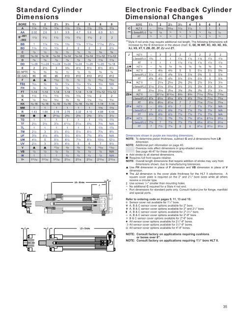
Standard CylinderDimensionsBORE 1 1 /2 2 2 1 /2 3 1 /4 4 5 6 8A 1 1 /8 1 1 /8 1 1 /8 1 1 /8 1 1 /8 1 1 /8 1 5 /8 1 5 /8AA 2.02 2.6 3.1 3.9 4.7 5.8 6.9 9.1B -.001-.0031 1 /2 1 1 /2 1 1 /2 1 1 /2 1 1 /2 1 1 /2 2 2BB 1 1 1 /8 1 1 /8 1 3 /8 1 3 /8 1 13 /16 1 13 /16 2 5 /16BD 1 1 /4 1 1 /2 1 1 /2 2 2 2 2 2 1 /2C 1/2 1/2 1/2 1/2 1/2 1/2 5/8 5/8CC 7/8-14 7/8-14 7/8-14 7/8-14 7/8-14 7/8-14 1 1 /4-12 1 1 /4-12D 7/8 7/8 7/8 7/8 7/8 7/8 1 1 /8 1 1 /8DD 1/4-28 5/16-24 5/16-24 3/8-24 3/8-24 1/2-20 1/2-20 5/8-18E 2 2 1 /2 3 3 3 /4 4 1 /2 5 1 /2 6 1 /2 8 1 /2EE (NPTF) 3/8 3/8 3/8 1/2 1/2 1/2 3/4 3/4EE (SAE) #6 #6 #6 #10 #10 #10 #12 #12F ▲ ▲ 11/32 1/2 1/2 1/2 19/32 19/32FB‡ 5/16 3/8 3/8 7/16 7/16 9/16 9/16 N/AFH 3/8 3/8 3/8 5/8 5/8 5/8 3/4 3/4FT 1-14 1-14 1-14 1-14 1-14 1-14 1 3 /8-12 1 3 /8-12G 1 1 /2 1 1 /2 1 1 /2 1 3 /4 1 3 /4 1 3 /4 2 2K 1/4 5/16 5/16 3/8 3/8 7/16 7/16 9/16KK 3/4-16 3/4-16 3/4-16 3/4-16 3/4-16 3/4-16 1-14 1-14MM 1 1 1 1 1 1 1 3 /8 1 3 /8R 1.43 1.84 2.19 2.76 3.32 4.10 4.88 6.44RM ■ ■ 2 31 /64 2 5 /8 2 5 /8 2 5 /8 3 1 /4 3 1 /4TD 1 1 1 1 1 1 1 3 /8 1 3 /8TF 2 3 /4 3 3 /8 3 7 /8 4 11 /16 5 7 /16 6 5 /8 7 5 /8 N/ATL 1 1 1 1 1 1 1 3 /8 1 3 /8TM 2 1 /2 3 3 1 /2 4 1 /2 5 1 /4 6 1 /4 7 5 /8 9 3 /4UF 3 3 /8 4 1 /8 4 5 /8 5 1 /2 6 1 /4 7 5 /8 8 5 /8 N/AUM 4 1 /2 5 5 1 /2 6 1 /2 7 1 /4 8 1 /4 10 3 /8 12 1 /2UV 2 1 /2 3 3 1 /2 4 1 /4 5 6 7 9 1 /2V ▲ ▲ 17/32 3/8 3/8 3/8 13/32 13/32VB 1/2 1/2 1/2 1/4 1/4 1/4 1/4 N/AW 1 1 1 3/4 3/4 3/4 7/8 N/AY• 1 31 /32 1 31 /32 1 31 /32 2 7 /16 2 7 /16 2 7 /16 2 13 /16 2 13 /16LB + StrokeJJJ<strong>Electronic</strong> <strong>Feedback</strong> CylinderDimensional ChangesBORE 1 1 /2 2 2 1 /2 3 1 /4 4 5 6 8C HLT II – 1 9 /16 1 9 /16 1 1 /4 1 1 /4 1 1 1** L Series/BTL-2 1/8 1/8 ¬ ¬ ¬ ¬ 3/8 1/4RT ¬ ¬ ¬ ¬ ¬ ¬ ¬ ¬**Style 4 rod ends may require additional rod length. The following dimensions willincrease by the C dimension in the above chart: C, SE, W, WF, XC, XD, XE, XG,XJ, XS, XT, Y, ZB, ZE, ZF, ZJ and ZT.J HLT II – 2 2 2 2 2 2 2L Series/BTL-2 1 3 /4 1 1 1 1 /4 1 1 /4 1 1 /4 1 1 /2 1 1 /2RT 1 1 1 1 1 /4 1 1 /4 1 1 /4 1 1 /2 1 1 /2JJ◆ HLT II – 3/8 3/8 3/8 3/8 3/8 3/8 3/8LB★ HLT II – 4 5 /8 4 3 /4 5 5 5 1 /4 5 1 /2 5 5 /8L Series/BTL-2 5 1 /4 4 1 /2 4 5 /8 5 1 /8 5 1 /8 5 3 /8 5 5 1 /8RT 4 5 /8 4 5 /8 4 3 /4 5 1 /4 5 1 /4 5 1 /4 5 5 1 /8P•★ HLT II – 2 3 /16 2 5 /16 2 5 /8 2 5 /8 2 7 /8 3 1 /8 3 1 /4L Series/BTL-2 3 1 /16 3 1 /16 3 3 /16 3 1 /2 3 1 /2 3 3 /4 3 1 /8 3 1 /4RT 3 3 /16 3 3 /16 3 5 /16 3 5 /8 3 5 /8 3 5 /8 3 1 /8 3 1 /4ZB★ HLT II – 6 11 /16 6 13 /16 6 3 /4 6 3 /4 7 1 /16 7 9 /16 7 13 /16L Series/BTL-2 6 7 /8 6 3 /16 6 5 /16 6 7 /8 6 7 /8 7 3 /16 7 1 /16 7 5 /16RT 6 1 /4 6 5 /16 6 7 /16 7 7 7 1 /16 7 1 /16 7 5 /16ZF★ HLT II – 6 3 /8 6 1 /2 7 7 7 1 /4 7 7 /8 N/AL Series/BTL-2 7 6 1 /4 6 3 /8 7 1 /8 7 1 /8 7 3 /8 7 3 /8 N/ART 6 3 /8 6 3 /8 6 1 /2 7 1 /4 7 1 /4 7 1 /4 7 3 /8 N/AZT★ HLT II – 7 1 /2 7 5 /8 7 3 /4 7 3 /4 8 7 /16 8 15 /16 9 9 /16L Series/BTL-2 7 5 /8 7 7 1 /8 7 7 /8 7 7 /8 8 9 /16 8 7 /16 9 1 /16RT 7 7 1 /8 7 1 /4 8 8 8 7 /16 8 7 /16 9 1 /16Dimensions shown in purple are mounting dimensions.NOTE: To determine piston thickness, subtract G and J dimensions from LBdimension.NOTE: Additional port information on page 40.Oversize rods affect dimensions in gray-shaded areas.See page 46-47 for these dimensions.★ Add stroke to all starred dimensions.■ Requires full front square retainer.NOTE: Overall length dimensions that require addition of stroke may vary fromdimensions shown, due to manufacturing tolerances.▲ Use FH dimension in place of F dimension and VB dimension in place of Vdimension.◆ The JJ dimension is the cover plate thickness for the HLT II electronics. Asquare cover plate is required on the 2" and 2 1 /2" bore sizes while all othersreceive a circular type.‡ Use screws 1 /16" smaller than mounting holes.¬ No additional C required for a Style 4 rod end.• Port dimensions for standard ports only. Consult Hydro-Line for flange, manifoldand special ports.CCLB + StrokeRefer to ordering code on pages 9, 11, 13 and 15:✠ Sensor cover not available for 1 1 /2" bore.✾ A, B & C sensor cover options available for 2" bore.❖ A, B & C sensor cover options available for 2" and 2 1 /2" bore.❚ A, B & C sensor cover options available for 2"-3 1 /4" bore.∞ A, B & C sensor cover options available for 2"-8" bore.✧ B & C sensor cover options available for 2"-8" bore.♠ All sensor cover options available for 2 1 /2"-8" bores.❍ All sensor cover options available for 3 1 /4"-8" bores.Ω All sensor cover options available for 4"-8" bores.NOTE: Consult factory on applications requiring cushionsor bores over 8".NOTE: Consult factory on applications requiring 1 1 ⁄2" bore HLT II.35