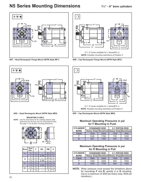
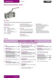
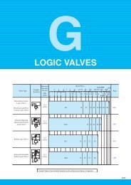
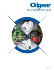
N5 Series Mounting Dimensions1 1 /2" - 8" bore cylinders✠ ✾ ♠❍RM1EE (2)KKRODDIA.MMY•P• ★RODDIA.MMKKY•KP• ★RM1EE (2)42RR2 43DFLATSBE SQTFUFFB‡AC VBFHWG J KLB ★ZB ★ACVFG J FHLB ★ZF ★FB‡3DFLATSBE SQTFUF3 1 /4"- 8" bores available for L Series/BTL-2.NOTE: Possible mounting restrictions at Position 5.N5F – Head Rectangular Flange Mount (NFPA Style MF1)N5R – Cap Rectangular Flange Mount (NFPA Style MF2)✠ ✾ ♠❍RMEE (2)1 RODDIA.MMKKY•P• ★RODDIA.MMKKY•KP• ★RM1EE (2)42R2 4R3DFLATSBE SQTFUFFB‡ACVFWFG J KLB ★ZB ★ACVFGLB ★ZJ ★J3DFLATSBESQTFUF.3 1 /4"- 8" bores available for L Series/BTL-2.NOTE: Possible mounting restrictions at Position 5.FB‡22N5G – Head Rectangular Mount (NFPA Style ME5)MOUNTING G ONLYNOTE: Use the chart below for the cartridge retainer platedimensions for the bore and rod combinations listed.See page 11 for all other mounting dimensions.4Bore1 1 /222 1 /23 1 /413RMDIA.RodDia.5/82RARef.C11/32 – 2 3 /81 1/2 2.44 2 5 /81 1/2 – 2 5 /819/32 2.94 3 1 /41 3 /81 3 /81 3 /41 3 /4F RA RM V19/32 – 3 1 /419/32 3.44 3 7 /819/32 – 3 7 /8FV9/323/83/813/3213/3217/3217/32219/32 – 417/32N5P – Cap Rectangular Mount (NFPA Style ME6)Maximum Operating Pressures in psifor F Mounting in PushCYLINDER STANDARD ROD 2:1 PISTON RODBORE Heavy Duty Nonshock Heavy Duty Nonshock5 & 6 1440 2400 1120 18407 1040 1760 720 12008 800 1350 640 1120Maximum Operating Pressures in psifor R Mounting in PullCYLINDER STANDARD ROD 2:1 PISTON RODBORE Heavy Duty Nonshock Heavy Duty Nonshock5 & 6 1800 3000 1400 23007 1300 2200 900 15008 1000 1700 800 1400NOTE: When pressure must exceed the limitations abovefor mountings F and R, specify J or S mounting.(Up to a maximum of 3000 psi heavy duty, 5000 psinonshock.)
Cylinder DimensionsBORE 1 1 /2 2 2 1 /2 3 1 /4 4 5 6 7 8A 1 1 /8 1 1 /8 1 1 /8 1 5 /8 2 2 1 /4 3 3 1 /2 3 1 /2AA 2.3 2.9 3.6 4.6 5.4 7.0 8.1 9.3 10.6B -.001-.003C1 1 /21/21 1 /21/21 1 /21/225/82 3 /83/42 5 /87/83 1 /813 3 /414 1 /41CC 1/2-20 7 /8-14 7 /8-14 1 1 /4-12 1 1 /2-12 1 3 /4-12 2 1 /4-12 2 3 /4-12 3 1 /4-12D 7/8 7/8 7/8 1 1 /8 1 1 /2 1 3 /4 2 1 /8 2 5 /8 3E 2 1 /2 3 3 1 /2 4 1 /2 5 6 1 /2 7 1 /2 8 1 /2 9 1 /2EE (SAE) 10 10 10 12 12 12 16 20 24EE (NPTF) 1/2 1/2 1/2 3/4 3/4 3/4 1 1 1 /4 1 1 /2F ▲ ▲ 1/2 19/32 19/32 19/32 19/32 23/32 23/32FB‡ 7/16 9/16 9/16 11/16 11/16 15/16 1 1 /16 1 3 /16 1 5 /16FH 3/8 5/8 5/8 3/4 7/8 7/8 1 1 1FT 5/8-18 1-14 1-14 1 3 /8-12 1 3 /4-12 2-12 2 1 /2-12 3-12 3 1 /2-12G 1 3 /4 1 3 /4 1 3 /4 2 2 2 2 1 /4 2 3 /4 3K 3/8 7/16 7/16 9/16 9/16 13/16 15/16 1 1 1 /8KK 3/4-16 3 /4-16 3 /4-16 1-14 1 1 /4-12 1 1 /2-12 1 7 /8-12 2 1 /4-12 2 1 /2-12MM 1 1 1 1 3 /8 1 3 /4 2 2 1 /2 3 3 1 /2R 1.63 2.05 2.55 3.25 3.82 4.95 5.73 6.58 7.50RM ■ ■ 2 5 /8 3 1 /4 3 7 /8 4 4 7 /16 5 1 /4 5 5 /8TF 3 7 /16 4 1 /8 4 5 /8 5 7 /8 6 3 /8 8 3 /16 9 7 /16 10 5 /8 11 13 /16UF 4 1 /4 5 1 /8 5 5 /8 7 1 /8 7 5 /8 9 3 /4 11 1 /4 12 5 /8 14V ▲ ▲ 3/8 13/32 17/32 17/32 21/32 17/32 17/32VB 1/2 1/4 1/4 1/4 1/4 1/4 1/4 1/4 1/4W 1 3/4 3/4 7/8 1 1 1 /8 1 1 /4 1 1 /4 1 1 /4WF 1 3 /8 1 3 /8 1 3 /8 1 5 /8 1 7 /8 2 2 1 /4 2 1 /4 2 1 /4Y• 2 15 /32 2 15 /32 2 15 /32 2 23 /32 2 31 /32 3 3 /32 3 19 /32 3 15 /16 4 1 /16LB + StrokeJJJ<strong>Electronic</strong> <strong>Feedback</strong> CylinderDimensional ChangesBORE 1 1 /2 2 2 1 /2 3 1 /4 4 5 6 8C HLT II – 7/8 7/8 3/4 9/16 3/16 ¬ ¬** L Series/BTL-2 ¬ ¬ ¬ ¬ ¬ ¬ ¬ ¬RT ¬ ¬ ¬ ¬ ¬ ¬ ¬ ¬**Style 4 rod ends may require additional rod length. The following dimensions willincrease by the C dimension in the above chart: C, SE, W, WF, XC, XD, XE, XG,XJ, XS, XT, Y, ZB, ZE, ZF, ZJ and ZT.J HLT II – 2 1 /4 2 1 /8 2 2 2 2 1 /4 2 3 /4 3L Series/BTL-2 1 1 /2 1 1 /2 1 1 /2 1 3 /4 1 3 /4 1 3 /4 2 1 /4 2 3 /4 3RT 1 1 /2 1 1 /2 1 1 /2 1 3 /4 1 3 /4 1 3 /4 2 1 /4 2 3 /4 3JJ◆ HLT II – 3/8 3/8 3/8 3/8 3/8 3/8 3/8 3/8LB★ HLT II – 5 3 /8 5 3 /8 5 3 /4 6 6 1 /2 7 3 /8 8 1 /2 9 1 /2L Series/BTL-2 5 1 /2 5 1 /2 5 5 /8 5 1 /2 5 3 /4 6 1 /4 7 3 /8 8 1 /2 9 1 /2RT 5 5 /8 5 5 /8 5 3 /4 5 1 /2 5 3 /4 6 1 /4 7 3 /8 8 1 /2 9 1 /2P•★ HLT II – 2 11 /16 2 13 /16 3 9 /16 3 13 /16 4 5 /16 4 11 /16 5 1 /8 5 7 /8L Series/BTL-2 3 9 /16 3 9 /16 3 11 /16 3 9 /16 3 13 /16 4 5 /16 4 11 /16 5 1 /8 5 7 /8RT 3 11 /16 3 11 /16 3 13 /16 3 9 /16 3 13 /16 4 5 /16 4 11 /16 5 1 /8 5 7 /8ZB★ HLT II – 7 9 /16 7 3 /16 7 15 /16 8 7 /16 9 5 /16 10 9 /16 11 3 /4 12 7 /8L Series/BTL-2 7 1 /4 7 5 /16 7 7 /16 7 11 /16 8 3 /16 9 1 /16 10 9 /16 11 3 /4 12 7 /8RT 7 3 /8 7 7 /16 7 9 /16 7 11 /16 8 3 /16 9 1 /16 10 9 /16 11 3 /4 12 7 /8ZF★ HLT II – 7 3 /8 7 3 /8 8 1 /8 8 3 /4 9 3 /8 10 5 /8 11 3 /4 12 3 /4L Series/BTL-2 7 1 /4 7 1 /2 7 5 /8 7 7 /8 8 1 /2 9 1 /8 10 5 /8 11 3 /4 12 3 /4RT 7 3 /8 7 5 /8 7 3 /4 7 7 /8 8 1 /2 9 1 /8 10 5 /8 11 3 /4 12 3 /4ZJ★ HLT II – 6 3 /4 6 3 /4 7 3 /8 7 7 /8 8 1 /2 9 5 /8 10 3 /4 11 3 /4L Series/BTL-2 6 7 /8 6 7 /8 7 7 1 /8 7 5 /8 8 1 /4 9 5 /8 10 3 /4 11 3 /4RT 7 7 7 1 /8 7 1 /8 7 5 /8 8 1 /4 9 5 /8 10 3 /4 11 3 /4Dimensions shown in purple are mounting dimensions.NOTE: To determine piston thickness, subtract G and J dimensions from LBdimension.NOTE: Additional port information on page 20.Oversize rods affect dimensions in gray-shaded areas.See pages 30-31for these dimensions.★ Add stroke to all starred dimensions.■ Requires full front square retainer.NOTE: Overall length dimensions that require addition of stroke may vary fromdimensions shown, due to manufacturing tolerances.▲ Use FH dimension in place of F dimension and VB dimension in place of Vdimension.◆ The JJ dimension is the cover plate thicknessfor the HLT II electonics. A squarecover plate is required on the 2" bore size while all others receive a circular type.‡ Use screws 1 ⁄16" smaller than mounting holes.• Port dimensions for standard ports only. Consult Hydro-Line for flange, manifoldand special ports.¬ No additional C required for a Style 4 rod end.CCLB + StrokeRefer to ordering code on pages 9, 11, 13 and 15:✠ Sensor cover not available for 1 1 ⁄2" bore.✾ A, B & C sensor cover options available for 2" bore.❖ A, B & C sensor cover options available for 2" and 2 1 ⁄2" bore.❚ A, B & C sensor cover options available for 2"-3 1 ⁄4" bore.∞ A, B & C sensor cover options available for 2"-8" bore.✧ B & C sensor cover options available for 2"-8" bore.♠ All sensor cover options available for 2 1 ⁄2"-8" bores.❍ All sensor cover options available for 3 1 ⁄4"-8" bores.Ω All sensor cover options available for 4"-8" bores.NOTE: Consult factory on applications requiring cushionsor bores over 8".NOTE: Consult factory on applications requiring 1 1 ⁄2" bore HLT II.23